JP7079046B2 - Air conditioning ventilation system - Google Patents
Air conditioning ventilation system Download PDFInfo
- Publication number
- JP7079046B2 JP7079046B2 JP2021564000A JP2021564000A JP7079046B2 JP 7079046 B2 JP7079046 B2 JP 7079046B2 JP 2021564000 A JP2021564000 A JP 2021564000A JP 2021564000 A JP2021564000 A JP 2021564000A JP 7079046 B2 JP7079046 B2 JP 7079046B2
- Authority
- JP
- Japan
- Prior art keywords
- air
- ventilation
- unit
- heat exchange
- conditioning
- Prior art date
- Legal status (The legal status is an assumption and is not a legal conclusion. Google has not performed a legal analysis and makes no representation as to the accuracy of the status listed.)
- Active
Links
Images


Classifications
-
- F—MECHANICAL ENGINEERING; LIGHTING; HEATING; WEAPONS; BLASTING
- F24—HEATING; RANGES; VENTILATING
- F24F—AIR-CONDITIONING; AIR-HUMIDIFICATION; VENTILATION; USE OF AIR CURRENTS FOR SCREENING
- F24F7/00—Ventilation
- F24F7/04—Ventilation with ducting systems, e.g. by double walls; with natural circulation
- F24F7/06—Ventilation with ducting systems, e.g. by double walls; with natural circulation with forced air circulation, e.g. by fan positioning of a ventilator in or against a conduit
- F24F7/08—Ventilation with ducting systems, e.g. by double walls; with natural circulation with forced air circulation, e.g. by fan positioning of a ventilator in or against a conduit with separate ducts for supplied and exhausted air with provisions for reversal of the input and output systems
-
- F—MECHANICAL ENGINEERING; LIGHTING; HEATING; WEAPONS; BLASTING
- F24—HEATING; RANGES; VENTILATING
- F24F—AIR-CONDITIONING; AIR-HUMIDIFICATION; VENTILATION; USE OF AIR CURRENTS FOR SCREENING
- F24F11/00—Control or safety arrangements
- F24F11/62—Control or safety arrangements characterised by the type of control or by internal processing, e.g. using fuzzy logic, adaptive control or estimation of values
- F24F11/63—Electronic processing
- F24F11/65—Electronic processing for selecting an operating mode
-
- F—MECHANICAL ENGINEERING; LIGHTING; HEATING; WEAPONS; BLASTING
- F24—HEATING; RANGES; VENTILATING
- F24F—AIR-CONDITIONING; AIR-HUMIDIFICATION; VENTILATION; USE OF AIR CURRENTS FOR SCREENING
- F24F12/00—Use of energy recovery systems in air conditioning, ventilation or screening
- F24F12/001—Use of energy recovery systems in air conditioning, ventilation or screening with heat-exchange between supplied and exhausted air
-
- F—MECHANICAL ENGINEERING; LIGHTING; HEATING; WEAPONS; BLASTING
- F24—HEATING; RANGES; VENTILATING
- F24F—AIR-CONDITIONING; AIR-HUMIDIFICATION; VENTILATION; USE OF AIR CURRENTS FOR SCREENING
- F24F13/00—Details common to, or for air-conditioning, air-humidification, ventilation or use of air currents for screening
- F24F13/22—Means for preventing condensation or evacuating condensate
- F24F13/222—Means for preventing condensation or evacuating condensate for evacuating condensate
-
- F—MECHANICAL ENGINEERING; LIGHTING; HEATING; WEAPONS; BLASTING
- F24—HEATING; RANGES; VENTILATING
- F24F—AIR-CONDITIONING; AIR-HUMIDIFICATION; VENTILATION; USE OF AIR CURRENTS FOR SCREENING
- F24F3/00—Air-conditioning systems in which conditioned primary air is supplied from one or more central stations to distributing units in the rooms or spaces where it may receive secondary treatment; Apparatus specially designed for such systems
- F24F3/044—Systems in which all treatment is given in the central station, i.e. all-air systems
-
- F—MECHANICAL ENGINEERING; LIGHTING; HEATING; WEAPONS; BLASTING
- F24—HEATING; RANGES; VENTILATING
- F24F—AIR-CONDITIONING; AIR-HUMIDIFICATION; VENTILATION; USE OF AIR CURRENTS FOR SCREENING
- F24F7/00—Ventilation
- F24F7/007—Ventilation with forced flow
-
- F—MECHANICAL ENGINEERING; LIGHTING; HEATING; WEAPONS; BLASTING
- F24—HEATING; RANGES; VENTILATING
- F24F—AIR-CONDITIONING; AIR-HUMIDIFICATION; VENTILATION; USE OF AIR CURRENTS FOR SCREENING
- F24F2110/00—Control inputs relating to air properties
- F24F2110/10—Temperature
- F24F2110/12—Temperature of the outside air
-
- F—MECHANICAL ENGINEERING; LIGHTING; HEATING; WEAPONS; BLASTING
- F24—HEATING; RANGES; VENTILATING
- F24F—AIR-CONDITIONING; AIR-HUMIDIFICATION; VENTILATION; USE OF AIR CURRENTS FOR SCREENING
- F24F2110/00—Control inputs relating to air properties
- F24F2110/20—Humidity
-
- Y—GENERAL TAGGING OF NEW TECHNOLOGICAL DEVELOPMENTS; GENERAL TAGGING OF CROSS-SECTIONAL TECHNOLOGIES SPANNING OVER SEVERAL SECTIONS OF THE IPC; TECHNICAL SUBJECTS COVERED BY FORMER USPC CROSS-REFERENCE ART COLLECTIONS [XRACs] AND DIGESTS
- Y02—TECHNOLOGIES OR APPLICATIONS FOR MITIGATION OR ADAPTATION AGAINST CLIMATE CHANGE
- Y02B—CLIMATE CHANGE MITIGATION TECHNOLOGIES RELATED TO BUILDINGS, e.g. HOUSING, HOUSE APPLIANCES OR RELATED END-USER APPLICATIONS
- Y02B30/00—Energy efficient heating, ventilation or air conditioning [HVAC]
- Y02B30/56—Heat recovery units
Description
本発明は、建物内の複数の部屋を空調部と送風部により空調し、熱交換ユニットで換気する空調換気システムに関する。 The present invention relates to an air-conditioning ventilation system in which a plurality of rooms in a building are air-conditioned by an air-conditioning unit and a ventilation unit, and ventilated by a heat exchange unit.
住宅は省エネで快適な暮らし実現のため、ますます高気密化、高断熱化が進んでいる。一方、空気がきれいで健康な暮らし実現のため、換気の重要性が増している。
従来、この種の空調換気システムは、建物内部に空調機室を設け、この空調機室に吸い込んだ空気をエアコンディショナーで温度調節し、複数の送風部により複数の部屋に送風して空調し、洗濯機・乾燥機・アイロンなどの設備をまとめて設置したユーティリティや床下からの換気空気を熱交換ユニットで外気と熱交換して排気するものが知られている(例えば、特許文献1参照)。
また、熱回収式換気システムとして、浴室からの換気空気が、浴室に設けられた浴室暖房乾燥機から分岐ボックスを通して、顕熱交換換気ユニットで外気と熱交換し、排気されるものが知られている(例えば、特許文献2参照)。
また、熱交換換気システムとして、浴室内の空気を通す浴室排気ダクトを全熱交換器の風下側の排気通路に接続するものが知られている(例えば、特許文献3参照)。
また、換気空調システムとして、熱交換気モードと普通換気モードと有する換気装置と空気調和装置を、室内温度、室内湿度、室外温度、及び室外湿度から室内エンタルピーと室外エンタルピーを演算することで、制御を行うものが知られている(例えば、特許文献4)。
さらに、空調換気システムとして、浴室・トイレからの換気空気を熱交換装置で外気と熱交換した後、空調装置の室外機の給気側に排出するものが知られている(例えば、特許文献5)。Houses are becoming more and more airtight and highly insulated in order to save energy and realize comfortable living. On the other hand, ventilation is becoming more important for the realization of a clean and healthy life.
Conventionally, in this type of air-conditioning ventilation system, an air-conditioning room is provided inside the building, the temperature of the air sucked into the air-conditioning room is controlled by an air-conditioning conditioner, and the air is blown to multiple rooms by multiple air-conditioning units to air-condition. There are known utilities in which equipment such as a washing machine, a dryer, and an iron are installed together, and a heat exchange unit that exchanges heat with the outside air and exhausts the ventilation air from under the floor (see, for example, Patent Document 1).
Further, as a heat recovery type ventilation system, it is known that the ventilation air from the bathroom is exhausted by exchanging heat with the outside air by the manifest heat exchange ventilation unit from the bathroom heater / dryer provided in the bathroom through the branch box. (See, for example, Patent Document 2).
Further, as a heat exchange ventilation system, a system in which a bathroom exhaust duct for passing air in a bathroom is connected to an exhaust passage on the leeward side of a total heat exchanger is known (see, for example, Patent Document 3).
Further, as a ventilation air conditioning system, a ventilation device and an air conditioner having a heat exchange air mode and a normal ventilation mode are controlled by calculating indoor enthalpy and outdoor enthalpy from indoor temperature, indoor humidity, outdoor temperature, and outdoor humidity. (For example, Patent Document 4).
Further, as an air-conditioning ventilation system, a system is known in which ventilation air from a bathroom / toilet is heat-exchanged with outside air by a heat exchange device and then discharged to the air supply side of an outdoor unit of the air-conditioning device (for example, Patent Document 5). ).
しかしながら、特許文献1に記載の空調換気システムでは、浴室からの換気空気の熱を回収するため、浴室からの換気空気を熱交換ユニットに入れると、冬季の入浴時には、高温度高湿度の換気空気により、全熱熱交素子が結露する。従って、全熱熱交素子は、性能が劣化して寿命が早まるという問題があった。
また、特許文献2に記載の熱回収式換気システムの顕熱熱交素子であっても、結露により熱交素子の寿命が早まる。また、特許文献2に記載の熱回収式換気システムでは、結露水を流す排水ホース、及び排水口への接続が必要である。さらに、顕熱熱交素子は、全熱熱交素子に対して、熱交換効率が劣るという問題もあった。
また、特許文献3に記載の熱交換換気システムでは、浴室の換気空気が熱交素子の下流側を通過するので、結露はしないが、熱回収ができないという問題があった。
また、特許文献4に記載の換気空調システムでは、快適な室内目標エンタルピーに省エネで近づける制御を行うため、全熱熱交素子が結露するという問題は解決していない。
さらに、特許文献5に記載の空調換気システムでは、浴室からの換気空気を熱交換装置の熱交素子に通しているので、結露による問題は発生する。However, in the air-conditioning ventilation system described in Patent Document 1, in order to recover the heat of the ventilation air from the bathroom, if the ventilation air from the bathroom is put into the heat exchange unit, the ventilation air with high temperature and high humidity is used when bathing in winter. As a result, dew is formed on the total heat exchange element. Therefore, the total heat exchange element has a problem that the performance is deteriorated and the life is shortened.
Further, even in the sensible heat heat exchange element of the heat recovery type ventilation system described in Patent Document 2, the life of the heat exchange element is shortened due to dew condensation. Further, in the heat recovery type ventilation system described in Patent Document 2, it is necessary to connect to a drain hose through which dew condensation water flows and a drain port. Further, the sensible heat exchange element has a problem that the heat exchange efficiency is inferior to that of the total heat exchange element.
Further, in the heat exchange ventilation system described in Patent Document 3, since the ventilation air in the bathroom passes downstream of the heat exchange element, there is a problem that dew condensation does not occur but heat recovery cannot be performed.
Further, in the ventilation air-conditioning system described in Patent Document 4, since the control is performed to bring the comfortable indoor target enthalpy closer to the comfortable indoor target enthalpy with energy saving, the problem of dew condensation on the total heat exchange element is not solved.
Further, in the air-conditioning ventilation system described in Patent Document 5, since the ventilation air from the bathroom is passed through the heat exchange element of the heat exchange device, a problem due to dew condensation occurs.
本発明は、このような従来の課題を解決するものであり、入浴時の熱を回収しながら、熱交素子の結露による短命化を防止するとともに、浴室の24時間換気により、空調空気と浴室内の空気を置換しながら、浴室内の湿度を下げ、浴室内のカビを防止し、住宅全体への空調空気と換気空気の流れにより、さらに省エネで、常に快適で、常にきれいな空気の暮らしを実現できる空調換気システムを提供することを目的としている。 The present invention solves such a conventional problem, recovers heat during bathing, prevents shortening of life due to dew condensation on the heat exchange element, and ventilates the bathroom for 24 hours to provide conditioned air and the bathroom. While replacing the air inside, it lowers the humidity in the bathroom, prevents mold in the bathroom, and the flow of air-conditioned air and ventilated air throughout the house makes it even more energy-saving, always comfortable, and always clean air. The purpose is to provide a feasible air conditioning ventilation system.
本発明の空調換気システムは上記目的を達成するために、建物内の複数の部屋にそれぞれ設けられた吸気部と排気部と、前記吸気部に送風する送風部と、前記送風部により前記排気部から排出された空気が合流するリターン区画とを有し、前記リターン区画内に前記送風部と空調部とを設置し、浴室とその他の部屋に、空気を換気する換気吸気部と換気排気部とを有し、複数の前記部屋と前記浴室の合流空気を外気と熱交換して室外に排出する熱交換ユニットを有し、前記リターン区画に、前記合流空気と熱交換した後の前記外気を導入するものである。
この手段により、熱交換ユニットからの新鮮空気と空調後のリターン空気が、リターン区画内で、空調部により空調され、空調された空気が、送風部により、複数の部屋に送られ、部屋を空調する。その空調後の空気の一部が、浴室とその他の部屋に送られ、浴室の空気及びその他の部屋の空気と置き換わり、浴室の空気とその他の部屋の空気が排気される。浴室の空気とその他の部屋の空気とが合流し、混合されるため、浴室の空気の相対湿度よりも合流後の空気の相対湿度が低下する。相対湿度が低下した合流後の空気は、熱交換ユニットに流入し、外気と熱交換して室外に排出される。よって、特に入浴時の浴室の熱を回収でき、熱交素子の結露が少なくなり、その短命化を防止でき、浴室内のカビを防止できる。従って、省エネで、快適で、きれいな空気を実現できる空調換気システムが得られる。
また他の手段は、トイレ、洗面所などのサニタリー、納戸等の収納室、又は台所を前記その他の部屋としたものである。
これにより、トイレや洗面所などのいわゆるサニタリーをその他の部屋としたので、浴室の空気だけでなく、浴室の空気にトイレ、洗面所など日常的に臭いや湿気が多い部屋の空気を合流させることで、合流換気空気に対する臭いや湿気の比率を下げて、部屋を経ないで、合流空気を直接的に熱交換ユニットに流入させる。よって、より多くの熱を回収しながら、全熱熱交素子の結露を少なくし、その短命化を防止する。従って、部屋へ臭いや湿気が移動しない空調換気システムが得られる。
また、他の手段は、その他の部屋からの換気空気を前記浴室からの換気空気に合流させる合流チャンバーを有するものである。
これにより、浴室、サニタリーまたは収納室または台所からの各々の換気空気が、通常の分岐ダクトより大きい内容積をもった合流チャンバーで、合流する。よって、合流チャンバーの内容積が大きいほど、合流換気空気に対する臭いや湿気の比率が下がり、より全熱熱交素子の結露が少なくなり、その短命化を防止できる。従って、施工性の良い空調換気システムが得られる。
また、他の手段は、前記合流チャンバーの前記浴室からの前記換気空気の換気排気口に、前記浴室に設けた浴室用換気扇の出口部を接続したものである。
合流チャンバーの浴室からの換気空気の換気排気口に、浴室に設けた浴室用換気扇の出口部をダクトで接続するので、浴室用換気扇の送風機が運転すると、浴室からの換気空気が、ダクトの抵抗に関係なく、安定して、合流チャンバーに流入し、浴室を換気でき、また、合流チャンバーの設置しやすい場所を選択できる。従って、施工性が良い空調換気システムが得られる。
また、他の手段は、前記浴室又はその他の部屋の天井に前記合流チャンバーを設けたものである。
浴室、トイレ、洗面所等のサニタリー、収納室、または台所の天井に、合流チャンバーを設けたので、浴室、サニタリー、収納室、または台所の換気排気部と合流チャンバーの換気排気口とをダクトを介さず、直接接続できる。よって、ダクトの抵抗に関係なく、他の換気扇が不要で、安定して、浴室、サニタリー、収納室、又は台所を換気できる。従って、浴室、サニタリー、収納室、または台所の天井下からメンテナンスが可能な空調換気システムが得られる。
また、他の手段は、前記合流チャンバーの前記浴室からの前記換気空気の換気排気口にフィルターを有するものである。
これにより、浴室の空気の大きな水蒸気や、それに含まれる化学的成分の熱交換ユニットへの流入の防止が可能な空調換気システムが得られる。
また、他の手段は、前記合流チャンバー内で、前記浴室からの前記換気空気の前記換気排気口から前記合流チャンバーの出口部までの流路の途中に、壁部を有するものである。
これにより、合流後の空気中の比較的大きな水蒸気や、それに含まれる化学的成分の熱交換ユニットへの流入の防止が可能な空調換気システムが得られる。
また、他の手段は、前記壁部に複数の小孔を開けたものである。
これにより、合流後の空気の水蒸気や、それに含まれる化学的成分の熱交換ユニットへの流入の防止が可能で、圧力損失の少ない空調換気システムが得られる。
また、他の手段は、前記壁部の下部にドレンパンを設けたものである。
これにより、壁部に付着した水滴の浴室への滴下を防止できる空調換気システムが得られる。
また、他の手段は、前記合流チャンバーの前記浴室又は前記その他の部屋からの前記換気空気の前記各換気排気口に、風量を調整する風量調整部を有するものである。
これにより、浴室、サニタリー、収納室または台所の換気空気の状況に対応した換気風量に調整可能な空調換気システムが得られる。
また、他の手段は、前記風量調整部により、前記浴室の前記換気風量を、前記その他の部屋の換気風量の以下とするものである。
これにより、入浴時の浴室の湿気の熱交換ユニットへの流入をさらに減らした空調換気システムが得られる。
また、他の手段は、合流チャンバーの前記浴室の前記換気空気の換気排気口と前記合流チャンバーの前記出口部との距離が、前記その他の部屋からの前記換気空気の前記換気排気口と前記出口部との距離よりも遠くしたものである。
これにより、入浴時の浴室の湿気を、出口部までの間に減らした空調換気システムが得られる。
また、他の手段は、前記浴室の天井に前記合流チャンバーを有し、前記浴室からの前記換気空気の前記換気排気口を前記合流チャンバーの底面に有し、前記その他の部屋からの前記換気空気の換気排気口と前記合流チャンバーの前記出口部を合流チャンバーの側面に有するものである。
これにより、合流チャンバー内での各換気空気の流れによって、入浴時でも、合流空気をより浴室を低湿度にすることが可能な空調換気システムが得られる。
また、他の手段は、前記合流チャンバーと前記熱交換ユニットの間にフィルターを設けたものである。
これにより、さらに低湿度で化学成分の少ない換気空気が熱交換ユニットに流入する空調換気システムが得られる。
また、他の手段は、前記熱交換ユニットが、バイパスダンパーにより、熱交素子をバイパスさせる普通換気モードと前記熱交素子を通過させる熱交換気モードとを有するものである。
これにより、冬季の入浴時に熱交換ユニットを普通換気モードで運転し、より熱交素子への結露による短命化を防止できる空調換気システムが得られる。
また、他の手段は、前記熱交換ユニットの換気空気入口部付近に湿度検出部を有し、外気入口部付近に外気温度検出部を有し、前記湿度検出部と前記外気温度検出部での検出値により、前記バイパスダンパーを前記普通換気モードと前記熱交換気モードに切り替える制御部を有するものである。
これにより、自動でモードを変更できる空調換気システムが得られる。
また、他の手段は、前記熱交換ユニットから排出された前記換気空気を室外に排出する排気口を空調室外機の熱交換器の吸込み側の位置に設けたものである。
これにより、熱交換ユニットで回収しきれなかった熱をさらに回収し、より省エネな空調換気システムが得られる。
また、他の手段は、前記送風部の風量が前記空調部の風量及び前記熱交換ユニットの換気風量より多いものである。
これにより、効率的に空調空気が家全体の空気を攪拌しながら、新鮮空気が導入され、湿気や臭い等を含んだ空気が排出される空調換気システムが得られる。In order to achieve the above object, the air-conditioning ventilation system of the present invention has an intake unit and an exhaust unit provided in each of a plurality of rooms in the building, an air blower unit that blows air to the intake unit, and an exhaust unit by the air blower unit. It has a return section where the air discharged from the air is merged, the ventilation section and the air conditioning section are installed in the return section, and the ventilation intake section and the ventilation exhaust section for ventilating the air in the bathroom and other rooms are provided. Has a heat exchange unit that exchanges heat with the outside air and discharges the combined air of the room and the bathroom to the outside of the room, and introduces the outside air after heat exchange with the combined air into the return section. It is something to do.
By this means, the fresh air from the heat exchange unit and the return air after air conditioning are air-conditioned by the air-conditioning unit in the return section, and the air-conditioned air is sent to a plurality of rooms by the air-conditioning unit to air-condition the rooms. do. A portion of the air after air conditioning is sent to the bathroom and other rooms, replacing the bathroom air and other room air, and exhausting the bathroom air and other room air. Since the bathroom air and other room air merge and mix, the relative humidity of the merged air is lower than the relative humidity of the bathroom air. The merged air with a reduced relative humidity flows into the heat exchange unit, exchanges heat with the outside air, and is discharged to the outside. Therefore, in particular, the heat of the bathroom at the time of bathing can be recovered, the dew condensation of the heat exchange element is reduced, the life of the heat exchange element can be prevented from being shortened, and the mold in the bathroom can be prevented. Therefore, an air-conditioning ventilation system that can realize energy-saving, comfortable, and clean air can be obtained.
In addition, other means are a toilet, a sanitary such as a washroom, a storage room such as a storage room, or a kitchen as the other room.
As a result, so-called sanitary rooms such as toilets and washrooms are used as other rooms, so not only the air in the bathroom but also the air in the bathrooms and washrooms that have a lot of odors and humidity on a daily basis should be merged. Then, the ratio of odor and moisture to the combined ventilation air is lowered, and the combined air is directly flowed into the heat exchange unit without passing through the room. Therefore, while recovering more heat, dew condensation on the total heat exchange element is reduced and its life is prevented from being shortened. Therefore, it is possible to obtain an air-conditioning ventilation system in which odors and moisture do not move to the room.
Further, another means has a merging chamber for merging the ventilated air from the other room with the ventilated air from the bathroom.
This allows each ventilated air from the bathroom, sanitary or storage room or kitchen to merge in a merging chamber with a larger internal volume than the normal branch duct. Therefore, the larger the internal volume of the merging chamber, the lower the ratio of odor and humidity to the merging ventilation air, the less the dew condensation of the total heat exchange element, and the shorter the life of the merging chamber can be prevented. Therefore, an air-conditioning ventilation system with good workability can be obtained.
Further, another means is to connect the outlet portion of the bathroom ventilation fan provided in the bathroom to the ventilation exhaust port of the ventilation air from the bathroom of the merging chamber.
Since the outlet of the bathroom ventilation fan provided in the bathroom is connected to the ventilation exhaust port of the ventilation air from the bathroom of the merging chamber with a duct, when the blower of the bathroom ventilation fan operates, the ventilation air from the bathroom resists the duct. Regardless of, it is possible to stably flow into the merging chamber, ventilate the bathroom, and select a place where the merging chamber can be easily installed. Therefore, an air-conditioning ventilation system with good workability can be obtained.
Further, another means is to provide the merging chamber on the ceiling of the bathroom or other room.
Since the confluence chamber is provided on the ceiling of the sanitary, storage room, or kitchen of the bathroom, toilet, washroom, etc., duct the ventilation / exhaust part of the bathroom, sanitary, storage room, or kitchen and the ventilation / exhaust port of the confluence chamber. You can connect directly without going through. Therefore, regardless of the resistance of the duct, no other ventilation fan is required, and the bathroom, sanitary, storage room, or kitchen can be stably ventilated. Therefore, an air-conditioned ventilation system that can be maintained from under the ceiling of the bathroom, sanitary, storage room, or kitchen can be obtained.
In addition, another means has a filter at the ventilation exhaust port of the ventilation air from the bathroom of the merging chamber.
This provides an air-conditioned ventilation system that can prevent the large amount of water vapor in the bathroom air and the inflow of chemical components contained therein into the heat exchange unit.
Further, another means has a wall portion in the middle of the flow path from the ventilation exhaust port of the ventilation air from the bathroom to the outlet portion of the merging chamber in the merging chamber.
This provides an air-conditioned ventilation system that can prevent the relatively large amount of water vapor in the air after merging and the inflow of chemical components contained therein into the heat exchange unit.
Further, another means is to make a plurality of small holes in the wall portion.
As a result, it is possible to prevent the water vapor of the merged air and the chemical components contained therein from flowing into the heat exchange unit, and it is possible to obtain an air-conditioning ventilation system with a small pressure loss.
In addition, another means is provided with a drain pan at the lower part of the wall portion.
As a result, an air-conditioned ventilation system capable of preventing water droplets adhering to the wall portion from dripping into the bathroom can be obtained.
In addition, another means has an air volume adjusting unit for adjusting the air volume at each ventilation exhaust port of the ventilation air from the bathroom or the other room of the confluence chamber.
This provides an air-conditioned ventilation system that can be adjusted to the ventilation air volume according to the ventilation air conditions in the bathroom, sanitary, storage room or kitchen.
Further, in another means, the ventilation air volume of the bathroom is set to be less than or equal to the ventilation air volume of the other room by the air volume adjusting unit.
This provides an air-conditioned ventilation system that further reduces the inflow of bathroom moisture into the heat exchange unit during bathing.
In another means, the distance between the ventilation / exhaust port of the ventilation air in the bathroom of the merging chamber and the outlet portion of the merging chamber is such that the ventilation / exhaust port and the outlet of the ventilation air from the other room. It is farther than the distance to the club.
As a result, it is possible to obtain an air-conditioning ventilation system in which the humidity of the bathroom at the time of bathing is reduced to the outlet portion.
Further, another means has the merging chamber on the ceiling of the bathroom, the ventilation exhaust port of the ventilation air from the bathroom on the bottom surface of the merging chamber, and the ventilation air from the other room. The ventilation exhaust port and the outlet portion of the merging chamber are provided on the side surface of the merging chamber.
As a result, an air-conditioned ventilation system capable of making the combined air lower in humidity in the bathroom can be obtained by the flow of each ventilation air in the merging chamber even at the time of bathing.
In addition, another means is provided with a filter between the merging chamber and the heat exchange unit.
This provides an air-conditioned ventilation system in which ventilated air with lower humidity and less chemical composition flows into the heat exchange unit.
Another means is that the heat exchange unit has a normal ventilation mode in which the heat exchange element is bypassed by a bypass damper and a heat exchange air mode in which the heat exchange element is passed through.
As a result, it is possible to obtain an air-conditioning ventilation system that can operate the heat exchange unit in the normal ventilation mode during bathing in winter and prevent the life from being shortened due to dew condensation on the heat exchange element.
Further, another means has a humidity detection unit near the ventilation air inlet portion of the heat exchange unit, an outside air temperature detection unit near the outside air inlet portion, and the humidity detection unit and the outside air temperature detection unit. It has a control unit that switches the bypass damper between the normal ventilation mode and the heat exchange air mode according to the detected value.
This provides an air-conditioned ventilation system that can automatically change modes.
In addition, another means is provided with an exhaust port for discharging the ventilation air discharged from the heat exchange unit to the outside at a position on the suction side of the heat exchanger of the air conditioning outdoor unit.
As a result, the heat that could not be completely recovered by the heat exchange unit can be further recovered, and a more energy-saving air-conditioning ventilation system can be obtained.
Further, in another means, the air volume of the blower unit is larger than the air volume of the air conditioning unit and the ventilation air volume of the heat exchange unit.
This makes it possible to obtain an conditioned ventilation system in which fresh air is introduced while the conditioned air efficiently agitates the air of the entire house, and air containing moisture, odor, etc. is discharged.
本発明によれば、入浴時の熱を回収しながら、熱交素子の結露による短命化を防止するとともに、浴室の24時間換気により、浴室内のカビを防止する。よって、効率的に空調空気が家全体の空気を攪拌しながら、新鮮空気が導入され、湿気や臭い等を含んだ空気が排出されるので、さらに省エネで、常に快適で、常にきれいな空気の暮らしを実現できる空調換気システムを提供できる。
また、浴室からの施工やメンテナンスが容易な空調換気システムを提供できる。According to the present invention, while recovering the heat at the time of bathing, it is possible to prevent the life of the heat exchange element from being shortened due to dew condensation, and to prevent mold in the bathroom by ventilating the bathroom for 24 hours. Therefore, while the air-conditioned air efficiently agitates the air in the entire house, fresh air is introduced and air containing moisture and odors is discharged, which further saves energy, is always comfortable, and always cleans the air. Can provide an air-conditioning ventilation system that can realize.
In addition, it is possible to provide an air-conditioning ventilation system that is easy to install and maintain from the bathroom.
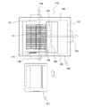
図1は、本発明の実施例の空調換気システムの構成図である。
図示するように、高気密高断熱住宅である建物(図示せず)に設置された空調換気システム100は、建物内で複数に区画された部屋105、浴室106、トイレ107、洗面所108、台所(図示せず)、屋根裏(図示せず)、廊下(図示せず)、床下(図示せず)等の居室及び非居室を空調し、換気する。この場合、居室とは居住、執務、作業、集会、娯楽その他これらに類する目的のために継続的に使用する室を言い、非居室はそうではない室を言うが、居室として判断が難しい用途の室は、利用実態に応じて判断すればよい。FIG. 1 is a block diagram of an air conditioning ventilation system according to an embodiment of the present invention.
As shown in the figure, the air-
居室及び非居室の複数の区画は、建物ごとに個別に設定できる。
屋根裏、床下、階段下(図示せず)、階段の踊り場(図示せず)、機械室(図示せず)等の非居室に、リターン区画101が設けられている。リターン区画101内には、外気を導入する外気導入口121、複数の吸込口120を有する送風部103、複数の部屋105からのリターン空気を導入するリターン口122、室外に設置された空調室外機114と冷媒配管及び電気配線で接続された複数の空調部102が設けられている。
送風部103と居室である複数の部屋105の天井に設けられた吸気部123とは、複数のダクト104で接続されている。各部屋105のドアのアンダーカットなどの排気部124は、非居室である廊下、階段ホール(図示せず)、玄関(図示せず)と、又は、ダクト(図示せず)と連結され、それらは、リターン区画101に設けられたリターン口122と連結している。Multiple compartments for living and non-living rooms can be set individually for each building.
The
上記構成において、空調部102、送風部103が運転すると、空調部102により空調されたリターン区画101内の空気を、送風部103により、ダクト104を通して送風し、複数の部屋105の吸気部123から空調空気が吹き出し、各部屋105を空調する。空調後の空気は、各部屋105の排気部124から、廊下、階段ホール、玄関、又は、ダクトを通って、リターン口122から、リターン区画101に戻って、空調部102により、空調される。
空調部102は、空調室外機114と冷媒配管で連結された熱交換器(図示せず)と送風機(図示せず)を有し、送風部103は、ファン(図示せず)とモーター(図示せず)を有している。
本実施例では、リターン区画101内の送風機を、空調部102の送風機と送風部103とに分けているが、熱交換器で熱交換させるための空調送風機能と各部屋105に送風する搬送機能が効果的に作用するならば、どのような送風機の構成でも構わない。
本実施例では、リターン区画101は壁と断熱材で覆われ密閉された空調室であるが、板金や断熱材で覆われたコンパクトな筐体であってもよく、空調部102と送風部103の位置関係で、空調前後の空気が混ざらなければ、一部が解放された階段室や廊下や筐体でもよい。In the above configuration, when the air-conditioned
The air-
In this embodiment, the blower in the
In this embodiment, the
浴室106やサニタリー109のドアのアンダーカットなどの各換気吸気部125は、複数の部屋105の排気部124、廊下、階段ホール、又は玄関と連結されている。サニタリー109は、トイレ107や洗面所108である。部屋105及び台所は居室であり、浴室106、トイレ107、洗面所108、納戸(図示せず)等の収納室、屋根裏、床下、廊下、階段ホール、及び玄関は非居室である。
Each
浴室106、トイレ107、及び洗面所108に設けられた各換気排気部126と、通常の分岐ダクトより大きい内容積をもった合流チャンバー110とは、ダクト127で接続され、合流チャンバー110とフィルターボックス129とは、ダクト128で接続され、フィルターボックス129と全熱熱交素子131を有する熱交換ユニット111とは、ダクト130で接続され、熱交換ユニット111と外壁140に設けられた排気口113とは、ダクト135で接続されている。
本実施例では、トイレ107及び洗面所108に設けられた各換気排気部126と合流チャンバー110とがダクト127で接続されているが、納戸又は台所に設けられた各換気排気部(図示せず)と合流チャンバー110とをダクトで接続してもよい。また、本実施例では、合流チャンバー110は、浴室106の天井の上に設け、浴室106の換気排気部126と合流チャンバー110の換気排気口(後述)とは、直接空気が流れるよう接続されている。しかしながら、合流チャンバー110を浴室106の天井裏や、トイレ107、洗面所108などのサニタリー109、納戸又は台所の天井裏に設け、浴室106の換気排気部と合流チャンバー110の換気排気口(後述)をダクトで接続してもよい。また、浴室106、トイレ107、洗面所108、納戸、又は台所に設けられた送風機を有する換気扇(図示せず)の出口部(図示せず)と合流チャンバー110の換気排気口(後述)をダクトで接続してもよい。また、合流チャンバー110を浴室106ではなく、トイレ107、洗面所108、納戸、又は台所の天井の上に設け、各換気排気部126と合流チャンバー110の換気排気口(後述)と直接空気が流れるように接続してもよい。Each ventilation /
In this embodiment, each ventilation /
外壁140に設けられた給気口134とフィルターボックス132とは、ダクト133で接続され、フィルターボックス132と熱交換ユニット111とは、ダクトで接続され、熱交換ユニット111とリターン区画101の外気導入口121とは、ダクトで接続されている。
上記構成において、熱交換ユニット111が運転すると、複数の部屋105の排気部124から、廊下、階段ホール、玄関、ダクトを通して、空調後のリターン空気の一部が、浴室106とその他の部屋であるトイレ107や洗面所108などの各換気吸気部125からサニタリー109に流入する。サニタリー109の湿気や臭いを含んだ空気と混ざった換気空気が各換気排気部126からダクト127等を通じて合流チャンバー110に流入し、合流チャンバー110内部で湿気や臭いが混合し、薄められ、ダクト128を通して、フィルター(図示せず)が入ったフィルターボックス129を通過する。そうすることで、空気の水蒸気や、それに含まれる化学的成分が減った浴室106等の換気空気が、ダクト130を通って、熱交換ユニット111に流入する。The
In the above configuration, when the
室外112からの空気(外気)は、給気口134から給気され、ダクト133、外気を浄化するフィルターが入ったフィルターボックス132を通って、熱交換ユニット111に流入して浄化される。熱交換ユニット111では、換気空気が、全熱熱交素子131により、外気と全熱交換され、ダクト135を通って、排気口113から、室外112に排出される。
排気口113は、空調室外機114の熱交換器115の吸込み側の位置に設けられ、排出口113からの換気空気が漏れなく、熱交換器115に吸い込まれるように、空調室外機114と外壁140との間に隔壁141が設けられている。
上記構成において、排出口113からの熱交換ユニット111で回収されなかった全熱の換気空気と外気が合流して、熱交換器115に吸い込まれる。
熱交換ユニット111からの新鮮空気と空調後のリターン空気が、リターン区画101内で、空調部102により空調され、空調された空気が、送風部103により、複数の部屋105に送られ、部屋105を空調する。その空調後の空気の一部が、浴室106とその他の部屋に送られ、空調された空気が、浴室106の空気とその他の部屋の空気と置き換わりながら、浴室106の空気とその他の部屋の空気が排気され、それらが合流し、混合される。それにより、浴室106の空気の相対湿度よりも合流後の空気の相対湿度が下がって、合流後の空気は、熱交換ユニット111に流入し、外気と熱交換して室外112に排出される。よって、特に入浴時の浴室106の熱を回収でき、全熱熱交素子131の結露が少なくなり、その短命化を防止でき、浴室106内のカビを防止できる。従って、省エネで、快適で、きれいな空気を実現できる空調換気システム100が得られる。
また、サニタリー109、納戸、又は台所をその他の部屋としたので、浴室106より湿気が少ない空間であるトイレ107、洗面所108、納戸、又は台所などの空気を合流させることで、合流換気空気に対する臭いや湿気の比率を下げて、部屋105を経ないで、合流空気を直接的に熱交換ユニット111に流入させる。よって、より多くの熱を回収しながら、全熱熱交素子131の結露を少なくし、その短命化を防止する。従って、部屋105への臭いや湿気が移動しない空調換気システム100が得られる。
また、浴室106、サニタリー109、納戸、又は台所の各々の換気空気が、通常の分岐ダクトより大きい内容積をもった合流チャンバー110で、合流する。よって、合流チャンバー110の内容積が大きいほど、合流換気空気に対する臭いや湿気の比率が下がり、より全熱熱交素子131の結露が少なくなり、その短命化を防止できる。従って、施工性の良い空調換気システム100が得られる。The air (outside air) from the outdoor 112 is supplied from the
The
In the above configuration, the ventilation air of all the heat not recovered by the
The fresh air from the
Further, since the sanitary 109, the storage door, or the kitchen is used as another room, the air in the
Further, the ventilation air of each of the
なお、合流チャンバー110の内容積は、大きければその効果も大きいが、施工スペース等の制約もある。そのため、家全体の換気風量と浴室106からの換気風量、浴室106、トイレ107、洗面所108などのサニタリー109、納戸、又は台所の通常の平均湿度と浴室106の入浴時等の高湿度時の湿度により、決定するのがよい。例えば、床面積100m2、天井高さ2.5mの換気回数0.5回/hの場合、24時間換気風量は125m3/hであり、浴室106、トイレ107、洗面所108の各風量が、35m3/h、45m3/h、45m3/hであり、平均湿度が50%以下、入浴時の高湿度時の湿度が80%以上の場合、浴室106から合流チャンバー110に流入する風量35m3/h(0.01m3/S)が、1秒間に一回合流チャンバー110から排出されるように、合流チャンバー110の最低内容積は、0.01m3以上の、幅250mm×奥行250mm×高さ250mmで0.016m3とする。浴室106からの高湿度な換気空気の風量に対し、サニタリー109等の比較的低湿度な換気空気の風量が多いほど、合流チャンバー110の容積を小さくでき、逆に、その風量が少ないほど合流チャンバー110の容積を大きくするか、合流チャンバー110を複数個設ける必要がある。If the internal volume of the merging
また、合流チャンバー110の浴室106からの換気空気の換気排気口(後述)に、浴室106に設けた浴室用換気扇(図示せず)の出口部をダクトで接続した場合、浴室用換気扇の送風機(図示せず)が運転すると、浴室106からの換気空気が、ダクトの抵抗に関係なく、安定して、合流チャンバー110に流入し、浴室106を換気でき、また、合流チャンバー110の設置しやすい場所を選択できる。従って、施工性が良い空調換気システム100が得られる。
また、浴室106、トイレ107、洗面所108等のいずれかのサニタリー109、納戸、又は台所の天井(図示せず)に、合流チャンバー110を設けたので、浴室106、サニタリー109、納戸、又は台所の換気排気部126と合流チャンバー110の換気排気口(後述)とをダクトを介さず、直接接続できる。よって、ダクトの抵抗に関係なく、他の換気扇(図示せず)が不要で、安定して、浴室106、サニタリー109、納戸、又は台所を換気できる。従って、浴室106、サニタリー109、納戸、又は台所の天井下からメンテナンスが可能な空調換気システム100が得られる。Further, when the outlet portion of the bathroom ventilation fan (not shown) provided in the
Further, since the
空調部102の能力、台数を建物の空調負荷により選定する。リターン区画101では、外気とリターン空気を空調部102で、各部屋105の目標温度に対し、冷房時5K以内、暖房時10K以内の温度差となるよう空調する。その空調空気を複数の送風部103で、複数のダクト104を通して、複数の部屋105の天井に設けられた吸気部123から送風することにより、各部屋105を快適な温度に空調する。そして、各部屋105の排気部124から廊下や階段ホールや玄関やダクトを通して、空調後のリターン空気が、リターン口122からリターン区画101に戻る。
本実施例では、送風部103から複数のダクト104を通して、各部屋105に送風するが、複数のダクト104ではなく、一本のダクト104を途中から分岐してもよい。また、ダクト104の代わりに、建材で区画された送気用区画部を通して送風してもよい。また、直接的に、部屋105に送風するのではなく、天井裏空間や床下空間や廊下や階段ホールや玄関を経由して、間接的に部屋105に送風してもよい。さらに、空調する区画としては、浴室106、サニタリー109、納戸、又は台所も含まれ、積極的に空調したい区画を選定すればよい。The capacity and number of
In this embodiment, the air is blown from the
夏季は、冷房された室内空気(換気空気)と室外空気(外気)が熱交換ユニット111で熱交換されても、全熱でも通常50%から70%程度しか熱交換できない。従って、室外空気より全熱の少ない(温度、湿度が低い)換気空気が排気口113から排出され、その空気と室外空気が合流し、室外空気よりも全熱の少ない空気となって、凝縮器である熱交換器115を通過させ、冷媒に全熱交換させる。また、冬季は、暖房された室内空気(換気空気)と室外空気(外気)が熱交換ユニット111で熱交換されても、全熱でも通常60%から80%程度しか熱交換できない。従って、室外空気より全熱の多い(温度、湿度が高い)換気空気が排出口113から排出され、その空気と室外空気が合流し、室外空気よりも全熱の多い空気となって、蒸発器である熱交換器115を通過させ、冷媒に全熱交換させる。
このように、熱交換ユニット111から排出された換気空気を室外112に排出する排気口113を熱交換器115の吸込み側の位置に設けたことにより、熱交換ユニット111で回収しきれなかった熱をさらに回収し、より省エネな空調換気システム100が得られる。In the summer, even if the cooled indoor air (ventilation air) and the outdoor air (outside air) are heat-exchanged by the
As described above, by providing the
なお、本実施例では、排気口113は、熱交換器115の吸込み側の位置に設けられているが、ダクト135を2分岐して、排気口113を2か所に設け、一方の排気口113を空調室外機114の吸込み側の位置から離して設置してもよい。なお、各排気口113には開閉ダンパーを接続する。そして、空調部102の運転モードと室外温度と換気空気の温度により、空調室外機114の吸込み側の位置に設置した排気口113と、空調室外機114の吸込み側の位置から離して設置した排気口113とを切り替えて使用することもできる。例えば、夏季の夜間で、冷房運転中に、室外温度が25℃であり、換気空気の温度が30℃で、外気温度より高い場合、熱交換ユニット111で熱交換され排出される空気が27℃以上となる可能性が高い。従って、開閉ダンパーを開閉して、空調室外機114の吸込み側の位置から離した排気口113から、27℃以上の換気空気を排出することにより、熱交換器115に吸い込まれる空気の温度を25℃の温度の低い外気とし、凝縮器である熱交換器115内の冷媒により多くの熱交換を行わせ、より省エネルギーとすることが可能である。
In this embodiment, the
建物全体の換気空気の流れは、リターン区画101内で、新鮮な外気が空調空気と一緒に空調部102で攪拌、混合され、均一な温度、空質となる。そして、混合された空気は複数の送風部103により大風量で、部屋105などの居住ゾーンに送られる。居住ゾーンにおいて空調後の人が呼吸した空気の一部は、湿気や臭いが発生しやすいサニタリーゾーンに移動して合流し、建築基準法上の24時間換気として必要な換気風量以上で、熱交換ユニット111により、室外112に排出される。
そのため、複数の送風部103の合計風量が空調部102の送風機の風量よりも多く、かつ空調部102の送風機の風量が熱交換ユニット111の換気風量より多いと非常に効果的である。
空調のために必要な各送風部103の送風量は、部屋2.5m3あたり少なくとも13m3/h以上、理想的には20m3/h程度が望ましく、部屋105の大きさや負荷に応じて送風量を調整する。
空調部102の送風機の最適空調風量:Vqは、各送風部103の合計送風量:Vhの50%以下の風量であり、多くても70%以下の風量であり、空調部102が空調負荷に対応して能力を発揮できる風量である。
建物の床面積、天井高さや空調負荷によるが、例えば、建物の床面積約100m2、天井高さ2.5mで、4kW相当の冷房能力をもつ空調部102を設置すると、複数の送風機103の合計風量Vhは1200m3/hで、空調部102の送風機の最適空調風量Vqは700m3/h、熱交換ユニット111の24時間換気風量は、換気回数0.5回/hで、125m3/hとなる。
このように、複数の送風部103の合計風量が空調部102の風量及び熱交換ユニット111の換気風量より多いことにより、効率的に空調空気が家全体の空気を攪拌しながら、新鮮空気が導入され、CO2や湿気や臭い等を含んだ空気が排出される空調換気システム100が得られる。
換気風量については、入浴時に一時的に湿度が増えたり、トイレ107使用により臭いが増えたり、燃焼系の暖房機器を運転したときなど、局所換気として、風量を増やしてもよい。例えば、24時間換気風量125m3/hに対し、250m3/hに増やす。In the flow of the ventilation air in the entire building, fresh outside air is agitated and mixed with the conditioned air in the
Therefore, it is very effective when the total air volume of the plurality of
The amount of air blown by each
The optimum air-conditioning air volume of the blower of the air-conditioning unit 102: Vq is the air volume of 50% or less of the total air-conditioning volume of each air-conditioning unit 103: Vh, and at most 70% or less. It is the air volume that can exert its ability correspondingly.
Depending on the floor area, ceiling height and air conditioning load of the building, for example, if an
As described above, since the total air volume of the plurality of
Regarding the ventilation air volume, the air volume may be increased as local ventilation, such as when the humidity temporarily increases during bathing, the odor increases due to the use of the
本実施例では、部屋105を空調しているが、台所などその他の居室を空調してもよく、空調空気の流れを合理的にするためや、より快適性を向上させるために、非居室を空調してもよい。また、本実施例では、新鮮空気である外気を、臭いや湿気等が発生しにくい部屋105(居間、寝室、書斎など)のいわゆるクリーンゾーンに導入し、廊下、玄関、階段(図示せず)等を通って、臭いや湿気等が発生しやすい浴室106、サニタリー109、納戸、又は台所等のいわゆるダーティゾーンへ流し、その後室外112に排気している。しかしながら、新鮮空気である外気を、部屋105(居間、寝室、書斎など)のいわゆるクリーンゾーン、又は浴室106、サニタリー109、納戸、若しくは台所等のダーティゾーンに導入し、その後、室外112に排気してもよい。
In this embodiment, the
また、本実施例では、浴室106、トイレ107、洗面所108に換気排気部126が設けられているが、複数の部屋105、台所などその他の居室、屋根裏、床下、階段下、階段の踊り場、機械室等の非居室、リターン区画101に、換気排気部126を設け、各空間の空調空気や外気により空調、換気された後のリターン空気を、ダクトにより、合流チャンバー110、フィルターボックス129を経由させ、熱交換ユニット111に流入させてもよい。浴室106、サニタリー109の湿気や臭いを含んだ空気は、合流チャンバー110、フィルターボックス129、ダクトを通って、居室や非居室、リターン区画101からの湿気や臭いが少ない、より多くの空気と合流することで、合流換気空気に対する臭いや湿気の比率がさらに下がって、熱交換ユニット111に流入するからである。そういった場合は、熱交換ユニット111に流入する前に、各換気排気部126につながったダクトの合流部に合流チャンバー110を複数台設けると、その効果はさらに高まる。
Further, in this embodiment, the ventilation /
また、本実施例では、浴室106やサニタリー109であるトイレ107や洗面所108は、それぞれ別の空間としており、それぞれに換気排気部126を設けている。しかしながら、諸外国のように、浴室とトイレ、洗面所が一つの空間となっている場合や、浴室に浴槽がなく、シャワーだけの場合でも、各住宅設備の使用により発生する湿度と臭い等は排気されて、その熱は回収される。従って、本システムは有効であり、その場合、換気排気部126は、風量や空間内の湿度、臭いの分布に合わせて、まとめて一つであってもよい。
Further, in this embodiment, the
また、本実施例では、住宅内で、湿度が高く、臭いが発生する場所として、浴室106を主に排気する空間とし、サニタリー109も同様に排気する空間としたが、地下室や床下、乾燥室、納戸、汚物室など、湿度が高く、臭いが発生しやすい空間から、主に排気しても、本システムは有効である。
Further, in this embodiment, as a place where the humidity is high and odor is generated in the house, the
図2は、空調換気システム100が設置された建物のサニタリーの縦断面図である。
図示するように、浴室106の隣に、洗面所108、トイレ107が設けられ、換気排気部126が各天井152に設けられている。浴室106の換気排気部126は、浴室106の天井152に設けられた合流チャンバー110の換気排気口(図示せず)と接続したグリル150に設けられ、フィルター151がグリル150の換気排気部126の下流側に、浴室106から抜き差し自在に設けられている。換気排気部126と合流チャンバー110とは、ダクト127と換気排気口で接続され、合流チャンバー110と、フィルターが入ったフィルターボックス129とは、ダクト128で接続されている。FIG. 2 is a vertical sectional view of a sanitary building in which the air
As shown in the figure, a
図3は、空調換気システムの合流チャンバーの縦断面図で、図4は、合流チャンバーの底面図である。
図示するように、合流チャンバー110の底面153に、浴室106からの換気空気の換気排気部126を備えたグリル150が設けられている。換気空気に含まれた埃や湿気や化学成分を除去するフィルター151がグリル150の換気排気部126の下流側に、下方から抜き差し自在に設けられている。フィルター151の下流には、合流チャンバー110への流入口である換気排気口154が設けられている。図4では、フィルター151は、横に抜き出す、差し込む方式が示さているが、抜き出す、差し込む方向は他の方向でもよく、下へ引き出す、上にはめ込む方式でもよい。そして、トイレ107、洗面所108からの換気空気の換気排気部126と接続されたダクト127は、合流チャンバー110の両側面155に設けられた換気排気口156に接続される。合流チャンバー110の側面155の一部である後面157に設けられた出口部158と、フィルターボックス129は、ダクトによって接続される。FIG. 3 is a vertical cross-sectional view of the merging chamber of the air conditioning ventilation system, and FIG. 4 is a bottom view of the merging chamber.
As shown in the figure, a
上記構成により、浴室106からの換気空気が、フィルター151のメッシュ(図示せず)等の微小な隙間を通過時に、その換気空気中の埃や大きな水蒸気がフィルター151に付着することによって、換気空気中の埃や湿気や、それらに含まれる化学的成分や臭いが取られる。そして、その換気空気は、トイレ107、洗面所108からの換気空気と合流チャンバー110内で混合され、さらに浴室106からの湿気や臭いが薄められ、合流チャンバー110の出口部158から、ダクトにより、フィルターボックス129に流入する。
フィルター151により、浴室106からの換気空気中の大きな水蒸気や、それに含まれる化学的成分の熱交換ユニット111への流入の防止が可能な空調換気システム100が得られる。With the above configuration, when the ventilation air from the
The
なお、フィルター151のメッシュの大きさや厚み、面積、材質等は、通過する空気の量、それに含まれる埃や水蒸気、それに含まれる化学的成分によって、最適な仕様に、適宜変えることが可能である。
また、フィルター151は、合流チャンバー110の下方から取り外し可能である。従って、フィルター151に埃や水蒸気、それに含まれる化学的成分が多く付着した場合、フィルター151を取り外して、清掃することで、性能を維持することが可能である。
これにより、浴室106からフィルター151のメンテナンスが容易な空調換気システム100が得られる。The size, thickness, area, material, etc. of the mesh of the
Further, the
As a result, the air-
合流チャンバー110の内部には、混合部163と合流後の換気空気の出口部158への流路の途中に、壁部160を有する。壁部160は合流チャンバー110の両側面155まで延び、天面161との間に隙間162を設けている。混合部163では、浴室106からの換気空気とトイレ107からの換気空気と洗面所108からの換気空気が合流、混合する。混合部163はサニタリー109からの換気空気を排気する各換気排気口154、156と壁部160の間に設ける。
上記構成において、入浴時の浴室106の高湿換気空気が、他のサニタリー109の換気空気と混合して、より低湿度の換気空気となって、熱交換ユニット111に流入する空調換気システム100が得られる。
また、混合部163で合流、混合後に、フィルター151を通り抜けた換気空気中の比較的大きな水蒸気や、それに含まれる化学的成分が、壁部160に衝突して、重力により下方に留まり、隙間162を越えられない。それにより、合流後の換気空気中の比較的大きな水蒸気や、それに含まれる化学的成分の熱交換ユニット111への流入の防止が可能な空調換気システム100が得られる。
なお、壁部160と隙間162の面積は、通過する換気風量と通過する空気の湿度により、決定するのがよい。Inside the merging
In the above configuration, the high humidity ventilation air of the
Further, after merging and mixing at the mixing
The area between the
壁部160には、複数の小孔170を有する。
上記構成において、合流換気空気の壁部160通過時に、換気空気の比較的小さな水蒸気は、壁部160の小孔170の周壁(図示せず)に付着する。換気空気は、換気空気内の水分を減少させながら、小孔170を通過するため、圧力損失が少なくなり、換気風量が増加する。
これにより、合流後の空気の水蒸気や、それに含まれる化学的成分の熱交換ユニット111への流入の防止が可能で、圧力損失の少ない安定した換気風量を維持する空調換気システム100が得られる。
なお、小孔170の形状、断面積、個数等は、換気風量と通過する空気の湿度と圧力損失により、決定するのがよい。The
In the above configuration, when the combined ventilation air passes through the
As a result, it is possible to prevent the water vapor of the merged air and the chemical components contained therein from flowing into the
The shape, cross-sectional area, number, etc. of the
合流チャンバー110及び、壁部160の下部には、ドレンパン165が設けられている。ドレンパン165は、浴室106側からグリル150を外した状態で、脱着可能である。
上記構成において、壁部160や小孔170に付着した水蒸気は、ドレン水164となって、壁部160の下部に設けたドレンパン165に溜まり、結果的に換気空気に含まれる水分やそれに含まれた化学成分の量は減少する。ドレンパン165にドレン水が溜まるため、浴室106への滴下が防止でき、浴室106側からメンテナンスが可能である。ドレン水164が溜まったら、ドレンパン165を取り外して、ドレン水164を捨て、再度取り付けることが可能である。また、ドレンパン165には、ドレンホースが接続可能で(図示せず)、オーバーフローを防止し、連続排水とすることもできる。
合流チャンバー110のサニタリー109からの換気空気の各換気排気口154、156に、平板3枚から2枚をスライドさせる風量調整部171を有する。
上記構成において、平板をスライドさせて、換気排気口154、156の面積を変更することにより、サニタリー109の各必要換気風量や換気空気の湿度、臭い等に対応した換気風量に調整可能である。従って、家全体の換気を行いながら、サニタリー109の湿度、臭い等を減らし、入浴時の湿気の熱交換ユニット111への流入を減らした空調換気システム100が得られる。
なお、本実施例では、風量調整部171は、平板数枚からなるスライド式で、浴室106から手動で調整可能であるが、モーターで可動させてもよい。また、風量調整部171は、ダンパーの回転角度によって調整して、同様にモーターで可動させてもよい。A
In the above configuration, the water vapor adhering to the
Each
In the above configuration, by sliding the flat plate and changing the area of the
In this embodiment, the air
サニタリー109の各必要換気風量や換気空気の湿度、臭い等に対応した換気風量とは、例えば、建物全体の24時間換気風量は、その床面積より、125m3/hであり、通常は浴室55m3/h、トイレ35m3/h、洗面所35m3/hの場合に、浴室35m3/h、トイレ45m3/h、洗面所45m3/hである。これは、浴室106は入浴時に高温高湿の換気空気となるため、浴室106の換気風量を、トイレ107、洗面所108の換気風量の同等以下とするためである。
風量調整部171により、浴室106の換気風量をその他のサニタリー109の換気風量の同等以下とするため、入浴時の浴室106の湿気の熱交換ユニット111への流入をさらに減らした空調換気システム100が得られる。The ventilation air volume corresponding to each required ventilation air volume, the humidity of the ventilation air, the odor, etc. of the sanitary 109 is, for example, the 24-hour ventilation air volume of the entire building is 125 m 3 / h from the floor area, and usually the bathroom is 55 m. In the case of 3 / h, toilet 35m 3 / h, and washroom 35m 3 / h, the bathroom is 35m 3 / h, the toilet is 45m 3 / h, and the washroom is 45m 3 / h. This is because the
The air-
合流チャンバー110内の換気排気口154と出口部158との距離が、換気排気口156と出口部158との距離よりも長くなっている。
上記構成において、浴室106以外のサニタリー109からの換気空気は、浴室106からの換気空気より早く、スムーズに出口部158に到達するので、浴室106からの換気空気内の水蒸気が減りやすく、浴室106からの風量も減らすように調整しやすい空調換気システム100が得られる。The distance between the ventilation /
In the above configuration, the ventilation air from the sanitary 109 other than the
浴室106の天井152に合流チャンバー110を有し、換気排気口154を合流チャンバー110の底面153に有し、換気排気口156を合流チャンバー110の両側面155に有し、出口部158を後面157に有している。
上記構成において、湿気をより多く含んだ浴室106からの換気空気が、合流チャンバー110の下方から流入し、湿度が比較的低いトイレ107、洗面所108からの換気空気が、合流チャンバー110の両側方から浴室106からの換気空気の流入を塞ぐように合流する。そのため、入浴時での浴室106の高湿度な換気空気が合流チャンバー110に流入しても、部分的に風速が遅くなることから、水蒸気がその重力により、下方に留まり、壁部160を乗り越えられない。従って、出口部158から排出する合流空気をより低湿度にすることが可能な空調換気システム100が得られる。The
In the above configuration, the ventilation air from the
なお、本実施例では、合流チャンバー110の底面153に、換気排気口154が、合流チャンバー110の両側面155に、換気排気口156が、後面157に出口部158が設けられているが、換気空気の流れが合理的であれば、合流チャンバー110の底面153、4つの側面155(後面157含む)及び天面161のどこに、換気排気口154、156、出口部158が配置されていてもよい。また、換気排気口154、156、出口部158の数も、接続する各空間の換気排気部126の数や風量に合わせて増減させてもよい。
In this embodiment, the ventilation /
また、本実施例では、合流チャンバー110の底面153に、浴室106からの換気空気の換気排気部126が設けられ、トイレ107、洗面所108からの換気空気の換気排気部126と接続されたダクト127は、合流チャンバー110の両側面155に設けられた換気排気口156に接続される。しかしながら、住宅内では、湿度が高く、臭いが発生する場所として、浴室106やサニタリー109以外の地下室や床下、乾燥室、納戸、汚物室などがある。各空間の換気排気部を、合流チャンバー110の底面153や両側面155等と接続しても、本システムは有効である。また、合流チャンバー110に接続した各空間の各必要換気風量や換気空気の湿度、臭い等に対応した換気風量となるように、各風量調整部171を調整してもよい。
Further, in the present embodiment, the ventilation /
フィルターボックス129は、合流チャンバー110と熱交換ユニット111を接続するダクト128とダクト130の間で、天井裏に設けられる。フィルターボックス129は、下方に点検口を設け(図示せず)、フィルターを取り外し可能としている。このフィルターは、合流チャンバー110のフィルター151よりも細かい埃や、水蒸気、それに含まれる化学的成分が取れるように、メッシュの大きさや厚み、面積、材質等を、最適な仕様に変えることが望ましい。また、フィルター151で相当量の埃、水蒸気、化学的成分を取ることが可能であれば、それと同等でもよく、また、設けなくてもよい。
フィルターが、点検口を通して、フィルターボックス129の下方から取り外し可能であるので、フィルターに埃や水蒸気、それに含まれる化学的成分が多く付着した場合、それを取り外して、清掃することで、性能を維持することが可能である。
これにより、さらに低湿度で化学成分の少ない換気空気が熱交換ユニット111に流入し、フィルターボックス129からフィルターのメンテナンスが容易な空調換気システム100が得られる。The
The filter can be removed from below the
As a result, the ventilation air having a lower humidity and less chemical components flows into the
図5は、空調換気システムの熱交換ユニットの水平断面図で、(a)は熱交換気モード時、(b)は普通換気モード時を表す。
図示するように、熱交換ユニット111内に、新鮮な外気と空調後の換気空気の全熱交換を行う全熱熱交換素子131を備え、外気を吸い込むフィルターボックス132と外気入口部180とはダクトで接続され、外気出口部182とリターン区画101の外気導入口121とはダクトで接続され、外気入口部180と外気出口部182との間の風路(図示せず)には、順に、全熱熱交換素子131と給気送風機181が設けられている。
一方、換気空気を吸い込むフィルターボックス129と換気空気入口部184とはダクト130で接続され、換気空気出口部186と換気空気を排出する排気口113とはダクト135で接続され、換気空気入口部184と換気空気出口部186との間の風路(図示せず)には、順に、バイパスダンパー187と全熱熱交換素子131と排気送風機185が設けられている。
上記構成において、フィルターボックス132で浄化された外気は、ダクトを通って、外気入口部180から、熱交換ユニット111に流入する。その後、外気は、全熱熱交換素子131を通って、給気送風機181により、外気出口部182、ダクト、外気導入口121からリターン区画101に導入される。
一方、空調後の換気空気は、フィルターボックス129、ダクト130を通って、換気空気入口部184から、熱交換ユニット111に流入する。その後、換気空気は、全熱熱交換素子131を通って、排気送風機185により、換気空気出口部186、ダクト135を通って、排気口113から、室外112に排出される。5A and 5B are horizontal cross-sectional views of the heat exchange unit of the air conditioning ventilation system, where FIG. 5A shows the heat exchange air mode and FIG. 5B shows the normal ventilation mode.
As shown in the figure, the
On the other hand, the
In the above configuration, the outside air purified by the
On the other hand, the ventilated air after air conditioning flows into the
換気空気入口部184と換気空気出口部186との間には、全熱熱交換素子131を通る風路と並行して、バイパス風路189が設けられている。バイパスダンパー187はモーター188により回転する。バイパスダンパー187は、換気空気を全熱交換素子131に通す熱交換モードと、全熱熱交換素子131をバイパスさせ、バイパス風路189に通す普通換気モードとに切り替え可能である。
このように、熱交換ユニット111が、バイパスダンパー187により、換気空気を全熱熱交換素子131をバイパスさせる普通換気モードと全熱熱交換素子131を通過させる熱交換気モードに切り替えられることにより、冬季の入浴時に熱交換ユニット111を普通換気モードで運転し、より全熱熱交換素子131への結露による短命化を防止できる空調換気システム100が得られる。A
In this way, the
また、熱交換ユニット111の換気空気入口部184付近に温度検出部190と湿度検出部191を有し、外気入口部180付近に外気温度検出部192を有する。また、温度検出部190、湿度検出部191と外気温度検出部192での検出値により、バイパスダンパー187をモーター188により、普通換気モードと熱交換気モードに切り替える制御部193を有する。
制御部193は、通常は、熱交換モードで熱交換ユニット111を運転し、換気空気を全熱熱交換素子131を通過させて、外気と熱交換させる。冬季の入浴時など、外気温度検出部192で検出した温度が10℃以下で、温度検出部190で検出した温度が20℃以上で、湿度検出部191で検出した湿度が70%以上の時、制御部193は、全熱熱交換素子131で、換気空気と外気を熱交換させると、全熱熱交換素子131が結露しやすいと判断して、モーター188を制御して、バイパスダンパー187を熱交換モードから普通換気モードに切り替える。そうすることで、湿気の多い換気空気を全熱熱交換素子131をバイパスさせ、バイパス風路189を通過させ、全熱熱交換素子131の結露を防止し、その短命化を防止する。
また、制御部193は、夏季の夜間で、外気温度検出部192で検出した温度が25℃以下で、温度検出部190で検出した温度が25℃以上の時、全熱熱交換素子131で、換気空気と外気を熱交換させると、外気の温度が上がり、エネルギーを余分に費やし、快適性も損なう。よって、外気と熱交換させないよう、モーター188を制御して、バイパスダンパー187を熱交換モードから普通換気モードに切り替え、外気より高い温度の換気空気を全熱熱交換素子131をバイパスさせ、バイパス風路189を通過させる。そうすることで、全熱熱交換素子131での外気の温度の上昇を防止し、省エネルギーで快適性を向上させる。
このように、自動で、普通換気モードと熱交換気モードに切り替えでき、利便性の高い空調換気システム100が得られる。Further, the
Normally, the
Further, the
In this way, it is possible to automatically switch between the normal ventilation mode and the heat exchange air mode, and a highly convenient air-
本実施例では、温度検出部190を設けたが、これを設けず、外気温度検出部192で検出した温度が10℃以下で、湿度検出部191で検出した湿度が80%以上の時、全熱熱交換素子131が結露しやすいと判断して、普通換気モードに切り替えてもよい。
また、リモコン(図示せず)を設け、手動で熱交換モード、普通換気モードを切り替えるようにしてもよい。
また、外気温度検出部192で検出した温度が10℃以下などの具体的な温度、湿度については、一例である。システムの構成や設置環境等により。最適な温度、湿度は変わるため、リモコンなどで、スライドスイッチ(図示せず)により、使用者が適宜変更可能としてもよい。
また、本実施例の全熱熱交換素子131の構造、材質は、室外112に排出する換気空気の水分は、建物内に導入する外気に適当に移動するが、臭いは移動しにくいものがよい。例えば、全熱熱交換素子131には、活性炭などの吸着性材料を含有するのが望ましい。また、空気や臭いを通さないガスバリア性を有する湿度透過膜、例えば、ナノファイバーを基材とした薄膜透湿樹脂等により、全熱熱交素子131を構成すると、温度、湿度は回収しながら、臭いや雑菌等は戻さないで排気できる。
なお、結露や臭いが非常に多い環境下で全熱熱交換素子131を使用する場合、熱交換効率が悪く、ドレン水164の排水工事が必要となるが、全熱熱交換素子131の代わりに、顕熱熱交換素子を使用してもよい。顕熱熱交換素子であっても、従来そのまま排気していた浴室106等の顕熱は回収でき、かつ湿度低下により、素子結露が少なくなるため、劣化が防止され、寿命が長くなる。In this embodiment, the
Further, a remote controller (not shown) may be provided to manually switch between the heat exchange mode and the normal ventilation mode.
Further, the specific temperature and humidity such that the temperature detected by the outside air
Further, as for the structure and material of the total
When the total
建物内全体の効率的な空調及び換気の流れを作り出すことができるシステムであり、サニタリーや地下室、乾燥室、汚物室などの湿度が高く、臭いが発生する空間がある建物であれば、床面積の大きい商業施設や病院などの建物の空調換気にも適用できる。 It is a system that can create an efficient air conditioning and ventilation flow in the entire building, and if the building has a space with high humidity and odor such as sanitary, basement, drying room, filth room, etc., the floor area It can also be applied to air conditioning and ventilation of buildings such as large commercial facilities and hospitals.
100 空調換気システム
101 リターン区画
102 空調部
103 送風部
104 ダクト
105 部屋
106 浴室
107 トイレ
108 洗面所
109 サニタリー
110 合流チャンバー
111 熱交換ユニット
112 室外
113 排気口
114 空調室外機
115 熱交換器
120 吸込口
121 外気導入口
122 リターン口
123 吸気部
124 排気部
125 換気吸気部
126 換気排気部
127 ダクト
128 ダクト
129 フィルターボックス
130 ダクト
131 全熱熱交素子
132 フィルターボックス
133 ダクト
134 給気口
135 ダクト
140 外壁
141 隔壁
150 グリル
151 フィルター
152 天井
153 底面
154 換気排気口
155 側面
156 換気排気口
157 後面
158 出口部
160 壁部
161 天面
162 隙間
163 混合部
164 ドレン水
165 ドレンパン
170 小孔
171 風量調整部
180 外気入口部
181 給気送風機
182 外気出口部
184 換気空気入口部
185 排気送風機
186 換気空気出口部
187 バイパスダンパー
188 モーター
189 バイパス風路
190 温度検出部
191 湿度検出部
192 外気温度検出部
193 制御部100 Air
Claims (14)
前記吸気部から、空調空気を前記部屋Aに送風し、
前記空調空気の一部を、前記排気部から、リターン区画に戻し、
前記リターン区画に送風部と空調部とを設け、
前記吸気部と前記送風部を繋ぎ、
前記送風部と前記空調部により、前記部屋Aの目標温度に対し、冷房時5K以内、暖房時10K以内の温度差となる前記空調空気を作って送風し、
浴室と部屋Bに、空気を換気する換気吸気部と換気排気部とを設け、
前記排気部と前記換気吸気部を繋ぎ、
熱交換ユニットにより、
前記空調空気の残りを、前記換気吸気部から、前記浴室と前記部屋Bに流入させ、
前記換気排気部と前記熱交換ユニットの間に合流チャンバーを設け、
前記合流チャンバーにより、前記部屋Bの前記換気排気部からの空気Cを前記浴室の前記換気排気部からの空気Dに合流させ、
前記合流チャンバーの合流空気を室外空気と熱交換して室外に排出し、
前記リターン区画に、前記合流空気と熱交換した後の前記室外空気を導入する
ことを特徴とする空調換気システム。 Intake and exhaust sections are provided in multiple rooms A in the building.
Air-conditioned air is blown from the intake unit to the room A, and the air-conditioned air is blown to the room A.
A part of the conditioned air is returned from the exhaust section to the return section,
A ventilation section and an air conditioning section are provided in the return section.
By connecting the intake unit and the ventilation unit,
The air-conditioning unit and the air-conditioning unit create and blow the air-conditioned air having a temperature difference of 5K or less during cooling and 10K or less during heating with respect to the target temperature of the room A.
A ventilation intake unit and a ventilation exhaust unit for ventilating air are provided in the bathroom and room B.
By connecting the exhaust unit and the ventilation intake unit,
With heat exchange unit
The rest of the conditioned air is allowed to flow into the bathroom and the room B from the ventilation intake unit.
A merging chamber is provided between the ventilation exhaust unit and the heat exchange unit.
The merging chamber allows the air C from the ventilation / exhaust section of the room B to merge with the air D from the ventilation / exhaust section of the bathroom.
The merging air of the merging chamber exchanges heat with the outdoor air and is discharged to the outside.
An air-conditioning ventilation system characterized in that the outdoor air after heat exchange with the combined air is introduced into the return compartment.
前記合流チャンバーの底面に、前記浴室の前記換気排気部を設け、
前記合流チャンバーの側面に、前記部屋Bからの前記換気排気部と繋がった換気排気口と前記熱交換ユニットと繋がった出口部とを設けた
ことを特徴とする請求項1に記載の空調換気システム。 The confluence chamber is provided behind the ceiling of the bathroom .
The ventilation / exhaust section of the bathroom is provided on the bottom surface of the merging chamber.
On the side surface of the merging chamber, a ventilation exhaust port connected to the ventilation exhaust portion from the room B and an outlet portion connected to the heat exchange unit are provided.
The air-conditioning ventilation system according to claim 1 .
ことを特徴とする請求項2に記載の空調換気システム。 A filter is provided in the ventilation / exhaust section of the bathroom of the merging chamber.
The air-conditioning ventilation system according to claim 2 .
Priority Applications (1)
| Application Number | Priority Date | Filing Date | Title |
|---|---|---|---|
| JP2022079137A JP7385309B2 (en) | 2019-12-13 | 2022-05-13 | air conditioning ventilation system |
Applications Claiming Priority (3)
| Application Number | Priority Date | Filing Date | Title |
|---|---|---|---|
| JP2019225554 | 2019-12-13 | ||
| JP2019225554 | 2019-12-13 | ||
| PCT/JP2020/045873 WO2021117768A1 (en) | 2019-12-13 | 2020-12-09 | Air conditioning ventilation system |
Related Child Applications (1)
| Application Number | Title | Priority Date | Filing Date |
|---|---|---|---|
| JP2022079137A Division JP7385309B2 (en) | 2019-12-13 | 2022-05-13 | air conditioning ventilation system |
Publications (3)
| Publication Number | Publication Date |
|---|---|
| JPWO2021117768A1 JPWO2021117768A1 (en) | 2021-06-17 |
| JPWO2021117768A5 JPWO2021117768A5 (en) | 2022-04-13 |
| JP7079046B2 true JP7079046B2 (en) | 2022-06-01 |
Family
ID=76328894
Family Applications (2)
| Application Number | Title | Priority Date | Filing Date |
|---|---|---|---|
| JP2021564000A Active JP7079046B2 (en) | 2019-12-13 | 2020-12-09 | Air conditioning ventilation system |
| JP2022079137A Active JP7385309B2 (en) | 2019-12-13 | 2022-05-13 | air conditioning ventilation system |
Family Applications After (1)
| Application Number | Title | Priority Date | Filing Date |
|---|---|---|---|
| JP2022079137A Active JP7385309B2 (en) | 2019-12-13 | 2022-05-13 | air conditioning ventilation system |
Country Status (3)
| Country | Link |
|---|---|
| US (1) | US20230040056A1 (en) |
| JP (2) | JP7079046B2 (en) |
| WO (1) | WO2021117768A1 (en) |
Citations (4)
| Publication number | Priority date | Publication date | Assignee | Title |
|---|---|---|---|---|
| JP2002257380A (en) | 2001-02-28 | 2002-09-11 | Nice Corp | Air conditioning system |
| JP2005188885A (en) | 2003-12-26 | 2005-07-14 | Matsushita Electric Ind Co Ltd | Compound unit system |
| JP2011174674A (en) | 2010-02-25 | 2011-09-08 | Marushichi Home Kk | Air conditioning system |
| JP6213479B2 (en) | 2012-12-21 | 2017-10-18 | 旭硝子株式会社 | Optical element manufacturing method |
Family Cites Families (3)
| Publication number | Priority date | Publication date | Assignee | Title |
|---|---|---|---|---|
| JPH06213479A (en) * | 1993-01-13 | 1994-08-02 | Mitsubishi Electric Corp | Heat exchanging ventilating and air-conditioning device |
| JPH07158899A (en) * | 1993-12-07 | 1995-06-20 | Matsushita Seiko Co Ltd | Vintilation control device of air conditioner |
| JP2006046685A (en) * | 2004-07-30 | 2006-02-16 | Max Co Ltd | Bathroom air conditioner |
-
2020
- 2020-12-09 WO PCT/JP2020/045873 patent/WO2021117768A1/en active Application Filing
- 2020-12-09 JP JP2021564000A patent/JP7079046B2/en active Active
- 2020-12-09 US US17/784,060 patent/US20230040056A1/en active Pending
-
2022
- 2022-05-13 JP JP2022079137A patent/JP7385309B2/en active Active
Patent Citations (4)
| Publication number | Priority date | Publication date | Assignee | Title |
|---|---|---|---|---|
| JP2002257380A (en) | 2001-02-28 | 2002-09-11 | Nice Corp | Air conditioning system |
| JP2005188885A (en) | 2003-12-26 | 2005-07-14 | Matsushita Electric Ind Co Ltd | Compound unit system |
| JP2011174674A (en) | 2010-02-25 | 2011-09-08 | Marushichi Home Kk | Air conditioning system |
| JP6213479B2 (en) | 2012-12-21 | 2017-10-18 | 旭硝子株式会社 | Optical element manufacturing method |
Also Published As
| Publication number | Publication date |
|---|---|
| JP2022097711A (en) | 2022-06-30 |
| JP7385309B2 (en) | 2023-11-22 |
| JPWO2021117768A1 (en) | 2021-06-17 |
| WO2021117768A1 (en) | 2021-06-17 |
| US20230040056A1 (en) | 2023-02-09 |
Similar Documents
| Publication | Publication Date | Title |
|---|---|---|
| JP2007315710A (en) | Air conditioner and building | |
| JP4735573B2 (en) | Ventilation air conditioner | |
| KR101122694B1 (en) | Device for ventilating room | |
| WO2022264721A1 (en) | Duct-type air conditioning ventilation system | |
| JP2024036429A (en) | air conditioning ventilation system | |
| JP4645529B2 (en) | Air conditioner and building | |
| JP2012102918A (en) | Air conditioning system and building | |
| JP7079046B2 (en) | Air conditioning ventilation system | |
| JP2011179807A (en) | Air conditioning system and building | |
| JPH10160198A (en) | Air conditioning system | |
| JP4997830B2 (en) | Air conditioner and building | |
| JP2012021758A (en) | Whole-house air conditioning ventilation system for highly airtight and highly heat insulating house | |
| KR20110134661A (en) | Erv with dehumidifier | |
| JP4816253B2 (en) | Air conditioner and building | |
| JP4816252B2 (en) | Air conditioner and building | |
| JP2011112239A (en) | Ventilation air-conditioning system and building | |
| WO2023229003A1 (en) | Air conditioning system | |
| JP2013011385A (en) | Air conditioning system | |
| JP2019039602A (en) | Air conditioning system | |
| JP2002286269A (en) | Ventilation unit and ventilation system | |
| JP7171664B2 (en) | Whole building humidification air conditioning system | |
| KR20220108841A (en) | Vertical wall mounted heat exchanger air purification device | |
| CN111678228A (en) | Adopt and send flat new trend system building of arranging perpendicularly | |
| JP2023063085A (en) | Air-conditioning system | |
| JP2019065687A (en) | Whole-building air conditioning system |
Legal Events
| Date | Code | Title | Description |
|---|---|---|---|
| A521 | Request for written amendment filed |
Free format text: JAPANESE INTERMEDIATE CODE: A523 Effective date: 20220210 |
|
| A621 | Written request for application examination |
Free format text: JAPANESE INTERMEDIATE CODE: A621 Effective date: 20220210 |
|
| A871 | Explanation of circumstances concerning accelerated examination |
Free format text: JAPANESE INTERMEDIATE CODE: A871 Effective date: 20220210 |
|
| TRDD | Decision of grant or rejection written | ||
| A01 | Written decision to grant a patent or to grant a registration (utility model) |
Free format text: JAPANESE INTERMEDIATE CODE: A01 Effective date: 20220426 |
|
| A61 | First payment of annual fees (during grant procedure) |
Free format text: JAPANESE INTERMEDIATE CODE: A61 Effective date: 20220513 |
|
| R150 | Certificate of patent or registration of utility model |
Ref document number: 7079046 Country of ref document: JP Free format text: JAPANESE INTERMEDIATE CODE: R150 |