WO2022264591A1 - センサ装置 - Google Patents
センサ装置 Download PDFInfo
- Publication number
- WO2022264591A1 WO2022264591A1 PCT/JP2022/013138 JP2022013138W WO2022264591A1 WO 2022264591 A1 WO2022264591 A1 WO 2022264591A1 JP 2022013138 W JP2022013138 W JP 2022013138W WO 2022264591 A1 WO2022264591 A1 WO 2022264591A1
- Authority
- WO
- WIPO (PCT)
- Prior art keywords
- circuit board
- sensor
- sensor device
- control unit
- battery
- Prior art date
- Legal status (The legal status is an assumption and is not a legal conclusion. Google has not performed a legal analysis and makes no representation as to the accuracy of the status listed.)
- Ceased
Links
Images









Classifications
-
- H—ELECTRICITY
- H05—ELECTRIC TECHNIQUES NOT OTHERWISE PROVIDED FOR
- H05K—PRINTED CIRCUITS; CASINGS OR CONSTRUCTIONAL DETAILS OF ELECTRIC APPARATUS; MANUFACTURE OF ASSEMBLAGES OF ELECTRICAL COMPONENTS
- H05K1/00—Printed circuits
- H05K1/02—Details
-
- H—ELECTRICITY
- H05—ELECTRIC TECHNIQUES NOT OTHERWISE PROVIDED FOR
- H05K—PRINTED CIRCUITS; CASINGS OR CONSTRUCTIONAL DETAILS OF ELECTRIC APPARATUS; MANUFACTURE OF ASSEMBLAGES OF ELECTRICAL COMPONENTS
- H05K7/00—Constructional details common to different types of electric apparatus
- H05K7/14—Mounting supporting structure in casing or on frame or rack
Definitions
- the present disclosure relates to sensor devices.
- This application is an application claiming priority based on Japanese Patent Application No. 2021-101708 filed in Japan on June 18, 2021. All disclosures set forth in the above patent applications are hereby incorporated by reference.
- One of the purposes of the present disclosure is to provide a sensor device that allows easy replacement of suitable sensors as needed.
- a sensor device of the present disclosure includes a circuit board printed with a circuit pattern on a material having flexibility, a battery, a control unit having a control section, and a first sensor section, One member has the circuit board and the battery, and a second member has the control unit, and the circuit board includes a power supply terminal that connects the battery and a first power supply terminal that connects the control unit. and a connection terminal, wherein the first member and the second member are configured to be detachable, and the first sensor section is provided on the circuit board and/or the control unit It is characterized by
- the sensor device of the present disclosure it is possible to provide a sensor device or the like that can be easily replaced with an appropriate sensor as necessary.
- FIG. 1 is a diagram showing an overview of a system in an embodiment of the present disclosure
- FIG. 1 is an exploded view of a sensor device according to a first embodiment
- FIG. 1 is a top view of a sensor device according to a first embodiment
- FIG. 1 is a top view of a sensor device according to a first embodiment
- FIG. 2 is a printed wiring diagram of the sensor device in the first embodiment
- FIG. 3 is a schematic diagram of a unit of the sensor device in the first embodiment
- FIG. It is a schematic diagram of the control unit in 1st Embodiment. It is a schematic diagram of the state where the sensor device in the first embodiment is attached.
- FIG. 1 is an exploded view of a sensor device according to a first embodiment
- FIG. 1 is a top view of a sensor device according to a first embodiment
- FIG. 2 is a printed wiring diagram of the sensor device in the first embodiment
- FIG. 3 is a schematic diagram of a unit of the sensor device in the first embodiment
- FIG. 5 is an exploded view of the sensor device in the second embodiment; It is a schematic diagram of the sensor apparatus in 2nd Embodiment.
- (a) is a plan view of the sensor device,
- (b) is a side view of the sensor device,
- (c) is a front view of the sensor device,
- (d) is a side view showing the state of the circuit board,
- (e) ) is a diagram showing the state of the circuit board viewed from the front.
- FIG. 11 is a schematic diagram of a lid portion of a sensor device according to a second embodiment;
- (a) is a plan view of the lid,
- (b) is a side view of the lid, and
- (c) is a front view of the lid.
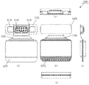
- FIG. 11 is an exploded view of the sensor device in the third embodiment;
- FIG. 11 is a schematic diagram of a cover member of a sensor device according to a third embodiment; (a) is a plan view of the cover member, (b) is a front view of the cover member, (c) is a bottom view of the cover member, and (d) is a side view of the cover member.
- FIG. 11 is an exploded view of a sensor device according to a fourth embodiment; It is a figure which shows the sensor apparatus in 5th Embodiment.
- (a) is a bottom view of the sensor device
- (b) is a plan view of the sensor device
- (c) is a front view of the sensor device
- (d) is a right side view of the sensor device
- (e) is a left side view of the sensor device. It is a diagram.
- FIG. 1 is a bottom view of the mounting portion
- FIG. 2 is a plan view of the mounting portion
- FIG. 3 is a front view of the mounting portion
- (d) is a right side view of the mounting portion
- (e) is a left side of the mounting portion.
- FIG. 14 is a diagram showing a unit substrate included in the main body of the sensor device according to the fifth embodiment; (a) is a bottom view of the unit board, (b) is a plan view of the unit board, (c) is a front view of the unit board, (d) is a right side view of the unit board, and (e) is a left side of the unit board. It is a plan view.
- FIG. 11 is a perspective view of a unit substrate included in a main body of a sensor device according to a fifth embodiment;
- FIG. 12 is an exploded view of another shape of the mounting portion of the sensor device in the fifth embodiment;
- wearable sensors installed in devices such as watches and clothing, and wearable sensors attached to the skin are used as a method of acquiring biological information such as the heart rate, respiratory rate, body temperature, SpO2, etc. of the subject.
- Wearable sensors attached to the skin have the advantage of being able to continuously acquire biological information 24 hours a day, but generally have the disadvantage of lacking flexibility in the main components such as the battery, control circuit, and sensor device. be. Therefore, in the case of such a wearable sensor lacking in flexibility, since it is difficult to bend and stretch, there is a problem that it is difficult to be attached to the skin, and the attachment site is limited.
- the target person is a person whose biological information is measured and whose body movement is detected, for example, a patient or a person being assisted.
- the subjects may include healthy people, regardless of age or gender.
- staff refers to persons other than the target person who uses the data acquired from the sensor.
- the staff refers to medical workers such as doctors and nurses, facility workers such as caregivers working at the facility, and includes home caregivers such as family members and visiting service staff.
- medical workers such as doctors and nurses
- facility workers such as caregivers working at the facility
- home caregivers such as family members and visiting service staff.
- training gyms and fitness clubs it means trainers and instructors.
- construction sites and event sites not only industrial physicians but also counselors, operational managers and the like are included.
- FIG. 1 is a diagram illustrating an overview of an entire system 1000 including a sensor device 1.
- the sensor device 1 is a device that can be directly attached to the subject's P body.
- the sensor device 1 can be attached directly to any part of the human body, such as the upper arm, chest, or thigh of the subject P, using an attachment member (for example, double-sided tape or the like).
- the sensor device 1 can be connected to, for example, a terminal device 9 by wireless communication.
- short-range wireless communication Bluetooth (registered trademark), BLE, ZigBee (registered trademark)
- wireless LAN such as WiFi
- a mobile communication network such as LTE/4G/5G may be used.
- the sensor device 1 and the terminal device 9 may be connected by any communication method.
- the terminal device 9 can acquire the biological information of the subject P from the sensor device 1 by executing the installed application.
- the sensor device 1 may transmit the biological information to a device in the immediate vicinity of the bed device or to a device used by staff or the like.
- the sensor device 1 may be directly connected to a server or the like and automatically store the biological information of the subject in the server.
- FIG. 2 is an exploded view of the sensor device 1.
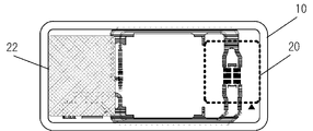
- FIG. 3A is a top view of the sensor device 1 including the cover.
- FIG. 3B is a top view of the sensor device 1 with the lid removed (excluding the lid).
- the sensor device 1 includes, as lower layers, a circuit board 10 that serves as a base and an attachment member (double-sided tape 50, single-sided tape 52) attached to the lower side of the circuit board 10.
- a circuit board 10 that serves as a base
- an attachment member double-sided tape 50, single-sided tape 52
- the sticking member may be included.
- the battery 22 is provided on the circuit board 10
- the battery 22 is included in the lower layer.
- the sensor device 1 also has a cover member 32 as an upper layer. Then, the circuit board 10 including the bonding member of the lower layer and the cover member 32 of the upper layer are combined to form the case portion 30 . That is, the case portion 30 does not include the control unit 20 .
- a plurality of units such as the control unit 20 and other sensor units can be connected to the circuit board 10 .
- the circuit board 10 is a stretchable circuit board.
- the circuit board 10 is made of an electronic material such as a metal paste for electrodes (for example, gold paste, silver paste, copper paste, etc.) as a conductive member on a sheet member (sheet portion) made of urethane. Print the wiring.
- the sheet member is made of a stretchable material such as urethane, and is characterized in that it does not give a sense of discomfort when applied to the user's skin.
- a battery 22 and a control unit 20 can be provided on the circuit board 10 . Further, as will be described later, the circuit board 10 can be provided with a sensor on the board, or can be additionally provided with a sensor unit.
- the sensor device 1 is provided with a battery 22 on one side. Further, the sensor device 1 is provided with the control unit 20 on the other side of the battery 22 and the sensor device 1 on the opposite side in the longitudinal direction. Further, the sensor device 1 is configured so that a sensor unit can be provided in the center.
- the circuit board 10 can be easily wired by arranging the sensor unit near the connector. Also, by shortening the distance between the sensor unit and the connector, it is possible to prevent noise from entering the wiring.
- the circuit board 10 is a bendable flexible circuit board. Therefore, the softness of the circuit board 10 as a whole becomes the softness of the sensor device 1 as a whole. Therefore, it is important to devise ways to avoid overlapping parts as much as possible. Also, even if the parts overlap, it is important to keep it to a minimum extent.
- a thin flexible battery is a battery formed of a thin sheet material.
- a separator film
- an electrolytic solution aqueous solution
- the battery 22 is configured integrally with the circuit board 10 .
- the control unit 20 is detachable
- the battery 22 may not be detachable and may have a so-called disposable configuration. In this manner, the circuit board 10 and the battery 22 are configured as lower layers and are replaceable after use.
- the battery 22 may be detachable from the circuit board 10 . In this case, the user or staff can replace the battery 22 .
- the control unit 20 has a control section for controlling the sensor device 1, a communication section for communication, and a storage section for storing various data and programs.
- the control unit 20 is provided with connection terminals, and can be connected to the sensor device 1 via the connection terminals.
- the control unit 20 may further have other configurations.
- the control unit 20 may have a processing section that processes data obtained from sensors.
- the processing unit may perform edge processing on the data acquired from the sensor, or calculate an index from the data acquired from the sensor.
- these functions may be mounted on one controller as SoC (System-On-a-Chip).
- control unit 20 is configured to be detachable from the circuit board 10 using connection terminals. For example, when the sensor device 1 is replaced, the subject, staff, or the like can remove only the control unit 20 . This makes it possible to replace only the case portion 30, which is a portion other than the control unit 20.
- FIG. 1 A block diagram illustrating an exemplary computing environment in accordance with the present disclosure.
- the case part 30 refers to a configuration other than the control unit 20.
- the case part 30 may be integrated with a separately mountable unit. That is, the case portion 30 is configured as a first member, and the control unit 20 is configured as a second member. The first member and the second member are configured to be detachable. Therefore, by removing the control unit 20, which is the second member, it is possible to replace only the case portion 30, which is the first member.
- control unit 20 can be reused even if the target person changes, which is economical. For example, in hospitals, facilities, etc., the control unit 20 can be used repeatedly even if patients or residents are replaced.
- the sensor device 1 can be kept clean and effective against infectious diseases by exchanging the case portion 30 for each subject.
- the sensor device 1 can be used by replacing the control unit 20 even if the case part 30 is replaced. As a result, if the control unit 20 stores the information of the subject himself/herself or the biological information or the like, the sensor device 1 can take over the data even if the case portion 30 is replaced. can.
- the sticking member has a double-sided tape 50 stuck to the lower side of the circuit board 10 and a single-sided tape 52 protecting one side of the double-sided tape 50 .
- the user can attach the sensor device 1 to the human body by peeling off the single-sided tape 52 and attaching the double-sided tape 50 to the skin.
- the double-sided tape 50 may be further provided with a protective member. That is, the sensor device 1 may further include a protective member for protecting the subject's skin between the subject and the double-sided tape.
- the protective member may use a gel adhesive or the like as a sticking member between the double-sided tape and the subject.
- the sensor device 1 has a lid portion 40 as a member forming the case portion 30 .
- the lid portion 40 is made of, for example, a mold material (mold resin).
- the lid portion 40 forms a flap (tongue-shaped body) 402 by leaving a part of the cover portion 40 in the vicinity of the central portion on the one end side and making a cut.
- the fulcrum of the flap 402 in the present embodiment is provided on the outer side of the lid portion 40 and is formed so that the inner side opens, but it may be formed vice versa.
- a fulcrum may be provided on the upper side or the lower side of the lid portion 40 so that the lower side or the upper side may be opened.
- the flap 402 By using the flap 402 on the lid part 40, the subject, staff, etc. can easily attach and detach the control unit 20. That is, it is preferable that the flap 402 is formed in a size that allows the control unit 20 to be attached and detached.
- a plurality of flaps 402 may be formed as necessary.
- a flap may be formed by making a cut at a position where the battery 22 can be replaced.
- the lid portion 40 may be cut so as to form a flap at the position of the control unit 20 to be added and the position of the unit to be added separately.
- the lid portion 40 may have a shape other than that of a flap, as long as it has a notch that allows easy attachment and detachment of the control unit 20 .
- the lid portion 40 may be further provided with a fitting type lid, or may be provided with a window portion.
- the lid portion 40 may be partially open.
- the sensor of the additional unit can be provided in an open area.
- a side wall 44 is provided between the circuit board 10 and the lid portion 40 .
- the side wall 44 forms a space between the circuit board 10 and the lid portion 40 to accommodate each unit, the battery 22 , and the like. Also, the side wall 44 is adhered to the circuit board 10 with double-sided tape 46 . Also, the side wall 44 is adhered to the lid portion 40 with double-sided tape 42 .
- the side walls 44 are also made of the same material as the lid portion 40 .
- the side wall 44 is also made of the molding material, so that the sensor device 1 can be easily bent or stretched.
- FIG. 4 is a diagram showing a printed wiring diagram of the sensor device 1.
- the connection terminal 120 (power supply terminal) of the battery 22 is arranged on the left side (battery 22 side) of FIG. That is, a negative connection terminal 122 of the battery 22 and a positive connection terminal 124 of the battery 22 are arranged.
- control unit 20 is arranged on the opposite side of the battery 22 .
- the control unit 20 is connected to the circuit board 10 via the connector section 110 .
- the connection terminal 120 of the battery 22 is connected to the connector section 110 by extending wiring along the vicinity of the end of the sensor device 1 (under the circuit board in FIG. 4) toward the other end. Accordingly, when connected to the connection terminal 120 , the battery 22 supplies power to the control unit 20 via the connector section 110 .
- the connector section 110 extends along the wiring along the vicinity of the end of the sensor device 1 toward the battery side and connects to the temperature sensor 140 . That is, the temperature sensor 140 connects to the control unit 20 .
- the control unit 20 can receive information about temperature (eg, body temperature of the subject wearing it) from a connected temperature sensor 140 .
- the connector section 110 may be easily disconnected from the control unit 20 (connection with the connector section 210) due to the tensile force caused by the expansion and contraction of the circuit board 10. Therefore, the connector section 110 may utilize flexible printed circuits (FPC).
- FPC flexible printed circuits
- the wiring is routed along the upper and lower edges of the sensor device 1 when connecting from the connection terminal 120 of the battery 22 to the connector section 110 and when connecting from the connector section 110 to the temperature sensor 140 .
- the sensor device 1 can form a space in which the sensor unit 24 is provided in the center.
- the sensor provided on the circuit board 10 is the temperature sensor 140 in this embodiment, it may be another sensor.
- the sensor provided on the circuit board 10 may be a sensor capable of acquiring biological information, such as a heart rate sensor or an SPO2 sensor.
- the circuit board 10 does not have to be provided with a sensor.
- the control unit 20 receives information on a sensor unit that will be provided later, as will be described later.
- the lower layer circuit board 10 may be appropriately provided with one or more holes. By providing the hole portion, the circuit board 10 can reduce the contact area with the skin, and can contribute to the reduction of stuffiness when worn.
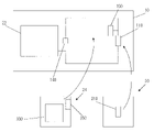
- FIG. 5A is a schematic diagram of the circuit board 10 and between units.
- the circuit board 10 and the control unit 20 are electrically connected.
- the connector portion 150 of the circuit board 10 and the connector portion 350 of the sensor unit 24 are electrically connected.
- the sensor device 1 including the units becomes an integrated device.
- the position of the connector section 150 is preferably near the connector section 110 .
- the connector section 150 may be directly connected to a part of the connector section 110 .
- the connector section 150 may be shared with the connector section 110 .
- a battery 22 and a temperature sensor 140 are provided on the circuit board 10 . That is, since the circuit board 10 is directly attached to the subject, it may be replaced as appropriate. In this case, the subject, staff, or the like need only replace the circuit board 10 (battery 22, temperature sensor 140) by removing the unit at the time of replacement. Also, the control unit 20 and the sensor unit 24 can be reconnected to another circuit board 10 as necessary. That is, the control unit 20 and the sensor unit 24 can be reused.
- FIG. 5B schematically shows the control unit 20.
- the control unit 20 includes a control section 200 , a connector section 210 , a storage section 220 and a communication section 230 on a circuit board 290 .
- the control unit 200 has a function of controlling the sensor device 1 .
- the control unit 200 is, for example, a controller that integrates an arithmetic device, a control device, and a storage device.
- the control unit 200 is generally implemented by a CPU (Central Processing Unit), SoC (System-on-a-chip), or the like.
- the storage unit 220 stores various programs and various data necessary for the operation of the sensor device 1 .
- the storage unit 220 is a general semiconductor memory.
- the storage unit 220 includes a rewritable memory (RAM: Random Access Memory) as a main storage device used by the control unit 200 when executing processing, and a non-volatile memory (ROM: Read Only Memory). Also, the storage unit 220 may be a storage that stores programs, data, and the like.
- the communication unit 230 communicates with external devices. For example, it has a function of wireless communication, and can communicate with the terminal device 9 by Bluetooth (registered trademark), which is short-range wireless communication. In addition, as long as it can provide a function of communicating with an external device, for example, it may be a module that can be connected to a network such as a wireless LAN, or a communication module that performs communication by LTE/4G/5G. . If the communication unit 230 can be connected to 5G or the like, the biometric information may be transmitted directly to the server device.
- the connector part 210 is a connector that connects with the connector part 110 of the circuit board 10 .
- the circuit board 10 and the control unit 20 can communicate with each other by electrically connecting the connector section 210 and the connector section 110 (for example, by fitting them together to form a wire connection and electrically connect them). This allows power to be supplied from the battery 22 and the components in the control unit 20 to operate. Further, the control unit 20 can receive sensor information including biological information from the sensors mounted on the circuit board 10 and the sensor unit 24 .
- the circuit board 290 of the control unit 20 is composed of a bendable board.
- the circuit board 290 has a bending member 295 that can be flexibly bent in the center.
- the control unit 20 is provided with the connector section 210 on one side through the bending member 295, and the control section 200 and the like on the other side.
- the bending member 295 may use, for example, a flexible printed circuit board (FPC: Flexible printed circuits).
- FIG. 6 is a diagram schematically showing the case where the sensor device 1 is attached to the subject P.
- FIG. A battery 22 is provided on the circuit board 10 .
- a connector portion 210 of the control unit 20 is connected to the connector portion 110 .
- control unit 20 the entire circuit board 290 is folded in two by bending the bending member 295 in a mountain fold.
- the control unit 20 is connected to the circuit board 10 by bending the connector portion 210 , the control portion 200 , the storage portion 220 and the communication portion 230 outward.
- the sensor device 1 is integrated by covering it with the lid portion 40 .
- the sensor device 1 is attached to the subject P using a double-sided tape 50 attached to the lower side of the circuit board 10 . Thereby, the biometric information of the subject P can be acquired.
- control unit 20 may be provided with a sensor.
- control unit 20 may be provided with an acceleration sensor.
- the sensor device 1 can acquire the subject's body motion, respiration, and heartbeat using only the control unit 20 .
- control unit 20 has been described using the bendable circuit board 290 as an example, the circuit board 290 may have other configurations.
- the circuit board 290 may constitute the control unit 20 using a double-sided board or a multilayer board.
- the sensor unit 24 is a sensor that can be added by the subject, staff, or the like.
- the sensor unit 24 has a connector section 350 .
- the connector portion 350 is electrically connected to the circuit board 10 by connecting to the connector portion 150 of the circuit board 10 .
- the sensor unit 24 has a sensor 300 as schematically shown in FIG. 5A.
- the sensor 300 may be any sensor such as, for example, a photosensor, a sound sensor, or a vibration sensor.
- the sensor 300 can acquire heartbeat, blood flow, and SpO2 by using an image sensor.
- the image sensor of sensor 300 may have a lower resolution than a general image sensor. By lowering the resolution of the image sensor of the sensor 300, a smaller sensor can be used.
- the sensor unit 24 is preferably composed of a flexible sensor unit.
- the sensor unit 24 becomes a sensor device that easily follows the skin as a whole.
- control unit 20, sensor unit 24 may be in the state of a substrate, or the substrate may be packaged with any member.
- the sensor unit 24 is included in the above-described second member (the member including the control unit 20). That is, it is configured to be detachable from the circuit board 10 which is the first member.
- the sensor unit 24 can also be configured to be included in the first member.
- the sensor unit 24 may be configured integrally with the circuit board 10 . Since the circuit board 10 and the sensor unit 24 are integrally configured, the case portion 30 may be separated for each type of the sensor unit 24 . In this case, when attaching the sensor device 1 to the subject, the staff may select the case portion 30 corresponding to the required sensor and connect the control unit 20 to the sensor device 1 .
- the control unit 20 and the sensor unit 24 of the sensor device 1 can be removed from the circuit board 10 . Therefore, only the case portion 30 (the first member including the circuit board 10 and the like) that touches the skin should be replaced, and the control unit 20 and the added sensor unit 24 portion of the second member should be continuously and repeatedly used. can be done.
- the circuit board 10 that constitutes the case portion 30 may not have a sensor.
- the subject, staff, or the like can freely add the necessary sensor units 24 .
- the control program and the optimized processing algorithm can be reused even if the case part 30 is changed.
- the sensor body and the battery can be made flexible and mounted on the case portion 30 .
- the only hard part is the control unit 20 (processing circuit) that is miniaturized to the minimum required size, and the case part 30 realizes a bandage-type flexible sensor structure. As a result, it is easy to adapt to the subject's skin, and there is an effect of high wearability that does not cause discomfort.
- control unit 20 and the case part 30 are made detachable so that the case part 30 can be disposed of each time and the control unit 20 can be used repeatedly.
- the cost can be reduced by repeatedly using the expensive control unit 20 (processing circuit).
- the optimized parameters and data processing algorithm can be used continuously while the sensor of the case part 30 can be changed depending on the application.
- the second embodiment differs from the first embodiment in the shape of the sensor.
- FIG. 7 is an exploded view of the sensor device 2000 according to the second embodiment.
- FIG. 8 is a diagram showing the sensor device 2000. As shown in FIG. 8(a) is a plan view seen from above, FIG. 8(b) is a side view seen from the side, and FIG. 8(c) is a front view seen from the front.
- FIG. 8(d) is a diagram showing the state of the circuit board viewed from the side, and FIG. 8(e) is a diagram showing the state of the circuit board viewed from the front.
- FIG. 9 is a diagram showing only the lid portion 2040. As shown in FIG. 9(a) is a plan view of the lid 2040 viewed from above, FIG. 9(b) is a side view of the lid 2040, and FIG. 9(c) is a front view of the lid 2040.
- FIG. 9 is a diagram showing only the lid portion 2040. As shown in FIG. 9(a) is a plan view of the lid 2040 viewed from above, FIG. 9
- the sensor device 2000 includes, as lower layers, a circuit board 2010 and an attachment member attached to the lower side of the circuit board 2010 .
- the circuit board 2010 is a stretchable board and a circuit board having elasticity.
- the circuit board 2010 is a circuit board in which a wiring pattern (circuit pattern) is printed on a PCB (polychlorinated phenyl) substrate using a conductive member.
- circuit board 2010 may be equipped with a battery. Also, the circuit board 2010 may have a sensor that acquires the subject's biological information. For example, circuit board 2010 is preferably provided with a temperature sensor.
- the sticking member has a double-sided tape 2050 stuck to the lower side of the circuit board 2010 , a protective member 2052 and a separator 2054 .
- the protective member 2052 is a member for protecting the skin, and a gel adhesive or the like may be used.
- the circuit board 2010 does not have to be provided with the protective member 2052 as an attachment member. In this case, the circuit board 2010 may be attached directly to the subject with double-sided tape 2050 .
- the sensor device 2000 has a lid portion 2040 .
- the lid portion 2040 is made of, for example, a molding material.
- lid portion 2040 it is preferable to provide a space between the lid portion 2040 and the circuit board 2010 so that members such as a battery and a control unit arranged on the circuit board 2010 can be accommodated. Therefore, side wall 2020 is provided between lid portion 2040 and circuit board 2010 . Sidewalls 2020 are formed with rectangular cutouts to provide space for components overlying circuit board 2010 to be accommodated. Then, the circuit board 2010 and the side wall 2020 are adhered with a double-sided tape 2022 . Moreover, the double-sided tape 2042 adheres the side wall 2020 and the lid portion 2040 together. Also, the lid portion 2040 may be provided with an insulator 2030 in order to protect the members of the circuit board 2010 .
- the circuit board 2010 has the battery 22B, the control unit 200B, and the like arranged thereon.
- the sensor device 2000 of the present embodiment includes a rectangular region R1 provided with a circuit board 2010 and a region R2 provided with a temperature sensor 140 .
- a region R2 in which the temperature sensor 140 is provided is a region protruding from the region R1.
- the sensor device 2000 of the present embodiment only the area R2 can be arranged and attached to the user's armpits, and the area R1 can be arranged and attached to the user's chest or back. As a result, it is possible to reduce the area of the sensors arranged under the user's armpits, thereby reducing the user's sense of discomfort.
- the sensor of the third embodiment consists of a circuit board and a packaging member.
- FIG. 10 is an exploded view of the sensor device 3000 according to the third embodiment.
- the sensor device 3000 includes a circuit board 3100 as a first member and a packaging member 3200 as a second member.
- the difference from the first embodiment is that the portion of the case portion 30 of the replaceable first member is the portion of the circuit board 3100 .
- the control unit 20, which is a second member that can be used, is integrally formed as a packaging member 3200. As shown in FIG.
- the packaging member 3200 has a cover member 3210 , a control unit 3220 and a lid portion 3230 .
- the cover member 3210 and the lid portion 3230 are made of silicon, for example.
- the detailed shape of the cover member 3210 is as shown in FIG. FIG. 11(a) is a plan view of the cover member 3210.
- FIG. 11(b) is a front view of the cover member 3210.
- FIG. 11(c) is a bottom view of the cover member 3210.
- FIG. 11D is a side view (right side view) of the cover member.
- the cover member 3210 has a predetermined height (thickness) so that the side on which the control unit 3220 is arranged (R side in FIG. 11(a)) forms a space inside. That is, when the circuit board 3100 is used as a base, the height is such that the control unit 3220 can be accommodated.
- center of the cover member 3210 also has a predetermined height (thickness) so as to form a space inside so that an additional unit (sensor unit) can be arranged.
- a battery is arranged on the side opposite to the side where the control unit 3220 is arranged (the L side in FIG. 11(a)).
- the cover member 3210 has a height (thickness) of a space where the battery can be placed on the battery side.
- the sensor device 3000 uses a thin flexible battery. Therefore, the height (thickness) of cover member 3210 on the battery side does not have to be as high (thickness) as that of the control unit or the sensor unit.
- the cover member 3210 shown in FIG. 11 has a lower height on the battery side on the L side and a higher height on the control unit 3220 side on the R side. Also, the cover member 3210 has a shape that gradually increases in height (increases in thickness) from the L side to the vicinity of the center.
- the cover member 3210 may have a plurality of holes on the battery side. By having a plurality of holes in the cover member 3210, it is possible to cope with heat generation of the battery.
- the packaging member 3200 may arrange the control unit 3220 in the space of the cover member 3210, and attach the lid portion 3230, which is a lid member, to the cover member 3210 so as to cover the opening.
- the packaging member 3200 is configured such that the cover member 3210, the control unit 3220, and the lid portion 3230 are integrated as one package.
- the circuit board 3100 side of the lid portion 3230 can be attached with an adhesive member.
- the lid portion 3230 is configured such that a double-sided tape is provided on the lower side of the lid portion 3230 so that the lid portion 3230 can be attached to the circuit board 3100 . Since the lid portion 3230 and the circuit board 3100 are attached with double-sided tape, they are detachable.
- An adhesive member is also provided on the lower side of the circuit board 3100 (on the side opposite to the packaging member 3200).
- double-sided tape is attached to the lower side of the circuit board 3100 .
- the circuit board 3100 can be attached to a site such as the subject's skin using a double-sided tape.
- circuit board 3100 can be peeled off from the packaging member 3200 . This allows the circuit board 3100 to be replaced. Also, the packaging member 3200 containing the control unit 3220 can be used repeatedly.
- the circuit board 3100 is a stretchable board and a circuit board having elasticity.
- the circuit board 3100 is a circuit board in which a wiring pattern is printed on a PCB (polychlorinated phenyl) substrate using a conductive member.
- a battery may be mounted on this circuit board 3100 .
- the circuit board 3100 may have a sensor for acquiring the biological information of the subject.
- the packaging member 3200 including the second member, the control unit 3220 can be used repeatedly. Also, the circuit board 3100, which is the first member, can be replaced as needed.
- the fourth embodiment is an embodiment in which the cover portion 3230 is removed from the configuration of the third embodiment.
- a sensor device 4000 of this embodiment is shown in FIG.
- a control unit 3220 is connected to a circuit board 3100 by a subject or staff. After the control unit 3220 is connected to the circuit board 3100, the entire circuit board 3100 is covered with the cover member 3210 to configure the sensor device 4000.
- FIG. 1 A sensor device 4000 of this embodiment is shown in FIG.
- a control unit 3220 is connected to a circuit board 3100 by a subject or staff. After the control unit 3220 is connected to the circuit board 3100, the entire circuit board 3100 is covered with the cover member 3210 to configure the sensor device 4000.
- the cover member 3210 and the circuit board 3100 are adhered with an adhesive member such as double-sided tape. Also, at this time, the control unit 3220 is accommodated in the space formed in the cover member 3210 .
- the present embodiment enables the sensor device 4000 to be realized with a simpler configuration than the third embodiment.
- the fifth embodiment describes a sensor device 5000 shown in the form shown in Figures 13-20.
- FIG. 13 and 14 are diagrams showing the appearance of the sensor device 5000.
- FIG. 13(a) is a bottom view of the sensor device 5000
- FIG. 13(b) is a plan view of the sensor device 5000
- FIG. 13(c) is a front view of the sensor device 5000.
- 13(d) is a right side view of the sensor device 5000 viewed from the right side
- FIG. 13(e) is a left side view of the sensor device 5000 viewed from the left.
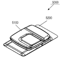
- FIG. 14 is a perspective view of the sensor device 5000 as viewed obliquely from above.
- the sensor device 5000 includes a body portion 5100 and an attachment portion 5200 for attaching the sensor device 5000 to the human body.
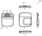
- FIG. 15 and 16 are diagrams showing the appearance of the main body 5100.
- FIG. 15(a) is a bottom view of the main body 5100 viewed from the bottom
- FIG. 15(b) is a plan view of the main body 5100 viewed from above
- FIG. 15(c) is a front view of the main body 5100 viewed from the front
- 15(d) is a right side view of the main body 5100 as seen from the right side
- FIG. 15(e) is a left side view of the main body 5100 as seen from the left.
- FIG. 16 is a perspective view of the main body 5100 viewed obliquely from above.
- FIG. 17 and 18 are diagrams showing the appearance of the mounting portion 5200.
- FIG. 17(a) is a bottom view of the mounting portion 5200 viewed from the bottom
- FIG. 17(b) is a plan view of the mounting portion 5200 viewed from the top
- FIG. 17(c) is a front view of the mounting portion 5200.
- 17(d) is a right side view of the mounting portion 5200 viewed from the right side
- FIG. 17(e) is a left side view of the mounting portion 5200 viewed from the left.
- FIG. 18 is a perspective view of the mounting portion 5200 as viewed obliquely from above.
- FIG. 19 and 20 are diagrams showing the appearance of a unit substrate 5300 built into the main body 5100.
- FIG. 19(a) is a bottom view of the unit substrate 5300
- FIG. 19(b) is a plan view of the unit substrate 5300
- FIG. 19(c) is a front view of the unit substrate 5300.
- 19(d) is a right side view of the unit board 5300 viewed from the right side
- FIG. 19(e) is a left side view of the unit board 5300 viewed from the left.
- FIG. 20 is a perspective view of the unit board 5300 as viewed obliquely from above.
- the main unit 5100 includes, for example, a control unit.
- the control unit may mount components capable of realizing various functions on the unit board 5300 shown in FIGS.
- the parts mounted on the unit board 5300 may be parts made of semiconductors, such as CPU (Central Processing Unit), DSP (Digital Signal Processor), MCU (Micro Controller Unit), FPGA (Field Programmable Gate Array). ), SoC (System on a Chip), or the like.
- CPU Central Processing Unit
- DSP Digital Signal Processor
- MCU Micro Controller Unit
- FPGA Field Programmable Gate Array
- SoC System on a Chip
- the unit board 5300 has a circuit board 5310 and a reinforcing member 5320 connected by a flexible board 5330 .
- the flexible substrate 5330 is a bendable circuit substrate (eg, flexible printed wiring board). Therefore, the sensor device 5000 as a whole is configured to be bendable.
- the flexible substrate 5330 may be formed in a substantially V shape. That is, the flexible board 5330 may be formed in a curved or linear shape so that the circuit board 5310 side is wider and the reinforcing member 5320 side is narrower.
- the flexible substrate 5330 has the shape shown in FIG. 19, for example, so that even if a force is applied to twist the reinforcing member 5320 and the circuit board 5310, stress concentration is applied to the mounted components mounted on the circuit board 5310. This prevents cracks, poor contact, and damage to parts.
- the unit substrate 5300 may be configured entirely by a flexible substrate.
- a reinforcing plate may be provided or resin potting may be performed.
- the circuit board 5310 is mounted with the various components described above.
- the circuit board 5310 may mount an acceleration sensor or a communication unit 5340 in addition to a controller such as a CPU.
- the communication unit 5340 is a module that implements wireless communication.
- the communication unit 5340 may realize wireless communication such as WiFi, mobile communication such as 4G/5G, or short-range wireless communication such as Bluetooth or NFC, for example.
- the circuit board 5310 may further mount a sensor unit.
- the sensor unit may be equipped with, for example, an acceleration sensor, an inclination sensor, a gyro sensor, or the like.
- the circuit board 5310 in FIG. 19 is equipped with an acceleration sensor for acquiring the movement (body movement) of the subject, the behavior of the subject, and the biometric information of the subject.
- the reinforcing member 5320 is equipped with mounting terminals that connect to the mounting portion 5200 .
- the reinforcing member 5320 has connection terminals 5120 .
- the connection terminal 5120 is connected to the connection terminal 5240 of the attachment portion 5200 .
- the mounting portion 5200 and the main body portion 5100 are electrically connected to function as the sensor device 5000 .
- the reinforcing member 5320 may further have a circuit board.
- the circuit board and the reinforcing member 5320 may be fixed with an adhesive or double-sided tape.
- the reinforcing member 5320 is, for example, a plate-like member (reinforcing plate), and may be made of stainless steel, plastic, aluminum, or the like.
- the reinforcing member 5320 may have a connecting member 5130 .
- the connection member 5130 is composed of, for example, a magnet (for example, a magnet, a ferromagnetic material, or the like).
- the connection member 5130 and the connection member 5230 of the mounting portion are magnetically adhered, so that the body portion 5100 and the mounting portion 5200 are connected so as not to come off.
- the connecting member 5130 and the connecting member 5230 facilitate positioning. Further, by providing the reinforcing member 5320, the contact stability of the connecting member 5230 can be ensured.
- FIGS. 15 and 16 the circuit board 5310, the reinforcing member 5320, and the flexible board 5330 are covered with the case member 5110 to constitute the main body 5100.
- FIG. 15 the circuit board 5310, the reinforcing member 5320, and the flexible board 5330 are covered with the case member 5110 to constitute the main body 5100.
- the attachment portion 5200 has a seat portion 5210 and an attachment body portion 5220 .
- the mounting main body 5220 may be equipped with a battery.
- the battery is housed in a housing portion 5225 within the mounting body portion 5220 .
- the battery supplies power to main body 5100 when connection terminal 5240 and connection terminal 5120 are connected.
- the mounting portion 5200 may have a medical tape for sticking to the skin on the lower layer (bottom layer) and a decorative sheet on the upper layer.
- a urethane sheet substrate or a flexible substrate may be provided as an intermediate layer between the lower layer and the upper layer.
- a sensor such as a temperature sensor may be further provided on the intermediate layer such as the urethane substrate.
- the decorative sheet in the upper layer may be made of, for example, a printable material. By printing characters, logos, etc. on the decorative sheet, it is possible to expand the range of design.
- the lower layer may be the seat portion 5210 and the upper layer may be the member covering the attachment body portion 5220.
- FIG. 17 the lower layer may be the seat portion 5210 and the upper layer may be the member covering the attachment body portion 5220.
- the mounting portion 5200 may be configured as shown in FIG.
- the attachment portion 5202 in FIG. 20 has a skin attachment tape 5212 as a lower layer and a decorative sheet 5222 as an upper layer.
- an intermediate layer between the upper layer and the lower layer has a urethane sheet 5250 .
- Urethane sheet 5250 is provided with flexible substrate 5260 , temperature sensor 5270 and battery 5280 .
- the flexible substrate 5260 is connected to the temperature sensor 5270 and the battery 5280 via wiring, for example.
- the flexible substrate 5260, the temperature sensor 5270, and the battery 5280 are arranged adjacent to each other in FIG.
- temperature sensor 5270 or battery 5280 may be connected to flexible substrate 5260 with silver paste wiring on urethane sheet 5250 .
- the flexible substrate 5260 is provided with connection portions (connection members 5230 and connection terminals 5240 ) for connection with the body portion 5100 .
- the flexible substrate 5260 has a connection terminal (power supply terminal), and the battery 5280 is connected through the connection terminal.
- the mounting portion 5200 may be provided with a sensor separately from the main body portion 5100.
- the mounting section 5200 can acquire the subject's body temperature by providing a temperature sensor.
- the attachment section 5200 can acquire the subject's heartbeat, SpO2, and the like by providing an optical sensor.
- the attachment part 5200 may measure electrocardiogram and myoelectricity by providing electrodes (for example, nanomesh electrodes, nanosheet electrodes, etc.) made of a flexible material.
- the body section 5100 can acquire information from the sensor provided on the mounting section 5200 . Thereby, the body part 5100 acquires information about the subject from the sensor provided in the body part 5100 and the sensor provided in the mounting part 5200 .
- the sheet portion 5210 is provided with an adhesive member on the surface that contacts the user.
- the sheet portion 5210 may have a double-sided tape attached to the surface shown in FIG. 17A (the surface in contact with the subject).
- the sheet portion 5210 may be attached to a location where the subject's biological information can be easily obtained.
- the sheet portion 5210 may be attached near the upper center of the chest. That is, by directly attaching the sensor device 5000 to the upper center of the chest of the subject, various biological information such as body temperature, heartbeat, respiration, and amount of activity of the subject can be obtained appropriately.
- the main body 5100 is preferably small, thin, and lightweight.
- the body portion 5100 may have a size of approximately 35 mm ⁇ 40 mm and a thickness of approximately 6 mm.
- the main body part 5100 may have a two-tone color scheme so that it can be perceived as thin.
- the packaging of the main body part 5100 may have a depression (recess) in the upper part.
- the body portion 5100 forms a concave portion 5115 on the upper side of the body portion 5100, as shown in FIG.
- the recessed portion 5115 is formed so as to have recesses on the upper surface and the lower surface over the entire width.
- This concave portion 5115 corresponds to a position where a flexible substrate 5330 having flexibility is present.
- the concave portion 5115 may be made of a flexible material. By doing so, the body portion 5100 can be bent around the concave portion 5115 . Therefore, the body part 5100 can be freely deformed along with the movement (body movement) of the subject.
- the sensor device 5000 of the present embodiment is lightweight and compact, so that the user can wear it comfortably.
- the sensor device 5000 can be easily deformed according to the movement of the body of the subject, and can be worn comfortably.
- the mounting portion 5200 is replaceable, a different mounting portion 5200 can be used for each subject. Since the attachment part 5200 has a disposable configuration (a configuration that can be discarded), the subject can use the sensor device 5000 in a clean state by using the new attachment part 5200 .
- sensor device 10 circuit board 20 control unit 22 battery 24 sensor unit 40 lid 42 double-sided tape 44 side wall 46 double-sided tape 50 double-sided tape 52 single-sided tape 9 terminal device
Landscapes
- Engineering & Computer Science (AREA)
- Microelectronics & Electronic Packaging (AREA)
- Measuring Pulse, Heart Rate, Blood Pressure Or Blood Flow (AREA)
Priority Applications (1)
| Application Number | Priority Date | Filing Date | Title |
|---|---|---|---|
| JP2023529575A JPWO2022264591A1 (https=) | 2021-06-18 | 2022-03-22 |
Applications Claiming Priority (2)
| Application Number | Priority Date | Filing Date | Title |
|---|---|---|---|
| JP2021101708 | 2021-06-18 | ||
| JP2021-101708 | 2021-06-18 |
Publications (1)
| Publication Number | Publication Date |
|---|---|
| WO2022264591A1 true WO2022264591A1 (ja) | 2022-12-22 |
Family
ID=84527049
Family Applications (1)
| Application Number | Title | Priority Date | Filing Date |
|---|---|---|---|
| PCT/JP2022/013138 Ceased WO2022264591A1 (ja) | 2021-06-18 | 2022-03-22 | センサ装置 |
Country Status (2)
| Country | Link |
|---|---|
| JP (1) | JPWO2022264591A1 (https=) |
| WO (1) | WO2022264591A1 (https=) |
Citations (2)
| Publication number | Priority date | Publication date | Assignee | Title |
|---|---|---|---|---|
| JP2021034394A (ja) * | 2019-08-13 | 2021-03-01 | 株式会社イノアックコーポレーション | 基板ケース |
| JP2021044438A (ja) * | 2019-09-12 | 2021-03-18 | 大日本印刷株式会社 | 伸縮性デバイス |
-
2022
- 2022-03-22 JP JP2023529575A patent/JPWO2022264591A1/ja active Pending
- 2022-03-22 WO PCT/JP2022/013138 patent/WO2022264591A1/ja not_active Ceased
Patent Citations (2)
| Publication number | Priority date | Publication date | Assignee | Title |
|---|---|---|---|---|
| JP2021034394A (ja) * | 2019-08-13 | 2021-03-01 | 株式会社イノアックコーポレーション | 基板ケース |
| JP2021044438A (ja) * | 2019-09-12 | 2021-03-18 | 大日本印刷株式会社 | 伸縮性デバイス |
Also Published As
| Publication number | Publication date |
|---|---|
| JPWO2022264591A1 (https=) | 2022-12-22 |
Similar Documents
| Publication | Publication Date | Title |
|---|---|---|
| US12245859B2 (en) | Physiological monitoring device | |
| CN102740766B (zh) | 用于生理监测的具有电子设备的身体粘附贴片 | |
| US10939870B2 (en) | Patient worn sensor assembly | |
| US8773258B2 (en) | Data collection module for a physiological data collection system | |
| WO2007071180A1 (en) | Wearable, wireless and distributed physiological signal monitoring system | |
| ITVI20110027A1 (it) | Dispositivo multisensoriale per il monitoraggio di parametri biologici e vitali nonche' sistema di sorveglianza remota incorporante tale dispositivo | |
| US20260114807A1 (en) | Self contained monitor and system for use | |
| KR102541687B1 (ko) | 신생아용 맥박계 | |
| WO2022264591A1 (ja) | センサ装置 | |
| HK1176847A (en) | Body adherent patch with electronics for physiologic monitoring |
Legal Events
| Date | Code | Title | Description |
|---|---|---|---|
| 121 | Ep: the epo has been informed by wipo that ep was designated in this application |
Ref document number: 22824587 Country of ref document: EP Kind code of ref document: A1 |
|
| WWE | Wipo information: entry into national phase |
Ref document number: 2023529575 Country of ref document: JP |
|
| NENP | Non-entry into the national phase |
Ref country code: DE |
|
| 122 | Ep: pct application non-entry in european phase |
Ref document number: 22824587 Country of ref document: EP Kind code of ref document: A1 |