WO2022264403A1 - 制御システム、制御方法、コントローラ、及びプログラム - Google Patents
制御システム、制御方法、コントローラ、及びプログラム Download PDFInfo
- Publication number
- WO2022264403A1 WO2022264403A1 PCT/JP2021/023197 JP2021023197W WO2022264403A1 WO 2022264403 A1 WO2022264403 A1 WO 2022264403A1 JP 2021023197 W JP2021023197 W JP 2021023197W WO 2022264403 A1 WO2022264403 A1 WO 2022264403A1
- Authority
- WO
- WIPO (PCT)
- Prior art keywords
- terminal
- controller
- wireless network
- access point
- connection
- Prior art date
- Legal status (The legal status is an assumption and is not a legal conclusion. Google has not performed a legal analysis and makes no representation as to the accuracy of the status listed.)
- Ceased
Links
Images





Classifications
-
- H—ELECTRICITY
- H04—ELECTRIC COMMUNICATION TECHNIQUE
- H04W—WIRELESS COMMUNICATION NETWORKS
- H04W28/00—Network traffic management; Network resource management
- H04W28/02—Traffic management, e.g. flow control or congestion control
- H04W28/10—Flow control between communication endpoints
- H04W28/14—Flow control between communication endpoints using intermediate storage
-
- H—ELECTRICITY
- H04—ELECTRIC COMMUNICATION TECHNIQUE
- H04W—WIRELESS COMMUNICATION NETWORKS
- H04W72/00—Local resource management
- H04W72/04—Wireless resource allocation
-
- H—ELECTRICITY
- H04—ELECTRIC COMMUNICATION TECHNIQUE
- H04W—WIRELESS COMMUNICATION NETWORKS
- H04W84/00—Network topologies
- H04W84/02—Hierarchically pre-organised networks, e.g. paging networks, cellular networks, WLAN [Wireless Local Area Network] or WLL [Wireless Local Loop]
- H04W84/10—Small scale networks; Flat hierarchical networks
- H04W84/12—WLAN [Wireless Local Area Networks]
Definitions
- the present disclosure relates to a control system, control method, controller, and program for allocating communication bands in an access network.
- the end-end of the network can be divided into wireless and wired sections.
- a priority control function called IEEE802.11 Enhanced Distributed Channel Access (EDCA) as an existing technology.
- EDCA Enhanced Distributed Channel Access
- EDCA is controlled on a terminal (destination) basis, and it is difficult to control on a traffic flow basis, such as enabling quality control on a service and application basis. Therefore, techniques have been proposed to realize quality control for each service and application. (For example, see Non-Patent Document 3.)
- IEEE 802.11e-2005 IEEE Standard for Information technology--Local and metropolitan area networks--Specific requirements--Part 11: Wireless LAN Medium Access Control (MAC) and Physical Layer (PHY) Specifications - Amendment 8: Medium Access Control (MAC) Quality of Service Enhancements Wireless LAN standard IEEE802.11e that realizes QoS" Journal of the Institute of Image Information and Television Engineers Vol. 57, No. 11 Yuki Sakagami, Kazuki Ainoura, Tatsuya Fukui, et al.: "Proposal of quality control technology based on centralized control that does not depend on wireless network", The Institute of Electronics, Information and Communication Engineers General Conference March 9, 2021 B-6-5
- Non-Patent Document 3 it is necessary to record the connected terminal and access point in advance in the database unit, but in the actual terminal in the wireless network, connection/disconnection is repeated as people move. Therefore, it is difficult to record all terminals and access points in the controller in advance.
- the purpose of the present disclosure is to enable band allocation for each traffic flow even in a real wireless network where terminals repeatedly connect/disconnect as people move.
- a control system includes: A control system for controlling traffic in a wireless network, comprising: a terminal and an access point that mutually transmit packets over the wireless network; a controller that performs transmission control on the terminal and the access point; and The terminal holds in advance the node number of its own device and the information of the flow unit buffer, The controller is Before the access point establishes a connection with the terminal, establish a connection with the terminal using a connection sequence according to a protocol available in the wireless network; obtaining from the terminal the node number of the terminal and information of the per-flow buffer through the wireless network; After the access point establishes a connection with the terminal, for each traffic flow accumulated in the flow unit buffer of the terminal using the node number of the terminal and flow unit buffer information acquired through the wireless network, Control transmission.
- a control method includes: A control method for controlling traffic in a wireless network, comprising: The control method is transmission control performed by a controller for terminals and access points that mutually transmit packets via the wireless network, Before the access point establishes a connection with the terminal, the controller establishing a connection with the terminal using a connection sequence according to a protocol available in the wireless network; Obtaining from the terminal, through the wireless network, the node number of the own device and the information of the flow unit buffer previously held by the terminal, and After the access point establishes a connection with the terminal, The controller performs transmission control for each traffic flow accumulated in the flow unit buffer of the terminal using the node number of the terminal and the information of the flow unit buffer obtained through the wireless network.
- a controller includes: A controller for controlling traffic in a wireless network,
- the controller is a device that performs transmission control for terminals and access points that mutually transmit packets via the wireless network, Before the access point establishes a connection with the terminal, establishing a connection with the terminal using a connection sequence according to a protocol available in the wireless network; Obtaining from the terminal, through the wireless network, the node number of the own device and the information of the flow unit buffer previously held by the terminal, and After the access point establishes a connection with the terminal, The controller performs transmission control for each traffic flow accumulated in the flow unit buffer of the terminal using the node number of the terminal and the information of the flow unit buffer obtained through the wireless network.
- the program of the present disclosure is a program for realizing a computer as each functional unit provided in the apparatus according to the present disclosure, and is a program for causing the computer to execute each step included in the method executed by the apparatus according to the present disclosure. .
- FIG. 1 shows an example of a system configuration of the present disclosure; A configuration example of an access point is shown.
- FIG. 2 is a diagram explaining a database provided in an access point;
- FIG. 4 shows a configuration example of a controller. It is a figure explaining the database with which a controller is provided.
- 1 shows a configuration example of a terminal; It is a figure explaining the database with which a terminal is provided.
- FIG. 11 shows a flowchart when a terminal newly connects;
- FIG. FIG. 11 shows a flowchart when a terminal newly connects;
- FIG. FIG. 10 is a sequence diagram in a conventional communication system without a controller;
- FIG. 1 shows an example of the system configuration of the present disclosure.
- each terminal 11 is connected to an access point 12 through a wireless network 15 .
- the control system of the present disclosure comprises a controller 13 that controls this communication network.
- Controller 13 is connected to access point 12 through a dedicated control network.
- the controller 13 is connected to each terminal 11 by a connection sequence according to a protocol available on the wireless network 15 .
- FIG. 2 shows a configuration example of the access point 12.
- the access point 12 includes a database section 21 , a control signal transmission/reception section 22 and a scheduler section 23 .
- the access point 12 can also be realized by a computer and a program, and the program can be recorded on a recording medium or provided through a network.
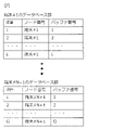
- FIG. 3 shows an example of information stored in the database unit 21.
- the database unit 21 sorts out the information in the flow unit buffers FB2#1 to FB2#K of its own device.
- the access point 12 records its own buffer number in its own database section 21 .
- FIG. 4 shows a configuration example of the controller 13.
- the controller 13 includes a database section 31 , a control signal transmission/reception section 32 and a scheduling section 33 .
- the controller 13 can also be realized by a computer and a program, and the program can be recorded on a recording medium or provided through a network.
- the database unit 31 organizes the information of the flow unit buffers in the access point 12 and the terminal 11 .
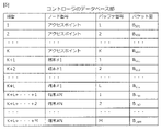
- FIG. 5 is a diagram illustrating an example of information arranged in the database unit 31. As shown in FIG. This database DB organizes the following three pieces of information.
- the item number is a serial number for all buffers (FB1, FB2) of the terminal 11 and the access point 12.
- FIG. A node number is the number of the terminal 11 .
- the buffer number is the number of the buffer FB1 held by each terminal 11 or the number of the buffer FB2 held by the access point 12 .
- the amount of packets is the accumulated amount of packets held by buffers having respective buffer numbers.
- the item number K+2 is the packet accumulation amount of the flow unit buffer unit FB1#2 of the terminal 11#1, and means that the amount is "B12".
- the terminal 11#N+1 is newly connected, the node number and buffer number of the terminal 11#N+1 are not stored in the database unit 31.
- Information about the access point 12 is stored in the database unit 31 when the access point 12 is installed. At this time, the protocol compatible with the access point 12 is also stored in the database unit 31 .
- FIG. 6 shows a configuration example of the terminal 11.
- the terminal 11 includes a database section 41 , a control signal transmission/reception section 42 and a scheduler section 43 .
- FIG. 7 shows an example of information stored in the database unit 41.
- the database unit 41 sorts out the node number of its own device and the information of the flow unit buffers FB1#1 to FB1#L.
- each terminal 11 records its own node number and buffer number in its own database section 41 .
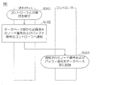
- FIG. 8 shows a flowchart when the terminal 11#N+1 newly connects.
- the newly connected terminal 11#N+1 Before connecting to the access point 12, the newly connected terminal 11#N+1 establishes connection with the controller 13 according to the connection sequence according to the protocol available in the wireless network 15 (S101).
- the newly connected terminal 11#N+1 After being connected to the controller 13, the newly connected terminal 11#N+1 notifies the controller 13 of the node number and buffer number recorded in the database unit 11 as the newly connected terminal (S102).
- the controller 13 records the node number #N+1 of the terminal 11#N+1 and the buffer number held by the terminal 11#N+1 in the database unit 31 (S103).
- the node numbers and buffer numbers of all the terminals 11#1 to 11#N+1 can be recorded in the controller 13 in advance.
- step S101 the protocol used when the controller 13 establishes connection with the terminal 11#N+1 follows the protocol of the wireless network 15 available to the terminal 11#N+1.
- the controller 13 receives a radio signal for the terminal 11#N+1 to search for the access point 12, and establishes a connection with the terminal 11#N+1 by a connection sequence according to a protocol adapted to the received radio signal.
- the communication between the terminal 11#N+1 and the controller 13 may use a different protocol from the data communication between the terminal 11#N+1 and the access point 12. For example, communication between terminal 11#N+1 and controller 13 uses a low-speed protocol that allows communication even when radio waves are weak, and communication between terminal 11#N+1 and access point 12 uses a high-speed protocol.
- the terminal 11 After step S103, the terminal 11 notifies the controller 13 of the band required by the application.
- the controller 13 records the notified required bandwidth in the database unit 31, determines the bandwidth control value for each traffic flow for each terminal 11 and access point 12 based on the recorded information in the database unit, and determines the bandwidth control value for each traffic flow for each terminal 11 and access point 12.
- Each terminal 11 and access point 12 transmits each traffic packet within the notified bandwidth control value range. Accordingly, the present disclosure enables band allocation for each fine traffic flow such as service or application in an actual wireless network.
- the newly connected terminal 11#N+1 does not know whether the node number and buffer number notified by itself are recorded in the controller 13 without fail. In normal communication, notification may be damaged or lost due to packet loss or the like. Therefore, in this embodiment, the controller 13 is reliably notified of the node number and buffer number of the terminal 11#N+1 to be newly connected.
- FIG. 9 shows a flowchart when the terminal 11#N+1 newly connects.
- the controller 13 notifies the newly connected terminal 11#N+1 of connection confirmation indicating that the data has been recorded in the database unit 31 (S201).
- the newly connected terminal 11#N+1 transmits the node number and the buffer number notified at the time of connection a plurality of times until the notification of connection confirmation arrives from the controller 13 (S202).
- the terminal 11#N+1 receives the connection confirmation notification, it notifies the controller 13 of the buffer size (S203).
- the controller 13 Even after the controller 13 has recorded the node number and buffer number of the terminal 11#N+1 in the database unit 31, it may still receive the node number and buffer number from the terminal 11#N+1. In such a case, the controller 13 resends the notification of connection confirmation.
- a control signal transmitting/receiving unit that transmits the accumulated amount of the transmission packets for each traffic flow accumulated in the buffers (FB1, FB2) to the controller 13, and receives the transmission time and transmission amount of the transmission packets for each traffic flow from the controller 13.
- (42, 22) and a main signal transmission unit (MTR1, MTR2) that transmits the transmission packet for each traffic flow in buffers (FB1, FB2) to a wireless network 15 according to the transmission time and the transmission amount;
- the control signal transmitting/receiving unit 32 receives the accumulated amount from each of the terminal 11 and the access point 12 and transmits the transmission time and the transmission amount to each of the terminal 11 and the access point 12 .
- the scheduling unit 33 determines the transmission time and the transmission amount of the transmission packet for each traffic flow based on the accumulated amount.
- Each terminal 11 and access point 12 periodically notifies the controller 13 of the amount of packets accumulated in the flow unit buffer units (FB1, FB2) as a control signal.
- the terminal 11 accumulates packets from each application AP1 in the buffer FB1 for each application (for each flow).
- the packet amount notification unit 44 periodically checks the amount of packets accumulated in each buffer FB1 and notifies the controller 13 of this as a control signal via the control signal transmission/reception unit 42 .
- the access point 12 accumulates packets from the upper network device 50 in the buffer FB2 for each application (for each flow).
- the packet amount notification unit 24 periodically checks the amount of packets accumulated in each buffer FB2 and notifies the controller 13 of this as a control signal via the control signal transmission/reception unit 22 .
- the application AP1 may own the flow unit buffer unit FB1.
- the controller 13 records the notified packet accumulation amount, the terminal 11, the access point 12, and the information of the flow unit buffers (FB1, FB2), determines the transmission time and transmission amount for each buffer based on it, It is notified to the terminal 11 and the access point 12 as a control signal.
- the control signal transmission/reception unit 32 of the controller 13 receives control signals from each terminal 11 and the access point 12, and determines the amount of accumulated packets contained in the control signal, the terminal 11, the access point 12, and the flow unit buffers (FB1, FB2). Organize the information in the database DB31.
- the scheduling unit 33 of the controller 13 uses the scheduling method described later to determine the transmission time and transmission amount for each buffer from the contents of the database unit DB31. Then, the scheduling unit 33 uses the determined transmission time and transmission amount as a control signal, and transmits the control signal transmission/reception unit 32 to the terminal 11 or the access point 12 .
- Each terminal 11 and access point 12 extracts the packets accumulated in the flow unit buffer units (FB1, FB2) at the notified transmission time and transmission amount and inputs them to the main signal buffer units (MB1, MB2).
- the main signal transmitting/receiving units (MTR1, MTR2) transmit the packets of the main signal buffer units (MB1, MB2) to the wireless network 15.
- FIG. 10 is a flowchart illustrating the operations described above.
- the control method of this embodiment is a control method for controlling the traffic of the wireless network 15,
- the control method is transmission control performed by the controller 13 on the terminal 11 and the access point 12 that mutually transmit packets via the wireless network 15, accumulating transmission packets for each traffic flow in respective buffers (FB1, FB2) of the terminal 11 and the access point 12 (steps S111, S112, S121, S122); transmitting to the controller the accumulated amount of the transmission packets for each traffic flow accumulated in each of the buffers (steps S113, S123); determining, by the controller, the transmission time and transmission amount of the transmission packet for each traffic flow based on the accumulated amount received from each of the terminal and the access point (steps S131 and S132); transmitting the transmission time and the transmission amount from the controller to each of the terminal and the access point (step S133); and traffic from the buffer of each of the terminal and the access point according to the transmission time and the transmission amount. transmitting the transmission packets for
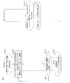
- FIG. 11 and 12 are diagrams for explaining the effect of the control system of the present disclosure.
- FIG. 11 is a sequence diagram of the control system of the present disclosure
- FIG. 12 is a sequence diagram of a conventional communication system in which the controller 13 does not exist.
- RTS Request To Send
- CTS Clear to Send
- a solid line means communication of the main signal
- a broken line means communication of the control signal.
- the communication operation from the main signal buffers (MB1, MB2) in FIG. 11 is the same as the communication operation in FIG.
- the control system of the present disclosure can be realized by arranging the controller 13 without modifying the existing communication system.
- the communication operation of FIG. 12 since there is no control of the transmission time, there is a problem that packet collision occurs and terminals and access points that can transmit are biased. Since the transmission time is controlled for , the above problem is resolved.
- the transmission amount S J [Bytes] of the per-flow buffer #J is The transmission time T J [sec] of the flow unit buffer #J is The transmission time t J [sec] of the flow unit buffer #J is is calculated as
- the order of the flow unit buffers to start transmission is, for example, starting from the lowest item number organized in the database unit DB31 of the controller 13.
- the transmission amount S J [Bytes] of the per-flow buffer #J is If T all ⁇ T, then If T all >T, then The transmission time T J [sec] of the flow unit buffer #J is If T all ⁇ T, then If T all >T, then The transmission time t J [sec] of the flow unit buffer #J is If T all ⁇ T, then If T all >T, then is calculated as
- This disclosure can be applied to the information and communications industry.
- Terminal 12 Access point 13: Controller 15: Wireless network 21, 31, 41: Database unit 22, 32, 42: Control signal transmission/reception unit 23, 43: Scheduler unit 24, 44: Packet amount notification unit 33: Scheduling unit
Landscapes
- Engineering & Computer Science (AREA)
- Computer Networks & Wireless Communication (AREA)
- Signal Processing (AREA)
- Mobile Radio Communication Systems (AREA)
Abstract
Description
無線ネットワークのトラフィックを制御する制御システムであって、
前記無線ネットワークを介してパケットを相互に伝送する端末及びアクセスポイントと、
前記端末及び前記アクセスポイントに対して送信制御を行うコントローラと、
を備えており、
前記端末は、自装置のノード番号及びフロー単位バッファの情報を予め保持し、
前記コントローラは、
前記アクセスポイントが前記端末と接続を確立する前に、前記無線ネットワークで利用可能なプロトコルによる接続シーケンスを用いて前記端末と接続を確立し、
前記端末から当該端末のノード番号及びフロー単位バッファの情報を、前記無線ネットワークを通して取得し、
前記アクセスポイントが前記端末と接続を確立した後に、前記無線ネットワークを通して取得した前記端末のノード番号及びフロー単位バッファの情報を用いて、前記端末のフロー単位バッファに蓄積されているトラフィックフロー毎に、送信制御を行う。
無線ネットワークのトラフィックを制御する制御方法であって、
前記制御方法は、前記無線ネットワークを介してパケットを相互に伝送する端末及びアクセスポイントに対してコントローラが行う送信制御であって、
前記アクセスポイントが前記端末と接続を確立する前に、
前記コントローラが、
前記無線ネットワークで利用可能なプロトコルによる接続シーケンスを用いて前記端末と接続を確立し、
前記端末から当該端末が予め保持している自装置のノード番号及びフロー単位バッファの情報を、前記無線ネットワークを通して取得し、
前記アクセスポイントが前記端末と接続を確立した後に、
前記コントローラが、前記無線ネットワークを通して取得した前記端末のノード番号及びフロー単位バッファの情報を用いて、前記端末のフロー単位バッファに蓄積されているトラフィックフロー毎に、送信制御を行う。
無線ネットワークのトラフィックを制御するコントローラであって、
前記コントローラは、前記無線ネットワークを介してパケットを相互に伝送する端末及びアクセスポイントに対して送信制御を行う装置であって、
前記アクセスポイントが前記端末と接続を確立する前に、
前記無線ネットワークで利用可能なプロトコルによる接続シーケンスを用いて前記端末と接続を確立し、
前記端末から当該端末が予め保持している自装置のノード番号及びフロー単位バッファの情報を、前記無線ネットワークを通して取得し、
前記アクセスポイントが前記端末と接続を確立した後に、
前記コントローラが、前記無線ネットワークを通して取得した前記端末のノード番号及びフロー単位バッファの情報を用いて、前記端末のフロー単位バッファに蓄積されているトラフィックフロー毎に、送信制御を行う。
図1に、本開示のシステム構成の一例を示す。本開示の通信ネットワークは、各端末11が無線ネットワーク15を通してアクセスポイント12と接続されている。本開示の制御システムは、この通信ネットワークを制御するコントローラ13を備える。コントローラ13は専用の制御網を通してアクセスポイント12と接続されている。コントローラ13は、無線ネットワーク15で利用可能なプロトコルによる接続シーケンスによって、各端末11と接続される。
項番は、端末11とアクセスポイント12の全てのバッファ(FB1、FB2)に対する通し番号である。
ノード番号は、端末11の番号である。
バッファ番号は、各端末11が保有するバッファFB1の番号、又はアクセスポイント12の保有するバッファFB2の番号である。
パケット量は、それぞれのバッファ番号を持つバッファが保持するパケット蓄積量である。例えば、項番K+2は、端末11#1が持つフロー単位バッファ部FB1#2のパケット蓄積量であり、その量は“B12”であることを意味する。
端末11#N+1が新規に接続される場合、端末11#N+1のノード番号及びバッファ番号はデータベース部31に格納されていない。
新規に接続される端末11#N+1は、アクセスポイント12に接続する前に、無線ネットワーク15で利用可能なプロトコルによる接続シーケンスに従って、コントローラ13と接続を確立する(S101)。
新規に接続される端末11#N+1は、コントローラ13との接続後、新規接続端末としてデータベース部11に記録されているノード番号およびバッファ番号をコントローラ13に通知する(S102)。
コントローラ13は、端末11#N+1のノード番号#N+1および端末11#N+1が保持するバッファ番号を、データベース部31に記録する(S103)。
これにより、コントローラ13に対して、事前に全端末11#1~11#N+1のノード番号及びバッファ番号を記録しておくことができる。
新規に接続される端末11#N+1にとって、自身が通知したノード番号およびバッファ番号がコントローラ13へ確実に記録されているかわからない。通常の通信ではパケットロスなどによって通知破損・損失する可能性がある。そこで、本実施形態では、新規に接続される端末11#N+1のノード番号およびバッファ番号を、確実にコントローラ13へ通知する。
コントローラ13は、データベース部31に記録した際にデータベース部へ記録したことを示す接続確認を、新規に接続される端末11#N+1へ通知する(S201)。
新規に接続される端末11#N+1は、接続時に通知するノード番号およびバッファ番号を、コントローラ13からの接続確認の通知が到着するまで複数回送信する(S202)。
端末11#N+1は、接続確認の通知が到着すると、コントローラ13へバッファ量を通知する(S203)。
端末11及びアクセスポイント12のそれぞれは、
送信パケットをトラフィックフロー毎に蓄積するバッファ(FB1、FB2)と、
バッファ(FB1、FB2)に蓄積されたトラフィックフロー毎の前記送信パケットの蓄積量をコントローラ13に送信し、コントローラ13からトラフィックフロー毎の前記送信パケットの送信時刻および送信量を受信する制御信号送受信部(42、22)と、
前記送信時刻および前記送信量に従ってバッファ(FB1、FB2)内のトラフィックフロー毎の前記送信パケットを無線ネットワーク15に送信する主信号送信部(MTR1、MTR2)と、
を備える。
制御信号送受信部32は、端末11及びアクセスポイント12のそれぞれから前記蓄積量を受信し、端末11及びアクセスポイント12のそれぞれへ前記送信時刻および前記送信量を送信する。スケジューリング部33は、前記蓄積量に基づいて、トラフィックフロー毎の前記送信パケットの前記送信時刻及び前記送信量を決定する。
端末11は各アプリケーションAP1からのパケットをアプリケーション毎(フロー毎)にバッファFB1に蓄積する。パケット量通知部44は、定期的に各バッファFB1のパケット蓄積量を確認し、これを制御信号として制御信号送受信部42を介してコントローラ13へ通知する。
また、アクセスポイント12は上位ネットワーク装置50からのパケットをアプリケーション毎(フロー毎)にバッファFB2に蓄積する。パケット量通知部24は、定期的に各バッファFB2のパケット蓄積量を確認し、これを制御信号として制御信号送受信部22を介してコントローラ13へ通知する。
なお、フロー単位バッファ部FB1をアプリケーションAP1が所有していてもよい。
前記制御方法は、無線ネットワーク15を介してパケットを相互に伝送する端末11及びアクセスポイント12に対してコントローラ13が行う送信制御であって、
端末11及びアクセスポイント12のそれぞれのバッファ(FB1、FB2)にトラフィックフロー毎に送信パケットを蓄積すること(ステップS111、S112、S121,S122)、
それぞれの前記バッファに蓄積されたトラフィックフロー毎の前記送信パケットの蓄積量を前記コントローラに送信すること(ステップS113、S123)、
前記コントローラにて、前記端末及び前記アクセスポイントのそれぞれから受信した前記蓄積量に基づいてトラフィックフロー毎の前記送信パケットの送信時刻及び送信量を決定すること(ステップS131、S132)、
前記コントローラから前記端末及び前記アクセスポイントのそれぞれへ前記送信時刻および前記送信量を送信すること(ステップS133)、及び
前記送信時刻および前記送信量に従って前記端末及び前記アクセスポイントのそれぞれの前記バッファからトラフィックフロー毎の前記送信パケットを前記無線ネットワークに送信すること(ステップS114、S124)
を特徴とする。
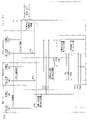
図11と図12は、本開示の制御システムの効果を説明する図である。図11は、本開示の制御システムのシーケンス図であり、図12は、コントローラ13が存在しない従来の通信システムにおけるシーケンス図である。図において、“RTS”は送信要求(Request To Send)、“CTS”は送信許可(Clear to Send)を意味する。また、実線は主信号の通信、破線は制御信号の通信を意味する。
ここで、コントローラ13のスケジューリング部33が行うスケジューリング方式を説明する。
[1]公平にスケジューリング
本スケジューリング方式は、端末11とアクセスポイント12のフロー単位バッファ(FB1、FB2)のうち、パケットが蓄積されているフロー単位バッファの総数で帯域や時間を割る計算を行う。
以下、パラメータを説明する。
端末11とアクセスポイント12を合わせた、パケットが蓄積されているフロー単位バッファの数: n
1cycleの時間: T[sec]
1cycle時間あたりの主信号総送信限界量: Z[Bytes/sec]
最初に蓄積されたパケットを送信する時刻: tstart[sec]
フロー単位バッファ#Jの送信量SJ[Bytes]は、


本スケジューリング方式は、端末11とアクセスポイント12のフロー単位バッファ(FB1、FB2)のうち、パケットが蓄積されているフロー単位バッファの数とそのパケット蓄積量で決定する。
以下、パラメータを説明する。
フロー単位バッファ#Jのパケット蓄積量: BJ[Bytes]
1cycleの時間: T[sec]
1cycle時間あたりの送信限界量: Z[Bytes/sec]
全フロー単位バッファに蓄積された全パケットを送信するために必要な時間: Tall[sec]
全フロー単位バッファに蓄積されたパケットのうち最初にパケット送信する時刻: tstart[sec]

フロー単位バッファ#Jの送信量SJ[Bytes]は、
Tall≦Tの場合、


Tall≦Tの場合、


Tall≦Tの場合、


12:アクセスポイント
13:コントローラ
15:無線ネットワーク
21、31、41:データベース部
22、32、42:制御信号送受信部
23、43:スケジューラ部
24、44:パケット量通知部
33:スケジューリング部
Claims (5)
- 無線ネットワークのトラフィックを制御する制御システムであって、
前記無線ネットワークを介してパケットを相互に伝送する端末及びアクセスポイントと、
前記端末及び前記アクセスポイントに対して送信制御を行うコントローラと、
を備えており、
前記端末は、自装置のノード番号及びフロー単位バッファの情報を予め保持し、
前記コントローラは、
前記アクセスポイントが前記端末と接続を確立する前に、前記無線ネットワークで利用可能なプロトコルによる接続シーケンスを用いて前記端末と接続を確立し、
前記端末から当該端末のノード番号及びフロー単位バッファの情報を、前記無線ネットワークを通して取得し、
前記アクセスポイントが前記端末と接続を確立した後に、前記無線ネットワークを通して取得した前記端末のノード番号及びフロー単位バッファの情報を用いて、前記端末のフロー単位バッファに蓄積されているトラフィックフロー毎に、送信制御を行う、
制御システム。 - 前記コントローラは、前記端末からノード番号及びフロー単位バッファの情報を取得すると、当該情報を取得したことを示す接続確認を、前記端末に通知する、
請求項1に記載の制御システム。 - 無線ネットワークのトラフィックを制御する制御方法であって、
前記制御方法は、前記無線ネットワークを介してパケットを相互に伝送する端末及びアクセスポイントに対してコントローラが行う送信制御であって、
前記アクセスポイントが前記端末と接続を確立する前に、
前記コントローラが、
前記無線ネットワークで利用可能なプロトコルによる接続シーケンスを用いて前記端末と接続を確立し、
前記端末から当該端末が予め保持している自装置のノード番号及びフロー単位バッファの情報を、前記無線ネットワークを通して取得し、
前記アクセスポイントが前記端末と接続を確立した後に、
前記コントローラが、前記無線ネットワークを通して取得した前記端末のノード番号及びフロー単位バッファの情報を用いて、前記端末のフロー単位バッファに蓄積されているトラフィックフロー毎に、送信制御を行う、
制御方法。 - 無線ネットワークのトラフィックを制御するコントローラであって、
前記コントローラは、前記無線ネットワークを介してパケットを相互に伝送する端末及びアクセスポイントに対して送信制御を行う装置であって、
前記アクセスポイントが前記端末と接続を確立する前に、
前記無線ネットワークで利用可能なプロトコルによる接続シーケンスを用いて前記端末と接続を確立し、
前記端末から当該端末が予め保持している自装置のノード番号及びフロー単位バッファの情報を、前記無線ネットワークを通して取得し、
前記アクセスポイントが前記端末と接続を確立した後に、
前記コントローラが、前記無線ネットワークを通して取得した前記端末のノード番号及びフロー単位バッファの情報を用いて、前記端末のフロー単位バッファに蓄積されているトラフィックフロー毎に、送信制御を行う、
コントローラ。 - 請求項4に記載のコントローラとしてコンピュータを機能させるためのプログラム。
Priority Applications (3)
| Application Number | Priority Date | Filing Date | Title |
|---|---|---|---|
| JP2023528914A JP7655386B2 (ja) | 2021-06-18 | 2021-06-18 | 制御システム、制御方法、コントローラ、及びプログラム |
| PCT/JP2021/023197 WO2022264403A1 (ja) | 2021-06-18 | 2021-06-18 | 制御システム、制御方法、コントローラ、及びプログラム |
| US18/564,404 US20240251294A1 (en) | 2021-06-18 | 2021-06-18 | Control system, control method, controller, and program |
Applications Claiming Priority (1)
| Application Number | Priority Date | Filing Date | Title |
|---|---|---|---|
| PCT/JP2021/023197 WO2022264403A1 (ja) | 2021-06-18 | 2021-06-18 | 制御システム、制御方法、コントローラ、及びプログラム |
Publications (1)
| Publication Number | Publication Date |
|---|---|
| WO2022264403A1 true WO2022264403A1 (ja) | 2022-12-22 |
Family
ID=84526949
Family Applications (1)
| Application Number | Title | Priority Date | Filing Date |
|---|---|---|---|
| PCT/JP2021/023197 Ceased WO2022264403A1 (ja) | 2021-06-18 | 2021-06-18 | 制御システム、制御方法、コントローラ、及びプログラム |
Country Status (3)
| Country | Link |
|---|---|
| US (1) | US20240251294A1 (ja) |
| JP (1) | JP7655386B2 (ja) |
| WO (1) | WO2022264403A1 (ja) |
Citations (1)
| Publication number | Priority date | Publication date | Assignee | Title |
|---|---|---|---|---|
| JP2015050774A (ja) * | 2013-09-04 | 2015-03-16 | 株式会社Nttドコモ | 無線システムにおけるソフトウェア定義フロー制御のための方法及び装置 |
-
2021
- 2021-06-18 JP JP2023528914A patent/JP7655386B2/ja active Active
- 2021-06-18 WO PCT/JP2021/023197 patent/WO2022264403A1/ja not_active Ceased
- 2021-06-18 US US18/564,404 patent/US20240251294A1/en active Pending
Patent Citations (1)
| Publication number | Priority date | Publication date | Assignee | Title |
|---|---|---|---|---|
| JP2015050774A (ja) * | 2013-09-04 | 2015-03-16 | 株式会社Nttドコモ | 無線システムにおけるソフトウェア定義フロー制御のための方法及び装置 |
Non-Patent Citations (1)
| Title |
|---|
| SAKAUE, YUKI ET AL.: "Proposal of centralized quality control independent of wireless network", PROCEEDINGS OF THE 2021 IEICE GENERAL CONFERENCE: COMMUNICATION, February 2021 (2021-02-01) * |
Also Published As
| Publication number | Publication date |
|---|---|
| JPWO2022264403A1 (ja) | 2022-12-22 |
| JP7655386B2 (ja) | 2025-04-02 |
| US20240251294A1 (en) | 2024-07-25 |
Similar Documents
| Publication | Publication Date | Title |
|---|---|---|
| US20070025304A1 (en) | System and method for prioritizing transmission legs for precaching data | |
| US7643790B2 (en) | Local communication system and method in wireless communication system | |
| JP7791250B2 (ja) | リンク選択方法および装置、ならびにコンピュータ可読記憶媒体 | |
| JP2004040824A (ja) | ワイヤレス可変帯域幅エアリンク装置と通信する移動通信用加入者装置及び方法 | |
| US9001748B2 (en) | Method for scheduling traffic of home node, and applied to the same | |
| US20060140146A1 (en) | Method for controlling data circuits | |
| US8300611B2 (en) | Method and apparatus to provide air time fairness in multiple physical transmission rate wireless systems | |
| WO2016105010A1 (ko) | 이동 통신 시스템에서 전송 차별화를 제공하는 방법 및 장치 | |
| WO2021191999A1 (ja) | 制御システム、制御方法、コントローラ、及びプログラム | |
| CN111132223B (zh) | 一种数据包的传输方法和通信设备 | |
| RU2324304C2 (ru) | Способ передачи данных и система, базовая станция, абонентская станция, блок обработки, компьютерный программный продукт, распространяемый носитель компьютерной программы и модуль исходных сигналов для его осуществления | |
| US20100118816A1 (en) | Apparatus and method for transmitting data in wireless communication system | |
| EP3697132B1 (en) | Handover of a latency critical application | |
| JP7655386B2 (ja) | 制御システム、制御方法、コントローラ、及びプログラム | |
| USRE40333E1 (en) | Resource optimization function in a data and telecommunication system | |
| WO2023188089A1 (ja) | 制御システム、制御方法、コントローラ、及びプログラム | |
| JP4025659B2 (ja) | 無線基地局、移動局、無線通信システム、及び無線通信方法 | |
| CN111970290B (zh) | 一种基于VoIP地空语音通信的多载波延时补偿方法 | |
| WO2023067768A1 (ja) | 制御システム、制御方法、コントローラ、及びプログラム | |
| JP7622819B2 (ja) | 制御システム、制御方法、コントローラ、及びプログラム | |
| CN102132602B (zh) | 对可变比特率(vbr)业务分配信道时间的方法、用于处理数据的装置及其方法 | |
| US12556973B2 (en) | Control system, control method, controller, and program | |
| CN101466120B (zh) | 网络中的通信方法 | |
| WO2022195651A1 (ja) | 制御システム、制御方法、コントローラ、及びプログラム | |
| WO2023276147A1 (ja) | コントローラ、通信システム、制御方法、及びプログラム |
Legal Events
| Date | Code | Title | Description |
|---|---|---|---|
| 121 | Ep: the epo has been informed by wipo that ep was designated in this application |
Ref document number: 21946078 Country of ref document: EP Kind code of ref document: A1 |
|
| WWE | Wipo information: entry into national phase |
Ref document number: 2023528914 Country of ref document: JP |
|
| WWE | Wipo information: entry into national phase |
Ref document number: 18564404 Country of ref document: US |
|
| NENP | Non-entry into the national phase |
Ref country code: DE |
|
| 122 | Ep: pct application non-entry in european phase |
Ref document number: 21946078 Country of ref document: EP Kind code of ref document: A1 |