WO2022264331A1 - 攻撃検知装置、敵対的サンプルパッチ検知システム、攻撃検知方法、及び、攻撃検知プログラム - Google Patents
攻撃検知装置、敵対的サンプルパッチ検知システム、攻撃検知方法、及び、攻撃検知プログラム Download PDFInfo
- Publication number
- WO2022264331A1 WO2022264331A1 PCT/JP2021/022916 JP2021022916W WO2022264331A1 WO 2022264331 A1 WO2022264331 A1 WO 2022264331A1 JP 2021022916 W JP2021022916 W JP 2021022916W WO 2022264331 A1 WO2022264331 A1 WO 2022264331A1
- Authority
- WO
- WIPO (PCT)
- Prior art keywords
- attack
- time
- image data
- detection device
- recognition score
- Prior art date
- Legal status (The legal status is an assumption and is not a legal conclusion. Google has not performed a legal analysis and makes no representation as to the accuracy of the status listed.)
- Ceased
Links
Images


Classifications
-
- H—ELECTRICITY
- H04—ELECTRIC COMMUNICATION TECHNIQUE
- H04L—TRANSMISSION OF DIGITAL INFORMATION, e.g. TELEGRAPHIC COMMUNICATION
- H04L63/00—Network architectures or network communication protocols for network security
- H04L63/14—Network architectures or network communication protocols for network security for detecting or protecting against malicious traffic
- H04L63/1408—Network architectures or network communication protocols for network security for detecting or protecting against malicious traffic by monitoring network traffic
-
- G—PHYSICS
- G06—COMPUTING OR CALCULATING; COUNTING
- G06N—COMPUTING ARRANGEMENTS BASED ON SPECIFIC COMPUTATIONAL MODELS
- G06N3/00—Computing arrangements based on biological models
- G06N3/02—Neural networks
-
- G—PHYSICS
- G06—COMPUTING OR CALCULATING; COUNTING
- G06V—IMAGE OR VIDEO RECOGNITION OR UNDERSTANDING
- G06V10/00—Arrangements for image or video recognition or understanding
- G06V10/70—Arrangements for image or video recognition or understanding using pattern recognition or machine learning
- G06V10/77—Processing image or video features in feature spaces; using data integration or data reduction, e.g. principal component analysis [PCA] or independent component analysis [ICA] or self-organising maps [SOM]; Blind source separation
- G06V10/776—Validation; Performance evaluation
-
- G—PHYSICS
- G06—COMPUTING OR CALCULATING; COUNTING
- G06V—IMAGE OR VIDEO RECOGNITION OR UNDERSTANDING
- G06V10/00—Arrangements for image or video recognition or understanding
- G06V10/70—Arrangements for image or video recognition or understanding using pattern recognition or machine learning
- G06V10/82—Arrangements for image or video recognition or understanding using pattern recognition or machine learning using neural networks
Definitions
- the present disclosure relates to an attack detection device, a hostile sample patch detection system, an attack detection method, and an attack detection program.
- Non-Patent Document 1 physically arranges hostile sample patches printed with an image to which electronic perturbation is added, and performs detection by object detection when an image obtained by photographing the arranged hostile sample patches is input. A technique for escaping adversarial sample patch attacks is disclosed.
- the purpose of this disclosure is to detect a hostile sample patch attack when it occurs.
- the attack detection device is A plurality of recognition scores calculated using each of a plurality of image data obtained by photographing a range within the photographing range at different times within the photographing time range, and indicating the result of detecting an object in each of the plurality of image data.
- a time-series recognition score which is time-series data generated using a plurality of recognition scores, includes an abnormal pattern that occurs when a hostile sample patch attack is performed on at least one of the plurality of image data.
- an abnormal pattern detection unit that detects whether or not the
- the attack detection device detects whether an abnormal pattern that occurs when a hostile sample patch attack is implemented is included in a time-series recognition score composed of recognition scores indicating the result of detecting an object.
- An abnormal pattern detector is provided. Therefore, according to the present disclosure, when a hostile sample patch attack is performed, the attack can be detected.
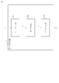
- FIG. 1 is a diagram showing a system configuration example of a hostile sample patch detection system 100 according to Embodiment 1;
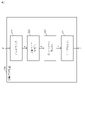
- FIG. 2 is a diagram showing a functional configuration example of an object detection device 110 according to Embodiment 1;
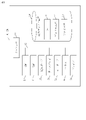
- FIG. FIG. 2 is a diagram showing a functional configuration example of an attack detection device 120 according to Embodiment 1;
- FIG. FIG. 2 is a diagram showing a hardware configuration example of each of an object detection device 110 and an attack detection device 120 according to Embodiment 1;
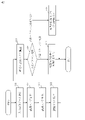
- 4 is a flowchart showing the operation of the hostile sample patch detection system 100 according to Embodiment 1;
- FIG. 4 is a diagram showing a hardware configuration example of each of an object detection device 110 and an attack detection device 120 according to a modification of Embodiment 1;
- FIG. 1 shows a system configuration example of a hostile sample patch detection system 100 according to this embodiment.
- the hostile sample patch detection system 100 has an object detection device 110 and an attack detection device 120 .
- the object detection device 110 and the attack detection device 120 may be configured integrally.
- the object detection device 110 receives input image data x as an input, and outputs a recognition score y that is an object detection result.
- the attack detection device 120 receives the recognition score y as an input, and detects a hostile sample patch attack as a detection result r of the hostile sample patch attack when an abnormal pattern of recognition scores due to the hostile sample patch attack is detected. It will output a result indicating that it has detected a hostile sample patch attack otherwise.
- a hostile sample patch attack is a kind of hostile sample attack, and is an attack that avoids object detection using a neural network or the like.
- a specific example of the abnormal pattern is a pattern in which the value of the recognition score continues for a certain period of time and is slightly below the object detection threshold. That is, the anomaly pattern is a pattern indicating that the time for which the value of the recognition score indicated by the time-series recognition score is less than the object detection threshold and equal to or greater than the anomaly detection threshold continues for an anomaly detection time or longer. Attacks using current adversarial sample patches can reduce the value of the recognition score to below the threshold for object detection, but not completely zero. Therefore, this abnormal pattern is effective in detecting the attack.
- the abnormal pattern is not limited only to this pattern.
- FIG. 2 shows an example of the functional configuration of the object detection device 110.
- the object detection device 110 has a data input section 111 , an object detector 112 and a data output section 113 .
- the data input unit 111 receives input image data x, which is a target of object detection, and inputs the received input image data x to the object detector 112 .
- the object detector 112 calculates a recognition score y using the inputted input image data x, and outputs the calculated recognition score y to the data output unit 113 .
- the object detector 112 is an object detector 112 constructed by a neural network as a specific example.
- neural networks include YOLO (You Only Look Once), SSD (Single Shot Multibox Detector), and Faster R-CNN (Region-based Convolutional Neural Networks).
- the object detector 112 outputs, as a recognition score, the coordinates representing the position of the bounding box corresponding to each object appearing in the input image, and the probability representing the type and certainty of the object within each bounding box.
- the object detector 112 calculates multiple recognition scores using each of the multiple image data.
- the object detector 112 is also called an object detector.
- a data output unit 113 outputs the recognition score y calculated by the object detector 112 .
- FIG. 3 shows a functional configuration example of the attack detection device 120.
- the attack detection device 120 has a data input unit 121 , a recognition score accumulation unit 122 , an abnormal pattern detection unit 123 and a data output unit 124 .
- the data input unit 121 receives the recognition score y and inputs the received recognition score y to the recognition score accumulation unit 122 .
- the recognition score accumulation unit 122 generates a time-series recognition score Y by adding the input recognition score y to the time-series recognition score Y′, and inputs the generated time-series recognition score Y to the abnormal pattern detection unit 123. .
- the time-series recognition score Y corresponds to the updated time-series recognition score Y'.
- the time-series recognition score Y' is time-series data generated by accumulating the recognition scores y input until a new recognition score y is input.
- the recognition score accumulation unit 122 does not have to input the time series recognition score Y to the abnormal pattern detection unit 123 each time the recognition score y is input to the recognition score accumulation unit 122. may retrieve the latest time-series recognition score Y from the recognition score accumulation unit 122 and use the time-series recognition score Y thus retrieved.
- a time-series recognition score is time-series data generated using a plurality of recognition scores.
- a plurality of recognition scores are calculated using each of a plurality of image data obtained by photographing a range within the photographing range at different times within the photographing time range, and indicate results of object detection in each of the plurality of image data. .
- the abnormal pattern detection unit 123 matches the time-series recognition score Y with a previously specified abnormal pattern. As the detection result r, the abnormal pattern detection unit 123 detects the time-series recognition score Y when it matches the abnormal pattern, and when the time-series recognition score Y does not match the abnormal pattern, it detects a hostile sample. A result indicating that no patch attack has been detected is input to the data output unit 124 .
- the abnormal pattern detection unit 123 determines that an attack by a hostile sample patch has been performed when detecting an abnormal pattern that is a transition different from the normal transition of the recognition score.
- the abnormal pattern detection unit 123 detects whether or not the time-series recognition score includes an abnormal pattern that occurs when a hostile sample patch attack is performed on at least one of the plurality of image data.
- the data output unit 124 outputs the input detection result r.
- FIG. 4 is a diagram showing an example of hardware resources of each of the object detection device 110 and the attack detection device 120 according to this embodiment.
- Each of the object detection device 110 and the attack detection device 120 consists of a computer, and may consist of a plurality of computers.
- Each of the object detection device 110 and the attack detection device 120 includes a processor 11.
- the processor 11 communicates with a ROM 13, a RAM 14, a communication board 15, a display 51 as a display device, a keyboard 52, a mouse 53, a drive 54, and hardware devices such as a magnetic disk device 20 via a bus 12. connected to and controlling these hardware devices.
- the processor 11 is an IC (Integrated Circuit) that performs arithmetic processing, and specific examples include a CPU (Central Processing Unit), a DSP (Digital Signal Processor), or a GPU (Graphics Processing Unit).
- Each of the object detection device 110 and the attack detection device 120 may comprise multiple processors. A plurality of processors share the role of processor 11 .
- the drive 54 is a device that reads and writes storage media such as FD (Flexible Disk Drive), CD (Compact Disc), or DVD (Digital Versatile Disc).
- FD Flexible Disk Drive
- CD Compact Disc
- DVD Digital Versatile Disc
- Each of the ROM 13, RAM 14, magnetic disk device 20, and drive 54 is an example of a storage device.
- the storage device may be independent of the computer.
- the keyboard 52, mouse 53, and communication board 15 are examples of input devices.
- the display 51 and communication board 15 are examples of output devices.
- the communication board 15 is wired or wirelessly connected to a communication network such as a LAN (Local Area Network), the Internet, or a telephone line.
- the communication board 15 consists of a communication chip or NIC (Network Interface Card) as a specific example.
- the magnetic disk device 20 stores an OS (operating system) 21, a program group 22, and a file group 23.
- OS operating system
- the program group 22 includes programs that execute functions described as each part or each device in the present embodiment.
- the program is read and executed by processor 11 . That is, the program causes the computer to function as each part or each device, and causes the computer to execute the procedure or method of each part or each device.
- Any program described in this specification may be recorded in a computer-readable non-volatile recording medium.
- a nonvolatile recording medium is, for example, an optical disk or a flash memory. Any program described herein may be provided as a program product.
- the file group 23 includes various data used in each unit or device described in this embodiment.
- An operation procedure of the object detection device 110 corresponds to an object detection method.
- a program that implements the operation of the object detection device 110 corresponds to an object detection program.
- the operation procedure of the attack detection device 120 corresponds to an attack detection method.
- a program that implements the operation of the attack detection device 120 corresponds to an attack detection program.
- FIG. 5 is a flowchart showing an example of processing of the hostile sample patch detection system 100 according to this embodiment. The processing of the hostile sample patch detection system 100 will be described with reference to this figure.
- Step S11 The data input unit 111 receives input image data x and inputs the received input image data x to the object detector 112 .
- Step S12 The object detector 112 calculates a recognition score y using the inputted input image data x.
- Step S13 The data output unit 113 outputs the calculated recognition score y.
- Step S14 The data input unit 121 receives the recognition score y and inputs the received recognition score y to the recognition score accumulation unit 122 .
- the recognition score accumulation unit 122 updates the time-series recognition score Y′ to the time-series recognition score Y by adding the input recognition score y to the time-series recognition score Y′, and updates the time-series recognition score Y to the time-series recognition score Y′. Input to the pattern detection unit 123 .
- Step S16 The abnormal pattern detection unit 123 determines whether or not the input time-series recognition score Y matches a previously specified abnormal pattern. If the abnormal pattern matches the time-series recognition score Y, the attack detection device 120 proceeds to step S17. Otherwise, the attack detection device 120 proceeds to step S18.
- Step S17 The data output unit 124 outputs a result indicating that a hostile sample patch attack has been detected as the detection result r.
- Step S18 The data output unit 124 outputs, as the detection result r, a result indicating that no hostile sample patch attack has been detected.
- a hostile sample patch attack can be detected by determining whether or not the time-series recognition score matches an abnormal pattern.
- FIG. 6 shows a hardware configuration example of each of the object detection device 110 and the attack detection device 120 according to this modification.
- Each of the object detection device 110 and the attack detection device 120 includes a processing circuit 18 instead of the processor 11 , the processor 11 and the ROM 13 , the processor 11 and the RAM 14 , or the processor 11 , the ROM 13 and the RAM 14 .
- the processing circuit 18 is hardware that implements at least a part of each unit included in each of the object detection device 110 and the attack detection device 120 .
- the processing circuit 18 may be dedicated hardware, or may be a processor that executes programs stored in the magnetic disk device 20 .
- the processing circuit 18 may be, for example, a single circuit, a composite circuit, a programmed processor, a parallel programmed processor, an ASIC (Application Specific Integrated Circuit), an FPGA (Field Programmable Gate Array) or a combination thereof.
- Each of object detection device 110 and attack detection device 120 may include a plurality of processing circuits that substitute for processing circuit 18 .
- a plurality of processing circuits share the role of processing circuit 18 .
- the processing circuit 18 is implemented by hardware, software, firmware, or a combination thereof, as a specific example.
- the processor 11, ROM 13, RAM 14 and processing circuitry 18 are collectively referred to as "processing circuitry".
- processing circuitry the function of each functional component of the object detection device 110 and the attack detection device 120 is implemented by processing circuitry.
- Embodiment 1 has been described, a plurality of portions of this embodiment may be combined for implementation. Alternatively, this embodiment may be partially implemented. In addition, the present embodiment may be modified in various ways as necessary, and may be implemented in any combination as a whole or in part. What is described as each unit or device may be implemented in firmware, software, hardware, or a combination thereof. The above-described embodiments are essentially preferable examples, and are not intended to limit the scope of the present disclosure, its applications, and uses. The procedures described using flowcharts and the like may be changed as appropriate.
Landscapes
- Engineering & Computer Science (AREA)
- Theoretical Computer Science (AREA)
- Evolutionary Computation (AREA)
- Computing Systems (AREA)
- Physics & Mathematics (AREA)
- Software Systems (AREA)
- Health & Medical Sciences (AREA)
- Artificial Intelligence (AREA)
- General Health & Medical Sciences (AREA)
- General Physics & Mathematics (AREA)
- Computer Security & Cryptography (AREA)
- Computer Vision & Pattern Recognition (AREA)
- Databases & Information Systems (AREA)
- Multimedia (AREA)
- Medical Informatics (AREA)
- General Engineering & Computer Science (AREA)
- Computer Networks & Wireless Communication (AREA)
- Computer Hardware Design (AREA)
- Signal Processing (AREA)
- Life Sciences & Earth Sciences (AREA)
- Biomedical Technology (AREA)
- Biophysics (AREA)
- Computational Linguistics (AREA)
- Data Mining & Analysis (AREA)
- Molecular Biology (AREA)
- Mathematical Physics (AREA)
- Image Analysis (AREA)
- Burglar Alarm Systems (AREA)
Abstract
Description
撮影時間範囲内の互いに異なる時刻に撮影範囲内の範囲を撮影した複数の画像データそれぞれを用いて計算された複数の認識スコアであって、前記複数の画像データそれぞれにおいて物体を検知した結果を示す複数の認識スコアを用いて生成された時系列データである時系列認識スコアに、敵対的サンプルパッチ攻撃が前記複数の画像データの少なくともいずれかに対して実施された場合において生じる異常パターンが含まれているか否かを検知する異常パターン検知部
を備える。
以下、本実施の形態について、図面を参照しながら詳細に説明する。
図1は、本実施の形態に係る敵対的サンプルパッチ検知システム100のシステム構成例を示している。敵対的サンプルパッチ検知システム100は、物体検知装置110と攻撃検知装置120とを有する。物体検知装置110と攻撃検知装置120とは一体的に構成されてもよい。
物体検知装置110は、入力画像データxを入力として受け取り、物体検知結果である認識スコアyを出力する。
攻撃検知装置120は、認識スコアyを入力として受け取り、敵対的サンプルパッチ攻撃の検知結果rとして、敵対的サンプルパッチ攻撃による認識スコアの異常パターンが検知された場合には敵対的サンプルパッチ攻撃を検知したことを示す結果、それ以外の場合には敵対的サンプルパッチ攻撃を検知していないことを示す結果を出力する。敵対的サンプルパッチ攻撃は、敵対的サンプル攻撃の一種であり、特にニューラルネットワーク等を用いた物体検知を逃れる攻撃である。異常パターンは、具体例として、認識スコアの値が、一定時間継続して物体検知の閾値を多少下回る値であるパターンである。即ち、異常パターンは、時系列認識スコアが示す認識スコアの値が物体検知閾値未満異常検知閾値以上である時間が異常検知時間以上継続することを示すパターンである。現状の敵対的サンプルパッチを用いた攻撃では、認識スコアの値を、物体検知の閾値を下回るよう抑えることができるが、完全に0にすることはできない。そのため、この異常パターンは当該攻撃の検知において有効である。ただし、異常パターンはこのパターンのみに限定されない。
データ入力部111は、物体検知の対象である入力画像データxを受け取り、受け取った入力画像データxを物体検知器112に入力する。
物体検知器112は、入力された入力画像データxを用いて認識スコアyを算出し、算出した認識スコアyをデータ出力部113に出力する。物体検知器112は、具体例としてニューラルネットワークによって構築された物体検知器112である。ニューラルネットワークは、具体例として、YOLO(You Only Look Once)、SSD(Single Shot Multibox Detector)、又はFaster R-CNN(Region-based Convolutional Neural Networks)等である。物体検知器112は、入力された画像に映る各オブジェクトに対応するバウンディングボックスの位置を表す座標と、各バウンディングボックス内のオブジェクトの種類及び確信度を示す確率を認識スコアとして出力する。物体検知器112は、複数の画像データそれぞれを用いて複数の認識スコアを計算する。物体検知器112は物体検知部とも呼ばれる。
データ出力部113は、物体検知器112が計算した認識スコアyを出力する。
データ入力部121は、認識スコアyを受け取り、受け取った認識スコアyを認識スコア集積部122に入力する。
認識スコア集積部122は、入力された認識スコアyを時系列認識スコアY’に追加することによって時系列認識スコアYを生成し、生成した時系列認識スコアYを異常パターン検知部123に入力する。時系列認識スコアYは更新された時系列認識スコアY’に当たる。時系列認識スコアY’は、新たな認識スコアyが入力されるまでに入力された認識スコアyを集積して生成した時系列データである。認識スコア集積部122は、認識スコア集積部122に認識スコアyが入力される度に時系列認識スコアYを異常パターン検知部123に入力しなくてもよく、一定時間毎に異常パターン検知部123が認識スコア集積部122から最新の時系列認識スコアYを取り出し、取り出した時系列認識スコアYを用いてもよい。時系列認識スコアは、複数の認識スコアを用いて生成された時系列データである。複数の認識スコアは、撮影時間範囲内の互いに異なる時刻に撮影範囲内の範囲を撮影した複数の画像データそれぞれを用いて計算され、また、当該複数の画像データそれぞれにおいて物体を検知した結果を示す。
異常パターン検知部123は、時系列認識スコアYに対して事前に指定された異常パターンとのマッチングを行う。異常パターン検知部123は、検知結果rとして、時系列認識スコアYが異常パターンに合致する場合には検知したことを示す結果、時系列認識スコアYが異常パターンに合致しない場合には敵対的サンプルパッチ攻撃を検知していないことを示す結果をデータ出力部124に入力する。異常パターン検知部123は、通常時の認識スコアの推移と異なる推移である異常パターンを検知した際に敵対的サンプルパッチによる攻撃が行われたと判定する。異常パターン検知部123は、時系列認識スコアに、敵対的サンプルパッチ攻撃が複数の画像データの少なくともいずれかに対して実施された場合において生じる異常パターンが含まれているか否かを検知する。
データ出力部124は、入力された検知結果rを出力する。
本明細書に記載されているいずれのプログラムも、コンピュータが読み取り可能な不揮発性の記録媒体に記録されていてもよい。不揮発性の記録媒体は、具体例として、光ディスク又はフラッシュメモリである。本明細書に記載されているいずれのプログラムも、プログラムプロダクトとして提供されてもよい。
物体検知装置110の動作手順は、物体検知方法に相当する。また、物体検知装置110の動作を実現するプログラムは、物体検知プログラムに相当する。攻撃検知装置120の動作手順は、攻撃検知方法に相当する。また、攻撃検知装置120の動作を実現するプログラムは、攻撃検知プログラムに相当する。
データ入力部111は、入力画像データxを受け取り、受け取った入力画像データxを物体検知器112に入力する。
物体検知器112は、入力された入力画像データxを用いて認識スコアyを算出する。
データ出力部113は、算出された認識スコアyを出力する。
データ入力部121は、認識スコアyを受け取り、受け取った認識スコアyを認識スコア集積部122に入力する。
認識スコア集積部122は、入力された認識スコアyを時系列認識スコアY’に追加することによって時系列認識スコアY’を時系列認識スコアYに更新し、更新した時系列認識スコアYを異常パターン検知部123に入力する。
異常パターン検知部123は、入力された時系列認識スコアYが事前に指定された異常パターンに合致するか否かを判定する。
異常パターンが時系列認識スコアYに合致する場合、攻撃検知装置120はステップS17に進む。それ以外の場合、攻撃検知装置120はステップS18に進む。
データ出力部124は、検知結果rとして、敵対的サンプルパッチ攻撃を検知したことを示す結果を出力する。
データ出力部124は、検知結果rとして、敵対的サンプルパッチ攻撃を検知していないことを示す結果を出力する。
以上のように、本実施の形態によれば、時系列認識スコアが異常パターンに合致するか否かを判定することによって敵対的サンプルパッチ攻撃を検知することができる。
<変形例1>
図6は、本変形例に係る物体検知装置110及び攻撃検知装置120の各々のハードウェア構成例を示している。
物体検知装置110及び攻撃検知装置120の各々は、プロセッサ11、プロセッサ11とROM13、プロセッサ11とRAM14、あるいはプロセッサ11とROM13とRAM14とに代えて、処理回路18を備える。
処理回路18は、物体検知装置110及び攻撃検知装置120の各々が備える各部の少なくとも一部を実現するハードウェアである。
処理回路18は、専用のハードウェアであってもよく、また、磁気ディスク装置20に格納されるプログラムを実行するプロセッサであってもよい。
物体検知装置110及び攻撃検知装置120の各々は、処理回路18を代替する複数の処理回路を備えてもよい。複数の処理回路は、処理回路18の役割を分担する。
プロセッサ11とROM13とRAM14と処理回路18とを、総称して「プロセッシングサーキットリー」という。つまり、物体検知装置110及び攻撃検知装置120の各々の各機能構成要素の機能は、プロセッシングサーキットリーにより実現される。
実施の形態1について説明したが、本実施の形態のうち、複数の部分を組み合わせて実施しても構わない。あるいは、本実施の形態を部分的に実施しても構わない。その他、本実施の形態は、必要に応じて種々の変更がなされても構わず、全体としてあるいは部分的に、どのように組み合わせて実施されても構わない。各部又は各器として説明するものは、ファームウェア、ソフトウェア、ハードウェア又はこれらの組み合わせのいずれで実装されても構わない。
なお、前述した実施の形態は、本質的に好ましい例示であって、本開示と、その適用物と、用途の範囲とを制限することを意図するものではない。フローチャート等を用いて説明した手順は、適宜変更されてもよい。
Claims (5)
- 撮影時間範囲内の互いに異なる時刻に撮影範囲内の範囲を撮影した複数の画像データそれぞれを用いて計算された複数の認識スコアであって、前記複数の画像データそれぞれにおいて物体を検知した結果を示す複数の認識スコアを用いて生成された時系列データである時系列認識スコアに、敵対的サンプルパッチ攻撃が前記複数の画像データの少なくともいずれかに対して実施された場合において生じる異常パターンが含まれているか否かを検知する異常パターン検知部
を備える攻撃検知装置。 - 前記異常パターンは、前記時系列認識スコアが示す認識スコアの値が物体検知閾値未満異常検知閾値以上である時間が異常検知時間以上継続することを示すパターンである請求項1に記載の攻撃検知装置。
- 請求項1又は2に記載の攻撃検知装置と、
前記複数の画像データそれぞれを用いて前記複数の認識スコアを計算する物体検知部を備える物体検知装置と
を備える敵対的サンプルパッチ検知システム。 - 撮影時間範囲内の互いに異なる時刻に撮影範囲内の範囲を撮影した複数の画像データそれぞれを用いて計算された複数の認識スコアであって、前記複数の画像データそれぞれにおいて物体を検知した結果を示す複数の認識スコアを用いて生成された時系列データである時系列認識スコアに、敵対的サンプルパッチ攻撃が前記複数の画像データの少なくともいずれかに対して実施された場合において生じる異常パターンが含まれているか否かを検知する攻撃検知方法。
- 撮影時間範囲内の互いに異なる時刻に撮影範囲内の範囲を撮影した複数の画像データそれぞれを用いて計算された複数の認識スコアであって、前記複数の画像データそれぞれにおいて物体を検知した結果を示す複数の認識スコアを用いて生成された時系列データである時系列認識スコアに、敵対的サンプルパッチ攻撃が前記複数の画像データの少なくともいずれかに対して実施された場合において生じる異常パターンが含まれているか否かを検知する異常パターン検知処理
をコンピュータである攻撃検知装置に実行させる攻撃検知プログラム。
Priority Applications (5)
| Application Number | Priority Date | Filing Date | Title |
|---|---|---|---|
| JP2023527359A JP7309101B2 (ja) | 2021-06-16 | 2021-06-16 | 攻撃検知装置、敵対的サンプルパッチ検知システム、攻撃検知方法、及び、攻撃検知プログラム |
| DE112021007504.7T DE112021007504T5 (de) | 2021-06-16 | 2021-06-16 | Angriffserfassungseinrichtung, schädliches-sample-patch- erfassungssystem, angriffserfassungsverfahren und angriffserfassungsprogramm |
| CN202180099131.8A CN117425898B (zh) | 2021-06-16 | 2021-06-16 | 攻击检测装置、对抗样本补丁检测系统、攻击检测方法以及计算机能读取的记录介质 |
| PCT/JP2021/022916 WO2022264331A1 (ja) | 2021-06-16 | 2021-06-16 | 攻撃検知装置、敵対的サンプルパッチ検知システム、攻撃検知方法、及び、攻撃検知プログラム |
| US18/385,112 US12537826B2 (en) | 2021-06-16 | 2023-10-30 | Attack detection device, adversarial sample patch detection system, attack detection method, and non-transitory computer readable medium |
Applications Claiming Priority (1)
| Application Number | Priority Date | Filing Date | Title |
|---|---|---|---|
| PCT/JP2021/022916 WO2022264331A1 (ja) | 2021-06-16 | 2021-06-16 | 攻撃検知装置、敵対的サンプルパッチ検知システム、攻撃検知方法、及び、攻撃検知プログラム |
Related Child Applications (1)
| Application Number | Title | Priority Date | Filing Date |
|---|---|---|---|
| US18/385,112 Continuation US12537826B2 (en) | 2021-06-16 | 2023-10-30 | Attack detection device, adversarial sample patch detection system, attack detection method, and non-transitory computer readable medium |
Publications (1)
| Publication Number | Publication Date |
|---|---|
| WO2022264331A1 true WO2022264331A1 (ja) | 2022-12-22 |
Family
ID=84526462
Family Applications (1)
| Application Number | Title | Priority Date | Filing Date |
|---|---|---|---|
| PCT/JP2021/022916 Ceased WO2022264331A1 (ja) | 2021-06-16 | 2021-06-16 | 攻撃検知装置、敵対的サンプルパッチ検知システム、攻撃検知方法、及び、攻撃検知プログラム |
Country Status (5)
| Country | Link |
|---|---|
| US (1) | US12537826B2 (ja) |
| JP (1) | JP7309101B2 (ja) |
| CN (1) | CN117425898B (ja) |
| DE (1) | DE112021007504T5 (ja) |
| WO (1) | WO2022264331A1 (ja) |
Cited By (1)
| Publication number | Priority date | Publication date | Assignee | Title |
|---|---|---|---|---|
| EP4589455A1 (en) | 2024-01-21 | 2025-07-23 | Fujitsu Limited | Information processing program, information processing method, and information processing device |
Families Citing this family (2)
| Publication number | Priority date | Publication date | Assignee | Title |
|---|---|---|---|---|
| US12464018B2 (en) * | 2023-12-29 | 2025-11-04 | Robert Bosch Gmbh | System and method for high-resolution blackbox patch attack with Bayesian optimization |
| US12536300B2 (en) | 2023-12-29 | 2026-01-27 | Robert Bosch Gmbh | System and method for query efficient blackbox physically realizable attack with bayesian optimization |
Citations (1)
| Publication number | Priority date | Publication date | Assignee | Title |
|---|---|---|---|---|
| JP2019125867A (ja) * | 2018-01-12 | 2019-07-25 | パナソニックIpマネジメント株式会社 | 監視装置、監視システム及び監視方法 |
Family Cites Families (15)
| Publication number | Priority date | Publication date | Assignee | Title |
|---|---|---|---|---|
| WO2013014987A1 (ja) | 2011-07-25 | 2013-01-31 | インターナショナル・ビジネス・マシーンズ・コーポレーション | 情報識別方法、プログラム及びシステム |
| US9779361B2 (en) * | 2014-06-05 | 2017-10-03 | Mitsubishi Electric Research Laboratories, Inc. | Method for learning exemplars for anomaly detection |
| EP3376468B1 (en) * | 2015-12-02 | 2020-01-29 | Mitsubishi Electric Corporation | Object detection device and object detection method |
| JP6822328B2 (ja) | 2017-06-27 | 2021-01-27 | オムロン株式会社 | 見守り支援システム及びその制御方法 |
| JP2019061577A (ja) * | 2017-09-27 | 2019-04-18 | パナソニックIpマネジメント株式会社 | 異常判定方法及びプログラム |
| DE102017217733A1 (de) * | 2017-10-05 | 2019-04-11 | Conti Temic Microelectronic Gmbh | Prüfen eines neuronalen Netzes |
| JP7047372B2 (ja) | 2017-12-21 | 2022-04-05 | 東レ株式会社 | データ識別装置およびデータ識別方法 |
| US10915631B2 (en) * | 2017-12-28 | 2021-02-09 | Intel Corporation | Deep learning on execution trace data for exploit detection |
| US10944767B2 (en) * | 2018-02-01 | 2021-03-09 | International Business Machines Corporation | Identifying artificial artifacts in input data to detect adversarial attacks |
| JP7183904B2 (ja) | 2019-03-26 | 2022-12-06 | 日本電信電話株式会社 | 評価装置、評価方法、および、評価プログラム |
| US11681796B2 (en) * | 2019-09-10 | 2023-06-20 | International Business Machines Corporation | Learning input preprocessing to harden machine learning models |
| US11727109B2 (en) * | 2020-01-24 | 2023-08-15 | International Business Machines Corporation | Identifying adversarial attacks with advanced subset scanning |
| CN111340008B (zh) * | 2020-05-15 | 2021-02-19 | 支付宝(杭州)信息技术有限公司 | 对抗补丁生成、检测模型训练、对抗补丁防御方法及系统 |
| US12019747B2 (en) * | 2020-10-13 | 2024-06-25 | International Business Machines Corporation | Adversarial interpolation backdoor detection |
| CN116109521B (zh) * | 2023-04-07 | 2023-07-14 | 北京建筑大学 | 局部对抗性攻击启发式防御方法和装置 |
-
2021
- 2021-06-16 CN CN202180099131.8A patent/CN117425898B/zh active Active
- 2021-06-16 JP JP2023527359A patent/JP7309101B2/ja active Active
- 2021-06-16 DE DE112021007504.7T patent/DE112021007504T5/de active Pending
- 2021-06-16 WO PCT/JP2021/022916 patent/WO2022264331A1/ja not_active Ceased
-
2023
- 2023-10-30 US US18/385,112 patent/US12537826B2/en active Active
Patent Citations (1)
| Publication number | Priority date | Publication date | Assignee | Title |
|---|---|---|---|---|
| JP2019125867A (ja) * | 2018-01-12 | 2019-07-25 | パナソニックIpマネジメント株式会社 | 監視装置、監視システム及び監視方法 |
Non-Patent Citations (3)
| Title |
|---|
| DOSHI KEYAL, YASIN YILMAZ: "Continual Learning for Anomaly Detection in Surveillance Videos. arXiv.org", ARXIV:2004.07941, 15 April 2020 (2020-04-15), XP093017416, Retrieved from the Internet <URL:https://arxiv.org/pdf/2004.07941.pdf> [retrieved on 20230125] * |
| JI NAN, YANFEI FENG, HAIDONG XIE, XUESHUANG XIANG, NAIJIN LIU: "Adversarial YOLO: Defense Human Detection Patch Attacks via Detecting Adversarial Patches. arXiv.org", ARXIV:2103.08860, 16 March 2021 (2021-03-16), XP093017429, Retrieved from the Internet <URL:https://arxiv.org/abs/2103.08860> [retrieved on 20230125] * |
| XIAO, C. ET AL.: "AdvIT: Adversarial Frames Identifier Based on Temporal Consistency in Videos", PROCEEDINGS OF 2019 IEEE /CVF INTERNATIONAL CONFERENCE ON COMPUTER VISION (ICCV, 27 October 2019 (2019-10-27), pages 3967 - 3976, XP033723918, Retrieved from the Internet <URL:https://ieeexplore.ieee.org/document/9010733> [retrieved on 20210827], DOI: 10.1109/ICCV.2019.00407 * |
Cited By (1)
| Publication number | Priority date | Publication date | Assignee | Title |
|---|---|---|---|---|
| EP4589455A1 (en) | 2024-01-21 | 2025-07-23 | Fujitsu Limited | Information processing program, information processing method, and information processing device |
Also Published As
| Publication number | Publication date |
|---|---|
| DE112021007504T5 (de) | 2024-02-29 |
| JP7309101B2 (ja) | 2023-07-14 |
| JPWO2022264331A1 (ja) | 2022-12-22 |
| US12537826B2 (en) | 2026-01-27 |
| US20240064157A1 (en) | 2024-02-22 |
| CN117425898B (zh) | 2026-04-17 |
| CN117425898A (zh) | 2024-01-19 |
Similar Documents
| Publication | Publication Date | Title |
|---|---|---|
| JP7309101B2 (ja) | 攻撃検知装置、敵対的サンプルパッチ検知システム、攻撃検知方法、及び、攻撃検知プログラム | |
| JP5281717B2 (ja) | 挙動に基づいた発見的方法の攻撃性の通知へのファイルの普及度の使用 | |
| EP3159823A1 (en) | Vulnerability detection device, vulnerability detection method, and vulnerability detection program | |
| US20090133125A1 (en) | Method and apparatus for malware detection | |
| WO2020108357A1 (zh) | 一种程序分类模型训练方法、程序分类方法及装置 | |
| CN103150506A (zh) | 一种恶意程序检测的方法和装置 | |
| US11663363B2 (en) | System and method of detecting a false positive outcome in classification of files | |
| CN106874180A (zh) | 检测系统及其方法 | |
| EP3848835B1 (en) | Systems and methods for protecting against unauthorized memory dump modification | |
| JP2016206950A (ja) | マルウェア判定のための精査教師データ出力装置、マルウェア判定システム、マルウェア判定方法およびマルウェア判定のための精査教師データ出力プログラム | |
| US20150363597A1 (en) | Preventing re-patching by malware on a computer | |
| US20240202339A1 (en) | Apparatus, articles of manufacture, and methods for suppression of false positive malware detection | |
| US10338999B2 (en) | Confirming memory marks indicating an error in computer memory | |
| US20180285565A1 (en) | Malware detection in applications based on presence of computer generated strings | |
| JP6579995B2 (ja) | 静観候補特定装置、静観候補特定方法及び静観候補特定プログラム | |
| EP4049156A1 (en) | Malware identification | |
| US11222113B1 (en) | Automatically generating malware definitions using word-level analysis | |
| JP7625160B1 (ja) | 物体検知装置、物体検知方法および物体検知プログラム | |
| JP7571858B2 (ja) | 判定装置、判定方法および判定プログラム | |
| JP7101920B2 (ja) | 攻撃検知システム、攻撃検知方法および攻撃検知プログラム | |
| US20210124827A1 (en) | Method and system for checking malware infection of macro included in document file | |
| JP2024008280A (ja) | 誤検知対応システム、誤検知対応方法及び誤検知対応プログラム | |
| WO2018163274A1 (ja) | リスク分析装置、リスク分析方法及びリスク分析プログラム | |
| US20260030558A1 (en) | Incremental learning of a gradient boosted decision tree model for malicious file detection | |
| KR101823792B1 (ko) | 컨텍스트 기반 다중 객체 검출 방법 및 시스템 |
Legal Events
| Date | Code | Title | Description |
|---|---|---|---|
| 121 | Ep: the epo has been informed by wipo that ep was designated in this application |
Ref document number: 21946008 Country of ref document: EP Kind code of ref document: A1 |
|
| ENP | Entry into the national phase |
Ref document number: 2023527359 Country of ref document: JP Kind code of ref document: A |
|
| WWE | Wipo information: entry into national phase |
Ref document number: 202180099131.8 Country of ref document: CN |
|
| WWE | Wipo information: entry into national phase |
Ref document number: 112021007504 Country of ref document: DE |
|
| 122 | Ep: pct application non-entry in european phase |
Ref document number: 21946008 Country of ref document: EP Kind code of ref document: A1 |