WO2022264263A1 - ユーザ支援システム、ウェアラブル端末、ユーザ支援方法およびプログラム - Google Patents
ユーザ支援システム、ウェアラブル端末、ユーザ支援方法およびプログラム Download PDFInfo
- Publication number
- WO2022264263A1 WO2022264263A1 PCT/JP2021/022692 JP2021022692W WO2022264263A1 WO 2022264263 A1 WO2022264263 A1 WO 2022264263A1 JP 2021022692 W JP2021022692 W JP 2021022692W WO 2022264263 A1 WO2022264263 A1 WO 2022264263A1
- Authority
- WO
- WIPO (PCT)
- Prior art keywords
- abnormality
- electroencephalogram
- user
- determination
- wearer
- Prior art date
- Legal status (The legal status is an assumption and is not a legal conclusion. Google has not performed a legal analysis and makes no representation as to the accuracy of the status listed.)
- Ceased
Links
Images










Classifications
-
- G—PHYSICS
- G16—INFORMATION AND COMMUNICATION TECHNOLOGY [ICT] SPECIALLY ADAPTED FOR SPECIFIC APPLICATION FIELDS
- G16H—HEALTHCARE INFORMATICS, i.e. INFORMATION AND COMMUNICATION TECHNOLOGY [ICT] SPECIALLY ADAPTED FOR THE HANDLING OR PROCESSING OF MEDICAL OR HEALTHCARE DATA
- G16H40/00—ICT specially adapted for the management or administration of healthcare resources or facilities; ICT specially adapted for the management or operation of medical equipment or devices
- G16H40/60—ICT specially adapted for the management or administration of healthcare resources or facilities; ICT specially adapted for the management or operation of medical equipment or devices for the operation of medical equipment or devices
-
- A—HUMAN NECESSITIES
- A61—MEDICAL OR VETERINARY SCIENCE; HYGIENE
- A61B—DIAGNOSIS; SURGERY; IDENTIFICATION
- A61B10/00—Instruments for taking body samples for diagnostic purposes; Other methods or instruments for diagnosis, e.g. for vaccination diagnosis, sex determination or ovulation-period determination; Throat striking implements
-
- A—HUMAN NECESSITIES
- A61—MEDICAL OR VETERINARY SCIENCE; HYGIENE
- A61B—DIAGNOSIS; SURGERY; IDENTIFICATION
- A61B5/00—Measuring for diagnostic purposes; Identification of persons
- A61B5/16—Devices for psychotechnics; Testing reaction times ; Devices for evaluating the psychological state
-
- A—HUMAN NECESSITIES
- A61—MEDICAL OR VETERINARY SCIENCE; HYGIENE
- A61B—DIAGNOSIS; SURGERY; IDENTIFICATION
- A61B5/00—Measuring for diagnostic purposes; Identification of persons
- A61B5/24—Detecting, measuring or recording bioelectric or biomagnetic signals of the body or parts thereof
- A61B5/316—Modalities, i.e. specific diagnostic methods
- A61B5/369—Electroencephalography [EEG]
-
- A—HUMAN NECESSITIES
- A61—MEDICAL OR VETERINARY SCIENCE; HYGIENE
- A61B—DIAGNOSIS; SURGERY; IDENTIFICATION
- A61B5/00—Measuring for diagnostic purposes; Identification of persons
- A61B5/48—Other medical applications
- A61B5/4806—Sleep evaluation
- A61B5/4809—Sleep detection, i.e. determining whether a subject is asleep or not
-
- G—PHYSICS
- G08—SIGNALLING
- G08B—SIGNALLING SYSTEMS, e.g. PERSONAL CALLING SYSTEMS; ORDER TELEGRAPHS; ALARM SYSTEMS
- G08B21/00—Alarms responsive to a single specified undesired or abnormal condition and not otherwise provided for
- G08B21/02—Alarms for ensuring the safety of persons
- G08B21/04—Alarms for ensuring the safety of persons responsive to non-activity, e.g. of elderly persons
- G08B21/0438—Sensor means for detecting
- G08B21/0453—Sensor means for detecting worn on the body to detect health condition by physiological monitoring, e.g. electrocardiogram, temperature, breathing
Definitions
- the present invention relates to a user support system.
- the present invention relates to a system for assisting a user who has been determined to have an abnormality in an electroencephalogram.
- Dementia is a familiar disease in an aging society, with a prevalence of 15% or more among people aged 65 and over.
- treatment methods and drugs have been developed, and it has been found that early detection and treatment can suppress the progression of the disease.
- Patent Document 1 a biological data detection sensor that acquires biological data during sleep of the subject, and from the biological data of the subject acquired by the biological data detection sensor, with the passage of time
- a sleep data generation device that generates sleep data including the depth of sleep and changes in body movement of a subject, and sleep data specific to each symptom obtained from an actual onset patient for predetermined symptoms related to dementia are stored. Comparing the sleep data of the subject generated by the sleep data generation device with the sleep data of each symptom stored in the storage unit, and three cognitions from the sleep data of the subject and a dementia risk determination device for determining the risk of dementia (summary excerpt)” system is disclosed.
- Patent Document 2 discloses a head-mounted electroencephalogram measurement device.
- dementia can be prevented from progressing through early detection.
- electroencephalograms and dementia examinations at hospitals and the like are performed after abnormalities in daily behavior are confirmed.
- the disease progresses without examination at a hospital unless the possibility of dementia is considered.
- the present invention has been made in view of the above circumstances, and aims to provide a technique that enables coping with abnormalities such as dementia with a simple configuration without imposing a burden on the user.
- the present invention provides an electroencephalogram measuring device that outputs electroencephalogram data of a user, a behavior measurement device that outputs behavior data of the user, and an electroencephalogram based on the electroencephalogram data and the behavior data.
- the present invention is characterized by comprising an electroencephalogram determination device for determining whether there is an abnormality in data, and a control device for performing predetermined processing when the result of the determination is that there is an abnormality.
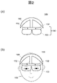
- FIG. (a) and (b) are explanatory diagrams for explaining a processing outline of the first embodiment.
- (a) and (b) are explanatory diagrams for explaining an external view of the head-mounted display (HMD) of the first embodiment and how it is mounted, respectively.
- HMD head-mounted display
- It is a HMD hardware block diagram of 1st embodiment.
- 2 is a functional block diagram of the HMD of the first embodiment;
- FIG. (a), (b), and (c) are explanatory diagrams for explaining an example of the behavioral state data, the electroencephalogram for verification, and the abnormal information, respectively, according to the first embodiment.
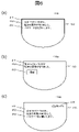
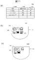
- (a) and (b) are explanatory diagrams for explaining a display example of the first embodiment and a display example of the modification, respectively, and (c) is a display example of the modification of the third embodiment. It is an explanatory view for explaining. It is a flow chart of analysis evaluation processing of a first embodiment. It is a flowchart of the analysis evaluation process of the modification of 1st embodiment. (a) and (b) are respectively explanatory diagrams for explaining usage modes of different modifications of the first embodiment. It is a functional block diagram of HMD of a second embodiment. (a) is an explanatory diagram for explaining an instruction setting example of the second embodiment, and (b) and (c) are explanatory diagrams for explaining display examples of the second embodiment.
- FIG. 11 is an explanatory diagram for explaining transmission and reception of signals between the HMD and the server in the modified example of the second embodiment; It is a functional block diagram of HMD of a third embodiment.
- (a) and (b) are explanatory diagrams for explaining an example of a support application database and an output example, respectively, according to the third embodiment.
- (a) to (c) are explanatory diagrams for explaining the appearance of a smartphone that is a modified example of the embodiment of the present invention.
- an HMD Head Mounted Display
- a function of measuring and analyzing brain waves is provided with a function of measuring and analyzing brain waves. Then, when dementia is suspected, when the user's consciousness is clear, it is notified that dementia is suspected, prompts the user for early examination and treatment, contributes to early detection of dementia, etc. As a result, it delays the progression of the disease.
- an HMD 100 with a function of measuring brain waves is used. Then, the HMD 100 detects the behavior of the wearer (user) 109, determines whether the wearer 109 is awake (awakening) or asleep (sleeping), detects the electroencephalogram of the wearer 109, and determines whether an abnormality is suspected. Determine whether or not there is
- the brain waves of a healthy adult and the brain waves of an adult with dementia are stored in advance. Then, by comparing with the detected electroencephalogram, it is determined whether or not there is an abnormality (suspected dementia).
- suspected anomaly is simply referred to as “there is an anomaly (there is an anomaly)”.
- no suspicion of abnormality it is referred to as “no abnormality (no abnormality)”.
- dementia will be described as an example of an abnormality to be detected.
- the disease (case) to which the present embodiment can be applied is not limited to dementia, as long as the electroencephalogram has an "abnormal” state and an "abnormal” state.
- the HMD 100 determines that "abnormality exists"
- it is temporarily recorded.
- the HMD 100 determines that the wearer 109 is awake and notifies the wearer 109 that there is an abnormality at the timing when it determines that there is no abnormality.
- the HMD 100 may further give a stimulus to the wearer 109 (light movement, asking a question) to make the determination more accurate.
- the presence or absence of an abnormality in the wearer 109 is determined using electroencephalograms, and the wearer 109 is notified at the timing when it is determined that there is no abnormality. That is, for example, when the degree of dementia of the wearer 109 is low, the HMD 100 of this embodiment notifies the wearer 109 that dementia is suspected and prompts the wearer 109 to go to the hospital. As a result, for example, an abnormality occurring in the brain such as dementia can be detected early, and the wearer 109 can be made aware of it.
- the HMD 100 of this embodiment that implements this will be described below.
- FIG. 2(a) is an external view of the HMD 100
- FIG. 2(b) is a diagram showing the HMD 100 worn by the wearer 109. As shown in FIG.
- the HMD 100 includes a body portion 180 and a support portion 190 that supports the body portion 180 .
- the main unit 180 includes, for example, the display 133, the in-camera 131, the out-camera 132, and a configuration (information processing unit) that implements the information processing function.
- a hardware configuration of the main unit 180 will be described later.
- the support part 190 is coupled to the body part 180 and engages the head of the wearer 109 to support the body part 180 . As shown in FIG. 2B, the main body part 180 is supported on the head of the wearer 109 by the support part 190 .
- the support part 190 is, for example, a hair band type as shown in this figure.
- the support part 190 may have, for example, a band shape extending so as to surround the side and rear surfaces of the head of the wearer 109 .
- a plurality of electrodes are arranged on the head of the wearer 109, and electroencephalograms are acquired from potential differences. These multiple electrodes are arranged on the body portion 180 and/or the support portion 190 . The arrangement position is determined according to the electroencephalogram acquisition method. Details will be described later.
- Electrodes for example, commonly used plate electrodes and disk electrodes are used. Silver, silver chloride, or the like is used as the material of the electrodes. A silicone-based conductive rubber may also be used.
- FIG. 3 is a hardware configuration diagram of the main unit 180 of this embodiment.
- a main body 180 of the HMD 100 includes a main processor 101, a system bus 102, a storage device 110, an input interface (I/F) 120, an image processing device 130, and an audio processing device 140. , a sensor 150 and a communication interface (I/F) 160 .
- the main processor 101 is a main control unit that controls the entire HMD 100 according to a predetermined program.
- the main processor 101 is realized by a CPU (Central Processor Unit) or a microprocessor unit (MPU).
- the main processor 101 performs processing according to a clock signal measured and output by a timer included in the HMD 100 .
- the main processor 101 controls each part of the HMD 100 by, for example, reading an operating system (OS) stored in the storage device 110 and various application programs for operation control into the work area of the RAM 111 and executing them. Together, it implements the OS and each function.
- OS operating system
- the system bus 102 is a data communication path for transmitting and receiving data between the main processor 101 and each section within the main body section 180 of the HMD 100 .
- the storage device 110 stores data necessary for processing by the main processor 101, data generated by the processing, and the like.
- the storage device 110 includes a RAM (Random Access Memory) 111 , a ROM (Read Only Memory) 112 and a flash memory 113 .
- the RAM 111 is a program area for executing basic operation programs and other application programs. Also, the RAM 111 is a temporary storage area that temporarily holds data as necessary when various application programs are executed. The RAM 111 may be integrated with the main processor 101 .
- the ROM 112 and the flash memory 113 store each operation setting value of the HMD 100, information of the user of the HMD 100 (wearer 109), and the like. These may store still image data, moving image data, or the like captured by the HMD 100 . Also, the HMD 100 can be expanded in function by downloading a new application program from the application server via the Internet. At this time, the downloaded new application program is stored in them. The HMD 100 can realize various functions by the main processor 101 expanding the new application programs stored therein into the RAM 111 and executing them. Devices such as SSDs (Solid State Drives) and HDDs (Hard Disc Drives) may be used instead of these.
- SSDs Solid State Drives
- HDDs Hard Disc Drives
- Each function of the information processing unit (computer), which will be described later, is also realized by the main processor 101 developing the programs stored in the ROM 112 and the flash memory 113 into the RAM 111 and executing them.
- the input I/F 120 accepts input to the HMD 100.
- the input I/F 120 has, for example, a button switch 121 and an electroencephalogram detection device 122 .
- operation keys such as a power key, a volume key, and a home key may be provided.
- a touch sensor that receives an operation instruction from a touch pad may be provided. The touch sensor is arranged as a touch panel so as to overlap the display 133, which will be described later.
- operations to the HMD 100 may be accepted via a separate information processing terminal device connected by wired communication or wireless communication.
- the electroencephalogram detection device 122 receives the electroencephalograms acquired by the electrodes.
- the image processing device 130 includes an image (video) processor, an in-camera 131 , an out-camera 132 and a display 133 .
- Each of the in-camera 131 and the out-camera 132 captures an image of the surrounding visual field, and acquires an image by converting the light incident from the lens into an electrical signal with an imaging device.
- the number of in-cameras 131 and out-cameras 132 does not matter.
- the out-camera 132 acquires images around the HMD 100 .
- the out-camera 132 is provided on the surface (front surface) of the body portion 180 opposite to the screen of the display 133 . As shown in FIG. 2( a ), the out-camera 132 is arranged, for example, above the display 133 of the main body 180 facing outward.
- the in-camera 131 photographs the face or eyes of the wearer 109 looking at the screen, and imports the image into the HMD 100 .
- the in-camera 131 also functions as a line-of-sight detection sensor.
- the in-camera 131 is arranged facing inward (facing the wearer 109 side), for example, above the display 133 of the main body 180 .
- the in-camera 131 is provided on the same surface of the main unit 180 as the screen of the display 133 .
- the in-camera 131 may be placed at any position, but is placed at a position where the eyeball can be photographed in order to detect the line-of-sight direction of the wearer 109 as described above.
- the in-camera 131 also detects opening and closing of the eyes of the wearer 109 .
- the images acquired by the in-camera 131 and the out-camera 132 are processed by the image (video) signal processor or main processor 101 , superimposed with objects generated by the main processor 101 and the like, and output to the display 133 .
- the display 133 is a display device using, for example, a laser, a liquid crystal panel, or an organic EL (EL: Emitting Diode).
- the image data processed by the image processor is presented to the wearer 109 of the HMD 100 by projecting it onto the retina of the wearer 109 .
- the display 133 displays notification information to the wearer 109 such as warning information and instruction information, application icons, various status display images, and the like within the screen.
- the display 133 is arranged in front of both eyes of the wearer 109, as shown in FIG. 2(b).
- the display 133 may be of an optical see-through type or a video see-through type.
- the optical transmission type has a half-mirror, and the surroundings (actual scene) can be seen through the display screen.
- the video transmissive type the actual scene cannot be seen, but the surroundings photographed by the out-camera 132 are displayed on the display screen, and the wearer 109 can grasp the outside by looking at the image.
- a touch panel may be laminated on the screen of the display 133 .
- the touch panel is composed of, for example, a capacitive touch panel member, and the wearer 109 can input information that the wearer 109 wants to input by approaching or contacting with a finger or a touch pen (hereinafter referred to as touch).
- a touch panel is an example of an operation input member.
- the operation input member is, for example, a keyboard or key buttons connected for communication via the communication I/F 160, or a voice input device in which the wearer 109 utters a voice indicating an input operation, collects the sound with the microphone 142, and converts it into operation information. , or a gesture input device that captures and analyzes gestures of the wearer 109 .
- the audio processing device 140 includes an audio signal processor that processes audio, and includes a speaker 141 that is an audio output unit and a microphone 142 that is an audio input unit.
- Two speakers 141 are provided, for example, and are arranged near the right ear and left ear of the wearer 109 of the support section 190, respectively.
- the microphone 142 is arranged, for example, at the tip of a microphone support extending from the support 190 .
- the speaker 141 outputs various output information (including notification information and instruction information) in the HMD 100 to the outside by voice. Also, the microphone 142 collects sounds from the outside and the voice of the wearer 109 himself/herself, converts them into sound signals, and takes them into the HMD 100 .
- the HMD 100 can take in operation information in the form of vocalizations from the wearer 109, and can conveniently execute operations in response to the operation information.
- a sensor 150 is a sensor group for detecting the state of the HMD 100 .
- the sensor 150 includes, for example, a GPS (Global Positioning System) receiver 151, a geomagnetic sensor 152, a distance sensor 153, an acceleration sensor 154, a gyro sensor 155, and a biological information acquisition sensor 156. Note that the sensor 150 is not limited to these. Moreover, it is not necessary to have all of these.
- the HMD 100 detects the position, movement, tilt, direction, etc. of the HMD 100 using these sensors.
- each sensor 150 does not matter.
- the distance sensor 153 is arranged in front of the HMD 100 and detects the distance from the HMD 100 to the object.
- the communication I/F 160 is a communication processor that performs communication processing.
- Communication I/F 160 includes wireless communication I/F 161 and telephone network communication I/F 162 .
- the wireless communication I/F 161 is an interface for wireless communication, and performs LAN (Local Area Network) communication, short-range wireless communication, and the like. In the case of LAN communication, data is transmitted and received by connecting to a wireless communication access point on the Internet by wireless communication.
- the telephone network communication I/F 162 performs telephone communication (phone call) and data transmission/reception by wireless communication with a base station of the mobile telephone communication network.
- the wireless communication I/F 161 and the telephone network communication I/F 162 each include an encoding circuit, a decoding circuit, an antenna, and the like. A communication I/F according to other standards may be provided.
- Examples of short-range wireless communication include Bluetooth (registered trademark), IrDA (Infrared Data Association, registered trademark), Zigbee (registered trademark), HomeRF (Home Radio Frequency, registered trademark), or Wi-Fi (registered trademark) standards. There is a compliant communication, etc. Communication using an electronic tag, for example, may also be used.
- the telephone network communication I/F 162 may use long-distance wireless communication such as W-CDMA (Wideband Code Division Multiple Access, registered trademark) and GSM (Global System for Mobile Communications). Although not shown, the communication I/F 160 may use other methods such as optical communication and sound wave communication as means for wireless communication.
- W-CDMA Wideband Code Division Multiple Access, registered trademark
- GSM Global System for Mobile Communications
- the HMD 100 has a timer 173 as a clock for the main processor 101.
- an (LED) lamp 171 may be provided to call the attention of the wearer 109 .
- you may provide expansion I/F172.
- the extension I/F 172 is a group of interfaces for extending the functions of the HMD 100, and in this embodiment, includes a charging terminal, video/audio interface, USB (Universal Serial Bus) interface, memory interface, and the like.
- the video/audio interface inputs video/audio signals from an external video/audio output device, outputs video/audio signals to an external video/audio input device, and the like.
- the USB interface connects USB devices.
- a memory interface connects a memory card or other memory medium to transmit and receive data.
- a vibrator that emits vibration under the control of the main processor 101 may be provided.
- the vibrator converts the notification information sent from the HMD 100 to the wearer 109 into vibration.
- FIG. 3 includes many configurations that are not essential to the present embodiment, the effects of the present embodiment are not impaired even if these are not provided.
- FIG. 4 is a functional block diagram of the functions associated with this embodiment of HMD 100.
- the HMD 100 includes an input/output processing section 210 and an analysis processing section 220 .
- the input/output processing unit 210 includes a sensor processing unit 211, an electroencephalogram processing unit 212, an output processing unit 213, and an input processing unit 214.
- the analysis processing unit 220 includes a behavior analysis unit (behavior analysis means) 221 and , an electroencephalogram determination unit (electroencephalogram determination means) 222 and a control unit (control means) 223 .
- Each unit is connected by a bus 201 and can transmit and receive data to and from each other.
- the HMD 100 also includes a storage unit 230 that stores various data used for processing by the analysis processing unit 220 or obtained as a result of processing.
- the storage unit 230 stores analysis data 231 , behavioral state data 232 , electroencephalograms for comparison 233 , abnormality presence information 234 , and confirmation test data 235 .
- the storage unit 230 is built in the storage device 110 .
- the sensor processing unit 211 processes signals detected by various sensors of the sensor 150 and shooting signals input from the in-camera 131 and the out-camera 132 .
- the sensor processing unit 211 puts these signals into a state (behavior data) that can be processed by the behavior analysis unit 221 and outputs the signals to the behavior analysis unit 221 . Further, it outputs a sensor signal to the control unit 223 as necessary.
- the sensor 150 and the sensor processing unit 211 constitute a behavior measuring unit (behavior measuring device).
- the sensor processing unit 211 analyzes images acquired by the in-camera 131 and the out-camera 132, receives gesture input by the wearer 109, and determines the intention of the wearer 109 based on signals detected by the sensor 150. It also performs general input interface processing of the HMD 100 such as
- the electroencephalogram processing unit 212 puts the electroencephalograms detected by the electroencephalogram detection device 122 into a state (electroencephalogram data) that can be processed by the electroencephalogram determination unit 222 and outputs the electroencephalograms to the electroencephalogram determination unit 222 .
- the electrodes, the electroencephalogram detection device 122, and the electroencephalogram processing unit 212 constitute an electroencephalogram measurement unit (electroencephalogram measurement device).
- the electroencephalogram processing unit 212 also outputs electroencephalogram data to the control unit 223 as necessary.
- the output processing unit 213 outputs the processing result of the analysis processing unit 220 to the output device.
- the output is made to the display 133, the speaker 141, the lamp 171, and the like.
- the input processing unit 214 processes data input via the input I/F 120 .
- pressing of the button switch 121 is detected.
- a processing result is output to the analysis processing unit 220 .
- the behavior analysis unit 221 performs behavior analysis for analyzing whether the wearer 109 is awake (hereinafter referred to as “waking”) or not (hereinafter referred to as “sleeping”) based on the behavior data received from the sensor processing unit 211. process.
- the behavior analysis unit 221 analyzes the state of the wearer 109 using signals from the various sensors 150 and prestored analysis data 231 .
- the behavior analysis unit 221 identifies the posture, movement state, eye opening/closing, etc. of the wearer 109 based on sensor signals, and determines whether the wearer 109 is awake or sleeping based on the identification results.
- the behavior analysis unit 221 outputs the analysis result as an analysis result signal to the electroencephalogram determination unit 222 and stores it in the storage unit 230 as behavior state data 232 in association with the analysis time.
- the behavior analysis unit 221 receives behavior data at predetermined time intervals and performs behavior analysis.
- the time interval is, for example, in units of several minutes.
- FIG. 5(a) An example of the action state data 232 is shown in FIG. 5(a).
- the behavior analysis unit 221 receives behavior data every 10 minutes and performs behavior analysis processing.
- the analysis result state 232b is registered in association with the behavior analysis start time (time 232a).
- the behavior analysis is performed from 8:00 to 16:00, the person is sleeping from 10:00 to just before 10:20, and is awake during the rest of the period.
- the posture of the wearer 109 is determined, for example, from the surrounding image acquired by the out-camera 132 and the outputs of the acceleration sensor 154, gyro sensor 155, and the like. For example, when the output from the acceleration sensor 154 or the gyro sensor 155 does not show a predetermined change or more for a predetermined period of time, it is determined that the person is sleeping. If these outputs indicate a standing or sitting state, it is determined that the subject is awake. If the body is lying down, it is determined that it is sleeping.
- the state of motion of the wearer 109 is determined, for example, from an image of the surroundings acquired by the out-camera 132 and outputs from the acceleration sensor 154, the gyro sensor 155, and the like.
- the opening and closing of the eyes is determined by analyzing an image of the eyes of the wearer 109 acquired by the in-camera 131 . If the analysis result shows that the eyes are open, it is determined that the subject is awake, and if the analysis results indicate that the eyes are closed, it is determined that the subject is sleeping. Various criteria are stored in the analysis data 231 .
- the behavior analysis unit 221 may further subdivide and determine the behavior state of the wearer 109 in addition to whether the wearer 109 is awake or sleeping.
- the subdivision is, for example, whether it is in a resting state or in other states during wakefulness.
- Other states include, for example, moving states such as walking and running, eating states, and the like.
- the electroencephalogram determination unit 222 determines whether or not there is an abnormality in the electroencephalogram of the wearer 109 based on the electroencephalogram data processed by the electroencephalogram processing unit 212 and the analysis result received from the behavior analysis unit 221 . In this embodiment, the electroencephalogram determining unit 222 determines whether or not the electroencephalogram of the wearer 109 is suspected of dementia. The electroencephalogram determination section 222 outputs the determination result to the control section 223 as a determination result signal. In addition, the electroencephalogram determination unit 222 records the abnormality presence information 234 in the storage unit 230 when determining “abnormal”.
- the electroencephalogram determination unit 222 determines whether there is an abnormality by comparing the received electroencephalogram data with the electroencephalogram for comparison 233 stored in the storage unit 230 in advance.
- FIG. 5(b) An example of the electroencephalogram for verification 233 stored in the storage unit 230 is shown in FIG. 5(b).
- the state of electroencephalograms differs depending on the behavioral state (during wakefulness and during sleep).
- an electroencephalogram 233b in a normal state and an electroencephalogram 233c in an abnormal state are stored according to the behavioral state 233a.
- normal (healthy) electroencephalogram data and demented electroencephalogram data are stored as electroencephalograms 233 for reference during wakefulness and during sleep.
- the electroencephalogram determination unit 222 determines the result of normality or dementia, whichever has a higher degree of matching with the acquired electroencephalogram data.
- each electroencephalogram data stored as the electroencephalogram 233 for verification is selected in advance from general case data etc. and stored according to the attribute information of the wearer 109 . Attribute information is, for example, age, sex, and the like. Further, the selected electroencephalogram data may be stored in consideration of pre-existing diseases and the like.
- each action state in wakefulness for example, a resting state, a moving state, a eating state, etc.
- the normal state is determined according to each state.
- the electroencephalogram 233b and the electroencephalogram 233c in the abnormal state are stored as the electroencephalogram 233 for reference.
- the control unit 223 performs predetermined processing.
- a determination result signal indicating that there is an abnormality is received from the electroencephalogram determination section 222
- data (abnormality presence information 234 ) indicating “abnormality” is recorded in the storage section 230 .
- control unit 223 determines whether or not there is abnormality information 234 in the storage unit 230. Then, when there is the abnormality presence information 234 , output information is generated and transmitted to the output processing unit 213 . Also, the control unit 223 deletes the unnotified abnormality existence information 234 .
- the abnormality presence information may be recorded in the storage unit 230 in association with the time, and a notified flag may be set when the output information is generated.
- the control unit 223 receives the determination result signal indicating "no abnormality", it determines whether or not there is unnotified abnormality information. Then, when there is unnotified abnormality existence information, output information is generated.
- a determination result 234b indicating "abnormal" is recorded in association with time 234a. Furthermore, a notification column 234c is also provided to indicate whether or not notification has been completed. By recording in association with the time and recording whether or not the notification has been completed, it is possible to leave a record of determination as "abnormal".
- the output information transmitted by the control unit 223 is, for example, a message to be displayed on the display 133. Also, it is audio data output from the speaker 141 . Alternatively, it may be a lighting signal for the lamp 171 .
- control unit 223 may perform confirmation processing before the record is notified.
- the confirmation process is performed for the purpose of performing a predetermined inspection (confirmation inspection) and confirming whether the wearer 109 has certainly grasped the notification.
- control unit 223 causes the wearer 109 to perform a predetermined operation as a confirmation test.
- the operation to be executed includes, for example, inputting a password, operating a predetermined operation unit, making a gesture, answering a predetermined question, performing calculation, identifying an image, and the like.
- Control unit 223 causes one or more of these combinations to be executed.
- the execution instruction and the model answer are stored in the storage unit 230 in advance as confirmation test data 235 .
- the control unit 223 causes the output processing unit 213 to output an execution instruction, and receives the operation of the wearer 109 via the input processing unit 214 or the sensor processing unit 211 as an answer.
- the method of presenting an execution instruction and inputting an answer any method that is possible with the HMD 100 may be used.
- a password input screen is displayed on the display 133 to prompt the wearer 109 to input.
- Input is detected in the line-of-sight direction of the wearer 109 . For example, this is done by determining whether or not each key has been designated for the line-of-sight direction of the wearer 109 .
- the button switch 121 is used for input.
- the password may be uttered by voice and detected by the microphone 142 .
- a VR (Virtual Reality) keyboard may be displayed and the touch of the wearer 109 may be detected by image analysis and the distance sensor 153 .
- image identification for example, images of vegetables, fruits, animals, etc. are displayed and the name is entered.
- name input is performed by displaying a keyboard for line-of-sight input, voice input, or virtual input.
- the calculation problem is displayed on the display 133, and the answer is input from the keyboard displayed on the display 133 by visual input, voice input, or virtual input.
- a light stimulus may be applied to determine whether the brain responds.
- an image for reaction confirmation such as a lamp, which repeats display and non-display of the entire image or part of the image displayed on the display unit at regular intervals. For example, a bright image, characters, or the like are displayed, the displayed image is repeatedly displayed and hidden, and the lamp 171 is turned on and off. It is determined whether or not a specific change occurs in the electroencephalogram at the timing of these light stimulations.
- the electroencephalograms detected by the electroencephalogram detection device 122 are processed by the electroencephalogram processing unit 212 and checked by the control unit 223 .
- the control unit 223 determines that the wearer 109 is in a state where the wearer 109 can grasp the notification and that the notice has been transmitted to the wearer 109, and performs processing to erase the abnormality presence information. On the other hand, if the correct answer is not accepted, the notification process is performed again.
- FIG. 6(a) shows a display example 410 on the display 133 when the output is display.
- the output processing unit 213 displays the time 411 when the electroencephalogram abnormality was detected, the message 412, and the message 414 for confirmation examination.
- message 414 for confirmation check is an example of prompting for password input.
- the input processing unit 214 notifies the control unit 223 when receiving the input of the password by the wearer 109 .
- the control unit 223 determines whether the entered password is appropriate, and deletes the abnormality presence information 234 if it is appropriate.
- the output processing unit 213 When outputting by voice, the output processing unit 213 generates a voice message and outputs it from the speaker 141 . Further, the wearer 109 may be notified by blinking or lighting the lamp 171 . Also, if the HMD 100 has a vibration function, it may be vibrated. Also, a message prompting to go to the hospital may be added.
- Electroencephalogram acquisition methods include, for example, referential recording, bipolar recording, average potential reference electrode, and source derivation.
- the reference electrode derivation method (unipolar lead method) is a method of acquiring (recording) the potential difference between two points between the probe electrode on the scalp and the reference electrode placed on the earlobe as an electroencephalogram. It is easy to grasp the potential distribution of the whole brain, and it is generally used for determination of the fundamental wave and execution of the activation method.
- the bipolar derivation method is a method that records the potential difference between two probe electrodes on the scalp, and is suitable for searching for the focus of localized abnormal waves.
- the average reference electrode method is a method of recording electroencephalograms based on the average value of the potential when a predetermined resistance is applied to each electrode on the scalp. Although the absolute value at each electrode is unknown, the relative difference to detect the state of the distribution.
- the source derivation method is a method of recording electroencephalograms based on the weighted average potential of the electrodes surrounding the lead-out electrode. detectable.
- Electrodes are placed on the support portion 190 or the body portion 180 depending on the technique used. For example, in the case of the reference electrode derivation method, electrodes are placed on the parts corresponding to the earlobe and the forehead. The electrode placed on the earlobe is used as the reference electrode.
- FIG. 7 is a processing flow of the analysis evaluation processing of this embodiment.
- the HMD 100 executes the following analysis evaluation process at predetermined time intervals.
- the predetermined time interval is, for example, an interval of several minutes.
- the behavior analysis unit 221 performs behavior analysis processing for analyzing the state of the wearer 109 based on the sensor signal processed by the sensor processing unit 211 (step S1101).
- the behavior analysis unit 221 identifies whether the wearer 109 is awake or sleeping.
- the behavior analysis section 221 outputs the analysis result to the electroencephalogram determination section 222 .
- the analysis result is recorded in the storage unit 230 as the action state data 232 in association with the time.
- the electroencephalogram determination unit 222 acquires an electroencephalogram for a predetermined period (electroencephalogram determination period) and compares it with the electroencephalogram for comparison 233 (step S1102).
- the electroencephalogram determination unit 222 identifies electroencephalogram data with the highest degree of matching among the electroencephalograms for comparison 233, and determines whether there is an abnormality in the electroencephalogram of the wearer 109 (step S1103). That is, when the electroencephalogram data in normal state has the highest degree of agreement, it is determined as normal, and when the electroencephalogram data in dementia has the highest degree of agreement, it is determined as dementia (with abnormality).
- the electroencephalogram determination unit 222 uses the analysis result of the behavior analysis unit 221 . Also, the electroencephalogram determination section 222 outputs a determination result signal indicating the determination result to the control section 223 .
- the control unit 223 records the abnormality information 234 in the storage unit 230 (step S1104).
- the control unit 223 determines whether or not the abnormal information 234 is recorded in the storage unit 230 (step S1105). If it is not recorded, the process is terminated.
- the control unit 223 determines whether the abnormality information 234 is recorded. If the abnormality information 234 is recorded, the control unit 223 generates output information and performs abnormality notification processing for notifying the wearer 109 that there is an abnormality (step S1106). Then, the control unit 223 executes confirmation inspection (step S1107).
- the control unit 223 repeats the abnormality presence notification process and the confirmation inspection until the correct answer for the confirmation inspection is obtained (step S1108).
- the control unit 223 determines that the correct answer has been obtained, for example, when a valid input operation is performed within a predetermined period of time.
- control unit 223 deletes the information indicating that there is an abnormality (step S1109), and terminates the process.
- the HMD 100 of the present embodiment includes an electroencephalogram measurement device (the electroencephalogram detection device 122 and the electroencephalogram processing unit 212) that outputs electroencephalogram data of the wearer 109 who is a user, and an action data of the wearer 109.
- electroencephalogram data Based on the behavior measurement device (sensor 150, in-camera 131, out-camera 132, and sensor processing unit 211), electroencephalogram data and behavior data, it is determined whether there is an abnormality in the electroencephalogram data. and a control unit 223 that performs predetermined support processing for the wearer 109 .
- the HMD 100 of this embodiment further includes a behavior analysis unit 221 that determines whether or not the wearer 109 is awake based on behavior data, and a storage unit 230.
- the control unit 223 performs determination. If the result is “abnormality present”, the abnormality presence information 234 is stored in the storage unit 230 . Then, when the determination result is “no abnormality” and the determination result by the behavior analysis unit 221 is that the storage unit 230 stores information indicating that there is an abnormality, the control unit 223 causes the wearer 109 to receive an electroencephalogram. An error notification is sent to indicate that there is an error. The control unit 223 erases the abnormality information 234 after notifying the abnormality.
- the HMD 100 of the present embodiment has the above-described configuration, and when the wearer's 109 electroencephalogram shows a symptom suspecting the occurrence of an abnormality such as dementia, the wearer 109 himself/herself is notified of this in a normal state.
- a dementia state and a normal state alternate.
- the HMD 100 of the present embodiment detects a state of dementia by analyzing electroencephalograms, dementia is suspected in a normal state (when the suspicion of dementia is low and the wearer 109 is highly conscious). This is notified to the wearer 109 himself. This can help the wearer 109 to become aware of an abnormality such as dementia at an early stage. At this time, you may be encouraged to go to the hospital.
- the wearer 109 can be encouraged to undergo early examination and treatment, and the wearer 109 is more likely to go to the hospital early for diagnosis and treatment. As a result, it is possible to prevent symptoms from progressing without the person's awareness, and to delay the progress of diseases such as dementia as much as possible.
- the notification can be made in a state in which the wearer 109 can reliably make a normal judgment.
- the control unit 223 performs confirmation inspection after notifying the wearer 109 that there is an abnormality, but confirmation inspection is not essential. That is, when the electroencephalogram determination unit 222 determines that there is an abnormality, the control unit 223 notifies the wearer 109 that there is an abnormality without a confirmation test at the timing when it determines that there is an abnormality. It is also possible to simply accept the operation of A display example 410a on the display 133 in this case is shown in FIG.
- the output processing unit 213 displays the time 411 when the electroencephalogram abnormality was detected and the message 412 . Further, the output processing unit 213 displays a confirmation button display 413 and the like. This is displayed to ensure that the wearer 109 has received the message. Note that the input processing unit 214 notifies the control unit 223 upon receiving an instruction from the wearer 109 . After receiving the notification that the confirmation button display 413 has been instructed, the control unit 223 deletes the abnormality presence information 234 .
- confirmation button display 413 may be omitted.
- control unit 223 performs the abnormality notification process and then performs the confirmation inspection, but the order may be reversed. For example, as shown in FIG. 8, when the presence of abnormality is recorded in step S1105, the control unit 223 first performs a confirmation inspection (step S1107). Then, when a correct answer is accepted (step S1108), the control unit 223 notifies that there is an abnormality (step S1106).
- the electroencephalogram data for verification registers a general waveform, but is not limited to this.
- the normal electroencephalogram waveform of the wearer 109 may be acquired in advance and registered.
- the electroencephalogram determination unit 222 may analyze the shape of the electroencephalogram data to determine the presence or absence of an abnormality, instead of comparing it with the data itself registered in advance. That is, the electroencephalogram determination unit 222 determines that dementia is suspected when electroencephalogram data specific to an abnormal state (dementia in this embodiment) is obtained. For example, when the wearer 109 is awake and a slow wave (such as a delta wave with a long wavelength) appears, it is determined that dementia is suspected.
- a slow wave such as a delta wave with a long wavelength
- the HMD 100 may be configured to notify a predetermined contact address immediately after detecting an impact to the wearer 109 if an abnormality occurs.
- the behavior analysis unit 221 not only analyzes whether the person is awake or sleeps, but also notifies the electroencephalogram determination unit 222 when a large impact is detected.
- the electroencephalogram determination unit 222 transmits an abnormality occurrence signal to the control unit 223 when determining that “abnormality exists” immediately after the impact is detected, or when the electroencephalogram is in a predetermined state.
- the electroencephalogram state in which an abnormality occurrence signal should be transmitted is, for example, detected by analyzing the signal acquired by the biometric information acquisition sensor 156, in which an amplitude greater than a predetermined threshold occurs in the electroencephalogram before the impact is detected. It is an abnormality that occurred.
- the control unit 223 When the control unit 223 receives the abnormality occurrence signal, it notifies a predetermined notification destination.
- the report destinations are, for example, relatives registered in advance in the storage unit 230, the police, hospitals, security companies, and the like. The report is made by, for example, sending an e-mail to these report destination addresses via the communication I/F 160 .
- reporting is not limited to cases of shock.
- the control unit 223 may record that fact and report it to the outside.
- the destination of the report is, for example, preset relatives, guardians, guardians, hospitals, insurance companies, and the like.
- the control unit 223 may notify the outside.
- the report destinations are preset relatives, guardians, hospitals, guardians, insurance companies, etc., as described above.
- the HMD 100 may be of a separate type in which the display 133 and each functional unit realized by the main processor 101 are separated.
- the display 133 has only a display control function and a wireless or wired communication I/F, and transmits and receives signals and data through communication with each functional unit.
- each functional unit may be realized by an external device such as a smart phone 360 or a mobile terminal device.
- the display 133 transmits and receives signals and data to and from each functional unit within the mobile terminal via the wireless communication I/F.
- a wired cable may be used.
- each functional unit may be realized by a PC (Personal Computer).
- an external device that implements some functions may be a server 320 connected via a network 310, as shown in FIG. 9(b).
- the HMD 100 outputs the acquired sensor data and electroencephalogram data to an external device (server 320) via the wireless communication I/F 161.
- Wireless communication I/F 161 connects to network 310 via wireless router 330 .
- the HMD 100 When the HMD 100 acquires the sensor signal used to determine the state of the wearer 109, it transmits it to the server 320 via the wireless communication I/F 161. In addition, when the HMD 100 acquires electroencephalogram data, the HMD 100 transmits the data to the server 320 via the wireless communication I/F 161 .
- the server 320 side manages sensor signals and electroencephalogram data for each transmission source. These signals and data are managed, for example, in storage 340 accessible by server 320 .
- the server 320 performs the above-described analysis evaluation process for each transmission source at predetermined time intervals, and notifies the transmission source of the analysis result.
- the server 320 performs the functions of the behavior analysis unit 221 and the electroencephalogram determination unit 222 , and the HMD 100 performs the functions of the control unit 223 .
- the server 320 determines the presence or absence of an electroencephalogram abnormality at predetermined time intervals, and notifies the HMD 100 of the determination result for each determination.
- the HMD 100 records the abnormality information 234 in the storage unit 230 when the determination result is "abnormal", and then notifies the wearer 109 when the determination result is "abnormal".
- the server 320 may perform all the functions of the analysis processing unit 220 .
- the server 320 transmits output information to the HMD 100 .
- the output processing unit 213 performs output for notifying the wearer 109 of "abnormality" at that timing.
- the output information received from the server 320 may be, for example, the message itself notifying of an abnormality in the electroencephalogram or a signal indicating the presence of an abnormality. In the latter case, the HMD 100 side generates and outputs a predetermined message.
- the matching electroencephalogram 233 used on the server 320 side is not limited to storage for each state (wakeful, sleeping). For example, they may be classified and stored according to attribute information such as age, sex, and pre-existing diseases.
- the attribute information of the wearer 109 is registered in the server 320 in advance, and the server 320 determines the electroencephalogram 233 to be used for verification based on the registered information at the time of determination.
- the normal brain wave data of the wearer 109 may be registered in the server 320 as the reference brain wave 233 .
- each function provided in the HMD 100 of the present embodiment is independent.
- a user support system that is implemented by a device that performs the same processing as the HMD 100 of the present embodiment as a whole may be configured.
- the presence or absence of abnormality in the electroencephalogram of the wearer 109 is determined at predetermined time intervals, but the timing of determination of the presence or absence of abnormality is not limited to this.
- batch processing may be performed, and the presence or absence of abnormality may be determined after collecting data for one day. Then, when there is a period of "abnormal", the abnormal information is recorded. Then, the notification process is performed at the timing when the wearer 109 wears the HMD 100 on the next day. In this case, since the notification is not always given in the normal state, the confirmation inspection or the display of the "Confirm" button is always performed.
- the HMD 100 determines that the wearer 109 is not in a state where he/she can make a normal judgment when there is an abnormality in the brain wave, and prevents the wearer 109 from operating functions that are assumed to require restrictions.
- the icons of finance-related and shopping-related applications, such as settlement are not displayed on the menu screen.
- restrict functions such as payment by individual settings of the application.
- the appearance and hardware configuration of the HMD 100 of this embodiment are the same as those of the first embodiment. Also, the functional configuration of this embodiment is the same as that of the first embodiment. However, in this embodiment, the processing of the control unit 223 is different. Further, as shown in FIG. 10, an instruction setting 236 to be described later is stored in the storage unit 230 in advance for the processing of the control unit 223 .
- the control unit 223 When the electroencephalogram determination unit 222 determines that "abnormality exists", the control unit 223 records information about the presence of abnormality, as in the first embodiment. Further, the control unit 223 performs processing (application setting processing) for restricting the operation of the application. Note that in the application setting process, when the electroencephalogram determination unit 222 determines that there is no abnormality, a process of canceling the restrictions that were set when it was determined that there was an abnormality is performed.
- a control signal (restriction signal) is output to various applications installed in the HMD 100.
- the control unit 223 outputs, for example, a start stop signal for stopping the start and a setting change signal for changing the setting of the application to each application according to the instruction setting 236 .
- an example of the instruction setting 236 is shown in FIG. 11(a).
- an abnormality limit 236b indicating whether or not a limit is required when there is an abnormality, and whether or not the application is compatible (presence/absence) are indicated.
- Application support 236c is registered.
- control unit 223 when "necessary" is registered in the abnormality restriction 236b and "no" is registered in the application support 236c, the application needs to be restricted, but the application side performs the restriction. Decide that you are not ready. Then, the control unit 223 directly outputs an activation stop signal to stop the activation of the application.
- control unit 223 determines that the application needs to be restricted. It is determined that there is Then, the control unit 223 outputs a setting change signal to the application.
- control unit 223 determines that the application does not need to be limited, and does not output a limit signal to the application.
- control unit 223 when it is determined that "abnormality exists", the control unit 223 outputs a start/stop signal for the XX bank application, and outputs a setting change signal for the ⁇ shopping application. On the other hand, no limiting signal is output for the XX event.
- the application that has received the activation stop signal will not be activated even if the wearer 109 issues an activation instruction. Note that the application that has received the start/stop signal may stop displaying the icon on the menu display.
- the application that receives the setting change signal locks the predetermined functions so that they cannot be used. For example, in a ⁇ shopping application, the payment function is locked. As a result, the wearer 109 can activate this application and view (browse) products, but cannot make payments.
- a normal menu display example 420 and a menu display example 420a when it is determined to be "abnormal" (abnormal) are shown in FIGS. 11(b) and 11(c), respectively.
- the icon 421 of the application of OO bank receiving the start/stop signal is displayed in the normal menu display example 420, but is not displayed in the abnormal display example 420a.
- the icon 422 of the ⁇ shopping application receiving the setting change signal is displayed in both the menu display examples 420 and 420a.
- the restricted functions are, for example, payment functions. In other words, it is possible to browse commodities using the ⁇ shopping application, but not to make payments.
- the icon 423 of the XX paint application that has not received the activation stop signal or the setting change signal is displayed in both the menu display examples 420 and 420a. Also, all functions can be executed as they are.
- control unit 223 records the application that has transmitted the start/stop signal and the control instruction signal. Then, when it is determined to be normal, an abnormality is notified and these settings are canceled. Specifically, an activation/termination release signal is transmitted to an application that has transmitted an activation/termination signal, and a control termination signal is transmitted to an application that has transmitted a control instruction signal.
- the activation/suspension release signal is a signal that releases the suspension of the application whose activation has been temporarily suspended, and the control release signal is a signal that releases the suspension of the function that has been suspended by the control instruction. Both signals are collectively called a release signal.
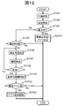
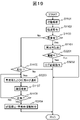
- FIG. 12 shows the flow of the analysis evaluation process of this embodiment. This process is performed at predetermined time intervals as in the first embodiment. Hereinafter, processing different from the first embodiment will be mainly described.
- control unit 223 when it is determined that there is an abnormality, not only records the abnormality information 234, but also sends a restriction signal to each application installed in the HMD 100 according to the instruction setting 236.
- An application setting process for transmission is performed (step S2101), and the process ends.
- the control unit 223 first determines whether or not the abnormality information 234 is recorded. Then, when the abnormality presence information 234 is recorded, as in the first embodiment, the control unit 223 repeats the abnormality presence notification process and the confirmation inspection until a correct answer is obtained in the confirmation inspection. When the correct answer is obtained, the control unit 223 deletes the information indicating that there is an abnormality (step S1109) and determines whether or not there is an application for which application setting processing has been performed (step S2102), as in the first embodiment. If there is such an application, the setting of that application is canceled by transmitting a cancellation signal (step S2103), and the processing ends. If there is no corresponding application, the process is terminated as it is.
- the HMD 100 of the present embodiment outputs an instruction to restrict processing to a predetermined application when the determination result of the electroencephalogram determination unit 222 is "abnormal".
- the wearer 109 not only is the wearer 109 notified, but also the functions of the HMD 100 are restricted. As a result, it is possible to reduce the possibility that the wearer 109 performs unintended processing in a state where an abnormality is occurring in the electroencephalogram.
- the instruction setting 236 is registered in advance for each application, and the control unit 223 outputs a restriction signal to the corresponding application according to the registered contents.
- the control unit 223 may determine necessity from the attribute information of each application and output a necessary restriction signal. For example, if there is a setting in the properties of the application, the control unit 223 uses that setting.
- the control unit 223 performs recording and notification of the abnormality information 234 according to the processing flow of FIG. 7 and the like, as in the first embodiment.
- the application setting process is performed when an instruction to display a menu or an instruction to start an application is received. If the abnormality presence information 234 is recorded, the control unit 223 refers to the instruction setting 236 and performs the application setting process for the corresponding application. Also, when the abnormality existence information 234 is deleted, it is determined whether or not there is an application for which application settings have been made, and if there is a corresponding application, the settings are canceled.
- control unit 223 transmits control signals such as a start/stop signal, a control instruction signal, a start/stop release signal, and a control release signal to all the synchronized devices.
- control unit 223 when the HMD 100 is synchronized with the smart phone 360 and the smart watch 370, the control unit 223 also outputs the control signals to these devices via the communication I/F 160. do.
- Communication with the smartphone 360 and smartwatch 370 may be short-range wireless communication such as Bluetooth, or Wi-Fi communication via a wireless router.
- External devices to be synchronized are registered in the HMD 100 in advance.
- the configuration may be such that the guardian can release the restriction.
- authentication information such as the guardian's ID and password is registered in the external device in advance.
- the guardian inputs the authentication information to the external device.
- the external device cancels the restriction according to the instruction from the HMD 100 when the authentication is successful based on the authentication information. Note that each external device may be put into a restricted state again if it is not operated for a certain period of time after the restriction is released.
- the function may be restricted by transmitting a signal to the server that provides the service of the application. That is, instead of transmitting a restriction signal such as a start/stop signal or a setting instruction signal to the application in the HMD 100, a signal requesting restriction to the server that provides the service of the application (restriction request signal). signal).
- a restriction signal such as a start/stop signal or a setting instruction signal
- a signal requesting restriction to the server that provides the service of the application (restriction request signal). signal).
- control unit 223 has the function of monitoring the processing of a predetermined application, and when the monitored application performs the predetermined processing, the control unit 223 transmits a restriction request signal to the server that provides the service of the application. do.
- a monitoring target process 237d is registered in place of the application correspondence 236c with respect to the instruction setting 236 described above.
- control unit 223 executes the process registered in the monitoring target process 236d of the application for which "required" is registered in the abnormal time limit 236b in the instruction setting 236. Monitor.
- the control unit 223 transmits a restriction request signal to the service provider server.
- the control unit 223 records the server that has transmitted the restriction request signal.
- the control unit 223 transmits a restriction cancellation request signal to the recorded server.
- the restriction release request signal is a request to release the restriction.
- a specific example will be described below for this modified example.
- the case where the wearer 109 uses the ⁇ shopping application will be described as an example.
- a shopping server 380 serving as a service provider of this application and a settlement server 390 are connected to the HMD 100 via the network 310 .
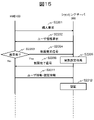
- FIG. 15 is a diagram for explaining the flow of processing in this modified example.
- the ⁇ shopping application installed in the HMD 100 is hereinafter referred to as a shopping application.
- the shopping application transmits a purchase request to the shopping server 380 (step S2201).
- the shopping server 380 transmits a user information request to the source HMD 100 (step S2202).
- control unit 223 When the control unit 223 detects that the monitoring target process has been performed in the monitoring target application, it first determines whether or not the abnormality presence information 234 is recorded (step S2203).
- the control unit 223 transmits a restriction request signal to the shopping server 380 (step S2204). At this time, the shopping application records that the restriction request signal has been sent.
- the restriction setting process is a process of notifying the settlement server 390 not to accept a settlement request from the requester while imposing a predetermined restriction on access from the requester.
- the restriction is, for example, not accepting a purchase confirmation request from the requesting HMD 100 .
- the shopping server 380 After completing the restriction setting process, the shopping server 380 transmits a restriction completion signal to the shopping application (step S2206).
- the shopping application that has received the restriction completion signal continues normal shopping processing.
- user information and authentication information are transmitted to the shopping server 380 (step S2211), and authentication is received (step S2212).
- step S2205 the processing restricted in step S2205 cannot be executed. For example, it is not possible to confirm a purchase and proceed to payment.
- the shopping application continues normal shopping processing in steps S2211 and S2212.
- control unit 223 transmits a restriction release request to the server that has a record of transmitting the restriction request signal.
- the transmission of the restriction release request is not limited to this timing. For example, later, when wearer 109 submits a monitored transaction (eg, purchase request) via the same shopping app on HMD 100 . In this case, the control unit 223 transmits a restriction release request signal for requesting release of the restriction when there is a record of transmission of the restriction request signal without registration of abnormality information.
- a monitored transaction eg, purchase request
- the control unit 223 transmits a restriction release request signal for requesting release of the restriction when there is a record of transmission of the restriction request signal without registration of abnormality information.
- the restriction release process is a process of notifying the settlement server 390 of the fact as well as releasing the restriction on the access from the request source.
- the shopping site can perform appropriate restrictions. Payments can also be restricted.
- the shopping application may transmit the user information of the wearer 109 before the control unit 223 transmits the restriction request signal.
- the shopping server 380 side may determine the type of restriction and whether payment is possible based on the user information.
- the shopping server 380 may perform a confirmation test on the wearer 109 of the HMD 100 that is the source of the request.
- the confirmatory inspection is the same as the confirmatory inspection of the first embodiment.
- the shopping server 380 transmits the question to the requesting HMD 100. Then, it waits for a response from the HMD 100 .
- Control unit 223 displays the transmitted question on the display and accepts an answer within a predetermined time. Then, when the answer is received within the predetermined time, the control unit 223 transmits the received answer to the shopping server 380 . On the other hand, if no reply has been received within the predetermined time, the control unit 223 notifies the shopping server 380 of the fact that the reply has not been received.
- the shopping server 380 determines the correctness of the received responses, including those with no response. If the answer is correct, the limit setting process is not performed. Otherwise, the limit setting process is performed.
- various modifications of the first embodiment can be applied, except for the modification in which the presence or absence of an abnormality is determined by batch processing. Conversely, in the present embodiment, when it is determined that there is an abnormality, it is not necessary to notify the wearer 109 that there is an abnormality.
- the wearer 109 may not be able to determine the action, and activates the support application.
- the support application to be activated is determined in advance according to the behavior of the wearer 109 at that time.
- a route guidance application is activated as a support application.
- the HMD 100 issues guidance, such as a direction indication, even on a road or the like that normally does not require guidance.
- the wearer can more easily notice that the guide is being issued by using voice.
- the appearance and hardware configuration of the HMD 100 of this embodiment are the same as those of the first embodiment. Also, the functional configuration of this embodiment is the same as that of the first embodiment. However, in this embodiment, the processing of the behavior analysis unit 221 and the control unit 223 are different. Further, as shown in FIG. 16 , a support application database (DB) 237 , which will be described later, is stored in advance in the storage unit 230 for the processing of the control unit 223 .
- DB support application database
- the behavior analysis unit 221 identifies not only whether the wearer 109 is awake or sleeping, but also the current position of the wearer 109 when the wearer 109 is awake.
- the current position to be identified is whether the user is outside the home (while going out), whether the user is at home, and if the user is at home, which room the user is in.
- the identification result is output to the control section 223 .
- the current position is specified based on the signal obtained from the GPS receiver 151, for example. Whether the wearer 109 is out or at home is specified based on the home address of the wearer 109 .
- the control unit 223 When the electroencephalogram determination unit 222 determines that "abnormality exists", the control unit 223 records the abnormality information 234 as in the first embodiment. Furthermore, the control unit 223 performs a process of transmitting a start signal (application start process) to a predetermined support application. Note that, in the application activation process, when the electroencephalogram determination unit 222 determines that there is no abnormality, a process of stopping the support application that was activated when the determination was that there was an abnormality may be performed.
- the support application to be activated in the application activation process is predetermined according to the current position of the wearer 109. Therefore, in this embodiment, the support application DB 237 is provided in which support applications to be activated are registered according to the current position of the wearer 109 .
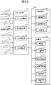
- FIG. 17(a) an example of the support application DB 237 is shown in FIG. 17(a).
- a support application 237b to be activated is registered for each current position 237a of the wearer 109.
- FIG. Further, detailed settings 237c to be set for the support application to be activated are registered as necessary.
- a support application to be registered is an application installed in the HMD 100 and an application that supports actions of the wearer 109 .
- the route guidance application is registered as the support application 237b to be activated, and home is registered as the destination as the detailed setting 237c.
- different settings may be made according to the distance between the current position and the home. For example, set different target values. Specifically, if the current position is a predetermined distance or more from home, a nearby public institution such as a police box may be set as the destination.
- the home appliance control application is registered as the support application 237b to be activated. Then, detailed setting 237c is registered, such as controlling to turn off the IH cooking heater when the current position is the kitchen, and turning off the TV after one hour when the current position is the living room.
- the route guidance application will be activated.
- a display example on the display 133 and an output sound example to the speaker 141 in this case are shown in FIG.
- the route guidance application supports the wearer 109 by, for example, displaying the direction of travel in AR. Furthermore, in the example of this figure, the activated route guidance application not only provides route guidance by display, but also uses voice to assist the wearer 109 .
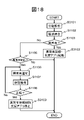
- FIG. 18 shows the flow of the analysis evaluation process of this embodiment. This process is performed at predetermined time intervals as in the first embodiment. The following description focuses on processing different from the first embodiment.
- the behavior analysis unit 221 also acquires the current location information of the wearer 109 in the behavior analysis (step S3101).
- control unit 223 not only records the abnormality information 234, but also activates the support application defined in the support application DB 237 (step S3102), and ends the process. At this time, the control unit 223 uses information on the current position of the wearer 109 specified by the behavior analysis unit 221 . At this time, the parameters registered in the detailed setting 237c are set as necessary.
- the control unit 223 determines whether or not the abnormality information 234 is recorded, as in the first embodiment. Then, when the abnormality information 234 is recorded, the control unit 223 first repeats the notification of abnormality and the confirmation inspection until a correct answer is obtained in the confirmation inspection (steps S1106, S1107, S1108). Then, if a correct answer is obtained in the confirmation test, the abnormality presence information 234 is deleted, the activated support application is stopped (step S3103), and the process is terminated. If the support application has not been activated, the abnormality presence information 234 is deleted, and the process is terminated.
- the control unit 223 activates a predetermined support application according to the current position of the wearer 109. .
- the HMD 100 activates the support application.
- an action log recording application for recording an action log may be activated.
- the behavior log may be recorded only during wakefulness, for example.
- control unit 223 determines whether or not the person is awake after recording the abnormality information 234 (step S3201). If the subject is awake, control unit 223 outputs an instruction to record an action log (step S3202). For example, an activation instruction is issued to an application that records an action log. Even if it is not one application, for example, a sound recording application, a moving image shooting application, an operation recording application, a shooting application, etc., a plurality of predetermined applications capable of obtaining an action log are instructed to start and to start operation. may Note that if the subject is not awake, the process ends without recording the action log.
- control unit 223 not only informs that there is an abnormality but also the action log in the abnormality presence notification process (step S3203). At this time, the control unit 223 does not need to notify all action logs, and may notify only a predetermined action log. Also, instead of notifying the action log itself, it is possible to notify that the action log is being recorded.
- a display example 410b on the display 133 in this case is shown as a display example 410b in FIG. 6(c).
- a message indicating that there is an action log, an icon 415, and the like are displayed.
- the control unit 223 may be configured to display the action log.
- control unit 223 performs a confirmation test (step S1107), and if the correct answer is accepted, deletes the abnormality presence information 234, stops log recording (step S3204), and ends the process.
- the recorded action log is video, audio, movement route, etc., including time.
- An action log recording application may be installed in advance, and all necessary information may be recorded simply by starting the application.
- the video may be recorded by activating the out-camera 132 .
- Audio may be recorded by activating the microphone 142 .
- the moving route may be recorded by associating the current position information received by the GPS receiver 151 with time.
- Audio recordings may be, for example, not only conversations, but also voice calls.
- the recording may be recorded as voice or may be saved as text.
- an application for converting voice to text is installed and the application is also started.
- the other party's face image is acquired by the out-camera 132. If an image recognition/matching application is installed, the face area of the face image may be analyzed to identify the partner. Identification is performed within the range of pre-registered persons.
- the operation record of the button switch 121 may be held as an action log. Further, the output of the acceleration sensor 154 or the like may be processed, and when the HMD 100 is subjected to a predetermined impact or more, the time, the strength of the impact, and the like may be recorded. Furthermore, instead of storing all the recorded video, when there is an impact of a predetermined level or more, the video may be stored for a predetermined period before and after the impact.
- the electroencephalogram determination unit 222 determines that there is an "abnormality"
- the action log of the wearer 109 during that period is collected and notified in the normal state.
- the wearer 109 can grasp his or her behavior while the electroencephalogram state is not normal.
- the action log to be recorded may be changed according to the current position of the wearer 109.
- the behavior analysis in step S3101 is performed to specify the current position of the wearer 109.
- a support application registered in the support application DB 237 may be activated.
- each modification of the first embodiment is applicable, except for the modification in which the presence or absence of an abnormality is determined by batch processing.
- this embodiment may be combined with the second embodiment. Furthermore, in this embodiment as well, when it is determined that there is an abnormality, it is not necessary to notify the wearer 109 that there is an abnormality.
- the brain wave abnormality is dementia
- the factors that cause electroencephalogram abnormalities are not limited to dementia.
- the electroencephalogram may be determined only when an abnormality occurs in the electroencephalogram.
- An example of an abnormality in memory function is drinking.
- the electroencephalogram shows a waveform state similar to that of Alzheimer's dementia.
- this embodiment will be described by taking drinking as an example of a factor. That is, in the HMD 100 of this embodiment, when it is determined that the wearer 109 has drunk alcohol, the presence or absence of brain wave abnormality is determined at predetermined time intervals, as in each of the above embodiments. Then, when it is determined that there is an abnormality, the behavior after that is recorded. Then, the action is notified when the wearer 109 is normal.
- the action record may be an action log or a video record.
- the appearance and hardware configuration of the HMD 100 of this embodiment are the same as those of the first embodiment. Also, the functional configuration of this embodiment is the same as that of the first embodiment. However, in this embodiment, the function of each part is different.
- the behavior analysis unit 221 determines not only whether the wearer 109 is awake or asleep, but also whether the wearer 109 has drunk. Then, when it is determined that there is drinking, a record of having drinking is recorded.
- the behavior analysis unit 221 determines whether or not the person is drinking alcohol, for example, by analyzing the image acquired by the out-camera 132 . Specifically, when it is detected from the camera image of the wearer 109 that the wearer 109 is drinking alcohol (bottle, can, container: glass, mug, sake cup, etc.), it is determined that the wearer 109 is drinking alcohol.
- an alcohol detection sensor may be further provided as the sensor 150, and determination may be made based on the output of the sensor. Alternatively, the determination may be made based on the schedule of the wearer 109 (setting of welcome party, New Year's party, drinking party, etc.) registered in the HMD 100 .
- the wearer 109 may be configured to report drinking.
- the control unit 223 When the wearer 109 declares, the control unit 223 generates, for example, an input screen and displays it on the display 133 . Then, a report from the wearer 109 is accepted.
- the electroencephalogram determination unit 222 of the present embodiment Upon receiving notification from the action analysis unit 221 that the wearer 109 has drunk, the electroencephalogram determination unit 222 of the present embodiment starts determining whether or not there is an abnormality in the electroencephalogram.
- the electroencephalogram determination unit 222 performs determination at predetermined time intervals, as in the above embodiments.
- control unit 223 When it is determined that "abnormality exists", the control unit 223 records the abnormality information 234 and instructs to start recording an action log.
- the recorded contents are, for example, the same as those of the modified example of the third embodiment.
- the behavior analysis unit 221 detects the presence or absence of drinking at predetermined time intervals (step S4101).
- the electroencephalogram determination unit 222 checks electroencephalograms at predetermined time intervals (steps S4102, S1102).
- the control unit 223 records the abnormality information 234 (step S1104) and outputs an instruction to the relevant application and various functions to record an action log. (step S4103).
- the details are the same as those of the modification of the third embodiment. After that, the HMD 100 returns to step S4102 and repeats from the determination process.
- step S1103 determines whether or not the abnormality presence information 234 is recorded (step S4111).
- the control unit 223 waits for a predetermined period to elapse from the timing when it is determined that "abnormality is not present” (step S4112). This is because the action log is recorded for a certain period of time when the "abnormal” state changes to the "abnormal” state.
- control unit 223 After the predetermined period has elapsed, the control unit 223 notifies the wearer 109 of the abnormality information 234 and the recorded action log. This is repeated until a correct answer is obtained in the confirmation test (steps S4113, S1107, S1108). After that, the control unit 223 stops recording the action log, deletes the abnormality information (step S4114), and returns to step S4101.
- the electroencephalogram determination unit 222 starts electroencephalogram determination when the wearer 109 performs a predetermined action such as drinking alcohol. Then, when it is determined that there is an abnormality, the wearer 109 is notified of the normal state. In addition, the HMD 100 of the present embodiment records an action log of the wearer 109 and notifies the wearer 109 when it is determined that there is an abnormality.
- the HMD 100 of the present embodiment can: The abnormality can be appropriately detected and necessary measures can be taken. That is, according to this embodiment, when the wearer 109 drinks alcohol and an abnormality similar to memory impairment occurs in the electroencephalogram, an action log is automatically recorded. Then, the action log can be checked in the normal state. Therefore, the wearer 109 can grasp his or her own behavior during the memory impairment period, and can take appropriate measures as necessary.
- the action log is recorded for a certain period of time even when the determination "abnormal” changes to "abnormal". Therefore, even if no abnormality is found in the electroencephalogram, an action log in which the sense of the wearer 109 is ambiguous is also recorded.
- ⁇ Modification 12> Note that if the presence or absence of drinking is determined based on the report from the wearer 109, the above processing is started after step S4101 when the report from the wearer 109 is received.
- modifications other than each modification of the first embodiment, in which the determination of the presence or absence of an abnormality is performed by batch processing, can be applied.
- brain waves are detected in the head.
- brain wave detection is not limited to this.
- techniques for reading electroencephalograms from the skin surface of arms and hands such as BodyWave Technology, have been developed.
- brain waves may be detected by a wearable terminal such as a smart watch, a smartphone, or the like, which implements this technology.
- Figures 21(a) and 21(b) show an example of a smartphone 610 implementing the above technology.
- FIG. 21( a ) is an example in which bipolar electroencephalogram measurement electrodes 631 and 632 are arranged on the back surface 620 of the smartphone 610 .
- FIG. 21B shows an example in which bipolar electroencephalogram measurement electrodes 631 and 632 are arranged on both sides 640 and 650 of the smart phone 610, respectively.
- the induction method is bipolar induction, and electroencephalograms are measured from the potential difference derived from two electrodes.
- the electrodes 631 and 632 are arranged on the back surface 620 or both side surfaces 640 and 650 where they are easily touched.
- the back surface 620 is the surface opposite to the surface (front surface) on which the display is arranged.
- all the electrodes shown in FIGS. 21(a) and 21(b) may be mounted, or they may be mixed.
- one location on the rear surface 620 and one location on one of the side surfaces 640 and 650, or one location on the back surface 620 and two locations on the side surfaces 640 and 650 may be mixed.
- an electrode that can detect potential in a non-contact state may be used.
- An example of electrode arrangement in this case is shown in FIG.
- the electrodes 631 and 632 are arranged, for example, on the front face 660 of the smart phone 610 on both sides of the speaker 672 above the display 671 .
- contactless electrodes for body area networks have been developed. This is an example of electrode placement using this technique.
- the electroencephalogram potential of the user can be derived. Since the electrodes are non-contact, there is no need to bring the electrodes into contact with the head.
- Each electrode 631, 632 is equipped with an amplifier, an ADC, and a communication module, and can transmit the derived potential from one electrode to the other electrode. These electrodes 631 and 632 can derive a potential even if there is an insulator between the electrodes 631 and 632 and the head.
- ⁇ Modification 14> when the abnormality to be detected is dementia, information other than electroencephalograms may be used for determination. For example, determination is made using the facial expression of the wearer 109 (user). In particular, eye expressions and movements are used. For example, it is determined whether the state of the brain is normal or abnormal based on how the eyes of the wearer 109 track the target when the target displayed on the display unit (display) is moved. A target is, for example, a pointer, an icon, or the like. Also, the tracking status of the eyes of the wearer 109 is determined by analyzing the image of the eyes of the wearer 109 acquired by the in-camera 131 . Any analysis method may be used.
- the display of the target is performed periodically, for example, when awakening.
- the display of the target object may be started after the wearer 109 remains stationary such as sitting down for a certain period of time.
- the target may blink or be notified by sound.
- the maximum value of the amount of motion when acquiring electroencephalogram data is recorded in a predetermined measurement unit.
- the behavior analysis unit 221 may be configured to refer to the maximum value and determine that determination is not possible when the detected movement of the wearer 109 is equal to or greater than the maximum value.
- the HMD 100, the smartphone 610, the smart watch, and the like have been described as examples. Applicable to terminals.
- the present invention is not limited to the above-described embodiments, and includes various modifications.
- the above-described embodiments have been described in detail in order to explain the present invention in an easy-to-understand manner, and are not necessarily limited to those having all the configurations described.
- part of the configuration of one embodiment can be replaced with the configuration of another embodiment, and the configuration of another embodiment can be added to the configuration of one embodiment.
- each of the configurations, functions, processing units, processing means, etc. described above may be implemented in hardware, for example, by designing them in integrated circuits, in part or in whole.
- each of the above configurations, functions, etc. may be realized by software by a processor interpreting and executing a program for realizing each function.
- Information such as programs, tables, and files that implement each function may be stored in recording devices such as memory, hard disks, SSDs (Solid State Drives), or recording media such as IC cards, SD cards, and DVDs. and may be stored in a device on a communication network.
- control lines and information lines indicate what is considered necessary for explanation, and not all control lines and information lines are necessarily indicated on the product. In practice, it may be considered that almost all configurations are interconnected.
Landscapes
- Health & Medical Sciences (AREA)
- Life Sciences & Earth Sciences (AREA)
- Engineering & Computer Science (AREA)
- General Health & Medical Sciences (AREA)
- Biomedical Technology (AREA)
- Heart & Thoracic Surgery (AREA)
- Public Health (AREA)
- Medical Informatics (AREA)
- Biophysics (AREA)
- Physics & Mathematics (AREA)
- Pathology (AREA)
- Molecular Biology (AREA)
- Surgery (AREA)
- Animal Behavior & Ethology (AREA)
- Veterinary Medicine (AREA)
- Business, Economics & Management (AREA)
- Psychology (AREA)
- Psychiatry (AREA)
- Physiology (AREA)
- General Business, Economics & Management (AREA)
- Gerontology & Geriatric Medicine (AREA)
- Physical Education & Sports Medicine (AREA)
- Emergency Management (AREA)
- General Physics & Mathematics (AREA)
- Primary Health Care (AREA)
- Epidemiology (AREA)
- Pulmonology (AREA)
- Anesthesiology (AREA)
- Cardiology (AREA)
- Hospice & Palliative Care (AREA)
- Social Psychology (AREA)
- Educational Technology (AREA)
- Developmental Disabilities (AREA)
- Child & Adolescent Psychology (AREA)
- Measurement And Recording Of Electrical Phenomena And Electrical Characteristics Of The Living Body (AREA)
- Measurement Of The Respiration, Hearing Ability, Form, And Blood Characteristics Of Living Organisms (AREA)
Abstract
Description
本発明の第一実施形態を説明する。まず、本実施形態の概要を、図1(a)および図1(b)を用いて説明する。
図2(a)および図2(b)を用いて、本実施形態のHMD100の外観を説明する。図2(a)は、HMD100の外観図であり、図2(b)は、HMD100を装着者109が装着した状態を示す図である。
次に,HMD100の本体部180のハードウェア構成を説明する。図3は、本実施形態の本体部180のハードウェア構成図である。本図に示すように、HMD100の本体部180は、メインプロセッサ101と、システムバス102と、記憶装置110と、入力インタフェース(I/F)120と、画像処理装置130と、音声処理装置140と、センサ150と、通信インタフェース(I/F)160と、を備える。
次に、HMD100の情報処理部の、本実施形態に関連する機能構成について説明する。図4は、HMD100の本実施形態に関連する機能の、機能ブロック図である。本図に示すように、HMD100は、入出力処理部210と、分析処理部220と、を備える。入出力処理部210は、センサ処理部211と、脳波処理部212と、出力処理部213と、入力処理部214と、を備える、分析処理部220は、行動解析部(行動解析手段)221と、脳波判定部(脳波判定手段)222と、制御部(制御手段)223と、を備える。各部はバス201で接続され、相互にデータの送受信が可能である。
ここで、出力処理部213による出力例を説明する。出力処理部213は、制御部223から出力情報を受け取ると、出力情報に応じて対応する出力装置から、異常があることを通知する異常通知を出力する。
次に、脳波取得手法について、簡単に説明する。脳波の取得法には、例えば、基準電極導出法(referential recording)、双極導出法(bipolar recording)、平均基準電極法(average potential reference electrode)、発生源導出法(source derivation)等がある。
以下、本実施形態のHMD100による分析評価処理の流れを説明する。図7は、本実施形態の分析評価処理の処理フローである。例えば、HMD100は、以下の分析評価処理を、所定の時間間隔で実行する。所定の時間間隔は、例えば、数分間隔等である。
なお、上記実施形態では、制御部223は、装着者109に異常が有る事を通知後、確認検査を行っているが、確認検査は必須ではない。すなわち、脳波判定部222により「異常有」と判定された場合、制御部223は、「異常無」と判定されたタイミングで、確認検査無しに異常があることを通知し、装着者109から確認の操作を受け付けるだけでもよい。この場合のディスプレイ133への表示例410aを、図6(b)に示す。
また、上記実施形態では、制御部223は、異常有通知処理を行い、その後、確認検査を行っているが、順序は逆であってもよい。例えば、図8に示すように、制御部223は、ステップS1105において、異常有が記録されている場合、まず、確認検査を行う(ステップS1107)。そして、正解を受け付けた場合(ステップS1108)、制御部223は、異常有通知を行う(ステップS1106)。
また、上記実施形態では、照合用の脳波データは、一般的な波形を登録しているが、これに限定されない。例えば、正常時の脳波波形は、予め、装着者109の正常時の脳波波形を取得し、登録してもよい。
また、HMD100は、衝撃を検知した直後に、装着者109に、異常が生じた場合、予め定めた連絡先に通報するよう構成してもよい。
なお、HMD100は、ディスプレイ133と、メインプロセッサ101が実現する各機能部とが分離した、分離型であってもよい。この場合、ディスプレイ133は、表示制御機能と無線または有線の通信I/Fのみを備え、各機能部と通信により信号、データの送受信を行う。
また、上記実施形態や変形例では、所定の時間間隔で、装着者109の脳波の異常の有無を判定しているが、異常の有無の判定タイミングは、これに限定されない。例えば、バッチ処理とし、一日のデータを収集後、異常の有無を判定してもよい。そして、「異常有」の期間がある場合、異常有情報を、記録する。そして、翌日、装着者109がHMD100を装着したタイミングで通知処理を行う。この場合は、必ずしも正常時に通知がなされるとは限らないので、必ず、確認検査、または、「確認」ボタンの表示を行う。
次に、本発明の第二実施形態について説明する。第一実施形態では、脳波の異常、例えば、認知症の疑いがある場合、それを、装着者109本人に通知する。本実施形態では、脳波の異常が発見された場合、HMD100に搭載されている所定のアプリケーションプログラム(以下、単にアプリケーションと呼ぶ。)に制限をかける。
本実施形態の分析評価処理の流れを、図12に示す。本処理は、第一実施形態同様、所定の時間間隔で行われる。以下、第一実施形態と異なる処理について主眼をおいて説明する。
なお、上記実施形態では、予め、各アプリケーションについて、指示設定236を登録し、登録内容に従って、制御部223が対応するアプリケーションに対して制限信号を出力する。しかしながら、予め指示設定236を登録せず、制御部223が各アプリケーションの属性情報等から要否を判定し、必要な制限信号を出力するようにしてもよい。制御部223は、例えば、アプリケーションのプロパティに設定があれば、その設定を使用する。
なお、本実施形態において、異常判定がなされた場合、すぐに、アプリケーション設定処理を行っているが、この手法に限定されない。異常有情報234の記録とアプリ設定処理とは独立して行ってもよい。
さらに、HMD100を他の外部機器と同期させている場合、アプリケーションの設定も、同期させてもよい。1以上の外部機器と同期している場合、制御部223は、起動停止信号、制御指示信号、起動停止解除信号、制御解除信号等の制御信号を、同期している全ての機器に送信する。
HMD100本体で、アプリケーションの機能を制限するのではなく、当該アプリケーションのサービス提供元のサーバに信号を送信し、機能を制限してもよい。すなわち、HMD100内のアプリケーションに対して、起動停止信号や設定指示信号等の制限信号を送信するのではなく、当該アプリケーションのサービスを提供する提供元のサーバに対して制限を要求する信号(制限要求信号)を送信する。
次に、本実施形態の第三実施形態を説明する。本実施形態では、装着者109の脳波に「異常有」と判定された場合、装着者109の行動を支援するアプリケーションプログラム(支援アプリケーションプログラム。以下、単に支援アプリケーションと呼ぶ。)を自動的に起動させる。
本実施形態の分析評価処理の流れを、図18に示す。本処理は、第一実施形態同様、所定の時間間隔で行われる。以下、第一実施形態と異なる処理に主眼をおいて説明する。
また、上記実施形態では、脳波判定部222が「異常有」と判定した場合、HMD100は、支援アプリケーションを起動させる。ここで、支援アプリケーションとして、行動ログを記録する行動ログ記録するアプリケーションを起動させてもよい。行動ログは、例えば、覚醒中の場合のみ記録してもよい。
なお、上記各実施形態および変形例では、脳波の異常が認知症の場合を例にあげて説明した。しかしながら、脳波の異常が発生する要因は、認知症に限定されない。例えば、脳波に異常が発生する要因が生じた場合のみ、脳波の判定を行うよう構成してもよい。
なお、飲酒の有無を、装着者109からの申告で判断する場合は、装着者109からの申告があったことを契機に、上記処理をステップS4101の後から開始する。
なお、上記各実施形態および変形例では、脳波を頭部で検出している。しかしながら、脳波の検出は、これに限定されない。近年、脳波を腕や手の皮膚表面から読み取る技術例えばBodyWave Technologyが開発されている。この技術を実装した、例えば、スマートウォッチ等のウェアラブル端末や、スマートフォン等で脳波を検出してもよい。
さらに、検出対象の異常が、認知症である場合、脳波以外の情報で判定してもよい。例えば、装着者109(ユーザ)の表情等を用いて判定する。特に、目の表情や動きが用いられる。例えば、表示部(ディスプレイ)に表示した目標物を移動させた時の、装着者109の目の、目標物に対する追尾状況により、脳の状態が正常か異常かを判定する。目標物は、例えば、ポインタやアイコン等である。また、装着者109の目の追尾状況は、インカメラ131で取得した装着者109の目の画像を解析することにより、判断する。解析手法は問わない。
なお、上記各実施形態および変形例において、覚醒中の行動状態には、正確な脳波の計測が難しい状態がある。そのため、計測対象者がある一定以上の動き中は脳波を計測しない等の対応がとられることがある。この場合、照合用脳波233の脳波233b、233cは、計測対象者の動きが所定の範囲内で取得されたものである。
201:バス、210:入出力処理部、211:センサ処理部、212:脳波処理部、213:出力処理部、214:入力処理部、220:分析処理部、221:行動解析部、222:脳波判定部、223:制御部、230:記憶部、231:解析用データ、232:行動状態データ、232a:時刻、232b:状態、233:照合用脳波、233a:状態、233b:正常状態の脳波、233c:異常状態の脳波、234:異常有情報、234a:時刻、234b:判定結果、234c:通知欄、235:確認検査データ、236:指示設定、236a:名称、236b:異常時制限、236c:アプリ対応、236d:監視対象処理、237:支援アプリDB、237a:現在位置、237b:支援アプリケーション、237c:詳細設定、237d:監視対象処理、
310:ネットワーク、320:サーバ、330:無線ルータ、340:記憶装置、360:スマートフォン、370:スマートウォッチ、380:ショッピングサーバ、390:決済サーバ、
412:メッセージ、413:確認ボタン表示、414:メッセージ、415:アイコン、421:アイコン、422:アイコン、423:アイコン、610:スマートフォン、620:背面、631:脳波測定用電極、632:脳波測定用電極、640:側面、650:側面、660:前面、671:ディスプレイ、672:スピーカ
Claims (12)
- ユーザの脳波データを出力する脳波測定装置と、
前記ユーザの行動データを出力する行動測定装置と、
前記脳波データと前記行動データとに基づいて前記脳波データの異常の有無の判定を行う脳波判定装置と、
前記判定の結果が異常有りの場合、予め定めた処理を行う制御装置と、を備えること
を特徴とするユーザ支援システム。 - 請求項1記載のユーザ支援システムであって、
前記行動データに基づいて、前記ユーザが覚醒中であるか否かの判別を行う行動解析装置と、
記憶装置と、をさらに備え、
前記制御装置は、
前記判定の結果が異常有りの場合、異常有りを示す異常有情報を前記記憶装置に記憶し、
前記記憶装置に前記異常有情報が記憶されている場合、前記判別の結果が前記覚醒中を示し、かつ、前記判定の結果が異常無しの期間に、前記脳波データに異常があることを意味する異常通知を行い、前記異常有情報の消去を行うこと
を特徴とするユーザ支援システム。 - 請求項2記載のユーザ支援システムであって、
前記制御装置は、前記異常通知の後、前記消去の前に、予め定めた確認検査を実行し、前記ユーザから正解の応答があるまで、前記異常通知と前記確認検査とを繰り返すこと
を特徴とするユーザ支援システム。 - 請求項1記載のユーザ支援システムであって、
前記制御装置は、前記判定の結果が異常有りの場合、予め定めたアプリケーションプログラムに対し、処理を制限する制限信号を送信すること
を特徴とするユーザ支援システム。 - 請求項4記載のユーザ支援システムであって、
通信インタフェースをさらに備え、
前記制御装置は、前記通信インタフェースを介して予め定めた外部機器に対し、前記制限信号を送信すること
を特徴とするユーザ支援システム。 - 請求項1記載のユーザ支援システムであって、
通信インタフェースをさらに備え、
前記制御装置は、前記判定の結果が異常有りの場合、予め定めたアプリケーションプログラムのサービス提供元のサーバに対し、前記通信インタフェースを介して、処理の制限を要求する制限要求信号を送信すること
を特徴とするユーザ支援システム。 - 請求項1記載のユーザ支援システムであって、
前記制御装置は、前記判定の結果が異常有りの場合、予め定めた支援アプリケーションプログラムに対し、起動信号を送信すること
を特徴とするユーザ支援システム。 - 請求項1記載のユーザ支援システムであって、
前記制御装置は、前記判定の結果が異常有りの場合、ユーザの行動ログを収集すること
を特徴とするユーザ支援システム。 - 請求項1記載のユーザ支援システムであって、
前記脳波判定装置は、前記行動データに基づいて、前記ユーザが予め定めた行為を行った場合、前記判定を開始すること
を特徴とするユーザ支援システム。 - ユーザの脳波データを出力する脳波測定部と、
ユーザの行動データを出力する行動測定部と、
前記脳波データと前記行動データとに基づいて前記脳波データの異常の有無の判定を行う脳波判定部と、
前記判定の結果が異常有りの場合、予め定めた処理を行う制御部と、を備えること
を特徴とするウェアラブル端末。 - ユーザの脳波データを出力する脳波測定部と、
前記ユーザの行動データを出力する行動測定部と、
前記脳波データと前記行動データとを用いて処理を行う情報処理部と、を備えるウェアラブル端末におけるユーザ支援方法であって、
前記脳波データと前記行動データとに基づいて前記脳波データの異常の有無の判定を行い、
前記判定の結果が異常有りの場合、予め定めた処理を行うこと
を特徴とするユーザ支援方法。 - コンピュータを、
ユーザの脳波データと、前記ユーザの行動データとに基づいて、前記脳波データの異常の有無の判定を行う脳波判定手段、
前記脳波判定手段による前記判定の結果が異常有りの場合、予め定めた処理を行う制御手段、として機能させるためのプログラム。
Priority Applications (4)
| Application Number | Priority Date | Filing Date | Title |
|---|---|---|---|
| PCT/JP2021/022692 WO2022264263A1 (ja) | 2021-06-15 | 2021-06-15 | ユーザ支援システム、ウェアラブル端末、ユーザ支援方法およびプログラム |
| US18/570,581 US20240277281A1 (en) | 2021-06-15 | 2021-06-15 | User assistance system, wearable terminal, and user assistance method |
| CN202180099262.6A CN117460461A (zh) | 2021-06-15 | 2021-06-15 | 用户辅助系统、可穿戴终端、用户辅助方法以及程序 |
| JP2023528802A JP7573746B2 (ja) | 2021-06-15 | 2021-06-15 | ユーザ支援システム、ウェアラブル端末、ユーザ支援方法およびプログラム |
Applications Claiming Priority (1)
| Application Number | Priority Date | Filing Date | Title |
|---|---|---|---|
| PCT/JP2021/022692 WO2022264263A1 (ja) | 2021-06-15 | 2021-06-15 | ユーザ支援システム、ウェアラブル端末、ユーザ支援方法およびプログラム |
Publications (1)
| Publication Number | Publication Date |
|---|---|
| WO2022264263A1 true WO2022264263A1 (ja) | 2022-12-22 |
Family
ID=84526339
Family Applications (1)
| Application Number | Title | Priority Date | Filing Date |
|---|---|---|---|
| PCT/JP2021/022692 Ceased WO2022264263A1 (ja) | 2021-06-15 | 2021-06-15 | ユーザ支援システム、ウェアラブル端末、ユーザ支援方法およびプログラム |
Country Status (4)
| Country | Link |
|---|---|
| US (1) | US20240277281A1 (ja) |
| JP (1) | JP7573746B2 (ja) |
| CN (1) | CN117460461A (ja) |
| WO (1) | WO2022264263A1 (ja) |
Citations (4)
| Publication number | Priority date | Publication date | Assignee | Title |
|---|---|---|---|---|
| JP2016022310A (ja) * | 2014-07-24 | 2016-02-08 | タイオー株式会社 | 認知症リスク判定システム |
| WO2018198332A1 (ja) * | 2017-04-28 | 2018-11-01 | マクセル株式会社 | 脳波データ分析システム、情報処理端末、電子機器、及び認知症検査のための情報の呈示方法 |
| JP2018183283A (ja) * | 2017-04-24 | 2018-11-22 | ディメンシア・フロント株式会社 | 賦活脳波計測装置、及び、賦活脳波計測装置に接続される刺激提示装置 |
| JP2019195469A (ja) * | 2018-05-10 | 2019-11-14 | ディメンシア・フロント株式会社 | 睡眠評価方法及び睡眠評価シート、並びに、睡眠評価結果に基づいて脳機能疾病を鑑別する鑑別方法及び鑑別シート |
Family Cites Families (2)
| Publication number | Priority date | Publication date | Assignee | Title |
|---|---|---|---|---|
| US11504038B2 (en) * | 2016-02-12 | 2022-11-22 | Newton Howard | Early detection of neurodegenerative disease |
| EP4031000A4 (en) * | 2019-09-18 | 2023-09-27 | Bioxcel Therapeutics, Inc. | Systems and methods for detection and prevention of emergence of agitation |
-
2021
- 2021-06-15 CN CN202180099262.6A patent/CN117460461A/zh active Pending
- 2021-06-15 US US18/570,581 patent/US20240277281A1/en active Pending
- 2021-06-15 WO PCT/JP2021/022692 patent/WO2022264263A1/ja not_active Ceased
- 2021-06-15 JP JP2023528802A patent/JP7573746B2/ja active Active
Patent Citations (4)
| Publication number | Priority date | Publication date | Assignee | Title |
|---|---|---|---|---|
| JP2016022310A (ja) * | 2014-07-24 | 2016-02-08 | タイオー株式会社 | 認知症リスク判定システム |
| JP2018183283A (ja) * | 2017-04-24 | 2018-11-22 | ディメンシア・フロント株式会社 | 賦活脳波計測装置、及び、賦活脳波計測装置に接続される刺激提示装置 |
| WO2018198332A1 (ja) * | 2017-04-28 | 2018-11-01 | マクセル株式会社 | 脳波データ分析システム、情報処理端末、電子機器、及び認知症検査のための情報の呈示方法 |
| JP2019195469A (ja) * | 2018-05-10 | 2019-11-14 | ディメンシア・フロント株式会社 | 睡眠評価方法及び睡眠評価シート、並びに、睡眠評価結果に基づいて脳機能疾病を鑑別する鑑別方法及び鑑別シート |
Also Published As
| Publication number | Publication date |
|---|---|
| JP7573746B2 (ja) | 2024-10-25 |
| US20240277281A1 (en) | 2024-08-22 |
| JPWO2022264263A1 (ja) | 2022-12-22 |
| CN117460461A (zh) | 2024-01-26 |
Similar Documents
| Publication | Publication Date | Title |
|---|---|---|
| US11721183B2 (en) | Methods and apparatus regarding electronic eyewear applicable for seniors | |
| JP7728377B2 (ja) | 情報処理装置 | |
| US10430557B2 (en) | Monitoring treatment compliance using patient activity patterns | |
| US10390748B2 (en) | Monitoring a driver of a vehicle | |
| JP6346953B2 (ja) | 補助デバイス及びシステム | |
| JP6803299B2 (ja) | システム及び方法 | |
| US9848796B2 (en) | Method and apparatus for controlling media play device | |
| US20180042542A1 (en) | System, device and method for remotely monitoring the well-being of a user with a wearable device | |
| US10698983B2 (en) | Wireless earpiece with a medical engine | |
| US20160140986A1 (en) | Monitoring treatment compliance using combined performance indicators | |
| JP2021045568A (ja) | システム及び方法 | |
| US20160135738A1 (en) | Monitoring treatment compliance using passively captured task performance patterns | |
| JP2023534618A (ja) | 掻破検出および炎症予測用コンピュータ化意思決定支援ツールおよび医療機器 | |
| KR101759621B1 (ko) | 움직임 패턴 및 음향 패턴 감지 기능을 이용한 행동 분석 장치 및 이를 이용한 행동 분석 시스템 | |
| US20160140317A1 (en) | Determining treatment compliance using passively captured activity performance patterns | |
| JP7573746B2 (ja) | ユーザ支援システム、ウェアラブル端末、ユーザ支援方法およびプログラム | |
| Cund | The nurse's role in efficiently using telecare | |
| Trost | The Intersection of Smart Home Technology and the Disabled Population | |
| US20160135739A1 (en) | Determining treatment compliance using combined performance indicators |
Legal Events
| Date | Code | Title | Description |
|---|---|---|---|
| 121 | Ep: the epo has been informed by wipo that ep was designated in this application |
Ref document number: 21945942 Country of ref document: EP Kind code of ref document: A1 |
|
| WWE | Wipo information: entry into national phase |
Ref document number: 202180099262.6 Country of ref document: CN |
|
| WWE | Wipo information: entry into national phase |
Ref document number: 18570581 Country of ref document: US Ref document number: 2023528802 Country of ref document: JP |
|
| NENP | Non-entry into the national phase |
Ref country code: DE |
|
| 122 | Ep: pct application non-entry in european phase |
Ref document number: 21945942 Country of ref document: EP Kind code of ref document: A1 |