WO2022259596A1 - ロボット運用システム - Google Patents
ロボット運用システム Download PDFInfo
- Publication number
- WO2022259596A1 WO2022259596A1 PCT/JP2022/001668 JP2022001668W WO2022259596A1 WO 2022259596 A1 WO2022259596 A1 WO 2022259596A1 JP 2022001668 W JP2022001668 W JP 2022001668W WO 2022259596 A1 WO2022259596 A1 WO 2022259596A1
- Authority
- WO
- WIPO (PCT)
- Prior art keywords
- robot
- care
- subject
- nursing
- operation system
- Prior art date
- Legal status (The legal status is an assumption and is not a legal conclusion. Google has not performed a legal analysis and makes no representation as to the accuracy of the status listed.)
- Ceased
Links
Images













Classifications
-
- B—PERFORMING OPERATIONS; TRANSPORTING
- B25—HAND TOOLS; PORTABLE POWER-DRIVEN TOOLS; MANIPULATORS
- B25J—MANIPULATORS; CHAMBERS PROVIDED WITH MANIPULATION DEVICES
- B25J11/00—Manipulators not otherwise provided for
- B25J11/0005—Manipulators having means for high-level communication with users, e.g. speech generator, face recognition means
-
- B—PERFORMING OPERATIONS; TRANSPORTING
- B25—HAND TOOLS; PORTABLE POWER-DRIVEN TOOLS; MANIPULATORS
- B25J—MANIPULATORS; CHAMBERS PROVIDED WITH MANIPULATION DEVICES
- B25J11/00—Manipulators not otherwise provided for
-
- B—PERFORMING OPERATIONS; TRANSPORTING
- B25—HAND TOOLS; PORTABLE POWER-DRIVEN TOOLS; MANIPULATORS
- B25J—MANIPULATORS; CHAMBERS PROVIDED WITH MANIPULATION DEVICES
- B25J11/00—Manipulators not otherwise provided for
- B25J11/008—Manipulators for service tasks
-
- B—PERFORMING OPERATIONS; TRANSPORTING
- B25—HAND TOOLS; PORTABLE POWER-DRIVEN TOOLS; MANIPULATORS
- B25J—MANIPULATORS; CHAMBERS PROVIDED WITH MANIPULATION DEVICES
- B25J11/00—Manipulators not otherwise provided for
- B25J11/008—Manipulators for service tasks
- B25J11/009—Nursing, e.g. carrying sick persons, pushing wheelchairs, distributing drugs
-
- B—PERFORMING OPERATIONS; TRANSPORTING
- B25—HAND TOOLS; PORTABLE POWER-DRIVEN TOOLS; MANIPULATORS
- B25J—MANIPULATORS; CHAMBERS PROVIDED WITH MANIPULATION DEVICES
- B25J13/00—Controls for manipulators
-
- B—PERFORMING OPERATIONS; TRANSPORTING
- B25—HAND TOOLS; PORTABLE POWER-DRIVEN TOOLS; MANIPULATORS
- B25J—MANIPULATORS; CHAMBERS PROVIDED WITH MANIPULATION DEVICES
- B25J9/00—Program-controlled manipulators
- B25J9/16—Program controls
- B25J9/1656—Program controls characterised by programming, planning systems for manipulators
- B25J9/1664—Program controls characterised by programming, planning systems for manipulators characterised by motion, path, trajectory planning
-
- B—PERFORMING OPERATIONS; TRANSPORTING
- B25—HAND TOOLS; PORTABLE POWER-DRIVEN TOOLS; MANIPULATORS
- B25J—MANIPULATORS; CHAMBERS PROVIDED WITH MANIPULATION DEVICES
- B25J9/00—Program-controlled manipulators
- B25J9/16—Program controls
- B25J9/1679—Program controls characterised by the tasks executed
-
- G—PHYSICS
- G06—COMPUTING OR CALCULATING; COUNTING
- G06Q—INFORMATION AND COMMUNICATION TECHNOLOGY [ICT] SPECIALLY ADAPTED FOR ADMINISTRATIVE, COMMERCIAL, FINANCIAL, MANAGERIAL OR SUPERVISORY PURPOSES; SYSTEMS OR METHODS SPECIALLY ADAPTED FOR ADMINISTRATIVE, COMMERCIAL, FINANCIAL, MANAGERIAL OR SUPERVISORY PURPOSES, NOT OTHERWISE PROVIDED FOR
- G06Q50/00—Information and communication technology [ICT] specially adapted for implementation of business processes of specific business sectors, e.g. utilities or tourism
- G06Q50/10—Services
- G06Q50/22—Social work or social welfare, e.g. community support activities or counselling services
-
- G—PHYSICS
- G16—INFORMATION AND COMMUNICATION TECHNOLOGY [ICT] SPECIALLY ADAPTED FOR SPECIFIC APPLICATION FIELDS
- G16H—HEALTHCARE INFORMATICS, i.e. INFORMATION AND COMMUNICATION TECHNOLOGY [ICT] SPECIALLY ADAPTED FOR THE HANDLING OR PROCESSING OF MEDICAL OR HEALTHCARE DATA
- G16H20/00—ICT specially adapted for therapies or health-improving plans, e.g. for handling prescriptions, for steering therapy or for monitoring patient compliance
- G16H20/30—ICT specially adapted for therapies or health-improving plans, e.g. for handling prescriptions, for steering therapy or for monitoring patient compliance relating to physical therapies or activities, e.g. physiotherapy, acupressure or exercising
Definitions
- This disclosure relates to a robot operation system that operates nursing care robots.
- Patent Documents 1 and 2 For example, in nursing care facilities such as nursing homes, systems have been developed that provide nursing care services using nursing care robots (see Patent Documents 1 and 2).
- a robot operation system includes an information processing unit that evaluates the state of a person to be cared for based on measurement information measured by a sensor mounted on a care robot, and an evaluation by the information processing unit. Based on the results of the above, the care robot is made to approach the target step by step while the care robot is temporarily stopped at multiple approach positions with different distances from the target, and the care robot observes the condition of the target. and an action control unit for executing nursing care actions including communication.
- the care robot based on the evaluation result of the state of the care recipient, the care robot is temporarily stopped at a plurality of approach positions with different distances from the care recipient, and the care robot is brought closer to the subject in stages, and the nursing care robot performs nursing care actions including observing the subject's condition and communicating with the subject.
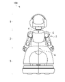
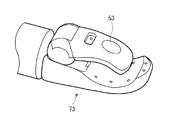
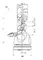
- FIG. 1 is an external view showing an example of external appearance of a nursing care robot according to a first embodiment of the present disclosure when viewed from the front direction and side direction; It is an external view showing an example of the external appearance seen from the back direction of the nursing care robot according to the first embodiment. It is an outline view showing an example of the appearance seen from the front oblique direction of the care robot concerning a 1st embodiment. It is an external view which shows an example of the external appearance seen from the back diagonal direction of the care robot which concerns on 1st Embodiment. It is an external view which shows an example of the external appearance of the hand of the care robot which concerns on 1st Embodiment.
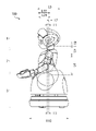
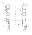
- FIG. 4 is a side view showing parameters of dimensions of each part of the care robot according to the first embodiment; It is a front view showing an example of a dimension of each part of a care robot concerning a 1st embodiment. It is a side view which shows an example of the dimension of each part of the care robot which concerns on 1st Embodiment.
- FIG. 4 is a side view showing parameters of dimensions of each part of the care robot according to the first embodiment; It is a front view showing an example of a dimension of each part of a care robot concerning a 1st embodiment. It is a side view which shows an example of the dimension of each part of the care robot which concerns on 1st Embodiment.
- FIG. 3 is a configuration diagram showing an example of dimensions of each part of the arm of the care robot according to the first embodiment; It is an explanatory view showing an example of a dimension of each part of a care robot concerning a 1st embodiment. It is an explanatory view showing an example of a dimension of each part of a care robot concerning a 1st embodiment. It is an explanatory view showing an example of a dimension of each part of a care robot concerning a 1st embodiment.
- FIG. 4 is an explanatory diagram showing an example of a movable range of a joint axis of each part of the care robot according to the first embodiment; It is an external view which shows one structural example of the eyeball part of the care robot which concerns on 1st Embodiment.
- FIG. 4 is a front view showing parameters of dimensions of the eyeball portion of the care robot according to the first embodiment; It is an exploded view showing an example of an internal configuration of an eyeball portion of the care robot according to the first embodiment.
- 1 is a block diagram schematically showing one configuration example of a robot operation system according to a first embodiment; FIG. FIG.
- FIG. 4 is an explanatory diagram showing an example of an approach position of a nursing care robot operated by the robot operating system according to the first embodiment to a target person;
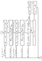
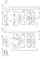
- 7 is a flow chart showing an example of the processing operation of the "greeting calming/vital measurement application" by the robot operation system according to the first embodiment;
- FIG. 24 is a flowchart continued from FIG. 23;
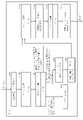
- FIG. 7 is a flow chart showing an example of output processing of evaluation data by the “calm greeting/vital measurement application” by the robot operation system according to the first embodiment;
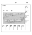
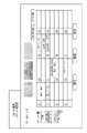
- FIG. 10 is an explanatory diagram showing an example of an output result of evaluation data by the “calm greeting/vital measurement application” by the robot operation system according to the first embodiment;
- FIG. 4 is an explanatory diagram showing an example of creation of execution schedules for a plurality of applications by the robot operation system according to the first embodiment
- FIG. 2 is an explanatory diagram showing an example of a care room that is a target of the robot operation system according to the first embodiment
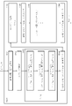
- FIG. 7 is a flow chart showing an example of operation of executing a plurality of applications by the robot operation system according to the first embodiment
- 7 is a flow chart showing an example of an application execution operation when another application interrupts the execution of a plurality of applications by the robot operation system according to the first embodiment
- FIG. 4 is an explanatory diagram showing an example of an application execution schedule setting interface by the robot operation system according to the first embodiment
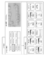
- FIG. 4 is an explanatory diagram showing an example of a setting interface for making individual settings for a person to be cared for by the robot operating system according to the first embodiment; 4 is a flow chart showing an example of the processing operation of the "individual recreation application” by the robot operation system according to the first embodiment; FIG. 34 is a flowchart continued from FIG. 33; FIG. FIG. 4 is an explanatory diagram showing an example of a “monitoring/vital application” by the robot operation system according to the first embodiment; FIG. 4 is an explanatory diagram showing an example of a “tea distribution application” by the robot operation system according to the first embodiment; FIG. 4 is an explanatory diagram showing an example of a “snack distribution application” by the robot operation system according to the first embodiment; FIG.
- FIG. 4 is an explanatory diagram showing an example of a “hand towel distribution application” by the robot operation system according to the first embodiment;
- FIG. 4 is an explanatory diagram showing an example of an "excretion preparation application” by the robot operation system according to the first embodiment;
- FIG. 4 is an explanatory diagram showing an example of a “telephone assistance application” by the robot operation system according to the first embodiment;
- FIG. 4 is an explanatory diagram showing an example of a "story application” by the robot operation system according to the first embodiment;
- FIG. 4 is an explanatory diagram showing an example of an "excretion preparation application” by the robot operation system according to the first embodiment;
- FIG. 4 is an explanatory diagram showing an example of an “excretion cleanup application” by the robot operating system according to the first embodiment;
- Comparative example> (Configuration required for nursing care robots)
- subjects with dementia may become unstable during the staff absence time in the living room and the waiting time of the subject of care, which is caused by a shortage of manpower.
- Examples of destabilization include restlessness, loneliness, and anger.
- destabilization there is a risk of injury due to abrupt standing up or the like, and life rhythms may be disturbed. It also leads to an increase in the level of nursing care required, and the amount of care required will also increase. It is necessary to respond in parallel with private room care, which is highly difficult and places a heavy burden on staff.
- the joint axis configuration in general industrial vertical articulated robot manipulators and humanoid robots is laid out on the same axis without offsetting the axis configuration, mainly focusing on controllability and drive efficiency.
- Controllability and driving efficiency as a robot arm are improved, but the joint axes of the actual human body are not arranged on the same axis, and when trying to make it look like a human to increase acceptability. Secondly, it does not give a natural form and the acceptability decreases.
- robots such as single-arm mobile manipulators are less receptive to elderly people with dementia and are less likely to be recognized as conversation partners.
- table-sized robots are less intimidating due to their small size, but their applications are limited because they cannot move autonomously between nursing care recipients. Even for one person, there are many man-hours for charging management, moving placement, and system management, and the introduction cost is also high.
- robots in the form of mobile cart-type robots and industrial robot manipulators differ from humans in joint axis arrangement and range of motion, and it is difficult to understand what they are doing in their movements. There is a problem that establishment of communication is difficult. As an approach approach to the destination, it is mainly a motion plan that emphasizes the efficiency of time and distance, and the acceptability from the care recipient is not considered.
- Body temperature measurement is particularly needed as an infection prevention measure, and there is a high need for automation.
- a non-contact vital sensor it is possible to attach a non-contact vital sensor to the indoor wall surface or ceiling for automatic measurement, but it is difficult to perform sensing at the optimal measurement position for each person receiving nursing care, and the measurement accuracy is inferior.
- Automatic measurement using a wearable vital sensor is also possible, but the number of man-hours for power supply management, wearing state management, and system management for the number of subjects is large, and the cost is high. Receptivity is low because there are many people who need nursing care, such as wristwatches, accessories, and other wearable items that they are concerned about and accidentally remove or accidentally bump into them.
- a small sensor disguised as a button on clothes may be a possible solution, but the number of man-hours required for individual management is also large.
- FIG. 1 shows an example of the appearance of a nursing care robot 100 according to the first embodiment of the present disclosure as seen from the front direction and side direction.
- a front external view is shown on the left side of FIG. 1, and a side external view is shown on the right side.
- FIG. 2 shows an example of the appearance of the care robot 100 as seen from the rear side.
- FIG. 3 shows an example of the external appearance of the care robot 100 as seen obliquely from the front.
- FIG. 4 shows an example of the appearance of the care robot 100 as seen obliquely from the back.
- FIG. 5 shows an example of the appearance of the hand 73 of the care robot 100.
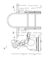
- FIG. 6 shows the size of the care robot 100 and the size of a general table 500 in comparison.
- a care robot 100 includes a head 1 having eyeballs 11 , a chest 2 , and a base 3 that supports the chest 2 .
- the lower portion of the base portion 3 is, for example, an omnidirectional mobile carriage. Thereby, the care robot 100 can move in all directions.
- the care robot 100 also has arms 7 attached to the upper left and upper right sides of the chest 2 .
- the care robot 100 also has a movable neck 4 provided between the head 1 and the chest 2 and having a neck joint axis 4C.
- the care robot 100 also includes a movable shoulder 5 provided between the chest 2 and the arm 7 and having a shoulder joint axis 5C.
- the care robot 100 also has a movable waist 6 which is provided below the chest 2 and has a waist joint axis 6C.
- the arm 7 has an elbow 71, a wrist 72, and a hand 73.
- a head sensor 51 is provided on the front upper portion of the head 1 .
- the head sensor 51 is, for example, a distance image sensor.
- a chest sensor 52 is provided in the front upper part of the chest 2 .
- the chest sensor 52 is, for example, a non-contact vital sensor.
- a hand sensor 53 is provided on the hand 73 .
- the hand sensor 53 is, for example, a contact vital sensor.
- the care robot 100 is operated by a robot operation system, which will be described later.
- the robot operating system according to the first embodiment is a nursing care robot in accordance with a scheduler created based on the judgment of a nursing care staff and robot operation individual settings for each care recipient.
- a plurality of applications are implemented to cause 100 to perform caregiving actions. Applications include calming greetings to care recipients and measuring vital signs.
- Nursing care robot 100 is configured to be able to implement an application aimed at preventing destabilization of the subject of nursing care and regulating life rhythms.
- the nursing care robot 100 is a humanoid mobile manipulator robot capable of performing applications such as condition observation, communication, and peripheral work tasks for the subject of nursing care with a high acceptable quality.
- the care robot 100 is capable of human recognition and face recognition by the head sensor 51, and can carry out an interaction by tracking the subject's eyes.
- the height of the care robot 100 is such that the person being cared for in a sitting posture sitting on a chair can easily look down.
- the height of the care robot 100 is such that the top of a general table 500 can be seen from above, as shown in FIG.
- the head sensor 51 is, for example, a distance image sensor.
- the head sensor 51 is configured such that the sensing direction is substantially the same as the line-of-sight direction of the care robot 100 so that humanitude motion, face tracking motion, and the like can be practiced.
- the height of the general table 500 is, for example, about 700 mm
- the height of the general table 500 in nursing care facilities is, for example, about 660 mm.
- the head sensor 51 is arranged at a position where the top plate 501 of the table 500 can be overlooked.
- the head 1 is positioned to look up at the face of the person to be cared for while sitting on a chair (sitting posture).
- the head sensor 51 is mounted upward by, for example, about 5 degrees at a high position of the head 1 (for example, at a height of about 760 mm).
- the head sensor 51 is arranged so as not to protrude too far from the outer diameter line of the head 1 .
- recognition of an object on a standard table 500 and face recognition of a person to be cared for in a sitting posture over the table 500 are possible.
- the chest sensor 52 is, for example, a non-contact vital sensor.
- Non-contact vital sensors include, for example, body temperature sensors, heartbeat sensors, and respiration sensors.
- the chest sensor 52 is mounted upward, for example, by about 10 degrees at a position in the front upper portion of the chest 2 (for example, at a height of about 537 mm). This enables measurement by the chest sensor 52 without being affected by the motion of the head 1 . Also, it is possible to reduce the occurrence of blind spots caused by the arm 7 during manipulation.
- the hand sensor 53 is, for example, a contact vital sensor.
- Contact-type vital sensors include, for example, a heartbeat sensor, a blood pressure sensor, an oxygen saturation sensor, and the like.
- the hand sensor 53 is arranged outside the thumb at the tip of the hand 73 as shown in FIG. 5, for example. As a result, the subject's hand is not pinched by the hand 73 during vital sensing. Vital sensing can be performed by having the target person place or hold the hand instead of going to the hand sensor 53 by himself/herself.
- Such a hand sensor 53 is a familiar interface for the elderly with dementia, and is highly acceptable to the subject.
- a sensor for gripping force control can be separately configured inside the hand.
- FIG. 7 is a front view showing dimensional parameters of each part of the care robot 100 .
- FIG. 8 is a side view showing dimensional parameters of each part of the care robot 100 .
- FIG. 9 is a front view showing an example of dimensions of each part of the care robot 100.
- FIG. 10 is a side view showing an example of dimensions of each part of care robot 100.
- FIG. 11 is a configuration diagram showing an example of dimensions of each part of the arm 7 of the care robot 100.
- FIG. 12 to 14 are explanatory diagrams showing examples of dimensions of each part of the care robot 100.
- FIG. FIG. 15 is an explanatory diagram showing an example of the movable range of the joint shaft of each part of the care robot 100. As shown in FIG.
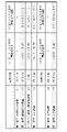
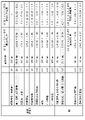
- FIGS. 9 to 11 show examples of the best values for the dimensions of each part.
- 12 to 14 show an example of the best value of the dimensions of each part, an example of the best value of the dimensional ratio of each part, and an example of the allowable ratio range of the dimensional ratio of each part. Note that the specific numerical values shown in FIGS. 9 to 15 are examples, and other numerical values can be used.
- the care robot 100 when viewed from the side in the standard posture, has a neck joint axis 4C offset rearwardly with respect to a shoulder joint axis 5C, and a waist joint axis 6C. It is offset in the forward direction with respect to the shoulder joint axis 5C.
- the front-rear positions of the three joint shafts of the neck joint shaft 4C, the shoulder joint shaft 5C, and the waist joint shaft 6C are offset in the same backward direction instead of being vertically aligned. are arranged as
- Nursing care robot 100 satisfies the following conditional expressions (1) and (2) so that the three joint axes are offset as described above.
- L1 is the longitudinal distance between the waist joint axis 6C and the shoulder joint axis 5C
- L2 is the longitudinal distance between the shoulder joint axis 5C and the neck joint axis 4C
- L2 is the distance between the waist joint axis 6C and the shoulder joint axis 5C.
- L4 be the vertical distance
- L5 be the vertical distance between the shoulder joint axis 5C and the neck joint axis 4C. 0 ⁇ L2/L1 ⁇ 1.5 (1) 0.2 ⁇ L5/L4 ⁇ 0.6 (2)
- the care robot 100 is configured to satisfy the following conditional expression (3) regarding the head and body.
- the head and body are configured to be relatively large.
- the total head height (height) in the standard posture is L6, and the height is L7. 3.3 ⁇ L7/L6 ⁇ 5.0 (3)
- the eyeball part 11 is arranged at a lower position than the center position of the head 1 in the vertical direction.
- Nursing care robot 100 is configured to satisfy the following conditional expression (4) regarding the position of eyeball portion 11 .
- the total head height in the standard posture is L6, and the vertical distance from the center position of the eyeball portion 11 to the bottom of the head 1 under the chin is L17. 0.2 ⁇ L17/L6 ⁇ 0.5 (4)
- the care robot 100 is configured such that the length of the neck 4 is so short that the upper end of the chest 2 and the lower jaw of the head 1 are substantially in contact with each other when viewed from the front. For this reason, it is configured to satisfy, for example, the following conditional expression (5).
- the vertical distance between the shoulder joint axis 5C and the neck joint axis 4C is L5
- the total head height in the standard posture is L6. 0.3 ⁇ L5/L6 ⁇ 0.6 (5)
- the nursing care robot 100 is configured such that the lower part (cheek shape) of the head 1 is larger than the eyeball part 11 so that the upper end of the chest 2 and the lower jaw of the head 1 are substantially in contact with each other when viewed from the front. It is For this reason, it is configured to satisfy, for example, the following conditional expressions (6) and (7).
- L17 is the vertical distance from the center of the eyeball 11 to the bottom of the jaw of the head 1
- L18 is the vertical distance from the center of the eyeball 11 to the shoulder joint axis 5C
- L18 is the center of the eyeball 11.
- Let L19 be the vertical distance from the position to the neck joint axis 4C. 1.3 ⁇ L18/L17 ⁇ 2.5 (6) 0.4 ⁇ L19/L17 ⁇ 1.0 (7)
- the care robot 100 is configured such that the range of motion of the pitch axis of the neck 4 is larger in the upward direction than in the downward direction (see FIG. 15).
- the front face of the head 1 and the front of the chest 2 are at approximately the same position, and the front face of the head 1 is It is configured to be on the rear side of the front part of the chest 2.
- L21 is the distance from the neck joint axis 4C to the front face of the head 1 when viewed from the lateral direction in the standard posture, and the front surface of the chest 2 from the neck joint axis 4C when viewed from the lateral direction in the standard posture.
- the distance to the part be L22. 1 ⁇ L22/L21 ⁇ 1.3 (8)
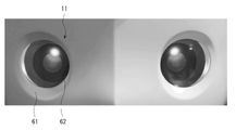
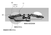
- FIG. 16 and 17 are external views showing one configuration example of the eyeball part 11 of the care robot 100.
- FIG. FIG. 18 is a cross-sectional view showing one configuration example of the eyeball portion 11 of the care robot 100.
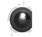
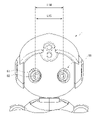
- FIG. 19 is a front view showing dimensional parameters of the eyeball portion 11 of the care robot 100 .
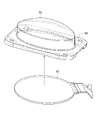
- FIG. 20 is an exploded view showing an internal configuration example of the eyeball portion 11 of the care robot 100. As shown in FIG.
- the eyeball part 11 has a transparent solid cylindrical part 64 having a first end face and a second end face, as shown in FIG.
- the eyeball portion 11 also has a flat display 65 that is provided on the first end surface side (lower side in FIG. 20) of the cylindrical portion 64 and displays the operation of the black eye portion 62 .
- the eyeball portion 11 is provided on the second end face side (the upper side in FIG. 20) of the cylindrical portion 64, and is a hemispherical transparent spherical portion that emits the display light from the display 65 that has entered through the cylindrical portion 64.
- the spherical portion 63 constitutes a hemispherical transparent spherical lens.
- the outer peripheral shape of the spherical portion 63 is configured to form the white portion 61 as shown in FIG. 16 .
- the center position of the eyeball of the eyeball portion 11 is configured to be offset inwardly with respect to the center position of the outer periphery of the spherical portion 63, as shown in FIG.
- the care robot 100 is configured such that the eyeball portion 11 has a hemispherical transparent spherical portion 63 and a transparent solid cylindrical portion 64 . Then, the spherical portion 63 and the cylindrical portion 64 are superimposed on a planar display 65 that displays the operation of the black eye portion 62 .
- the outer peripheral surface of the cylindrical portion 64 is configured to be non-transmissive so as to prevent light from entering. As a result, the display image seen from the spherical surface portion 63 without distortion becomes clear. Since the spherical portion 63 is arranged at a distance from the display 65, a three-dimensional effect of depth is produced.
- the spherical portion 63 is configured to have a certain amount of luster and suppress reflection of light.
- the circular colored part expresses the movement (line of sight) of the black eye part 62 in the vertical and horizontal directions.
- the center of the sphere of the spherical portion 63 is designed as the virtual center of rotation of the eyeball, and the movement of the black eye portion 62 to be displayed is also controlled with the center of the sphere of the spherical portion 63 as a reference.
- the cylindrical portion 64 By providing the cylindrical portion 64, a more natural spherical shape is realized with the initial position of the black eye slightly shifted inward.
- human recognition and face recognition are performed using the head sensor 51, and by controlling the position of the black eye part 62 of the eyeball part 11 and the axes (Roll, Pitch, Yaw) of the neck 4, Gaze at the target.
- the position of the black eye portion 62 the target person's position is followed up, down, left, and right, and the gaze is performed, and the distance to the target person is expressed using the angle of convergence (crossed eyes, distant eyes).
- the configuration makes it easy for the subject to understand where the line of sight of the care robot 100 is directed (especially in the perspective direction). Elderly people with dementia in nursing homes are required to be highly receptive and recognizable.
- the eyeball part 11 is configured to meet this need.
- the eyeball part 11 has a three-dimensional structure, and the movement of the black eye part 62 can be displayed at low cost. As a result, a face with eyes as if they contained eyeballs was realized.
- the spherical portion 63 is composed of a hemispherical spherical lens, the lens effect is not distorted and the eyeball does not feel uncomfortable. Since the highlights of the eyes can be expressed as the reflected light of the real light, the responsiveness is real-time and there is no sense of incongruity.
- the eyeball part 11 unlike a flat display, it is displayed on the built-in sphere with good visibility from any angle, or it looks like it is moving, there is no distortion, and it looks like an eyeball. .
- the center of the black eye portion 62 and the center of the sphere of the spherical surface portion 63 are aligned, and the thickness and shape of the spherical surface are comfortable.
- the reflected light of the ambient light is reflected on the surface of the spherical portion 63, and the highlight of the pupil can be expressed naturally in real time. It has the effect of providing the subject of nursing care with a sense of eye contact.
- the nursing care robot 100 increases the acceptability of the actual configuration of the robot hardware from the person receiving nursing care in an environment where people coexist (it is easy to understand what they are doing without being frightened). can be specified. In particular, it is possible to increase the acceptability of nursing care recipients with cognitive characteristics, such as elderly people with dementia and infants.
- the nursing care robot 100 has the following actual configuration that enhances acceptability.
- the size it has a sense of reality equivalent to that of a 2-year-old child, is moderately small, is at a height that a sitting elderly person can look down on, and is configured so that the person being cared for is not intimidated and fearless.
- the height of the head 1 is configured so that the top of a general table 500 can be overlooked.
- the height of the shoulders 5 and the length of the arms 7 are such that the edge of a general table 500 can be approached. In terms of form, it has a large head and body, and is said to resemble a cute grandchild.
- the eyeball portion 11 is positioned at a height where eyes can easily meet, and the care recipient can understand the meaning of the line of sight and the image displayed on the eyeball portion 11 .
- movement it does not have a different degree of freedom axis or range of motion than humans, so it is not scary to move, and it is configured to know what it is doing. It is configured to enable the practice of Humanitude Motion. It is configured to enable implementation of basic applications in active monitoring robots.
- One robot can handle the number of care recipients for one unit (about 10 people) of a nursing care facility.
- the QOL Quality of Life
- the QOL Quality of Life
- the number of people who wish to enter facilities that have been introduced increases.
- the number of people who wish to work as caregivers and nursing staff at the introduced facilities will increase.
- the sensor position it becomes easier to create a wide space in the upper front position of the head 1 and the upper front position of the chest 2, so the degree of freedom in sensor layout increases. For example, it is possible to arrange the sensor at a position with good vital sensing performance for a person to be cared for in a sitting or standing posture. 2. Parts are likely to be concentrated in the front of the head and the weight tends to be large, but the three joint axes of the neck joint axis 4C, the shoulder joint axis 5C, and the waist joint axis 6C are arranged so that their front-rear positions are offset in the same rearward direction. Therefore, the center of gravity balance above the waist 6 is less likely to be eccentrically loaded.
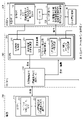
- FIG. 21 schematically shows a configuration example of the robot operation system according to the first embodiment.
- the robot operation system includes a controller 210, a large information terminal 310, a center PC (personal computer) 320, a care robot 100, and a small information terminal .
- the care robot 100 is operated in a care room 400 having a living room 401 and a living room 402, for example, as shown in FIG. 28 which will be described later.
- a plurality of nursing care robots 100 may exist.
- a plurality of nursing care robots 100 may be operated simultaneously by the robot operating system according to the first embodiment.
- Nursing care robot 100 has various sensors 110 , speaker 111 , and robot internal PC 120 .
- the various sensors 110 include a vital sensor, a microphone, a distance image sensor, an omnidirectional distance sensor, a tactile sensor, and a force sensor. Some of the various sensors 110 are provided in the head sensor 51, the chest sensor 52, and the hand sensor 53 described above.
- the robot internal PC 120 has a motor drive control section, a movement path control section, an eyeball display control section, and a voice input/output control section.
- the robot internal PC 120 may be configured by a computer including, for example, a CPU (Central Processing Unit), ROM (Read Only Memory), and RAM (Random Access Memory).
- various processes by the robot internal PC 120 can be realized by the CPU executing processes based on programs stored in the ROM or RAM.
- various processes by the robot internal PC 120 may be implemented by the CPU executing processes based on programs externally supplied via a wired or wireless network, for example.
- the compact information terminal 130 has an information display monitor and an operation panel.
- the small information terminal 130 can be held by the hand 73 of the care robot 100 .
- the controller 210 is a robot controller device that can be carried or worn by the employee 200. Multiple controllers 210 may be present and portable by multiple personnel 200 .
- the controller 210 has a headset 211 (earphone, speaker, microphone) and a small information terminal (information display monitor, operation panel) 212 . Since the care recipient 101 may reach out for the accessories, the earphone of the headset 211 should have an inconspicuous appearance such as a small inner earphone type.
- Voice input from the controller 210 enables command operations (selection of the subject 101, application selection, start, stop, etc.) to the care robot 100 in real time.
- the staff member 200 is also notified through the controller 210 of the presentation of the monitoring result from the nursing care robot 100 and the presentation of an abnormality. Moreover, it is also possible to output the voice of the staff member 200 to the target person 101 from the speaker 111 of the care robot 100 via the controller 210 .
- Headset 211 has an earphone, a speaker, and a microphone.
- a small information terminal 212 has an information display monitor and an operation panel 212 .
- the small information terminal 212 corresponds to a specific example of the "information terminal" in the technology of the present disclosure.
- the large information terminal 310 and the center PC 320 are arranged in the staff room 300, for example.
- the large information terminal 310 has, for example, an information display monitor and an operation panel.
- the center PC 320 has a sensor information processing section 321 , a measurement result analysis storage section 322 and an application generation section 323 .
- the center PC 320 may be configured by a computer having a CPU, ROM, and RAM, for example.
- various processes by the center PC 320 can be realized by the CPU executing processes based on programs stored in the ROM or RAM.
- various processes by the center PC 320 may be implemented by the CPU executing processes based on programs externally supplied via a wired or wireless network, for example.
- the application generation unit 323 has an individual user setting data storage unit 324 and an application execution schedule data storage unit 325 .
- the sensor information processing unit 321 corresponds to a specific example of the "information processing unit” in the technology of the present disclosure.
- the application generation unit 323 corresponds to a specific example of the “behavior control unit” in the technology of the present disclosure.
- the individual user setting data storage unit 324 corresponds to a specific example of the “individual setting storage unit” in the technology of the present disclosure.
- the application execution schedule data storage unit 325 corresponds to a specific example of the “schedule storage unit” in the technology of the present disclosure.
- the measurement result analysis storage unit 322 corresponds to a specific example of the “evaluation data storage unit” in the technology of the present disclosure.
- Some or all of the processing performed by the center PC 320 may be performed by the robot internal PC 120 . Also, a part or all of the processing performed by the center PC 320 may be performed by a server on the cloud.
- the real need from the nursing care facility is to stabilize the mental state of the subject 101 of nursing care by watching over (state observation and communication) while the staff member 200 is absent.
- the nursing care robot 100 which can actively go to acquire information, watches over the nursing care target person 101 in advance and continues approaches such as greetings, voices, prompting, etc. Calm the state and try to preserve the stable state.
- the group of applications installed in the robot operating system aims to reduce the work load on the staff member 200 and further stabilize the mental state of the care recipient 101 .
- the sensor information processing unit 321 evaluates the condition of the subject of care based on measurement information measured by various sensors 110 mounted on the care robot 100 . Based on the result of the evaluation by the sensor information processing unit 321, the application generating unit 323 temporarily stops the nursing care robot 100 at a plurality of approach positions (waypoints) with different distances from the subject, and moves the nursing care robot 100 to the subject. , and causes the care robot 100 to perform care actions including observation of the subject's condition and communication. Communication to the target includes speech to the target.
- the plurality of approach positions may be, for example, a long-distance position P3, a middle-distance position P2, and a short-distance position P1 shown in FIG. 22, which will be described later.
- the sensor information processing section 321 may evaluate the subject's condition based on measurement information measured at each of a plurality of approach positions.
- the evaluation of the subject's condition by the sensor information processing unit 321 includes evaluation of whether or not the subject has a negative reaction.
- the application generation unit 323 may cause the nursing care robot 100 to approach the subject step by step.
- FIG. 22 schematically shows an example of an approach position of the nursing care robot 100 operated by the robot operation system according to the first embodiment to the target person.
- the application generation unit 323, temporarily stops the nursing care robot 100 in stages from the initial position P0 ⁇ long distance position P3 ⁇ middle distance position P2 ⁇ short distance position P1.
- the application generation unit 323 causes the nursing care robot 100 to align its face and posture with the facial direction of the target person 101 , for example, and execute speech and motion directed toward the target person 101 .
- the long-distance position P3 is near the distance radius of 2 m in the forward direction with respect to the subject 101
- the intermediate-distance position P2 is near the distance radius distance of 1.2 m in the forward direction with respect to the subject 101
- the short-distance position P1 may be around 0.6 m in the forward radial distance with respect to the subject 101 .
- the application generation unit 323 observes the reaction of the subject 101 each time it stops at each approach position (route point), and moves the care robot 100 to the subject 101 step by step while confirming that there is no negative reaction. to approach.
- a recognition result such as an extreme and large posture change is defined as a state of reluctance or surprise.
- the sensor information processing section 321 may further determine the presence or absence of an obstacle based on the measurement information.
- the application generation unit 323 changes the approach angle of the care robot 100 from the front direction to the target person 101 based on the presence or absence of an obstacle facing the front of the target person 101 determined by the sensor information processing unit 321.
- Obstacles may be, for example, desks, chairs, cabinets, and the like.
- the application generation unit 323 may cause the nursing care robot 100 to approach the target person 101 at a larger angle of approach.
- the application generating unit 323, as shown in FIG. The approach angle of the nursing care robot 100 may be changed so that it approaches 45 degrees with respect to the subject 101 at the intermediate position P2 and approaches 70 degrees with respect to the subject 101 at the short distance position P1.
- the application generating unit 323 approaches the nursing care robot 100 while maintaining the same approach angle in the front direction regardless of the distance to the subject 101. You can let it run. For example, when there is no obstacle directly facing the target person 101, the application generating unit 323 generates 0 degree The care robot 100 may be approached at an angle near the direction.
- the application generation unit 323 may cause the nursing care robot 100 to approach the target person 101 so that the angle of approach increases in the direction of the dominant hand of the target person 101 as it approaches the target person 101 .
- the sensor information processing unit 321 may determine whether or not the care robot 100 can move in the direction of the dominant hand of the subject 101 based on the measurement information. Whether or not it is possible to move may be determined based on, for example, the presence or absence of an obstacle, or the width of the passable floor area.
- the application generation unit 323 moves the care robot 100 from a direction different from the subject's 101 dominant hand direction. You may make it approach.
- the measurement result analysis storage unit 322 stores evaluation data indicating evaluation results by the sensor information processing unit 321 .
- the sensor information processing unit 321 generates, as evaluation data, evaluation data indicating the receptivity of the subject 101 to the nursing robot 100 based on the measurement information measured by the various sensors 110 when the nursing robot 100 is caused to perform the nursing care action. may be generated (see later-described FIGS. 25, 26, and 32).
- the application generation unit 323 may cause the nursing care robot 100 to perform nursing care actions based on the evaluation data indicating acceptability stored in the measurement result analysis storage unit 322 (FIGS. 21 to 26 described later, FIG. 32).
- the evaluation data includes the gaze time of the subject 101 toward the care robot 100 (the time during which the face and eyes are aligned, etc.), the utterance time of the subject 101, whether or not a smile of the subject 101 is detected, and negative reactions. The presence or absence of, etc. may be included.
- This evaluation data may be defined as an acceptability value.
- the application generating unit 323 obtains the optimum approach distance and approach that match the receptivity of each subject 101, and causes the care robot 100 to perform caregiving actions.
- the application generation unit 323 applies humanitude to the nursing care robot 100 based on the cognitive characteristics of the subject 101 and the receptivity of the subject 101 to the nursing care robot 100. You may be made to perform the care action which said.
- the application implementation schedule data storage unit 325 stores implementation schedule data for a plurality of applications for causing the nursing care robot 100 to perform nursing care actions.
- the application generating unit 323 may cause the nursing care robot 100 to perform nursing care actions by each application according to the implementation schedule stored in the application implementation schedule data storage unit 325 (see FIGS. 27 to 31 described later).
- the application execution schedule data storage unit 325 is set based on an instruction from the small information terminal 212, and is related to the selection of the application to be executed according to the execution schedule, the selection of the target person 101 to execute the application, and the time to execute the application.
- the information is stored as setting data of the implementation schedule (see FIGS. 27 and 31 described later).
- the application generation unit 323 After having the nursing care robot 100 execute the nursing care action by each application according to the implementation schedule stored in the application implementation schedule data storage unit 325, the application generation unit 323 generates the implementation schedule stored in the application implementation schedule data storage unit 325. You may make it correct setting data based on the result of having performed care action.
- the application generation unit 323 generates, for example, the basic application “calm down greeting/vital measurement” and the application applications such as “recreation,” “tea serving,” “excretion assistance,” and “visiting assistance,” for example. may be executed according to the shift table set by the scheduler.
- the small information terminal 212 accepts setting of the implementation schedule from the care facility staff 200 .
- the application generation unit 323 may present the setting data of the revised implementation schedule to the small information terminal 212 so that the staff member 200 of the nursing care facility can edit the setting data.
- the individual user setting data storage unit 324 stores individual operational parameters of the care robot 100 for the target person 101, which are set based on information about the acceptability of the target person 101 to the care robot 100 (see FIG. 32 described later). .
- the application generating unit 323 may cause the nursing care robot 100 to perform nursing care actions based on the operation parameters of the nursing care robot 100 stored in the individual user setting data storage unit 324 .
- the operational parameters may include, for example, settings related to whether or not to call out, volume of voice, speaking speed, body movement speed, moving speed, accessible distance, whether or not physical contact is possible, tastes and preferences, and other special items. Operation parameter settings are received from nursing care facility staff 200 via small information terminal 212 .
- the application generation unit 323 After causing the nursing care robot 100 to perform a nursing action based on the operation parameters of the nursing care robot 100 stored in the individual user setting data storage unit 324, the application generation unit 323 causes the operation parameters stored in the individual user setting data storage unit 324.
- the operating parameters of the nursing care robot 100 are corrected based on the result of executing the nursing care action, and the corrected operating parameters of the nursing care robot 100 are presented on the small information terminal 212 so that they can be edited by the care facility staff 200. You may make it
- the application generation unit 323 feedback-learns the evaluation result for each application execution, automatically generates and proposes a correction plan for individual settings and a schedule correction plan, and the staff member 200 confirms and edits these, so that the care robot 100 can provide care. You may make it perform an action.
- FIG. 23 is a flow chart showing an example of the processing operation of the "calm down greeting/vital measurement application" by the robot operation system.
- FIG. 24 is a flowchart following FIG.
- FIG. 25 is a flowchart showing an example of output processing of evaluation data by the “calm down greeting/vital measurement application” by the robot operation system.
- FIG. 26 shows an example of an output result of evaluation data by the "calm greeting/vital measurement application” by the robot operation system.
- FIG. 27 shows an example of creating an execution schedule for a plurality of applications by the robot operation system.
- FIG. 28 shows an example of a care room that is a target of the robot operation system.
- FIG. 29 is a flow chart showing an example of operation of executing a plurality of applications by the robot operation system.
- FIG. 30 is a flow chart showing an example of an application execution operation when another application interrupts the execution of a plurality of applications by the robot operation system.
- FIG. 31 shows an example of an application execution schedule setting interface by the robot operation system.
- FIG. 32 shows an example of a setting interface for making individual settings for the person 101 to be cared for by the robot operating system.
- FIG. 33 is a flow chart showing an example of the processing operation of the "individual recreation application" by the robot operation system.
- FIG. 34 is a flowchart following FIG.
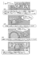
- FIG. 35 shows an example of a "monitoring/vital application" by the robot operation system.
- FIG. 36 shows an example of a "tea distribution application” by the robot operation system.
- FIG. 37 shows an example of a "snack distribution application” by the robot operation system.
- FIG. 38 shows an example of a "hand towel distribution application” by the robot operation system.
- FIG. 39 shows an embodiment of the "excretion preparation application” by the robot operation system.
- FIG. 40 shows an example of a "telephone assistance application” by the robot operation system.
- FIG. 41 shows an embodiment of the "story application” by the robot operation system.
- FIG. 42 shows an embodiment of the "excretion preparation application” by the robot operation system.
- FIG. 43 shows an embodiment of the "excretion cleaning application” by the robot operating system.
- the application generation unit 323 provides a scheduler.
- the application generation unit 323 automatically generates and proposes an execution pattern/scheduling set of applications to be executed by the care robot 100 in a day.
- the application generation unit 323 generates changes in the state of the care recipient 101 in the care facility (the degree of dementia, physical condition, change in feelings, as well as the degree of receptivity to the care robot 100 is included in parameters), the work of the staff 200
- An optimum application set is proposed for minimizing the absence time of the employee 200 in the living room 401 (FIG. 28) in response to daily changes such as shift changes.
- the application generator 323 provides a monitoring (state observation and communication) application as a base load, and provides a peripheral business application and a recreation application as an extension of the monitoring application on top of the base application.
- Examples of applications provided by the application generation unit 323 are shown below.
- Active monitoring Morning monitoring, daytime monitoring, night monitoring, late-night monitoring
- Indirect assistance Vital measurement - long-distance non-contact (body temperature, heart rate) - Close contact (body temperature, blood pressure, oxygen saturation) Ordering, handing out wet towels, handing out snacks, handing out tea
- Peripheral work Excretion preparation, excrement cleanup, desk cleaning, tea serving, snack serving, cup washing, tea making
- Story memory photos, stories about hobbies and tastes, etc.), singing, dancing, gymnastics, hand massage , Help with what you want to do (Tell me what you like), Phone help (Telephone with family)
- the above application list is the result of consideration of needs (level of problems), functions, value to be obtained, and technical feasibility from among 50 items of applications that may be used in nursing care site work that were created in advance. , the selection is made in order of importance under the supervision of the staff member 200 .
- Active monitoring which is a basic application, (1) Differences between morning, noon, night, and midnight (2) Differences between states on bed in living room 402 (Fig. 28) and on wheelchair in living room 401 (Fig. 28) (3) Care recipient 101 Degree of dementia (4)
- Individual approaches such as how to keep a distance from the target person 101, how to approach the target person 101, greetings, and dialogue content, are optimized according to the target person 101, and can be executed through a schedule and sensing results.
- An individual approach is automatically generated for each target person 101 by the application generating unit 323 and presented to the large information terminal 310 or the small information terminal 212 .
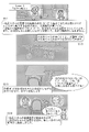
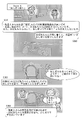
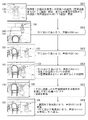
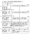
- FIGS. 35-39 Typical storyboards for the above application are shown in FIGS. 35-39.
- Figures 33 and 34 show the execution flow of an individual recreational application that can be realized by using the receptivity-enhancing approach, which is the essence of the robot operating system. This is an application that conducts a dialogue using related photographic images, in-depth knowledge of what each target person 101 wants to do, and conveys the information to the employee 200 and family members, thereby providing support for fulfilling what the target person 101 wants to do.
- the application generation unit 323 calculates the estimated required execution time for each application and care recipient 101 (calculated from past required time data), and also calculates the required charging standby time from the remaining power supply of the care robot 100. , automatically generates a schedule shift table of applications that can be executed within a predetermined time.
- the estimated required implementation time for each care recipient 101 is calculated from the application content, the location of the care recipient 101, and individual settings (moving speed, speech speed, user characteristics (amount of speech, preferences, etc.), etc.).
- An example of creating a daily schedule is shown in Fig. 27.
- Information such as the name of the subject 101, the arrangement of seats 404, and the arrangement of rooms 402 is also registered first and used as target position information (Fig. 28).
- the position of the seat 404 and the living room 402 in one unit of the nursing care facility.
- the position of the seat 404 and the living room 402 are used to determine the approach to the care recipient 101.
- the autonomous movement control load and the human recognition and discovery load of the care robot 100 are reduced, and the realization stability of the application is improved.
- the application is executed according to the set scheduler after confirmation by the employee 200 (Fig. 29).
- the care robot 100 charges at the charging standby point 403 (FIG. 28) in the living room 401 before and after executing the application. Further, the center PC 320 saves the input data when executing the application.
- the care robot 100 constantly watches over the living room 401 at a fixed fixed point. While watching over living room 401 by fixing a fixed point, nursing care robot 100 continues to detect anomalies in the observable range by tracking, voice input, and body temperature measurement.
- the robot operating system In order to schedule the charging time of the nursing care robot 100 with a margin, the robot operating system also reduces the standby time and allocates it to the application execution time. A request by the employee 200 and an interrupt application are also judged to have a high priority and are processed by interrupting the schedule. A schedule after interruption is automatically selected from execution patterns A, B, and C based on the remaining power supply of the care robot 100, the remaining application execution time, and the next standby chargeable time, and executed.
- the application with the lowest execution priority is canceled, and priority is given to the execution of the next scheduler.
- the waiting time is also reduced and allocated to the application execution time.
- an execution schedule for the application of the care robot 100 is created on a weekly basis.
- a monthly implementation schedule is created with Week 1 from Day 1 to Day 7 and Month 1 from Week 1 to Week 4 (or Week 5 depending on the month).
- the robot operation system asks the employee 200 to correct the work shift and reflects the work data. Automatically generate schedules and detailed flows.
- the robot operation system has a programming tool for staff 200 to manually adjust the application schedule set for care robot 100 presented by the scheduler (Fig. 31). It also has a tool for making individual settings for the care recipient 101 (FIG. 32). As the individual setting of the care recipient 101, the operation parameters of the care robot 100 (possibility of calling, voice volume, speech speed, body movement speed, movement There are settings related to speed, accessible distance, physical contact availability, hobbies and preferences, and other special considerations).
- the setting operation is performed using the small information terminal 212 . Using the small information terminal 212, the employee 200 can select an application and its timing according to the target person 101 from a list and rearrange them by drag and drop. Personnel 200 can also determine and execute application usage in real time. In the robot operation system, the adjustment results based on the judgment of the staff 200 using the tools shown in FIGS. 31 and 32 are compiled into a database and used for learning, thereby improving the quality of automatically generated results such as individual settings.
- the robot operating system according to the first embodiment is not a fully autonomous robot system. It is difficult even for AI (artificial intelligence) to generate behavioral changes of nursing care robot 100 that respond to complex situational changes in nursing care sites. It is a system that Quality care can only be achieved by humans.
- the robot operation system is a means to extend the person's body, make an alter ego, and fulfill their wishes.
- FIG. 23 and FIG. 24 show the processing flow of an embodiment of the basic application "greeting to calm down/vital measurement".
- the positional distance and angle values shown in FIGS. 23 and 24 are representative examples, and it is important to go through the stages of long, medium, and short distances.
- Optimum values are set for each subject 101 for the above numerical values.
- the care robot 100 performs greetings by speech and motion, measures vitals, checks for negative reactions while measuring reactions, and moves between waypoints.
- FIG. 25 shows the flow of this sensing.
- the measured evaluation data is output as a table so that the employee 200 can confirm it, and can be displayed on a small information terminal 12 such as a tablet operated by the employee 200 (FIG. 26).
- the application execution end instruction can be given by voice instruction or the like.
- approach parameters for each target person 101, the approach distance, the angle relative to the target person 101, and the coordinate position of the hand are stored as data for the correction amount of hand approach position. is raised.
- the care robot 100 performs standby charging and fixed-point monitoring at the initial position P0 (standard standby position) (step S101).
- the robot operation system activates the scheduler set at time t1 (step S102).
- the robot operation system starts executing the application (user No. 1, place No. 1, individual setting No. 1) set at time t1-1 (step S103).
- the robot operation system selects the seat number. 1 (step S104).
- the robot operation system assigns the user number to the care robot 100 . 1 face is searched (step S105). If the person (person to be cared for 101) can be found in step S105, the robot operation system next proceeds to the process of step S108.
- step S105 If the person is not found in step S105, next, the robot operation system ends execution of the application set at time t1-1, and moves the care robot 100 to the initial position P0 (step S106). Next, the robot operation system starts executing the application (user No. 2, location No. 2, individual setting No. 2) set at time t1-2 (step S107).
- step S105 if a person can be found in step S105, then the robot operation system causes the care robot 100 to start speaking/moving and perform non-contact vital measurement (body temperature) (step S108). If there is a negative response in step S108, or if there is an approachable distance setting, then the robot operation system proceeds to processing in step S106. If there is no negative reaction in step S108, then the robot operation system determines the seat number. 1, the care robot 100 is moved to the short distance position P2 (1.2 m obliquely 45 degrees forward position from the sitting position) (step S109).
- the short distance position P2 1.2 m obliquely 45 degrees forward position from the sitting position
- step S109 If there is a negative response in step S109, then the robot operation system proceeds to processing in step S106. If there is no negative reaction in step S109, next, the robot operation system causes the care robot 100 to start speaking/moving, and causes the care robot 100 to perform non-contact vital measurement (body temperature) (step S110). If there is a negative response in step S110, or if there is an approachable distance setting, then the robot operation system proceeds to processing in step S106. If there is no negative reaction in step S110, then the robot operation system determines the seat number. 1 (step S111).
- step S111 If there is a negative response in step S111, then the robot operation system proceeds to processing in step S106. If there is no negative reaction in step S111, next, the robot operation system causes the care robot 100 to start speaking/moving, makes the care robot 100 perform non-contact vital measurement (body temperature), and contact vital measurement (heart rate). , blood pressure, oxygen saturation) are executed (step S112). If there is a measurement error in step S112, the robot operation system then corrects the hand approach position (step S114) and performs the process of step S112 again. When the measurement is completed in step S112, next, the robot operation system causes the nursing care robot 100 to make an utterance/motion to end the application (step S113). Next, the robot operation system moves the nursing care robot 100 to the middle distance position P2, starts the ending utterance/motion (step S115), and then proceeds to the process of step S106.
- body temperature body temperature
- contact vital measurement heart rate
- blood pressure, oxygen saturation blood pressure, oxygen saturation
- the robot operation system performs scheduler, individual setting, speech motion, and database processing (step S201).
- the robot operation system starts executing the application (user No. 1, place No. 1, individual setting No. 1) set at time t1-1 (step S202).
- the robot operation system moves the nursing care robot 100 to the long-distance position P3 (position 2m in front of the sitting position) and performs speech/motion/sensing (step S203). If there is no negative reaction in step S203, next, the robot operation system moves the nursing care robot 100 to a short distance position P2 (1.2 m obliquely 45 degrees forward position from the sitting position), and performs utterance/motion/sensing. be implemented (step S204). If there is no negative response in step S204, next, the robot operation system moves the nursing care robot 100 to a short distance position P1 (0.6 m diagonally 70 degrees forward position from the sitting position), and performs utterance/motion/sensing. be implemented (step S205). Next, the robot operation system terminates execution of the application set at time t1-1 (step S206).
- the robot operation system collects, as evaluation data, gaze time (face and eye direction match), speech time, presence/absence of smile detection, and presence/absence of negative reaction. is output (step S207).
- the care robot 100 performs standby charging and fixed-point monitoring at the initial position P0 (standard standby position) (step S301).
- the robot operation system activates the scheduler set at time t1 (step S302).
- the robot operation system executes application A (step S303).
- Application A includes the application set at time t1-1 (user No. 1, location No. 1, individual setting No. 1), the application set at time t1-2 (user No. 2, location No. 1). 2, individual setting No. 2), and applications set at time t1-n (user No. n, place No. n, individual setting No. n) are executed in sequence.
- the robot operation system performs standby charging of the care robot 100 at time t1-0. Further, in the robot operating system, data obtained by executing application A is saved, and fixed-point watching is performed by the care robot 100 at the initial position P0 (standard standby position) (step S304). Next, the robot operation system activates the scheduler set at time t2 and executes application B (step S305). Next, the robot operation system performs standby charging of the care robot 100 . Also, the data obtained by executing the application B is saved, and fixed-point watching is performed by the care robot 100 at the initial position P0 (standard standby position) (step S306). Next, the robot operating system activates the scheduler set at time tn and executes application n (step S307). Next, the robot operation system performs standby charging of the care robot 100 . Also, the data obtained by executing the application B is saved, and fixed-point watching is performed by the care robot 100 at the initial position P0 (standard standby position) (step S308).
- the care robot 100 performs standby charging and fixed-point monitoring at the initial position P0 (standard standby position) (step S401).
- the robot operating system activates the scheduler and executes application A (step S402).
- the robot operation system performs an interrupt activation and executes an interrupt application (for example, application F) (step S403).
- step S403 if the available time is sufficient within the schedule of application A (implementation pattern A), then the robot operation system continues execution of application A (step S404).
- step S403 After the process of step S403, if the available time is insufficient within the schedule of application A and the remaining charge level of the care robot 100 does not meet the required amount (implementation pattern B), then the robot operation system After canceling the processing subsequent to A (step S405), the standby charging processing of the care robot 100, the processing of saving data obtained by executing the application A, and the fixed-point watching processing by the care robot 100 are performed (step S406). ).
- step S403 After the process of step S403, if the available time is insufficient within the schedule of application A and the remaining charge level of the nursing care robot 100 satisfies the required amount (implementation pattern C), then the robot operation system A scheduler is started and application B is executed (step S407). Next, the robot operating system performs standby charging processing of the care robot 100, storage processing of data obtained by executing the application B, and fixed-point watching processing by the care robot 100 (step S408). Next, the robot operating system activates a new scheduler and executes application n (step S409). Next, the robot operation system performs standby charging processing of the care robot 100, storage processing of data obtained by executing the application n, and fixed-point watching processing by the care robot 100 (step S410).
- the name and face of the care recipient 101, the location of the seat 404, and the location of the living room 402 are registered.
- Individual settings for robot applications associated with dementia and receptivity characteristics for each subject of care 101 are registered at the employee's 200 discretion.
- the staff member 200 when the staff member 200 introduces the nursing care robot 100 to the nursing care recipient 101 for the first time, the staff member 200 makes judgments and settings based on the nursing care recipient's 101 reactions and cognitive characteristics. After that, for example, if the response or characteristics change during continued use, the staff 200 decides to change the settings each time.
- the evaluation data after application execution is transmitted to the employee 200 and used as a basis for determining the setting change. For example, it is possible to register an individualized pattern, and for the care recipient 101 who has a similar tendency, the pattern is selected and set, and the details are adjusted.
- the robot operation system acquires the family information of the subject 101 (step S501).
- the robot operation system prepares to know what the subject 101 wants to do (step S502).
- the target person 101 is asked to select from provided contents (photographs, etc.) output (displayed) from the application generation unit 323 of the center PC 320 to the small information terminal 130 carried by the care robot 100 .
- the robot operation system performs processing to find out what the subject 101 wants to do (step S503).
- the care robot 100 makes a conversation while looking at the photos output (displayed) on the small information terminal 130 to create a "memory talk album".
- the robot operating system uses the care robot 100 to measure the sensitivity of the subject 101 (smile, speech frequency, voice volume, etc.), create a mental activation map, and perform evaluation.
- step S503 determines that what the subject 101 wants to do has been found (step S504).
- step S505 the robot operation system prepares to know deeply what the subject 101 wants to do.
- step S505 the result of the mental activation map in step S503 is shown by the care robot 100 via the small information terminal 130 to the staff member 200, and the staff member 200 decides on the content to be provided for deeper knowledge.
- step S506 the robot operation system performs processing to deeply know what the subject 101 wants to do.
- the care robot 100 conducts a conversation while looking at pictures or listening to music, and creates an "album of what one wants to do".
- a general photo (related photo) is used.
- music general music (related music) is used.
- the robot operating system uses the care robot 100 to measure the sensitivity of the subject 101 (smile, speech frequency, voice volume, etc.), create a mental activation map, and perform evaluation.
- step S506 determines that what the subject 101 wants to do has been found (step S507).
- the robot operation system makes preparations to fulfill what the subject 101 wants to do (step S508).
- the care robot 100 has the staff member 200 look at the results of the mental activation map in step S506 via the small information terminal 130, and the staff member 200 decides what they can actually do.
- the robot operation system performs processing to fulfill what the subject 101 wants to do (step S509).
- the care robot 100 carries a tool, has a conversation while looking at a photograph or listening to music, and performs a process using a "fulfilling application".
- a general photo (related photo) is used.
- music general music (related music) is used.
- tools general tools (related tools) are used.
- the robot operating system measures the sensitivity of the subject 101 (smile, utterance frequency, voice volume, etc.), creates a mental activation map, and performs evaluation.
- step S510 what the subject 101 wants to do is realized.
- staff member A While assisting in the living room in the morning, staff member A is concerned about the user of the living room 401 (person subject to care 101), and goes back and forth between the living room 401 and the living room 402. In the living room 401 just after waking up in the morning, the grandmother (the target of nursing care 101) looks bored (step S351).
- the care robot 100 slowly approaches and measures your vitals (step S352).
- the care robot 100 measures the vitals while telling grandmother's favorite story (step S353).
- staff member A can assist in room 402 with peace of mind.
- step S362 when the grandmother takes her seat, the care robot 100 goes to get her tea (step S362).
- the care robot 100 distributes tea while talking with the grandmother to encourage her to drink water (step S363). In this way, the workload of employee A is reduced. Grandma forgot her loneliness and became positive about hydration (step S364).
- the "snack distribution application” will be described in a story format.
- the "snack distribution application” can realize the following care story in the care room 400 shown in FIG. 28, for example.
- step S372 when the grandmother takes her seat, the care robot 100 goes to pick up snacks for her (step S372).
- the nursing care robot 100 distributes snacks while talking to the grandmother and encourages her to eat the snacks (step S373). In this way, the workload of employee A is reduced. Grandma forgot her boredom and positively ate all the new snacks (step S374).
- step S382 when the grandmother takes her seat, the care robot 100 goes to pick up the wet towel (step S382).
- the care robot 100 distributes wet towels while talking to the grandmother and encourages her to wipe her hands (step S383). In this way, the workload of employee A is reduced. Grandmother forgets her boredom and wipes her hands with a wet towel (step S384).
- the nursing care robot 100 puts on the bag for excretion products and goes to Mr. A's place (step S393).
- the excrement bag contains diapers, cleaning products, etc.
- the nursing care robot 100 gives the excretion products to Mr. A (step S394).
- Grandpa feels relieved that Mr. A's absence has been shortened (step S395). In this way, staff member A is happy to be able to save the trouble of going to pick up the excretion products that he suddenly needed. Grandmother is relieved to have staff by her side (step S396).
- a compact information terminal 130 such as a tablet terminal capable of making a call (voice call or video call) is attached to one hand 73 of the care robot 100 .
- the small information terminal 130 is fixed to the outer surface of the hand 73 on the thumb side.
- the user grips the grip portion of the small information terminal 130 with the hand 73 .
- the function of the small information terminal 130 may be, for example, the ability to receive or make calls. As for telephone numbers, only registered numbers may be allowed to make and receive calls. Concerning the time at which the call is made, for example, a schedule system may be mainly used for each user, and the call may be automatically made at the scheduled time.
- a compact information terminal 130 capable of communication is mounted on the tip (hand 73) of the multi-axis manipulator in the care robot 100, and it is possible to approach by manipulating this to a posture position that is easy for the user to use. Some users find it difficult to twist their neck or body, and even if the small information terminal 130 is placed beside the table 500, it is difficult to make a call.
- the compact information terminal 130 is fixed to a trunk frame having no movable axis. Therefore, it is difficult to place the small information terminal 130 in front of the user in a sitting position, and it is difficult to control the height position and the pitch angle. For this reason, the user will have to make a call in a difficult posture.
- the care robot 100 can extend its arm from the side of the table 500 and place the compact information terminal 130 in the optimal posture for the user.
- the robot operation system can capture the face of the user, who is the caller, using a camera arranged on the small information terminal 130, for example.
- the robot operation system uses the degree of freedom of the multi-axis manipulator of the care robot 100 (mainly by using the pitch axis and yaw axis of the wrist joint) to track the user's face with the camera of the small information terminal 130, and always appropriately It is possible to make a video call that captures your face. In addition, not only users in a sitting position but also users lying on a bed or reclining can be approached for a call using the small information terminal 130 at the optimum position and angle. is.
- the robot operating system uses the small information terminal 130 attached to the care robot 100 to make a phone call (voice call or video call) to the family of the user (the person to be cared for 101), or Receive a call (voice call or video call) from (step S601).
- a phone call voice call or video call
- the family of the user the person to be cared for 101
- Receive a call voice call or video call
- the robot operation system causes the nursing care robot 100 to execute a motion of greeting and calling out to the user at the long-distance position P3 (step S602).
- the robot operation system causes the nursing care robot 100 to execute a motion of greeting and calling out to the user at the middle distance position P2 (step S603).
- the robot operation system causes the nursing care robot 100 to execute a motion of greeting and calling out to the user at the short distance position P1.
- the care robot 100 is instructed to explain to the user how to make a phone call with a family member and how to place the compact information terminal 130 with a call function on the table 500 (step S604).
- the robot operation system causes the small information terminal 130 mounted on the hand of the care robot 100 to approach a position where the user can easily see it, and start a call (step S605).
- the robot operating system causes the care robot 100 to perform a greeting motion and a call-out motion to the user.
- the robot operation system causes the care robot 100 to perform the greeting and calling motions again at the intermediate position P2, and returns the care robot 100 to the initial position P0 (step S606).
- the robot operation system causes the nursing care robot 100 to execute a motion of greeting and calling out to the user (the subject of nursing care 101) at the long-distance position P3 (step S701).
- the robot operating system causes the nursing care robot 100 to perform a motion of greeting and calling out to the user at the middle distance position P2 (step S702).
- the robot operation system causes the nursing care robot 100 to execute a motion of greeting and calling out to the user at the short distance position P1.
- the robot operation system causes the nursing care robot 100 to explain the story using photographs (step S703).
- the robot operation system causes the nursing care robot 100 to perform a greeting and calling motion to the user.
- the robot operating system causes the care robot 100 to perform the greeting and calling motions again at the intermediate position P2, and returns the care robot 100 to the initial position P0 (step S705).
- the robot operation system moves the care robot 100 to the cabinet 601 stocked with excretion tools in the care facility (step S801).
- the robot operating system causes the care robot 100 to grasp and move the excrement bag (before use) placed in the cabinet 601 (step S802).
- the robot operation system directs the care robot 100 to the living room (step S803).
- the robot operation system moves the care robot 100 to the cabinet 602 in the living room (step S804).
- the robot operating system causes the nursing care robot 100 to place the excrement product bag in the cabinet 602 in the living room (step S805).
- the robot operation system moves the nursing care robot 100 in front of the cabinet 602 in the living room (or in the excretion product bag arrangement space in the living room) in the nursing facility (step S901).
- the robot operating system causes the nursing care robot 100 to grip the excretion product bag (used) on the cabinet 602 in the living room (or on the floor in the living room) (step S902).
- the robot operation system moves the nursing care robot 100 to the garbage warehouse on the same floor in the nursing facility (step S903).
- the robot operation system moves the nursing care robot 100 to the front of the cabinet 603 in the garbage box, and places the excretion product bag (used) in the cabinet 603 (or on the floor in the garbage box). (step S904).
- the work load on the staff member 200 can be reduced, and care work can be carried out with peace of mind.
- the number of people who wish to enter facilities that have been introduced increases.
- the number of people who wish to work as nursing care staff 200 and nursing staff 200 at the introduced facility increases.
- the person 101 can be loved like a child or grandchild, and by being taken care of, the person 101 to be cared for can live with a role.
- a further effect obtained by achieving the acquisition of receptivity is obtained by having big data of state observation. It is also possible to know information about personal memory, identity, and episodic memory in the mind of each subject 101 of care.
- the present technology can also have the following configuration.
- the nursing care robot is temporarily stopped at a plurality of approach positions with different distances from the subject based on the evaluation result of the state of the subject of nursing care, and the nursing care robot moves toward the subject.
- the care robot is made to approach the target person step by step, and the care robot executes care actions including observation and communication with the target person. This makes it possible to increase the receptivity of the nursing care robot to the nursing care recipient.
- a robot operating system comprising: a behavior control unit that causes the nursing care robot to perform nursing behavior including state observation and communication with the subject.
- Evaluation of the condition of the subject by the information processing unit includes evaluation of whether the subject has a negative reaction, When the information processing unit evaluates that the subject does not react negatively, the action control unit causes the nursing care robot to approach the subject in stages (1) or (2) above.
- the information processing unit further determines the presence or absence of an obstacle based on the measurement information,
- the behavior control unit changes an approach angle of the care robot to the target person from the front direction based on the presence or absence of the obstacle directly facing the target person determined by the information processing unit. 1) The robot operation system according to any one of (4).
- the action control unit causes the nursing care robot to approach the subject so that the angle of approach increases as the subject approaches (5).
- the described robot operating system When the information processing unit determines that there is no obstacle, the action control unit causes the nursing care robot to approach the person while maintaining the same approach angle in the front direction regardless of the distance to the subject.
- the robot operating system according to (5) or (6) above.
- the action control unit causes the nursing care robot to approach the subject so that the angle of approach increases toward the subject's dominant hand as it approaches the subject. Any one of (5) to (7) above.
- the described robot operating system is any one of (5) to (7) above.
- the information processing unit further determines whether or not the care robot can move in the direction of the subject's dominant hand based on the measurement information, When the information processing unit determines that the care robot cannot move in the direction of the subject's dominant hand, the behavior control unit approaches the care robot from a direction different from the subject's dominant hand direction.
- the robot operating system according to (8) above.
- (10) further comprising an evaluation data storage unit that stores evaluation data indicating evaluation results by the information processing unit;
- the information processing unit generates, as the evaluation data, an evaluation indicating the receptivity of the subject to the nursing robot based on the measurement information measured by the sensor when the nursing robot is caused to perform the nursing care action.
- the action control unit causes the care robot to perform the care action based on the evaluation data indicating the acceptability stored in the evaluation data storage unit.
- the action control unit causes the care robot to perform the care action based on humanitude based on the cognitive characteristics of the subject and the receptivity of the subject to the care robot.
- the robot operating system according to any one of 10).
- (12) further comprising a schedule storage unit that stores data of execution schedules of a plurality of applications for causing the nursing care robot to perform the nursing care action;
- the robot according to any one of (1) to (11) above, wherein the action control unit causes the nursing care robot to perform the caregiving action by each application according to the implementation schedule stored in the schedule storage unit. operational system.
- the schedule storage unit stores setting information related to selection of the application to be implemented according to the implementation schedule, selection of the target person to implement the application, and time to implement the application, which are set based on instructions from the information terminal. is stored as the setting data of the implementation schedule
- the action control unit causes the nursing care robot to execute the nursing care action by each application according to the implementation schedule stored in the schedule storage unit, and then sets the setting data of the implementation schedule stored in the schedule storage unit. is corrected based on the result of executing the caregiving action.
- the robot operation system according to (12) above.
- the action control unit causes the care robot to perform the care action based on the operation parameters of the care robot stored in the individual setting storage unit, and then controls the care robot stored in the individual setting storage unit. is corrected based on the results of executing the caregiving action, and the amended operating parameters of the care robot are presented to the information terminal so that they can be edited by staff members of the care facility.
Landscapes
- Engineering & Computer Science (AREA)
- Robotics (AREA)
- Mechanical Engineering (AREA)
- Health & Medical Sciences (AREA)
- General Health & Medical Sciences (AREA)
- Business, Economics & Management (AREA)
- Nursing (AREA)
- Audiology, Speech & Language Pathology (AREA)
- Human Computer Interaction (AREA)
- Primary Health Care (AREA)
- Tourism & Hospitality (AREA)
- Human Resources & Organizations (AREA)
- General Physics & Mathematics (AREA)
- Marketing (AREA)
- Child & Adolescent Psychology (AREA)
- Strategic Management (AREA)
- Physics & Mathematics (AREA)
- General Business, Economics & Management (AREA)
- Economics (AREA)
- Theoretical Computer Science (AREA)
- Life Sciences & Earth Sciences (AREA)
- Biophysics (AREA)
- Physical Education & Sports Medicine (AREA)
- Epidemiology (AREA)
- Medical Informatics (AREA)
- Public Health (AREA)
- Manipulator (AREA)
Priority Applications (2)
| Application Number | Priority Date | Filing Date | Title |
|---|---|---|---|
| US18/566,725 US20240253242A1 (en) | 2021-06-10 | 2022-01-18 | Robot operating system |
| JP2023527479A JPWO2022259596A1 (cg-RX-API-DMAC7.html) | 2021-06-10 | 2022-01-18 |
Applications Claiming Priority (2)
| Application Number | Priority Date | Filing Date | Title |
|---|---|---|---|
| JP2021-097443 | 2021-06-10 | ||
| JP2021097443 | 2021-06-10 |
Publications (1)
| Publication Number | Publication Date |
|---|---|
| WO2022259596A1 true WO2022259596A1 (ja) | 2022-12-15 |
Family
ID=84425616
Family Applications (1)
| Application Number | Title | Priority Date | Filing Date |
|---|---|---|---|
| PCT/JP2022/001668 Ceased WO2022259596A1 (ja) | 2021-06-10 | 2022-01-18 | ロボット運用システム |
Country Status (3)
| Country | Link |
|---|---|
| US (1) | US20240253242A1 (cg-RX-API-DMAC7.html) |
| JP (1) | JPWO2022259596A1 (cg-RX-API-DMAC7.html) |
| WO (1) | WO2022259596A1 (cg-RX-API-DMAC7.html) |
Cited By (2)
| Publication number | Priority date | Publication date | Assignee | Title |
|---|---|---|---|---|
| WO2024190301A1 (en) * | 2023-03-10 | 2024-09-19 | Sony Group Corporation | Information processing device and nursing care robot control method |
| JP2025048836A (ja) * | 2023-09-20 | 2025-04-03 | ソフトバンクグループ株式会社 | システム |
Families Citing this family (4)
| Publication number | Priority date | Publication date | Assignee | Title |
|---|---|---|---|---|
| WO2022264421A1 (ja) * | 2021-06-18 | 2022-12-22 | 日本電信電話株式会社 | 遠隔操作ロボット、遠隔操作ロボット制御システム及び遠隔操作ロボット制御方法 |
| JP7619350B2 (ja) * | 2022-09-26 | 2025-01-22 | カシオ計算機株式会社 | 機器の制御装置、機器、制御方法及びプログラム |
| USD1094503S1 (en) * | 2024-01-11 | 2025-09-23 | Qiheng Huang | Intelligent robot |
| USD1094504S1 (en) * | 2024-01-15 | 2025-09-23 | Qiheng Huang | Intelligent robot |
Citations (6)
| Publication number | Priority date | Publication date | Assignee | Title |
|---|---|---|---|---|
| WO2016170808A1 (ja) * | 2015-04-22 | 2016-10-27 | ソニー株式会社 | 移動体制御システム、制御方法、および記憶媒体 |
| JP2017134798A (ja) * | 2016-01-31 | 2017-08-03 | 株式会社龍コーポレーション | プラン策定支援システム |
| JP2019197509A (ja) * | 2018-05-11 | 2019-11-14 | フューブライト・コミュニケーションズ株式会社 | 介護ロボット、介護ロボット制御方法及び介護ロボット制御プログラム |
| JP2020121353A (ja) * | 2019-01-29 | 2020-08-13 | 新東工業株式会社 | ロボット |
| JP2021064067A (ja) * | 2019-10-10 | 2021-04-22 | 沖電気工業株式会社 | 機器、情報処理方法、プログラム、情報処理システムおよび情報処理システムの方法 |
| JP2021108021A (ja) * | 2019-12-27 | 2021-07-29 | パナソニックIpマネジメント株式会社 | 感情分析システムおよび感情分析方法 |
Family Cites Families (6)
| Publication number | Priority date | Publication date | Assignee | Title |
|---|---|---|---|---|
| EP2281668B1 (en) * | 2005-09-30 | 2013-04-17 | iRobot Corporation | Companion robot for personal interaction |
| US9956687B2 (en) * | 2013-03-04 | 2018-05-01 | Microsoft Technology Licensing, Llc | Adapting robot behavior based upon human-robot interaction |
| US9623564B2 (en) * | 2015-03-06 | 2017-04-18 | King Fahd University Of Petroleum And Minerals | Target-seeking control method and system for mobile robots |
| CN109070332A (zh) * | 2016-05-20 | 2018-12-21 | Groove X 株式会社 | 行为自主型机器人以及计算机程序 |
| JP7225659B2 (ja) * | 2018-10-11 | 2023-02-21 | ソニーグループ株式会社 | 情報処理装置、情報処理方法および情報処理プログラム |
| KR20210061638A (ko) * | 2019-11-20 | 2021-05-28 | 삼성전자주식회사 | 전자 장치 및 그 제어 방법 |
-
2022
- 2022-01-18 JP JP2023527479A patent/JPWO2022259596A1/ja active Pending
- 2022-01-18 US US18/566,725 patent/US20240253242A1/en active Pending
- 2022-01-18 WO PCT/JP2022/001668 patent/WO2022259596A1/ja not_active Ceased
Patent Citations (6)
| Publication number | Priority date | Publication date | Assignee | Title |
|---|---|---|---|---|
| WO2016170808A1 (ja) * | 2015-04-22 | 2016-10-27 | ソニー株式会社 | 移動体制御システム、制御方法、および記憶媒体 |
| JP2017134798A (ja) * | 2016-01-31 | 2017-08-03 | 株式会社龍コーポレーション | プラン策定支援システム |
| JP2019197509A (ja) * | 2018-05-11 | 2019-11-14 | フューブライト・コミュニケーションズ株式会社 | 介護ロボット、介護ロボット制御方法及び介護ロボット制御プログラム |
| JP2020121353A (ja) * | 2019-01-29 | 2020-08-13 | 新東工業株式会社 | ロボット |
| JP2021064067A (ja) * | 2019-10-10 | 2021-04-22 | 沖電気工業株式会社 | 機器、情報処理方法、プログラム、情報処理システムおよび情報処理システムの方法 |
| JP2021108021A (ja) * | 2019-12-27 | 2021-07-29 | パナソニックIpマネジメント株式会社 | 感情分析システムおよび感情分析方法 |
Cited By (2)
| Publication number | Priority date | Publication date | Assignee | Title |
|---|---|---|---|---|
| WO2024190301A1 (en) * | 2023-03-10 | 2024-09-19 | Sony Group Corporation | Information processing device and nursing care robot control method |
| JP2025048836A (ja) * | 2023-09-20 | 2025-04-03 | ソフトバンクグループ株式会社 | システム |
Also Published As
| Publication number | Publication date |
|---|---|
| JPWO2022259596A1 (cg-RX-API-DMAC7.html) | 2022-12-15 |
| US20240253242A1 (en) | 2024-08-01 |
Similar Documents
| Publication | Publication Date | Title |
|---|---|---|
| US20240253242A1 (en) | Robot operating system | |
| JP6329121B2 (ja) | 移動ロボットを含むロボットシステムにより実行される方法 | |
| JP2024096291A (ja) | ロボット、プログラム及び方法 | |
| Hornecker et al. | The interactive enactment of care technologies and its implications for human-robot-interaction in care | |
| JP7548621B2 (ja) | 日常生活を記録する自律行動型ロボット | |
| Louie et al. | A focus group study on the design considerations and impressions of a socially assistive robot for long-term care | |
| US10405745B2 (en) | Human socializable entity for improving digital health care delivery | |
| CN109526208A (zh) | 活动量受控制的行为自主型机器人 | |
| CN117666867A (zh) | 机器人 | |
| JP2024055866A (ja) | 内部状態または外部環境に応じて自律的に行動選択するロボット | |
| CN109475464A (zh) | 按摩机 | |
| Bedaf et al. | Robots supporting care for elderly people | |
| WO2022259595A1 (ja) | 介護ロボット | |
| JP2020089947A (ja) | 情報処理装置、情報処理方法及びプログラム | |
| WO2024190301A1 (en) | Information processing device and nursing care robot control method | |
| US20250312220A1 (en) | Nursing care robot, method for controlling nursing care robot, and information processing device | |
| JP2022074047A (ja) | 対話型リマインダ・コンパニオン | |
| Cooper et al. | Robot to support older people to live independently | |
| US20260089459A1 (en) | Systems and methods for integrating spatial audio with artificial intelligence assistants | |
| Stegner et al. | Factors that Affect Personalization of Robots for Older Adults | |
| Westermann | Robotic presences: encounters with artificial social companionship and embodied representation | |
| HK40062537A (en) | Virtual and physical social robot with humanoid features | |
| Choi | A study of human-robot interaction with an assistive robot to help people with severe motor impairments | |
| Lozano et al. | An Open Framework for Nonverbal | |
| 서지연 | Exploring How Telepresence Robots Facilitate Long-Distance Family Communication |
Legal Events
| Date | Code | Title | Description |
|---|---|---|---|
| 121 | Ep: the epo has been informed by wipo that ep was designated in this application |
Ref document number: 22819787 Country of ref document: EP Kind code of ref document: A1 |
|
| WWE | Wipo information: entry into national phase |
Ref document number: 2023527479 Country of ref document: JP |
|
| WWE | Wipo information: entry into national phase |
Ref document number: 18566725 Country of ref document: US |
|
| NENP | Non-entry into the national phase |
Ref country code: DE |
|
| 122 | Ep: pct application non-entry in european phase |
Ref document number: 22819787 Country of ref document: EP Kind code of ref document: A1 |