WO2022259536A1 - Position measurement device and position measurement method - Google Patents
Position measurement device and position measurement method Download PDFInfo
- Publication number
- WO2022259536A1 WO2022259536A1 PCT/JP2021/022363 JP2021022363W WO2022259536A1 WO 2022259536 A1 WO2022259536 A1 WO 2022259536A1 JP 2021022363 W JP2021022363 W JP 2021022363W WO 2022259536 A1 WO2022259536 A1 WO 2022259536A1
- Authority
- WO
- WIPO (PCT)
- Prior art keywords
- measurement
- position measuring
- information
- unit
- measuring device
- Prior art date
Links
- 238000005259 measurement Methods 0.000 title claims abstract description 288
- 238000000691 measurement method Methods 0.000 title claims description 5
- 238000003384 imaging method Methods 0.000 claims description 89
- 230000003287 optical effect Effects 0.000 claims description 87
- 238000012937 correction Methods 0.000 claims description 46
- 238000000034 method Methods 0.000 claims description 41
- 238000001514 detection method Methods 0.000 claims description 23
- 230000001678 irradiating effect Effects 0.000 claims description 15
- 230000008859 change Effects 0.000 claims description 5
- 238000010586 diagram Methods 0.000 description 35
- 238000012545 processing Methods 0.000 description 31
- 230000008569 process Effects 0.000 description 26
- 239000003550 marker Substances 0.000 description 25
- 238000004364 calculation method Methods 0.000 description 13
- 238000012986 modification Methods 0.000 description 13
- 230000004048 modification Effects 0.000 description 13
- 238000004891 communication Methods 0.000 description 12
- 230000006870 function Effects 0.000 description 7
- 238000009434 installation Methods 0.000 description 5
- 238000003860 storage Methods 0.000 description 5
- 239000011248 coating agent Substances 0.000 description 3
- 238000000576 coating method Methods 0.000 description 3
- 238000005516 engineering process Methods 0.000 description 3
- 230000010354 integration Effects 0.000 description 3
- 238000003754 machining Methods 0.000 description 3
- 230000007246 mechanism Effects 0.000 description 3
- 238000010295 mobile communication Methods 0.000 description 3
- 239000003973 paint Substances 0.000 description 3
- 238000010191 image analysis Methods 0.000 description 2
- 241000282326 Felis catus Species 0.000 description 1
- 230000005540 biological transmission Effects 0.000 description 1
- 238000006243 chemical reaction Methods 0.000 description 1
- 238000013461 design Methods 0.000 description 1
- 239000012636 effector Substances 0.000 description 1
- 230000007774 longterm Effects 0.000 description 1
- 238000010801 machine learning Methods 0.000 description 1
- 238000004519 manufacturing process Methods 0.000 description 1
- 239000000463 material Substances 0.000 description 1
- 230000002093 peripheral effect Effects 0.000 description 1
- 230000001902 propagating effect Effects 0.000 description 1
- 239000004065 semiconductor Substances 0.000 description 1
- 230000003595 spectral effect Effects 0.000 description 1
- 239000013598 vector Substances 0.000 description 1
Images


Classifications
-
- G—PHYSICS
- G01—MEASURING; TESTING
- G01B—MEASURING LENGTH, THICKNESS OR SIMILAR LINEAR DIMENSIONS; MEASURING ANGLES; MEASURING AREAS; MEASURING IRREGULARITIES OF SURFACES OR CONTOURS
- G01B11/00—Measuring arrangements characterised by the use of optical techniques
- G01B11/002—Measuring arrangements characterised by the use of optical techniques for measuring two or more coordinates
-
- G—PHYSICS
- G01—MEASURING; TESTING
- G01B—MEASURING LENGTH, THICKNESS OR SIMILAR LINEAR DIMENSIONS; MEASURING ANGLES; MEASURING AREAS; MEASURING IRREGULARITIES OF SURFACES OR CONTOURS
- G01B11/00—Measuring arrangements characterised by the use of optical techniques
-
- G—PHYSICS
- G01—MEASURING; TESTING
- G01B—MEASURING LENGTH, THICKNESS OR SIMILAR LINEAR DIMENSIONS; MEASURING ANGLES; MEASURING AREAS; MEASURING IRREGULARITIES OF SURFACES OR CONTOURS
- G01B11/00—Measuring arrangements characterised by the use of optical techniques
- G01B11/02—Measuring arrangements characterised by the use of optical techniques for measuring length, width or thickness
- G01B11/03—Measuring arrangements characterised by the use of optical techniques for measuring length, width or thickness by measuring coordinates of points
-
- G—PHYSICS
- G01—MEASURING; TESTING
- G01B—MEASURING LENGTH, THICKNESS OR SIMILAR LINEAR DIMENSIONS; MEASURING ANGLES; MEASURING AREAS; MEASURING IRREGULARITIES OF SURFACES OR CONTOURS
- G01B21/00—Measuring arrangements or details thereof, where the measuring technique is not covered by the other groups of this subclass, unspecified or not relevant
- G01B21/02—Measuring arrangements or details thereof, where the measuring technique is not covered by the other groups of this subclass, unspecified or not relevant for measuring length, width, or thickness
- G01B21/04—Measuring arrangements or details thereof, where the measuring technique is not covered by the other groups of this subclass, unspecified or not relevant for measuring length, width, or thickness by measuring coordinates of points
- G01B21/045—Correction of measurements
-
- G—PHYSICS
- G01—MEASURING; TESTING
- G01C—MEASURING DISTANCES, LEVELS OR BEARINGS; SURVEYING; NAVIGATION; GYROSCOPIC INSTRUMENTS; PHOTOGRAMMETRY OR VIDEOGRAMMETRY
- G01C15/00—Surveying instruments or accessories not provided for in groups G01C1/00 - G01C13/00
Definitions
- the present invention relates to a position measuring device and a position measuring method.
- Processing and assembly processes are automatically performed by robots and machine tools.
- it is necessary to measure the position of the arm of the robot to be controlled and the position of the tip of the spindle of the machine tool with high accuracy in order to improve the accuracy of machining and assembly.
- a device that measures a predetermined partial position of a robot device using an external measuring device (Patent Document 1).
- Patent Document 1 In controlling a robot, it is required to measure the position of the robot with high accuracy.
- a position measuring unit that irradiates a reflective element with measurement light, receives the reflected light reflected by the reflective element, and obtains positional information of the reflective element in a three-dimensional space
- a reference position measurement unit that irradiates one reference reflection element with reference measurement light, receives the reference reflected light reflected by the reference reflection element, and acquires position information of the reference reflection element in a three-dimensional space
- a reflective element is irradiated with first measurement light, the first reflected light reflected by the reflective element is received, and positional information of the reflective element in a three-dimensional space is acquired.
- a position measuring unit which irradiates a reflecting element with a second measuring light, receives the second reflected light reflected by the reflecting element, and obtains position information of the reflecting element in a three-dimensional space; and a position measuring device.
- One aspect of the present invention includes a position measuring unit that irradiates an incident surface of a reflective element with measurement light and receives the reflected light to acquire position information of the reflective element in a three-dimensional space; An imaging unit that captures an image of the reflective element, and an incident information acquisition unit that acquires incident information about the incidence of the measurement light from the image of the reflective element captured by the imaging unit, based on the incident information, The position measuring device corrects the position information acquired by the position measuring unit.
- One aspect of the present invention is a position measuring device including a position measuring unit that irradiates an incident surface of a reflective element with measurement light and receives the reflected light to acquire position information of the reflective element in a three-dimensional space, , the position measuring unit includes a distance measuring unit that irradiates the reflecting element with the measuring light, receives the reflected light, and measures a distance to the reflecting element, and an irradiation direction that moves in the irradiation direction of the measuring light.
- a moving unit wherein the irradiation direction moving unit sequentially moves and irradiates the measurement light toward the plurality of reflection elements provided on the measurement object.
- One aspect of the present invention is to irradiate a reflective element with measurement light, receive the reflected light reflected by the reflective element, and obtain positional information of the reflective element in a three-dimensional space; irradiating a reference measuring light onto a reference reflecting element, receiving the reference reflected light reflected by the reference reflecting element, and acquiring position information of the reference reflecting element in a three-dimensional space; position of the reference reflecting element; and using the information to correct the position information of the reflective element.
- One aspect of the present invention is to irradiate an incident surface of a reflective element with measurement light, receive the reflected light to acquire positional information of the reflective element in a three-dimensional space, and obtain the positional information of the reflective element in a three-dimensional space. capturing an image of the element; obtaining incident information about the incident measurement light from the captured image of the reflecting element; and correcting the position information obtained by the position measuring unit based on the incident information. and a position measurement method.
- One aspect of the present invention is position measurement in which measurement light is irradiated onto an incident surface of a plurality of reflective elements provided on a measurement object, and the reflected light is received to obtain positional information of the reflective elements in a three-dimensional space.
- the method comprises moving the irradiation direction of the measuring light toward the plurality of reflecting elements provided on the object to be measured, irradiating the measuring light on the reflecting elements, and receiving the reflected light. and measuring the distance to the reflective element, and sequentially performing the moving and the measuring with respect to each of the plurality of reflective elements provided on the object to be measured.
- FIG. 4 is a diagram showing an example of how the position measuring device according to the first embodiment measures the position of a measurement target; It is a figure showing an example of composition of a position measuring device concerning a 1st embodiment. It is a figure which shows an example of a mode that the position measuring device which concerns on 1st Embodiment measures a reference position. It is a figure showing an example of functional composition of a position measuring device concerning a 1st embodiment.
- FIG. 5 is a diagram showing an example of position measurement processing according to the first embodiment; It is a figure which shows an example of the positional-information acquisition process which concerns on 1st Embodiment.
- FIG. 7 is a diagram showing an example of reference position information generation processing according to the first embodiment; FIG.
- FIG. 10 is a diagram showing an example of how a position measuring device according to a modification of the first embodiment measures a reference position;
- FIG. 10 is a diagram showing an example of how the position measuring device according to the modified example of the first embodiment corrects errors in position information due to refractive index fluctuations using reference light;
- FIG. 10 is a diagram showing an example of a functional configuration of a position measuring device according to a second embodiment;
- FIG. It is a figure which shows an example of the cross section of the prism with which the reflecting element which concerns on 2nd Embodiment is equipped. It is a figure which shows an example of the optical path length difference with respect to the incident angle which concerns on 2nd Embodiment.
- FIG. 11 is a diagram showing an example of a graph obtained by enlarging the graph showing the optical path length difference with respect to the incident angle according to the second embodiment with respect to the axis of the optical path length difference; It is a figure which shows an example of the position measurement process which concerns on 2nd Embodiment. It is a figure which shows an example of the front of the reflecting element which concerns on 2nd Embodiment. It is a figure which shows an example of a mode that measurement light injects into the reflecting element which concerns on 2nd Embodiment.
- FIG. 10 is a diagram showing an example of a captured image captured by a coaxial camera according to the second embodiment; FIG. FIG.
- FIG. 10 is a diagram showing an example of a captured image captured by a coaxial camera according to the second embodiment;
- FIG. 10 is a diagram showing an example of a captured image captured by a coaxial camera according to the second embodiment;
- FIG. 10 is a diagram showing an example of a captured image captured by a coaxial camera according to the second embodiment;
- FIG. 10 is a diagram showing an example of a measured value correction map according to the second embodiment;
- FIG. It is a figure which shows an example of a structure of the reflecting element based on the modification of 2nd Embodiment.
- FIG. 12 is a diagram showing an example of how a position measuring device according to the third embodiment measures the position of a measurement target;
- FIG. 12 is a diagram showing an example of how a position measuring device according to the third embodiment measures the position of a measurement target;
- FIG. 11 is a diagram showing an example of how a position measuring device according to a third embodiment captures images of a plurality of marker units provided on each of a plurality of reflective elements;
- FIG. 11 is a diagram showing an example of the appearance of a mobile position measuring device according to a fourth embodiment;
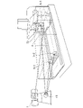
- FIG. 1 is a diagram showing an example of how a position measuring device 1 according to the present embodiment measures the position of an object to be measured.
- the object to be measured is the robot T1 as an example.
- the robot T1 has a movable part.
- the movable part is provided with a tip for processing the material.
- the tip is provided with an optical processing head.
- the position measuring device 1 irradiates measuring light onto the reflecting element 4 arranged on the movable part to be measured, and receives the reflected light.
- the position measuring device 1 measures position information based on the received light result.
- the positional information is information indicating the position of the reflecting element 4 with respect to the reference position.
- the reference position is a predetermined position in space where the reflective element 4 is arranged.
- the position information is indicated by the coordinates of a coordinate system (referred to as a reference coordinate system) within the space in which the reflective element 4 is arranged.
- the position information is indicated, for example, by Cartesian coordinates (X, Y, Z).
- a set of coordinates X, Y, and Z indicates a position in Cartesian coordinates (X, Y, Z). Note that the coordinate X, the coordinate Y, and the coordinate Z may be called the distance in the X direction, the distance in the Y direction, and the distance in the Z direction, respectively.
- the position measuring device 1 transmits the measured position information to the machine tool or robot control system.
- the reference position and coordinate system are shared in advance between the position measuring device 1 and the control system. Since the control system can acquire the positions of the machine tools and robots based on the position information received from the position measuring device 1, the machine tools and robots can be calibrated with high accuracy.
- the position measuring device 1 irradiates measuring light onto the reflecting element 4 arranged on the movable part to be measured, and receives the reflected light. First, the position measuring device 1 calculates distance information based on the received light result. Distance information is information indicating the distance from the position measuring device 1 to the reflective element 4 .
- the position measuring device 1 acquires direction information based on the irradiation direction of the measurement light.
- Direction information is information indicating the direction of the reflective element 4 with respect to the reference direction.
- the reference direction is, for example, a direction in which the azimuth angle and elevation angle are set to zero in the position measuring device 1 . Alternatively, it may be a direction when a predetermined reference point is viewed from the position measuring device 1 .
- the directional information is indicated by a pair of azimuth and elevation (that is, the angular component of spherical coordinates).
- the position measuring device 1 calculates the relative position of the reflective element 4 with respect to the own device based on the acquired distance information and direction information.
- the position measuring device 1 determines the position of the reflective element 4 with respect to the reference position (that is, the position of the reflective element 4 in the reference coordinate system) based on the relative position of the reference position with respect to the self device and the relative position of the reflective element 4 with respect to the self device. ) is calculated as position information.
- the position information may be indicated by spherical coordinates, or may be indicated by another orthogonal coordinate system.
- An orthogonal coordinate system is a general term for coordinate systems in which unit vectors are orthogonal.
- Position is a physical quantity that indicates where an object is in space.
- a distance is a physical quantity indicating a length measured between two points in space. The distance is, for example, the Euclidean distance.
- FIG. 2 is a diagram showing an example of the configuration of the position measuring device 1 according to this embodiment.
- the position measuring device 1 includes a housing 10, an optical comb interferometer 11, a quadrant position sensitive detector (PSD) 12, a coaxial camera 13, a beam steering mirror 14, and a pointing mirror assembly.
- PMA quadrant position sensitive detector
- the housing 10 is a member for installing the main body of the position measuring device 1 on an installation target.
- the installation target is a factory floor or the like.
- the housing 10 fixes the position measuring device 1 to the installation target by its own load, for example.
- the housing 10 may include a mechanism for fixing the position measuring device 2 to an installation target.
- the housing 10 is equipped with each component of the position measuring device 1 .
- a beam steering mirror 14 and a PMA 15 are provided outside the housing 10 .
- an optical comb interferometer 11, a quadrant PSD 12, a coaxial camera 13, a first half mirror 16, and a second half mirror 17 are provided inside the housing 10.
- the housing 10 has a space inside for propagating the measurement light and the reflected light.
- the optical comb interferometer 11 measures the distance from itself to the measurement target.
- the optical comb interferometer 11 irradiates an optical comb as measurement light to the reflecting element 4 placed on the object to be measured.
- An optical comb is pulsed light in which spectral intensities are arranged in a comb-like shape precisely and at regular intervals on the frequency axis.
- the optical comb interferometer 11 receives reflected light generated by the reflection of the optical comb by the reflecting element 4 .
- the distance from the optical comb interferometer 11 to the reflective element 4 is measured based on the position of the interference fringes between different pulses of the optical comb.
- the optical comb interferometer 11 can measure the distance with an accuracy on the order of submicrometers, for example.
- the optical comb interferometer 11 includes an irradiation section, a light receiving section, and a signal processing section.
- the irradiation section includes a pulsed light source, a frequency control section, and the like.
- the irradiation unit irradiates the object to be measured with the pulsed light generated by the pulsed light source as measurement light. Further, the irradiating unit splits a portion of the pulsed light generated by the pulsed light source and irradiates the reference plane in the optical comb interferometer 11 with the branched light as reference light.
- the light receiver includes a photodetector. The photodetector detects the reflected light and the reference light applied to the reference surface. When the detection result by the photodetector is input, the signal processing unit calculates the distance from the optical comb interferometer 11 to the reflecting element 4 based on the position of the interference fringes between the reflected light and the reference light. .
- the measurement light emitted by the optical comb interferometer 11 is reflected by the beam steering mirror 14 after passing through the first half mirror 16 and the second half mirror 17 to irradiate the reflecting element 4 .
- the optical path of the measurement light irradiated to the reflecting element 4 and the reflected light reflected by the reflecting element 4 are partly common.
- the coaxial camera 13 captures an image of the reflective element 4 that is the object to be measured.
- the coaxial camera 13 captures an image of the reflecting element 4 using reflected light of natural light reflected by the reflecting element 4 .
- a coaxial camera 13 is used to capture the position of the reflective element 4 .
- the coaxial camera 13 picks up the image of the reflecting element 4 so that the position measuring device 1 roughly grasps the position of the reflecting element 4 and adjusts the direction of irradiation of the measurement light.
- Image A ⁇ b>1 is an example of an image of reflecting element 4 captured by coaxial camera 13 .
- the imaging center of the coaxial camera 13 is adjusted to match the optical axis of the measurement light of the optical comb interferometer 11 . Therefore, the small circle in the center of the image A1 is the position of the measurement light, and the incident position on the reflecting element 4 can be detected.
- the quadrant PSD 12 detects the incident position of the reflected light on the light receiving section by detecting the reflected light from the reflecting element 4 .
- the reflected light is the reflected light obtained by reflecting the measurement light emitted from the optical comb interferometer 11 by the reflecting element 4 .
- Part of the reflected light is reflected by the first half mirror 16 and enters the quadrant PSD 12 .
- the quadrant PSD 12 includes, for example, photodiodes and resistors.
- the photodiodes are arranged in an array. That is, the quadrant PSD 12 includes a photodiode array.
- the quadrant PSD 12 has a detection surface divided into four.
- the 4-split PSD 12 measures the position of the spot light based on the light amount of the spot light of the reflected light detected on each of the four split detection surfaces. Therefore, the quadrant PSD 12 is a photoelectric detection device that detects the amount of reflected light.
- the quadrant PSD 12 is an example of a reflected light detection section.
- the quadrant PSD 12 finely adjusts the direction in which the measurement light is emitted so that the reflected light appropriately returns (enters) the optical comb interferometer 11.
- the position measuring device 1 may be provided with another position detector instead of the quadrant PSD 12 .
- Other position detectors are, for example, line sensors, phase detection type distance measuring instruments, and the like.
- the coaxial camera 13 is provided as an imaging section different from the reflected light detection section, but is not limited to this.
- the quadrant PSD 12 may be omitted from the configuration of the position measuring device 1, and the coaxial camera 13 may be used as the reflected light detector.
- the beam steering mirror 14 reflects the measurement light emitted from the optical comb interferometer 11 toward the reflecting element 4 . Also, the beam steering mirror 14 reflects the reflected light, which is the measurement light reflected from the reflecting element 4 , toward the optical comb interferometer 11 .
- the PMA 15 moves (changes) the direction of the beam steering mirror 14 .
- the PMA 15 includes, for example, a gimbal section and a rotary encoder (not shown).
- the orientation of the beam steering mirror 14 is changed by driving the gimbal section.
- the gimbal section can rotate the beam steering mirror 14 in each of the longitudinal direction (azimuth direction) and the latitudinal direction (elevation direction).
- a rotary encoder measures the rotation angle of the gimbal section.
- the optical path of the reflected light used for imaging by the coaxial camera 13 described above and the optical path of the measurement light or reflected light used by the optical comb interferometer 11 described above for distance measurement are partly common.
- the optical path of at least a part of the optical system for imaging by the first imaging section 23 is common to the optical path of at least a part of the optical system for light reception by the light receiving section provided in the optical comb interferometer 11 .
- the irradiation direction of the measurement light and the imaging direction of the coaxial camera 13 are coaxial.
- the imaging direction of the coaxial camera 13 is changed by changing the orientation of the beam steering mirror 14 that changes the direction of the measurement light emitted by the optical comb interferometer 11 . That is, the beam steering mirror 14 is commonly used for changing the irradiation direction of the measurement light emitted by the optical comb interferometer 11 and for changing the imaging direction of the coaxial camera 13 .
- the position measuring device 1 may include a camera outside the housing 10 instead of or in addition to the coaxial camera 13 .
- the optical path of the reflected light used for imaging and the optical path of the measurement light or the reflected light used by the above-described optical comb interferometer 11 for distance measurement are not common.
- a driving mechanism is provided for changing the imaging direction of the camera.
- the camera may be, for example, a wide-angle camera capable of imaging the surroundings of the position measuring device 1 .
- the first half mirror 16 transmits the measurement light emitted from the optical comb interferometer 11 .
- the first half mirror 16 transmits a portion of the reflected light of the measurement light reflected by the reflecting element 4 toward the optical comb interferometer 11 and reflects the remaining portion toward the quadrant PSD 12 .
- the second half mirror 17 transmits the measurement light emitted from the optical comb interferometer 11 . Also, the second half mirror 17 transmits part of the reflected light of the measuring light reflected by the reflecting element 4 toward the optical comb interferometer 11 . Also, the second half mirror 17 reflects the reflected light, which is the natural light reflected from the reflecting element 4 , toward the coaxial camera 13 .
- the reflective element 4 is placed on the object to be measured.
- the reflective element 4 is arranged on a movable part to be measured, such as a machine tool or a robot.
- Reflective element 4 is, for example, a retroreflector.
- a retroreflector is an optical element that reflects a beam in the direction of incidence, regardless of the position or direction in which the beam entered the retroreflector. That is, the retroreflector has a retroreflective function.
- the reference measurement light irradiation unit 19 is provided as part of the optical comb interferometer 11 .
- the reference measurement light irradiation section 19 includes a first reference irradiation section, a second reference irradiation section, and a third reference irradiation section.
- the position measuring device 1 includes an optical system inside the housing 10 for branching the measurement light emitted from the optical comb interferometer 11 .
- the optical system can split the measurement light into eight at maximum.
- the first reference measurement light, the second reference measurement light, and the third reference measurement light emitted by the reference measurement light irradiation unit 19 are light beams branched from the measurement light emitted from the optical comb interferometer 11. is. That is, the measuring light of the distance measuring section 200 and the reference measuring light of the reference distance measuring section 210 are branched and supplied from the same light source.
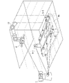
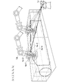
- FIG. 3 is a diagram showing an example of how the position measuring device 1 according to this embodiment performs measurement.
- the object to be measured is, for example, a movable part of a machine tool.
- the reflective element 4 is arranged on the movable part T2 of the machine tool. That is, the reflective element 4 is provided on the movable measurement object.
- the machine tool has a machining head, and the machining head has an end effector such as an end mill.
- the movable part T2 of the machine tool is, for example, a mechanism for changing the angle and position of the end mill to desired angles and positions.
- the reference reflecting element 5 is composed of three reference reflecting elements 5-1, 5-2, and 3rd reference reflecting element 5-3.
- the first reference reflective element 5-1, the second reference reflective element 5-2, and the third reference reflective element 5-3 are a surface plate on which an object to be machined by the machine tool is placed. placed above. That is, the reference reflecting element 5 is provided on a measurement reference object different from the measuring object on which the reflecting element 4 is provided.
- a three-dimensional coordinate system (reference coordinate system) and a reference are set with reference to the positions of the plurality of reference reflecting elements 5 .
- the position of the origin of the three-dimensional coordinate system is, for example, the position of any one of the multiple reference reflecting elements 5 .
- the details of setting the reference coordinate system and the reference (origin) will be described later.
- the first reference reflective element 5-1, the second reference reflective element 5-2, and the third reference reflective element 5-3 may be collectively referred to as a plurality of reference reflective elements 5.
- Each of the plurality of reference reflecting elements 5 is a retroreflector. In other words, each of the plurality of reference reflecting elements 5 has a retroreflecting function like the reflecting element 4 does.
- FIG. 4 is a diagram showing an example of the functional configuration of the position measuring device 1 according to this embodiment.
- the position measurement device 1 includes a position measurement section 20, a reference position measurement section 21, a control section 22, a first imaging section 23, a reflected light detection section 24, a communication section 25, and a calculation section 26. .
- the position measuring unit 20 includes a distance measuring unit 200 , an irradiation direction moving unit 201 , an irradiation direction measuring unit 202 and a position information acquiring unit 203 .
- the distance measuring unit 200 irradiates the reflecting element 4 with measurement light, receives the reflected light, and measures the distance to the reflecting element.
- Distance measurement section 200 includes an irradiation section, a light receiving section, and a signal processing section.
- the irradiating section irradiates the reflecting element arranged on the movable section to be measured with the measurement light.
- the light receiving section receives the reflected light.
- the signal processing section processes the signal from the light receiving section and obtains distance information to the reflecting element 4 .
- Distance measuring section 200 includes optical comb interferometer 11 .
- the irradiation unit includes a pulsed light source provided in the optical comb interferometer 11 .
- the light receiving section includes a light receiving section provided in the optical comb interferometer 11 .
- the signal processing section includes a signal processing section provided in the optical comb interferometer 11 .
- the irradiation direction moving unit 201 changes the irradiation direction of the measurement light. Changing the irradiation direction is also referred to as moving the irradiation direction.
- the irradiation direction moving unit 201 moves the irradiation direction according to the movement of the reflected light detected by the reflected light detection unit 24 .
- the irradiation direction moving section 201 includes a gimbal section included in the PMA 15 .
- the beam steering mirror 14 is commonly used for changing the irradiation direction of the measurement light emitted by the optical comb interferometer 11 and for changing the imaging direction of the coaxial camera 13.
- the irradiation direction moving unit 201 includes an imaging adjustment unit.
- the imaging adjustment section adjusts the imaging direction of the first imaging section 23 . Therefore, the irradiation direction moving unit 201 simultaneously moves the irradiation direction of the measurement light and the imaging direction of the first imaging unit 23 .
- the irradiation direction measuring unit 202 measures the irradiation direction of the measurement light.
- the irradiation direction measurement unit 202 includes a rotary encoder included in the PMA 15.
- FIG. The irradiation direction measurement unit 202 outputs the measurement result of the irradiation direction to the position information acquisition unit 203 of the distance measurement unit 200 as direction information.
- the position information acquisition unit 203 determines the position of the reflection element 4 based on the distance (distance information) to the reflection element 4 measured by the distance measurement unit 200 and the irradiation direction (direction information) of the measurement light measured by the irradiation direction measurement unit 202. Acquire the position (position information) in the three-dimensional space. The details of acquisition of position information will be described later.
- the reference position measuring section 21 is composed of three parts: a reference position measuring section 21-1, a reference position measuring section 21-2, and a reference position measuring section 21-3.
- the reference position measuring section 21-1, the reference position measuring section 21-2, and the reference position measuring section 21-3 may be collectively referred to as the reference position measuring section 21.
- the reference position measurement unit 21-1 includes a reference distance measurement unit 210-1, a reference irradiation direction movement unit 211-1, a reference irradiation direction measurement unit 212-1, and a reference position information acquisition unit 213-1.
- the reference distance measuring unit 210-1 irradiates the first reference reflecting element 5-1 with the reference measuring light, receives the reference reflected light, and measures the distance to the first reference reflecting element 5-1.
- Reference distance measurement section 210-1 includes a first reference irradiation section, a first reference light receiving section, and a first reference signal processing section.
- the first reference irradiator irradiates the first reference reflection element 5-1 with the first reference measurement light.
- the first reference irradiation section includes an optical system for branching the measurement light emitted from the optical comb interferometer 11 .
- the first reference light receiving section receives the first reference reflected light from the first reference reflecting element 5-1.
- a light-receiving unit provided inside the housing 10 of the position measuring device 1 is included.
- the first reference signal processing section processes the signal from the first reference light receiving section and acquires the first reference distance information.
- the first reference distance information is information indicating the distance from the position measuring device 1 to the first reference reflecting element 5-1.
- the reference irradiation direction moving unit 211-1 changes the irradiation direction of the reference measurement light. Changing the irradiation direction is also referred to as moving the irradiation direction.
- the reference irradiation direction moving section 211-1 includes a gimbal section included in the PMA 15.
- the reference irradiation direction measurement unit 212-1 measures the irradiation direction of the reference measurement light.
- the reference position information acquisition unit 213-1 obtains the distance (distance information) to the first reference reflecting element 5-1 measured by the reference distance measurement unit 210 and the reference measurement light measured by the reference irradiation direction measurement unit 212-1.
- the position of the first reference reflecting element 5-1 in the three-dimensional space is acquired from the irradiation direction (direction information). Details of acquisition of the reference position information will be described later.
- the reference position measurement unit 21-2 irradiates the second reference reflection element 5-2 with the reference measurement light, receives the reference reflected light, and measures the position of the second reference reflection element 5-2.
- the reference position measuring section 21-3 irradiates the third reference reflecting element 5-3 with the reference measuring light, receives the reference reflected light, and measures the position of the third reference reflecting element 5-3. Since the functional configuration of the reference position measuring section 21-2 and the reference position measuring section 21-3 is the same as that of the reference position measuring section 21-1, detailed description thereof will be omitted.
- reference distance measuring section 210-1, reference distance measuring section 210-2, and reference distance measuring section 210-3 may be simply referred to as reference distance measuring section 210 in some cases.
- Reference distance measurement section 210-1, reference distance measurement section 210-2, and reference distance measurement section 210-3 may be collectively referred to as a plurality of reference distance measurement sections 210 in some cases.
- any one of the reference irradiation direction moving unit 211-1, the reference irradiation direction moving unit 211-2, and the reference irradiation direction moving unit 211-3 may be simply referred to as the reference irradiation direction moving unit 211 in some cases.
- the reference irradiation direction moving unit 211-1, the reference irradiation direction moving unit 211-2, and the reference irradiation direction moving unit 211-3 may be collectively referred to as a plurality of reference irradiation direction moving units 211 in some cases.
- any one of the reference irradiation direction measuring section 212-1, the reference irradiation direction measuring section 212-2, and the reference irradiation direction measuring section 212-3 may be simply referred to as the reference irradiation direction measuring section 212 in some cases.
- the reference irradiation direction measuring unit 212-1, the reference irradiation direction measuring unit 212-2, and the reference irradiation direction measuring unit 212-3 may be collectively referred to as a plurality of reference irradiation direction measuring units 212 in some cases.
- any one of the reference position information acquisition section 213-1, the reference position information acquisition section 213-2, and the reference position information acquisition section 213-3 may be simply referred to as the reference position information acquisition section 213 in some cases.
- the reference position information acquisition section 213-1, the reference position information acquisition section 213-2, and the reference position information acquisition section 213-3 may be collectively referred to as a plurality of reference position information acquisition sections 213 in some cases.
- the control unit 22 controls each device and parts provided in the position measuring device 2 .
- the control unit 22 includes, for example, a CPU (Central Processing Unit), GPU (Graphics Processing Unit), FPGA (field-programmable gate array), etc., and performs various calculations and exchanges of information.
- the control unit 22 reads programs from the ROM and executes various controls according to the read programs.
- control unit 22 and other devices and parts provided in the position measuring device 1 are connected by signal lines, for example.
- control unit 22 and each device and part provided in the position measuring device 2 may communicate with each other by short-range wireless communication.
- the control unit 22 causes the calculation unit 26 to execute part of various calculations.
- the control unit 22 also includes an imaging adjustment unit.
- the calculation unit 26 includes a reference coordinate setting unit 260 and a first correction unit 261 .
- the reference coordinate setting unit 260 sets the reference (origin) and reference coordinate system based on the first reference position information, the second reference position information, and the third reference position information.
- the first correction unit 261 acquires position information of the reflective element 4 with respect to the reference generated by the reference coordinate setting unit 260 .
- the positional information of the reflective element 4 with respect to the reference includes the positional information of the reflective element 4 in the set reference coordinate system.
- the first corrector 261 further corrects variations in the positional information of the reflective element 4 with respect to the reference.
- the first imaging section 23 captures an image of the reflecting element 4 .
- First imaging unit 23 includes coaxial camera 13 .
- the reflected light detector 24 detects reflected light from the reflecting element 4 .
- the reflected light detector 24 detects the movement of the reflected light that moves with the movement of the reflecting element 4 .
- the reflected light detection section 24 includes a quadrant PSD 12 .
- the communication unit 25 communicates with external devices.
- the external device is, for example, a control system that controls the robot on which the reflecting element 4 is installed.
- Communication unit 25 includes a transmitter and a receiver.
- the transmission section transmits the position information of the reflecting element 4 acquired by the position information acquisition section included in the distance measurement section 200 to the control system.
- the communication unit 25 includes a communication interface (I/F) for communicating via a wireless network.
- a fifth generation mobile communication system or a mobile communication system using light with a shorter wavelength than millimeter waves may be used.
- the fifth generation mobile communication system uses a frequency band from 450 Mhz to 6000 Mhz and a frequency band from 24250 Mhz to 52600 Mhz.
- FIG. 5 is a diagram showing an example of position measurement processing according to the present embodiment. Position measurement processing is executed by the control unit 22 .
- the position measurement unit 20 acquires the position information of the reflective element 4 (step S10).
- the process of acquiring the position information of the reflecting element 4 is called position measurement process.
- the position measurement unit 20 irradiates the reflecting element 4 with measurement light, receives the reflected light reflected by the reflecting element 4 , and obtains the positional information of the reflecting element 4 in the three-dimensional space.
- FIG. 6 is a diagram showing an example of position information acquisition processing according to the present embodiment.
- the control unit 22 captures an image of the reflective element 4 using the first imaging unit 23 (step S110). Note that the control unit 22 may use the first imaging unit 23 to capture an image of at least a portion of the robot to be measured and/or the reflecting element 4 .
- the imaging adjustment section provided in the control section 22 adjusts the imaging direction of the first imaging section 23 so that the reflective element 4 is included in the imaging range of the first imaging section 23 .
- the imaging direction is, for example, the direction in which the optical axis of the imaging lens faces.
- the imaging adjustment unit may adjust the imaging direction of the first imaging unit 23 so that the direction in which the optical axis of the imaging lens faces overlaps with the reflecting element 4, or is included in the imaging range even if it does not overlap.
- the imaging adjustment section determines whether or not the reflective element 4 is included in the imaging range of the first imaging section 23 based on the image that is the imaging result of the first imaging section 23 .
- the imaging adjustment section has an image analysis function, and determines the image of the reflecting element 4 by analyzing the imaging result of the first imaging section 23 .
- the imaging adjustment unit determines the image of the reflecting element 4 based on pattern matching, for example.
- the irradiation direction moving unit 201 may learn the image of the reflecting element 4 in advance by AI (machine learning) and determine the image of the reflecting element 4 based on the learning result.
- the position where the position measuring device 1 is installed and/or the orientation of the housing 10 is adjusted in advance so that the reflecting element 4 is included in the imaging range of the first imaging unit 23.
- the imaging adjustment section may be omitted from the configuration of the control section 22 .
- the control unit 22 controls the irradiation direction moving unit 201 so that the reflection element 4 is irradiated with the measurement light based on the imaging result of the first imaging unit 23 (step S120).
- the irradiation direction moving unit 201 changes the direction of the beam steering mirror 14 using the measurement result of the irradiation direction by the rotary encoder.
- the irradiation direction moving unit 201 changes the orientation of the beam steering mirror 14 in the longitudinal direction and/or the latitudinal direction via the gimbal unit.
- the irradiation direction moving unit 201 moves the irradiation direction according to the command of the control unit 22 so that the measurement light is irradiated to the reflecting element 4 to be measured determined based on the imaging result of the first imaging unit 23. .
- control unit 22 controls the irradiation direction moving unit 201 so that the measurement light follows the movement of the reflective element 4 to be measured based on the imaging result of the first imaging unit 23 . Since the irradiation direction moving unit 201 is driven so that the measuring light follows the reflecting element 4, even when the reflecting element 4 moves, the measuring light continues to irradiate the reflecting element 4, and the first imaging unit 23 The reflective element 4 can continue to be imaged.
- the imaging adjustment unit In the process of following the reflective element 4 by the irradiation direction moving unit 201, the imaging adjustment unit repeatedly executes image analysis to determine and capture the image of the reflective element 4 at each time.
- the measuring light from the optical comb interferometer 11 included in the distance measuring unit 200 is irradiated toward the reflecting element 4 (step S130).
- the reflected light is reflected by total internal reflection.
- the reflective element 4 may not be an element that performs total reflection.
- a corner cube reflector may be used as the reflecting element 4 .
- the cube-corner reflector may be a cube-corner reflective element with a reflection-enhancing coating.
- a ball reflector or a cat's eye may be used as the reflecting element 4 .
- the reflected light from the reflecting element 4 passes through the same path as the measurement light in the opposite direction, and is received by the light receiving section of the distance measuring section 200 including the optical comb interferometer 11 (step S140). Also, part of the reflected light is detected by the quadrant PSD 12 .
- the control unit 22 again controls the irradiation direction moving unit 201 so that the measurement light continues to irradiate the reflecting element 4 based on the detection result by the quadrant PSD 12 .
- the control unit 22 finely adjusts the irradiation direction of the measurement light by the irradiation direction moving unit 201 based on the detection result by the 4-divided PSD 12 .
- the sub-micrometer Measurements can be continued with an accuracy of the order of magnitude.
- the position information acquisition unit 203 acquires the position information of the reflecting element 4 from the detection result (distance information) by the distance measurement unit 200 including the optical comb interferometer 11 and the direction information measured by the irradiation direction measurement unit 202 (step S150).
- the acquired position information is output to the calculation section 26 via the control section 22 .
- the position information is represented by three-dimensional spherical coordinates with the position measuring device 1 as a reference.
- the position measuring unit 20 uses the distance (distance information) to the reflecting element 4 measured by the distance measuring unit 200 and the irradiation direction (direction information) measured by the irradiation direction measuring unit 202 to Positional information of the element 4 in the three-dimensional space is obtained.
- the reference position measurement unit 21 acquires reference position information of the reference reflecting element 5 (step S20).
- the reference position measurement unit 21 irradiates at least one reference reflection element 5 with reference measurement light, receives the reference reflected light reflected by the reference reflection element 5, and obtains position information of the reference reflection element 5 in the three-dimensional space.
- Acquire reference position information
- the position measuring device 1 includes a plurality of reference position measuring units 21 .
- a plurality of reference reflective elements 5 acquire position information of different reference reflective elements 5 .
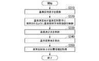
- FIG. 7 is a diagram showing an example of reference position information generation processing according to the present embodiment.
- the processing from step S310 to step S350 shown in FIG. 7 is executed as the processing of step S20 shown in FIG. Note that the processing from step S310 to step S350 shown in FIG. 7 may be executed at the start of measurement.
- the control unit 22 uses the first imaging unit 23 to capture images of the plurality of reference reflecting elements 5 (step S310).
- the control unit 22 controls each of the plurality of reference irradiation direction moving units 211 so that each of the three reference measurement lights is irradiated onto each of the plurality of reference reflecting elements 5 (step S320).
- the control unit 22 uses the imaging result of the images of the plurality of reference reflecting elements 5 by the first imaging unit 23 in the control of step S320.
- the control unit 22 controls the reference irradiation direction moving unit 211 so that each of the plurality of reference reflecting elements 5 is irradiated with the plurality of reference measurement lights. (Step S330).
- the control unit 22 may cause each of the plurality of reference irradiation units to irradiate the reference measurement light simultaneously or sequentially.
- the reflected light from the reference reflecting element 5 passes through the same path as the reference measurement light in the opposite direction, and is received by the reference light receiving section provided in the reference distance measuring section 210 . (Step S340).
- the reference position information acquisition unit 213 acquires reference position information of the reference reflecting element 5 from the measurement result (reference distance information) by the reference distance measurement unit 210 and the reference irradiation direction information acquired by the reference irradiation direction measurement unit 212 (step S350).
- the reference position generation processing described here is performed in each of the reference position measuring section 21-1, the reference position measuring section 21-2, and the reference position measuring section 21-3, and the first reference position information, Second reference position information and third reference position information are obtained.
- the acquired first, second, and third reference position information are output to the calculation section 26 via the control section 22 .
- the reference position information is represented by three-dimensional spherical coordinates with the position measuring device 1 as a reference.
- the reference position measurement unit 21 calculates the reference reflection from the distance to the reference reflecting element 5 measured by the reference distance measurement unit 210 and the irradiation direction of the reference measurement light measured by the reference irradiation direction measurement unit 212. Position information of the element 5 in the three-dimensional space is obtained.
- a reference coordinate setting unit 260 included in the calculation unit 26 sets a reference (origin) and A reference coordinate system is set (step S30).
- the reference coordinate setting unit 260 sets a desired orthogonal coordinate system (reference coordinate system) based on these three pieces of reference position information. set.
- the measurement object moves according to the installation positions of the first reference reflection element 5-1, the second reference reflection element 5-2, and the third reference reflection element 5-3. It can be set arbitrarily in the space.
- the space in which the movable part T2 which is the object to be measured moves includes two axes parallel to the surface of the platen on which the object to be measured is placed.
- a Cartesian coordinate system can be set.
- the reference coordinate setting unit 260 sets the origin as a reference within the reference coordinate system. The origin may be any of the three reference reflecting elements 5-1, 5-2 and 5-3 (reference positions).
- the movable part T2 (and thus the reflective element 4), which is the object to be measured, is positioned at a predetermined position in the reference coordinate system, for example, the origin of the movable part T2 determined by the machine tool, and the position information of the reflective element 4 at that time and the reference You may match the origin in a coordinate system.
- the position information acquired by the position measuring unit 20 and the position information acquired by the reference position measuring unit 21 are regarded as the same position information, and the position information acquired by the position measuring unit 20 and the reference position are obtained.
- a deviation from the position information acquired by the measurement unit 21 can be eliminated (corrected).
- the reference coordinate system and the reference are set based on the reference position information obtained from the reference reflecting element.
- the first correction unit 261 included in the calculation unit 26 converts the positional information of the reflecting element 4 into positional information in the reference coordinate system (step S40).
- the first correction unit 261 converts the position information of the reflecting element 4 measured by the position measurement unit 20 from the three-dimensional spherical coordinates with the position measurement device 1 as a reference to the orthogonal coordinates in the reference coordinate system set by the reference coordinate setting unit 260. Convert to Thereby, in the space in which the measurement object moves, the positional information of the measurement object (that is, the positional information of the reflective element 4) can be acquired in orthogonal coordinates in the reference coordinate system.
- the relative positional relationship between the position measuring device 1 and the object to be measured may fluctuate due to vibration of the floor, vibration caused by the operation of the robot, etc., regardless of the movement of the object to be measured. .
- the first correction unit 261 corrects the position information of the reflecting element 4 using the reference position information of the reference reflecting element 5 (step S50).
- the correction may include resetting the reference (origin) and the reference coordinate system set in step S30.
- the same operation as in step S30 may be performed at regular time intervals or irregularly to acquire the deviation of the reference coordinate system and correct the deviation.
- variations in the origin over time can be calibrated (origin calibration).
- the reference position information of the reference reflecting element 5 may be constantly acquired, and fluctuations of the reference (origin) and the reference coordinate system may be constantly corrected. In this case, short-term fluctuations (vibrations) can also be corrected.
- the reference reflecting element 5 is installed on a measurement reference object that serves as a reference for position measurement of the measurement object, and the reference coordinate system and the origin are set based on the reference position information of the reference reflecting element 5 acquired by the position measuring device 1.
- the conversion of the positional information of the reflecting element 4 into the positional information in the reference coordinate system executed by the first correction unit 261 can also be said to be correction of the positional information of the reflecting element 4 .
- the control unit 22 transmits the corrected position information to the control system (step S60). With this, the control unit 22 ends the position measurement process.
- FIG. 8 is a diagram showing an example of how the position measuring device 1 according to this modification measures the reference position.
- the position-measuring device 1 is arranged in a processing device equipped with a robot T3.
- the robot T3 processes the work W1 placed in the processing device.
- the first reference reflective element 5-1, the second reference reflective element 5-2, and the third reference reflective element 5-3 are arranged on the workpiece W1.
- the work W1 is a large work having sufficiently high rigidity. If the work is a large work with sufficiently high rigidity like the work W1, the reference reflecting element 5 may be arranged on the work as in this modification.
- the robot T3 may vibrate the position measuring device 1 through the housing of the processing device. Further, even when the position measuring device 1 is installed on the floor, the position measuring device 1 may be vibrated during the process of the robot T3 processing the workpiece W1. Therefore, the position measuring device 1 is preferably installed in a vibration-isolated and/or damped state. If the position measuring device 1 is vibration-isolated and/or damped, the position measuring device 1 and the workpiece W1 can be regarded as rigid bodies.
- the temperature and atmospheric pressure of the environment can fluctuate over time. Fluctuations in temperature and air pressure cause variations in the refractive index. Since the position measuring device 1 acquires the position information by the optical comb interferometer 11, the refractive index fluctuations can become an error in the fluctuation of the position information of the reflective elements.
- FIG. 9 is a diagram showing an example of how the position measuring device 1 according to this modification uses the reference light R1 to correct errors in position information due to refractive index fluctuations.
- a reference reflecting element 5-4 is arranged on a surface plate together with a first reference reflecting element 5-1, a second reference reflecting element 5-2, and a third reference reflecting element 5-3.
- the reference reflective element 5-4 has the same position as the first reference reflective element 5-1, the second reference reflective element 5-2, and the third reference reflective element 5-3, except that the arrangement position is different. It has the same configuration as each of the element 5-1, the second reference reflective element 5-2, and the third reference reflective element 5-3.
- the position measuring device 1 irradiates the reference reflection element 5-4 with the reference light R1 from the reference measurement light irradiation unit 19.
- one of the first reference irradiation section, the second reference irradiation section, and the third reference irradiation section provided in the reference measurement light irradiation section 19 emits the reference measurement light as the reference light R1.
- the first reference irradiation unit irradiates the reference beam R1.
- the reference measurement light irradiation section 19 may include a reference light irradiation section that emits the reference light R1 separately from the first reference irradiation section, the second reference irradiation section, and the third reference irradiation section.
- the reference light irradiator uses light obtained by branching the measurement light emitted from the optical comb interferometer 11 as the reference light R1.
- the position measuring device 1 includes a pulsed light source for irradiating the reference light R1 separately from the pulsed light source provided in the optical comb interferometer 11, and the reference light irradiator emits light from the pulsed light source for irradiating the reference light R1.
- the pulsed light thus obtained may be irradiated as the reference light R1.
- the position measuring device 1 operates under a predetermined environment (which may be referred to as a reference environment in the following description) in advance, based on the reference light R1 that irradiates the reference reflecting element 5-4, from the position measuring device 1 to the reference reflecting element. Acquire distance information up to 5-4.
- a predetermined environment is an environment represented by the temperature and pressure of the space in which the reference reflecting element 5-4 is arranged. The acquired distance information varies depending on the environment.
- the reference reflecting element 5-4 is arranged on the surface plate in this modified example 2, the reflecting element 4, the first reference reflecting element 5-1, the second reference reflecting element 5-2, and the third reference reflecting element
- the device 5-3 may be placed anywhere as long as it represents the environment (temperature, atmospheric pressure, etc.) in which the device 5-3 is installed.
- the position measuring device 1 measures the position information of the reflecting element 4 simultaneously with measuring the position information of the reflecting element 4 in an environment for measuring the position information of the reflecting element 4 (in the following description, it may be referred to as a measurement environment).
- Distance information from the device 1 to the reference reflecting element 5-4 is obtained.
- the distance between the position measuring device 1 and the reference reflecting element 5-4 is known.
- the position measuring device 1 compares distance information acquired in the measurement environment with known distance information to the reference reflecting element 5-4, and calculates a ratio (correction coefficient) between the two.
- the position measuring device 1 multiplies the acquired position information of the reflecting element 4 by a correction coefficient to correct the position information. As a result, the position measuring device 1 corrects an error in the position information due to the refractive index variation.
- the first reference irradiating unit irradiates the reference reflecting element 5-4 with the reference light R1 and compares it with a known distance, but it is not limited to this.
- a reference reflecting element 5-5 is provided separately from the reference reflecting element 5-4, and the first reference irradiation unit sequentially irradiates the reference term R1 to the reference reflecting element 5-4 and the reference reflecting element 5-5, and the position Get information.
- the relative positional relationship between the reference reflecting element 5-4 and the reference reflecting element 5-5 is known. Accordingly, the correction coefficient can be calculated from the known relative positional relationship and the measured positional relationship between the reference reflecting elements 5-4 and 5-5. Any one or two of the first reference reflecting element 5-1, the second reference reflecting element 5-2, and the third reference reflecting element 5-3 are used instead of the reference reflecting elements 5-4 and 5-5. It may be used for correction coefficient calculation.
- the position measuring device 1 corrects the position information of the reflecting element 4 measured by the position measuring section 20 using the position information of the reference reflecting element 5 acquired by the reference position measuring section 21. do.
- the correction includes correcting variations in the positional information of the reflective element 4 over time.
- the correction is performed by correcting an error in the position information of the reflecting element 4 caused by the temperature and atmospheric pressure of the space in which the reflecting element 4 and the reference reflecting element 5 are arranged to the position of the reference reflecting element 5 acquired by the reference position measuring unit 21. Including making informed corrections.
- the position measuring device 1 may acquire position information of a robot arm provided in a coordinate measuring machine (CMM).
- CMM coordinate measuring machine
- the reflective element 4 is provided on the movable part of the robot arm.
- a reference reflective element 5 is provided, for example, on the floor of the CMM.
- the CMM floor is a different part of the CMM configuration than the robot arm.
- the robot arm and the floor of the CMM make up the CMM.
- the object to be measured and the reference object form one device.
- the position measuring device 1 determines a device coordinate system that serves as a reference for the positional information of the object to be measured in the one device based on the positional information of the reference reflecting element 5 acquired by the reference position measuring unit 21.
- the position measuring device 1 can calibrate or correct the device coordinate system of the three-dimensional measuring machine itself, which is one device.
- the position measuring device 1 includes the position measuring section 20 and the reference position measuring section 21 .
- the position measurement unit 20 irradiates the reflecting element 4 with measurement light, receives the reflected light reflected by the reflecting element 4 , and obtains the positional information of the reflecting element 4 in the three-dimensional space.
- the reference position measurement unit 21 irradiates at least one reference reflection element 5 with reference measurement light, receives the reference reflected light reflected by the reference reflection element 5, and obtains position information of the reference reflection element 5 in the three-dimensional space. to get
- the position measuring device 1 corrects the position information of the reflecting element 4 measured by the position measuring section 20 using the position information of the reference reflecting element 5 acquired by the reference position measuring section 21 .
- the position measuring device 1 can correct the position information of the reflecting element 4 using the position information of the reference reflecting element 5. Accuracy can be improved.
- the position measuring device 1 in controlling the robot, can measure the position information of the reflective element 4 installed on the robot and correct the position information, thereby measuring the position of the robot with high accuracy.
- the position measuring device 1 includes a first position measuring section (the position measuring section 20 in the present embodiment), a second position measuring section (the reference position measuring section in the present embodiment). 21) and The first position measuring unit (position measuring unit 20 in this embodiment) irradiates the reflecting element 4 with the first measurement light (measurement light in this embodiment), and the first reflected light reflected by the reflecting element 4 a first position measurement unit (position measurement unit 20 in this embodiment) that receives (in this embodiment, reflected light) and obtains positional information of the reflecting element 4 in the three-dimensional space; The second position measuring unit (reference position measuring unit 21 in this embodiment) irradiates the reflecting element with the second measuring light (reference measuring light in this embodiment), and the second reflected light reflected by the reflecting element 4 Light (reference reflected light in this embodiment) is received to acquire positional information of the reflecting element 4 in the three-dimensional space.
- the first position measuring unit irradiates the reflecting element 4 with the first measurement light (measurement light in this embodiment), and the first reflected light
- the position measuring device 1 can acquire the position information of the reflecting element 4 in the three-dimensional space by irradiating the reflecting element 4 with the first measuring light and the second measuring light.
- the accuracy of the position information can be improved as compared with the case where only the first measurement light is used.
- FIG. 10 is a diagram showing an example of the functional configuration of the position measuring device 1a according to this embodiment.
- the position measurement device 1a includes a position measurement unit 20, a reference position measurement unit 21, a control unit 22, a first imaging unit 23, a reflected light detection unit 24, a communication unit 25, a calculation unit 26a, and a storage unit. 27.
- the calculation unit 26 a includes a reference coordinate setting unit 260 , a first correction unit 261 , an incident information acquisition unit 262 and a second correction unit 263 .
- the incident information acquiring section 262 acquires incident information from the image of the reflecting element 4 captured by the first imaging section 23 .
- the incident information is information about the incident measurement light.
- the incident information includes the incident angle at which the measurement light is incident on the incident surface of the reflective element 4 .
- the incident information also includes the incident position within the incident surface of the reflecting element 4 where the measurement light is incident.
- the second correction section 263 corrects the position information acquired by the position measurement section 20 based on the incident information acquired by the incident information acquisition section 262 .
- the storage unit 27 stores various information.
- the measured value correction map 270 is stored in advance before the position measuring device 1a starts measurement.
- the measurement value correction map 270 is a set of the incident angle at which the measurement light is incident on the incident surface of the reflecting element 4, the incident position within the incident surface, and the correction amount corresponding to the error caused by the reflecting element 4. is associated information. Errors caused by the reflecting elements 4 are, for example, errors due to individual differences in manufacturing the reflecting elements 4 .
- the measured value correction map 270 may be stored in an external device such as a server. In that case, the incident information acquisition unit 262 acquires the measured value correction map 270 from the external device by communicating with the external device through the communication unit 25 . Alternatively, it may be stored in a storage area included in the second correction unit 263 .
- the optical path length difference is calculated by changing (shifting) the rotation center of the prism 41 provided in the reflecting element 4 .
- FIG. 11 is a diagram showing an example of a cross section of the prism 41 provided in the reflecting element 4 according to this embodiment.
- FIG. 11 shows a cross section when the height of the prism 41 is h1 and a cross section when the height of the prism 41 is h2.
- the height h2 is calculated by correcting the height h1 by the refractive index n of the prism based on the equation (1).
- Correcting the center of rotation of the prism 41 from the height h1 to the position of the height h2 is equivalent to converting the center of rotation of the prism 41 to a converted position converted into a value in air where no optical path length difference occurs. do.
- FIG. 12 is a diagram showing an example of the optical path length difference with respect to the incident angle according to this embodiment.
- FIG. 12 shows the optical path length difference with respect to the angle of incidence when the center of rotation of the prism 41 is at height h1 (without shift), and the difference in optical path length with respect to the angle of incidence when the center of rotation of prism 41 is at height h2 (with shift).
- the optical path length difference and the angle of incidence are shown, respectively.
- FIG. 13 shows a graph obtained by enlarging the graph shown in FIG. 12 with respect to the optical path length difference axis.
- FIG. 14 is a diagram showing an example of position measurement processing according to this embodiment. Position measurement processing is executed by the control unit 22 .
- the position measurement unit 20 acquires the position information of the reflective element 4 (step S410).
- the position measuring unit 20 irradiates the incident surface of the reflecting element 4 with measurement light, receives the reflected light, and acquires the position information of the reflecting element 4 in the three-dimensional space.
- the details of the position measurement process in step S410 are the same as the position measurement process in step S10 shown in FIG. 5, so description thereof will be omitted.
- the incident information acquisition unit 262 acquires incident information (step S420).
- the first imaging unit 23 images the reflection element 4 on which the measurement light is incident.
- the incident information acquisition section 262 acquires incident information from the image of the reflecting element 4 captured by the first imaging section 23 .
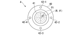
- FIG. 15 is a diagram showing an example of the front of the reflecting element 4 according to this embodiment.
- the reflective element 4 includes a holder portion 40 and a marker portion 42 .
- the marker section 42 is composed of a marker section 42-1, a marker section 42-2, a marker section 42-3, and a marker section 42-4.
- the holder portion 40 holds a prism 41 and a marker portion 42 .
- the shape of the holder portion 40 is concentric when viewed from the front.
- the marker part 42 is, for example, a light emitting diode (LED).
- the number of marker portions 42 is not limited to four, and may be any number of three or more under the condition that the marker portions 42 are not on the same straight line.
- the marker portion 42 may be provided on the holder portion 40 by coating a predetermined portion of the area of the holder portion 40 with paint instead of the LED.
- the color of the LED or the color of the paint may be any color as long as the area where the marker part 42 is provided in the holder part 40 can be distinguished from other areas.
- the marker portion 42 is not limited to a plurality of discrete points.
- the marker portion 42 can be a continuous or intermittent line, for example a circular luminous portion or coating surrounding the entrance surface of the reflective element 4 .
- the measuring light emitted from the position measuring device 1 is incident on the incident surface of the prism 41 provided in the reflecting element 4 at the position P1.
- Position P1 is shown using two-dimensional polar coordinates (R, ⁇ ) in the plane of incidence.
- FIG. 16 is a diagram showing an example of how the measurement light L1 is incident on the reflecting element 4 according to this embodiment.
- FIG. 16 shows respective cross sections of the holder portion 40 and the prism 41 provided in the reflecting element 4 .
- the measuring light L1 is incident on the prism 41 at an incident angle indicated by angles ( ⁇ , ⁇ ).
- the angles ⁇ and ⁇ are respectively the azimuth angle and the elevation angle on the plane of incidence when three-dimensional spherical coordinates are used.
- 17, 18, 19, and 20 respectively show a photographed image A11, a photographed image A12, a photographed image A13, and a photographed image A14 captured by the coaxial camera 13.
- images of the reflecting element 4 are captured when the measurement light is incident on the incident surface of the reflecting element 4 at different positions and angles.
- the imaging direction of the coaxial camera 13 matches the direction of the measurement light. Therefore, in the captured image captured by the coaxial camera 13, the image of the reflecting element 4 has a different shape depending on the incident angle on the incident surface of the measurement light.
- the incident information acquiring section 262 calculates the incident angle based on the shape of the incident surface in the image of the reflecting element 4 captured by the first imaging section 23 . Also, the incident position on the incident plane of the measurement light is acquired from the image. In this embodiment, since the imaging center of the coaxial camera 13 and the optical axis of the measurement light match, the position of the reflective element 4 is imaged differently depending on the incident position on the incident surface of the measurement light.
- the captured image A11 is a captured image captured by the coaxial camera 13 when the measurement light is incident from the front of the reflecting element 4 .
- the shape of the image of the reflecting element 4 is substantially circular.
- the captured image A12 is a captured image captured by the coaxial camera 13 when the measurement light is obliquely incident on the reflecting element 4 in the horizontal direction.
- the shape of the image of the reflecting element 4 is elliptical.
- a captured image A13 is a captured image captured by the coaxial camera 13 when the measurement light is incident from the front of the reflecting element 4 .
- the shape of the image of the reflecting element 4 is substantially circular as in the photographed image A11.
- the incident position of the measurement light differs between the captured image A13 and the captured image A11.
- a captured image A14 is a captured image captured by the coaxial camera 13 when the measurement light enters the reflecting element 4 obliquely in the vertical direction.
- the shape of the image of the reflecting element 4 is elliptical.
- the second corrector 263 corrects the position information of the reflecting element 4 based on the incident information (step S430).
- the second corrector 263 reads out the measured value correction map 270 from the memory 27 .
- the second correction unit 263 reads, from the measured value correction map 270 , the correction amount corresponding to the set of the incident angle and the incident position indicated by the incident information acquired by the incident information acquisition unit 262 .
- the second correction unit 263 corrects the position information acquired by the position measurement unit 20 based on the read correction amount.
- the position information acquired by the position measuring unit 20 as described above includes the distance measured by the distance measuring unit 200 .
- the correction by the second correction section 263 corrects the distance measured by the distance measurement section 200 .
- FIG. 21 is a diagram showing an example of the measured value correction map 270 according to this embodiment as a three-dimensional graph.
- the coordinate values of the incident position when the incident angle is 0 degree for each of the azimuth angle and the elevation angle are shown as curved surfaces.
- control unit 22 transmits the corrected position information to the control system (step S440). With this, the control unit 22 ends the position measurement process.
- the configurations of the holder portion of the reflective element and the marker portion are not limited to those shown in FIG. In this modified example, a description will be given of a case where the reflective element has a configuration of the holder portion and the marker portion that can be easily recognized by image recognition.
- FIG. 22 is a diagram showing an example of the configuration of the reflective element 6 according to this modified example.
- the reflective element 6 includes a holder portion 60 , a prism 61 and a marker portion 62 .
- the marker section 62 is composed of a marker section 62-1, a marker section 62-2, a marker section 62-3, and a marker section 62-4.
- the shape of the holder part 60 is different from a simple figure so that it can be easily recognized by image recognition.
- Each of the marker portions 62 has a concentric shape.
- the concentric circles of the marker portion 62 are each painted in a color different from the color of the surface of the holder portion 60 . It is preferable that the color of the concentric circles of the holder part 60 has a difference in contrast equal to or greater than a predetermined value with respect to the color of the paint on the surface of the holder part 60 in terms of ease of recognition in image recognition. For example, the surface of the holder part 60 is painted yellow, and the concentric circles of the holder part 60 are painted black.
- FIG. 23 is a diagram showing an example of how the position measuring device 1a according to this embodiment measures the position of the object to be measured.
- the position measuring device 1a may be the position measuring device 1 described in the first embodiment.
- the object to be measured is the robot T4 as an example.
- the robot T4 is provided with a plurality of reflective elements 4a in the movable portion.
- the reflective element 4a is composed of a reflective element 4a-1, a reflective element 4a-2, a reflective element 4a-3, and a reflective element 4a-4.
- Reflective element 4a-1, reflective element 4a-2, reflective element 4a-3, and reflective element 4a-4 are installed at different positions in the movable part of robot T4 in a known positional relationship. It is preferable that the plurality of reflecting elements 4a be installed with a predetermined distance or more between the plurality of reflecting elements 4a.
- FIG. 24 is a diagram showing an example of how the position measuring device 1a captures an image of each of the plurality of reflecting elements 4a.
- the position measuring device 1a uses the coaxial camera 13 to capture images of the plurality of reflecting elements 4a.
- the irradiation direction moving unit 201 moves (changes) the imaging direction of the coaxial camera 13 so that the multiple reflecting elements 4a are included in the imaging range.
- the position measuring device 1a includes all of the reflecting elements 4a-1, 4a-2, 4a-3, and 4a-4 in the imaging range of the coaxial camera 13, and a plurality of reflecting elements 4a. is imaged.
- the position measuring device 1a sequentially irradiates the plurality of reflecting elements 4a with measurement light by moving the irradiation direction moving unit 201 based on the images of the plurality of reflecting elements 4a captured by the coaxial camera 13. Thereby, the positional information in the three-dimensional space of each of the plurality of reflecting elements 4a is acquired.
- the measurement light is moved between the reflecting elements 4a, even if the reflected light is temporarily interrupted, the measurement value by the optical comb interferometer 11 is not lost (interrupted).
- the position and attitude of the measuring object can be determined from the positional information of the plurality of reflecting elements 4a in the three-dimensional space. can be obtained.
- the position measuring device 1a obtains the distances corresponding to the plurality of reflective elements 4 measured by the distance measuring unit 200, the irradiation direction of the irradiation direction moving unit 201 at the time of measuring each of the plurality of distances, acquires the orientation information of the object to be measured.
- FIG. 24 describes an example in which all of the plurality of reflective elements 4a are captured by the coaxial camera 13, but the present invention is not limited to this.
- a wide-angle camera is provided separately from the coaxial camera 13, and the general positions of the plurality of reflective elements 4a are grasped by the wide-angle camera. may be captured and irradiated with measurement light to acquire the position information of the reflecting element 4a.
- the position measuring device 1a calculates the incident angle of the measurement light incident on the plurality of reflecting elements 4a using the orientation information obtained from the positional information of the plurality of reflecting elements 4a provided on the robot T4. Therefore, the position information of the plurality of reflecting elements 4a may be corrected by the method described in the second embodiment.
- At least one of the reflecting elements 4a may be provided as a reference reflecting element on a measurement reference object different from the measurement object.
- the position measuring device 1a can acquire the position information of the measurement object with respect to the measurement reference object based on the position information of the reflecting element 4a as the reference reflecting element, even if the position measuring device 1a is not equipped with the reference position measuring unit 21. can be done.
- at least three reflecting elements 4a on the object to be measured, it is possible to obtain the posture information of the object to be measured.
- the position measuring device 1a may acquire relative position information of the reflective element 4a based on the position information of the reference reflective element. In that case, at least three reference reflecting elements are provided, and the position measuring device 1a acquires position information of the reflecting element 4a with respect to a reference point set using position information of at least three reference reflecting elements.
- the position measuring device 1a may determine a reference coordinate system including reference points based on the position information of at least three reference reflective elements, and acquire the position information of the reflective element 4a in the reference coordinate system.
- the position measuring device 1a may correct the positional information of the reflecting element 4a based on the time change of the positional information of the reference reflecting element acquired by the position measuring section 20.
- the position measuring device 1a includes the position measuring unit 20, the imaging unit (in this embodiment, the first imaging unit 23), and the incident information acquisition unit 262. And prepare.
- the position measuring unit 20 irradiates the incident surface of the reflecting element 4 with measurement light, receives the reflected light, and acquires the position information of the reflecting element 4 in the three-dimensional space.
- the imaging section (first imaging section 23 in this embodiment) images the reflection element 4 on which the measurement light is incident.
- the incident information acquisition section 262 acquires incident information about the incident measurement light from the image of the reflecting element 4 captured by the imaging section (the first imaging section 23 in this embodiment).
- the position measuring device 1a corrects the position information acquired by the position measuring section 20 based on the incident information.
- the position measuring device 1a can correct the position information of the reflecting element 4 based on the incident information, so that the accuracy of the position information can be improved as compared with the case where the correction is not performed.
- the position measuring device 1a also includes a position measuring unit 20 .
- the position measuring unit 20 is a position measuring unit that irradiates the incident surface of the reflecting element 4a with measurement light, receives the reflected light, and obtains the positional information of the reflecting element 4a in the three-dimensional space.
- the position measuring section 20 includes a distance measuring section 200 and an irradiation direction moving section 201 .
- the distance measuring unit 200 irradiates the reflecting element 4a with measurement light, receives the reflected light, and measures the distance to the reflecting element 4a.
- the irradiation direction moving unit 201 moves the irradiation direction of the measurement light.
- the irradiation direction moving unit 201 sequentially moves and irradiates the measuring light toward a plurality of reflecting elements 4a provided on the object to be measured (the robot T4 in this embodiment).
- the position measuring device 1a can acquire the position information of the plurality of reflecting elements 4a based on one measuring beam, so there is no need to provide a plurality of irradiating units for irradiating each of the measuring beams. With a simple configuration, it is possible to acquire the positional information of the plurality of reflecting elements 4a.
- FIG. 25 is a diagram showing an example of the appearance of the mobile position measuring device 1b according to this embodiment.
- the mobile position measuring device 1 b includes a position measuring device 2 and a moving device 3 .
- the configuration of the position measuring device 2 is the same as the configuration of either the position measuring device 1 or 1a of each of the above-described embodiments, so the description thereof will be omitted.
- the position measuring device 2 is placed on the moving device 3 .
- the mobile device 3 is mobile.
- the position-measuring device 2 is thereby transported by the moving device 3 .
- the moving device 3 has wheels, caterpillars, or the like, and travels automatically. This allows the moving device 3 to move freely within the factory.
- the mobile device 3 is, for example, an automatic guided vehicle (AGV).
- AGV is also called an unmanned transport robot.
- the moving device 3 may be a conveying machine other than the AGV as long as it can be moved with the position measuring device 2 placed thereon. Further, the moving device 3 may be configured to move within a predetermined range or course within the factory. For example, the moving device 3 may move along rails or the like provided in the factory.
- the mobile position measuring device 1b includes a mobile device 3 that is movable relative to the reflective element 4 .
- the mobile position measuring device 1b can move within a factory in which a plurality of coordinate measuring machines and machine tools are installed, a single mobile position measuring device 1b can be used for a plurality of coordinate measuring machines and machine tools.
- Position measurement of the object to be measured in the three-dimensional space can be performed sequentially. Further, when the position measuring device 1 described in the first embodiment is used as the position measuring device 2, the position of the measurement object can be measured with the measurement reference object as the reference by the reference position measuring unit 21, so that the movement of the object can be achieved by movement. Even if the position of the mold position measuring device 1b is changed, the position of the measurement object with respect to the measurement reference can be measured with high accuracy.
- the position measuring device 1a described in the second embodiment is used as the position measuring device 2
- the position measuring device 1a described in the second embodiment even if the incident position and angle of the measurement light to the reflecting element 4 installed on the object to be measured change due to movement, Since the error generated according to the incident position and incident angle can be corrected, the position of the measurement object with respect to the measurement reference object can be measured with high accuracy.
- Part of the position measuring devices 1 and 1a and the mobile position measuring device 1b in the above-described embodiments, for example, the control unit 22 and the calculation units 26 and 26a, may be realized by a computer.
- a program for realizing this control function may be recorded in a computer-readable recording medium, and the program recorded in this recording medium may be read into a computer system and executed.
- the "computer system” referred to here is a computer system built into the position measuring devices 1 and 1a and the mobile position measuring device 1b, and includes hardware such as an OS and peripheral devices.
- the term "computer-readable recording medium” refers to portable media such as flexible discs, magneto-optical discs, ROMs and CD-ROMs, and storage devices such as hard discs incorporated in computer systems.
- “computer-readable recording medium” means a medium that dynamically stores a program for a short period of time, such as a communication line for transmitting a program via a network such as the Internet or a communication line such as a telephone line. It may also include a volatile memory inside a computer system that serves as a server or client in that case, which holds the program for a certain period of time. Further, the program may be for realizing part of the functions described above, or may be capable of realizing the functions described above in combination with a program already recorded in the computer system. Also, part or all of the position measuring devices 1 and 1a and the mobile position measuring device 1b in the above-described embodiments may be realized as an integrated circuit such as LSI (Large Scale Integration).
- LSI Large Scale Integration
- Each functional block of the position measuring devices 1 and 1a and the mobile position measuring device 1b may be processorized individually, or may be partially or entirely integrated into a processor.
- the method of circuit integration is not limited to LSI, but may be realized by a dedicated circuit or a general-purpose processor.
- an integration circuit technology that replaces LSI appears due to advances in semiconductor technology, an integrated circuit based on this technology may be used.
Abstract
Description
ロボットの制御において当該ロボットの位置を高精度で測定することが求められている。 Processing and assembly processes are automatically performed by robots and machine tools. In this process, it is necessary to measure the position of the arm of the robot to be controlled and the position of the tip of the spindle of the machine tool with high accuracy in order to improve the accuracy of machining and assembly. For example, there is known a device that measures a predetermined partial position of a robot device using an external measuring device (Patent Document 1).
In controlling a robot, it is required to measure the position of the robot with high accuracy.
以下、図面を参照しながら第1の実施形態について詳しく説明する。図1は、本実施形態に係る位置測定装置1が測定対象の位置を測定する様子の一例を示す図である。図1では、測定対象は、一例として、ロボットT1である。ロボットT1は、可動部を備える。当該可動部には、材料を加工するための先端部が備えられる。図1に示す例では、先端部には、光加工ヘッドが備えられている。 (First embodiment)
The first embodiment will be described in detail below with reference to the drawings. FIG. 1 is a diagram showing an example of how a
位置とは、物体が空間の中のどこにあるかを表す物理量である。距離とは、空間内のある2点間に対して測定した長さを示す物理量である。距離は、例えば、ユークリッド距離である。 The position information may be indicated by spherical coordinates, or may be indicated by another orthogonal coordinate system. An orthogonal coordinate system is a general term for coordinate systems in which unit vectors are orthogonal.
Position is a physical quantity that indicates where an object is in space. A distance is a physical quantity indicating a length measured between two points in space. The distance is, for example, the Euclidean distance.
筐体10は、例えば、自身の荷重によって位置測定装置1を設置対象に対して固定する。なお、筐体10は、位置測定装置2を設置対象に固定する機構を備えてもよい。 The
The
画像A1は、同軸カメラ13によって撮像された反射素子4の像の一例である。同軸カメラ13の撮像中心は、光コム干渉計11の測定光の光軸と一致するように調整されている。従って、画像A1の中心の小円が測定光の位置であり、反射素子4への入射位置を検出することができる。 A
Image A<b>1 is an example of an image of reflecting
したがって、4分割PSD12は、反射光の光量を検出する光電検出装置である。4分割PSD12は、反射光検出部の一例である。 The
Therefore, the
なお、位置測定装置1は、4分割PSD12に代えて、他の位置検出器を備えてもよい。他の位置検出器とは、例えば、ラインセンサ、位相検出方式の距離計測器などである。 After the position of the reflecting
Note that the
本実施形態では、位置測定装置1は、筐体10の内部に、光コム干渉計11から射出される測定光を分岐させるための光学系を備える。位置測定装置1では、当該光学系により、当該測定光を最大8つまで分岐させることができる。本実施形態では、基準測定光照射部19が照射する第1基準測定光、第2基準測定光、及び第3基準測定光は、光コム干渉計11から射出される測定光から分岐された光である。
つまり、距離測定部200の測定光と、基準距離測定部210の基準測定光とは、同一の光源から分岐して供給される。 The reference measurement
In this embodiment, the
That is, the measuring light of the
基準反射素子5は、一例として、第1基準反射素子5-1、第2基準反射素子5-2、及び第3基準反射素子5-3との3つからなる。本実施形態では、第1基準反射素子5-1、第2基準反射素子5-2、及び第3基準反射素子5-3とは、工作機械が加工する加工対象物が載置される定盤上に配置される。つまり、基準反射素子5は反射素子4が設けられる測定対象物とは異なる測定基準物に設けられる。 FIG. 3 is a diagram showing an example of how the
As an example, the
以下の説明では、第1基準反射素子5-1、第2基準反射素子5-2、及び第3基準反射素子5-3をまとめて、複数の基準反射素子5という場合がある。 A three-dimensional coordinate system (reference coordinate system) and a reference (for example, the origin of the reference coordinate system) are set with reference to the positions of the plurality of
In the following description, the first reference reflective element 5-1, the second reference reflective element 5-2, and the third reference reflective element 5-3 may be collectively referred to as a plurality of reference
距離測定部200は、反射素子4に測定光を照射し、反射光を受光して反射素子までの距離を測定する。距離測定部200は、照射部と、受光部と、信号処理部とを含む。照射部は、測定対象の可動部に配置された反射素子に測定光を照射する。受光部は、反射光を受光する。信号処理部は、受光部からの信号を処理して反射素子4までの距離情報を取得する。距離測定部200は、光コム干渉計11を含む。照射部は、光コム干渉計11に備えられるパルス光源を含む。受光部は、光コム干渉計11に備えられる受光部を含む。信号処理部は、光コム干渉計11に備えられる信号処理部を含む。 The
The
ここで本実施形態では、上述したように、ビームステアリングミラー14は、光コム干渉計11が照射する測定光の照射方向の変更と、同軸カメラ13の撮像方向の変更とに共通して用いられる。これに応じて、照射方向移動部201は、撮像調整部を含む。撮像調整部は、第1撮像部23の撮像方向を調整する。したがって、照射方向移動部201は、測定光の照射方向と第1撮像部23の撮像方向とを同時に移動する。 The irradiation
Here, in this embodiment, as described above, the
第1基準受光部は、第1基準反射素子5-1からの第1基準反射光を受光する。位置測定装置1の筐体10の内部に備えられる受光部を含む。 The first reference irradiator irradiates the first reference reflection element 5-1 with the first reference measurement light. The first reference irradiation section includes an optical system for branching the measurement light emitted from the
The first reference light receiving section receives the first reference reflected light from the first reference reflecting element 5-1. A light-receiving unit provided inside the
基準照射方向測定部212-1は、基準測定光の照射方向を測定する。
基準位置情報取得部213-1は、基準距離測定部210が測定した第1基準反射素子5-1までの距離(距離情報)と、基準照射方向測定部212-1が測定した基準測定光の照射方向(方向情報)とから、第1基準反射素子5-1の三次元空間内の位置(第1基準位置情報)を取得する。基準位置情報の取得についての詳細は後述する。 The reference irradiation direction moving unit 211-1 changes the irradiation direction of the reference measurement light. Changing the irradiation direction is also referred to as moving the irradiation direction. The reference irradiation direction moving section 211-1 includes a gimbal section included in the
The reference irradiation direction measurement unit 212-1 measures the irradiation direction of the reference measurement light.
The reference position information acquisition unit 213-1 obtains the distance (distance information) to the first reference reflecting element 5-1 measured by the reference distance measurement unit 210 and the reference measurement light measured by the reference irradiation direction measurement unit 212-1. The position of the first reference reflecting element 5-1 in the three-dimensional space (first reference position information) is acquired from the irradiation direction (direction information). Details of acquisition of the reference position information will be described later.
また、基準照射方向移動部211-1、基準照射方向移動部211-2、基準照射方向移動部211-3のいずれかを、単に基準照射方向移動部211という場合がある。また、基準照射方向移動部211-1、基準照射方向移動部211-2、基準照射方向移動部211-3をまとめて複数の基準照射方向移動部211という場合がある。
また、基準照射方向測定部212-1、基準照射方向測定部212-2、基準照射方向測定部212-3のいずれかを、単に基準照射方向測定部212という場合がある。また、基準照射方向測定部212-1、基準照射方向測定部212-2、基準照射方向測定部212-3をまとめて複数の基準照射方向測定部212という場合がある。
また、基準位置情報取得部213-1、基準位置情報取得部213-2、基準位置情報取得部213-3のいずれかを、単に基準位置情報取得部213という場合がある。また、基準位置情報取得部213-1、基準位置情報取得部213-2、基準位置情報取得部213-3をまとめて複数の基準位置情報取得部213という場合がある。 Any one of reference distance measuring section 210-1, reference distance measuring section 210-2, and reference distance measuring section 210-3 may be simply referred to as reference distance measuring section 210 in some cases. Reference distance measurement section 210-1, reference distance measurement section 210-2, and reference distance measurement section 210-3 may be collectively referred to as a plurality of reference distance measurement sections 210 in some cases.
Further, any one of the reference irradiation direction moving unit 211-1, the reference irradiation direction moving unit 211-2, and the reference irradiation direction moving unit 211-3 may be simply referred to as the reference irradiation direction moving unit 211 in some cases. Also, the reference irradiation direction moving unit 211-1, the reference irradiation direction moving unit 211-2, and the reference irradiation direction moving unit 211-3 may be collectively referred to as a plurality of reference irradiation direction moving units 211 in some cases.
Further, any one of the reference irradiation direction measuring section 212-1, the reference irradiation direction measuring section 212-2, and the reference irradiation direction measuring section 212-3 may be simply referred to as the reference irradiation direction measuring section 212 in some cases. Further, the reference irradiation direction measuring unit 212-1, the reference irradiation direction measuring unit 212-2, and the reference irradiation direction measuring unit 212-3 may be collectively referred to as a plurality of reference irradiation direction measuring units 212 in some cases.
Also, any one of the reference position information acquisition section 213-1, the reference position information acquisition section 213-2, and the reference position information acquisition section 213-3 may be simply referred to as the reference position information acquisition section 213 in some cases. Also, the reference position information acquisition section 213-1, the reference position information acquisition section 213-2, and the reference position information acquisition section 213-3 may be collectively referred to as a plurality of reference position information acquisition sections 213 in some cases.
基準座標設定部260は、第1基準位置情報、第2基準位置情報、及び第3基準位置情報に基づいて、基準(原点)および基準座標系を設定する。 The
The reference coordinate setting
反射光検出部24は、反射素子4からの反射光を検出する。反射光検出部24は、反射素子4の移動に伴って移動する反射光の移動を検出する。反射光検出部24は、4分割PSD12を含む。 The
The reflected
基準位置測定部21は、基準反射素子5の基準位置情報を取得する(ステップS20)。基準位置測定部21は、少なくとも一つの基準反射素子5に基準測定光を照射し、基準反射素子5によって反射された基準反射光を受光して、基準反射素子5の三次元空間内の位置情報(基準位置情報)を取得する。ここで上述したように、位置測定装置1は、基準位置測定部21を複数備える。複数の基準反射素子5は、それぞれ異なる基準反射素子5の位置情報を取得する。 Returning to FIG. 5, the description of the position measurement process is continued.
The reference position measurement unit 21 acquires reference position information of the reference reflecting element 5 (step S20). The reference position measurement unit 21 irradiates at least one
なお、図7に示すステップS310からステップS350までの処理は、測定開始時に実行されてもよい。 Here, with reference to FIG. 7, the details of the process of generating the reference position information of the
Note that the processing from step S310 to step S350 shown in FIG. 7 may be executed at the start of measurement.
演算部26が備える基準座標設定部260は、基準位置測定部21が取得し制御部22を介して得られた第1、第2、および第3基準位置情報に基づいて、基準(原点)および基準座標系を設定する(ステップS30)。本実施形態において、基準位置情報は第1から第3まで少なくとも3つ取得されており、この3つの基準位置情報に基づいて、基準座標設定部260は所望の直交座標系(基準座標系)を設定する。 Returning to FIG. 5, the description of the position measurement process is continued.
A reference coordinate setting
あるいは、基準反射素子5の基準位置情報を常時取得し、基準(原点)および基準座標系の変動を常時補正してもよい。この場合、短時間での変動(振動)も補正することができる。 The correction may include resetting the reference (origin) and the reference coordinate system set in step S30. For example, after starting to acquire the position information, the same operation as in step S30 may be performed at regular time intervals or irregularly to acquire the deviation of the reference coordinate system and correct the deviation. As a result, variations in the origin over time can be calibrated (origin calibration).
Alternatively, the reference position information of the
以上で、制御部22は、位置測定処理を終了する。 The
With this, the
本実施形態では、基準反射素子5が定盤上に配置される場合の一例について説明した。本実施形態の変形例として、基準反射素子5がワーク上に配置される場合について説明する。
図8は、本変形例に係る位置測定装置1が基準位置を測定する様子の一例を示す図である。図8では、位置測定装置1は、ロボットT3が備えられる加工装置内に配置される。ロボットT3は、当該加工装置内に載置されたワークW1を加工する。 (
In this embodiment, an example in which the
FIG. 8 is a diagram showing an example of how the
位置測定装置1によって超高精度な三次元座標測定を実現する場合、測定環境の温度、湿度、大気圧の変動に起因する大気の屈折率変動が、位置情報の測定値の誤差に与える影響が無視できない。本変形例では、参照光を用いて屈折率変動による位置情報の誤差を補正する場合について説明する。 (
When ultra-high-precision three-dimensional coordinate measurement is realized by the
なお、本変形例2においては基準反射素子5-4を定盤上に配置したが、反射素子4および第1基準反射素子5-1、第2基準反射素子5-2、及び第3基準反射素子5-3が設置された環境(温度、気圧等)を代表する位置であればどこに配置されても構わない。 The
Although the reference reflecting element 5-4 is arranged on the surface plate in this modified example 2, the reflecting
つまり、測定対象物と測定基準物とは一の装置を構成する。その場合、位置測定装置1は、基準位置測定部21により取得された基準反射素子5の位置情報に基づいて、当該一の装置において測定対象物の位置情報の基準となる装置座標系を定めることができ、一の装置である三次元測定機自身がもつ装置座標系を、位置測定装置1で校正または補正することができる。 Note that the
In other words, the object to be measured and the reference object form one device. In that case, the
位置測定部20は、反射素子4に測定光を照射し、反射素子4によって反射された反射光を受光して、反射素子4の三次元空間内の位置情報を取得する。
基準位置測定部21は、少なくとも一つの基準反射素子5に基準測定光を照射し、基準反射素子5によって反射された基準反射光を受光して、基準反射素子5の三次元空間内の位置情報を取得する。
位置測定装置1は、基準位置測定部21が取得した基準反射素子5の位置情報を用いて、位置測定部20が測定した反射素子4の位置情報を補正する。 As described above, the
The
The reference position measurement unit 21 irradiates at least one
The
例えば、位置測定装置1は、ロボットの制御において、当該ロボットに設置された反射素子4の位置情報を測定し、当該位置情報を補正することによって、当該ロボットの位置を高精度で測定できる。 With this configuration, the
For example, in controlling the robot, the
第1位置測定部(本実施形態において、位置測定部20)は、反射素子4に第1測定光(本実施形態において、測定光)を照射し、反射素子4によって反射された第1反射光(本実施形態において、反射光)を受光して、反射素子4の三次元空間内の位置情報を取得する第1位置測定部(本実施形態において、位置測定部20)と、
第2位置測定部(本実施形態において、基準位置測定部21)は、反射素子に第2測定光(本実施形態において、基準測定光)を照射し、反射素子4によって反射された第2反射光(本実施形態において、基準反射光)を受光して、反射素子4の三次元空間内の位置情報を取得する。 Further, the
The first position measuring unit (
The second position measuring unit (reference position measuring unit 21 in this embodiment) irradiates the reflecting element with the second measuring light (reference measuring light in this embodiment), and the second reflected light reflected by the reflecting
以下、図面を参照しながら本発明の第2の実施形態について詳しく説明する。
上記第1の実施形態では、位置測定装置1は、自装置と基準位置との距離の変動や、空間の温度および気圧に起因する反射素子の位置情報の誤差を補正する場合について説明をした。本実施形態では、測定光が反射素子に入射する入射角度、入射面内に入射する入射位置などに基づいて、位置情報を補正する場合について説明をする。
本実施形態に係る位置測定装置を位置測定装置1aという。
なお、上述した第1の実施形態と同一の構成については同一の符号を付して、同一の構成及び動作についてはその説明を省略する場合がある。 (Second embodiment)
A second embodiment of the present invention will be described in detail below with reference to the drawings.
In the first embodiment, the case where the
The position measuring device according to this embodiment is called a
The same reference numerals are given to the same configurations as those of the above-described first embodiment, and the descriptions of the same configurations and operations may be omitted.
本実施形態では、測定光の入射角度による光路長変化を小さくするために、反射素子4に備えられるプリズム41の回転中心を変化(シフト)させて光路長差を算出する。 Here, with reference to FIGS. 11 to 13, the relationship between the incident angle of the measurement light incident on the incident surface of the reflecting
In this embodiment, in order to reduce the change in the optical path length due to the incident angle of the measurement light, the optical path length difference is calculated by changing (shifting) the rotation center of the

ホルダー部40は、プリズム41と、マーカー部42とを保持する。ホルダー部40の形状は、正面からみた場合に同心円状である。 FIG. 15 is a diagram showing an example of the front of the reflecting
The
撮影画像A12は、測定光が反射素子4の水平方向について斜めから入射した場合に、同軸カメラ13によって撮像された撮像画像である。撮影画像A12では、反射素子4の像の形状は、楕円形である。 For example, the captured image A11 is a captured image captured by the
The captured image A12 is a captured image captured by the
また、撮影画像A14は、測定光が反射素子4の鉛直方向について斜めから入射した場合に、同軸カメラ13によって撮像された撮像画像である。撮影画像A14では、反射素子4の像の形状は、楕円形である。 A captured image A13 is a captured image captured by the
A captured image A14 is a captured image captured by the
第2補正部263は、入射情報に基づいて反射素子4の位置情報を補正する(ステップS430)。ここで第2補正部263は、記憶部27から測長値補正マップ270を読み出す。第2補正部263は、測長値補正マップ270から、入射情報取得部262が取得した入射情報が示す入射角度と入射位置との組に対応する補正量を読み出す。第2補正部263は、読み出した補正量に基づいて、位置測定部20が取得した位置情報を補正する。 Returning to FIG. 14, the description of the position measurement process is continued.
The
制御部22は、補正された位置情報を制御システムに送信する(ステップS440)。
以上で、制御部22は、位置測定処理を終了する。 Returning to FIG. 14, the description of the position measurement process is continued.
The
With this, the
反射素子のホルダー部、及びマーカー部の構成は、図15に示したものに限られない。本変形例では、反射素子が、ホルダー部、及びマーカー部の構成について、画像認識によって認識されやすい構成を有する場合について説明する。 (Modification of Second Embodiment)
The configurations of the holder portion of the reflective element and the marker portion are not limited to those shown in FIG. In this modified example, a description will be given of a case where the reflective element has a configuration of the holder portion and the marker portion that can be easily recognized by image recognition.
上述した2つの実施形態では、1つの反射素子4に測定光を照射し、位置情報を取得する場合について説明した。本実施形態では、測定対象物に複数の反射素子4を設置し、測定対象物の位置情報と共に姿勢情報を取得する場合について説明する。 (Third Embodiment)
In the above-described two embodiments, the case where one
位置測定部20は、反射素子4の入射面に測定光を照射し、反射光を受光して反射素子4の三次元空間内の位置情報を取得する。
撮像部(本実施形態において、第1撮像部23)は、測定光が入射する反射素子4を撮像する。
入射情報取得部262は、撮像部(本実施形態において、第1撮像部23)が撮像した反射素子4の像から測定光の入射についての入射情報を取得する。
位置測定装置1aは、入射情報に基づいて、位置測定部20が取得した位置情報を補正する。 As described above, the
The
The imaging section (
The incident
The
位置測定部20は、反射素子4aの入射面に測定光を照射し、反射光を受光して反射素子4aの三次元空間内の位置情報を取得する位置測定部である。
位置測定部20は、距離測定部200と、照射方向移動部201とを備える。
距離測定部200は、反射素子4aに測定光を照射し、前記反射光を受光して反射素子4aまでの距離を測定する。
照射方向移動部201は、測定光の照射方向を移動する。
照射方向移動部201は、測定対象物(本実施形態において、ロボットT4)に設けられた複数の反射素子4aに向けて測定光を順次移動して照射する。 The
The
The
The
The irradiation
The irradiation
以下、図面を参照しながら本発明の第4の実施形態について詳しく説明する。
上記各実施形態では、位置測定装置は、工場の床やワークなどに設置される場合について説明をした。本実施形態では、位置測定装置が、移動装置を備える場合について説明をする。
本実施形態に係る位置測定装置を移動型位置測定装置1bという。
なお、上述した第1の実施形態と同一の構成については同一の符号を付して、同一の構成及び動作についてはその説明を省略する場合がある。 (Fourth embodiment)
A fourth embodiment of the present invention will be described in detail below with reference to the drawings.
In each of the above-described embodiments, the case where the position measuring device is installed on the floor of a factory, a work, or the like has been described. In this embodiment, a case where the position measuring device includes a moving device will be described.
The position measuring device according to this embodiment is called a mobile
The same reference numerals are given to the same configurations as those of the above-described first embodiment, and the descriptions of the same configurations and operations may be omitted.
また、位置測定装置2として、第1の実施例で説明した位置測定装置1を用いた場合、基準位置測定部21により測定基準物を基準として測定対象物の位置を計測できるので、移動により移動型位置測定装置1bの位置が変わっても、高い精度で測定基準物に対する測定対象物の位置を計測することができる。
また、位置測定装置2として、第2の実施例で説明した位置測定装置1aを用いた場合、移動によって測定対象物に設置した反射素子4への測定光の入射位置および角度が変わっても、入射位置および入射角度に応じて発生する誤差を補正することができるので、高い精度で測定基準物に対する測定対象物の位置を計測することができる。 Since the mobile
Further, when the
Further, when the
また、上述した実施形態における位置測定装置1、1a、及び移動型位置測定装置1bの一部、または全部を、LSI(Large Scale Integration)等の集積回路として実現してもよい。位置測定装置1、1a、及び移動型位置測定装置1bの各機能ブロックは個別にプロセッサ化してもよいし、一部、または全部を集積してプロセッサ化してもよい。また、集積回路化の手法はLSIに限らず専用回路、または汎用プロセッサで実現してもよい。また、半導体技術の進歩によりLSIに代替する集積回路化の技術が出現した場合、当該技術による集積回路を用いてもよい。 Part of the
Also, part or all of the
Claims (53)
- 反射素子に測定光を照射し、前記反射素子によって反射された反射光を受光して、前記反射素子の三次元空間内の位置情報を取得する位置測定部と、
少なくとも一つの基準反射素子に基準測定光を照射し、前記基準反射素子によって反射された基準反射光を受光して、前記基準反射素子の三次元空間内の位置情報を取得する基準位置測定部と、を備え、
前記基準位置測定部が取得した前記基準反射素子の位置情報を用いて、前記位置測定部が測定した前記反射素子の位置情報を補正する位置測定装置。 a position measuring unit that irradiates a reflective element with measurement light, receives the reflected light reflected by the reflective element, and acquires position information of the reflective element in a three-dimensional space;
a reference position measuring unit that irradiates at least one reference reflection element with reference measurement light, receives the reference reflected light reflected by the reference reflection element, and acquires position information of the reference reflection element in a three-dimensional space; , and
A position measuring device that corrects the position information of the reflecting element measured by the position measuring section using the position information of the reference reflecting element acquired by the reference position measuring section. - 前記基準反射素子の位置情報を基準とした、相対的な前記反射素子の位置情報を取得する
請求項1に記載の位置測定装置。 2. The position measuring device according to claim 1, wherein relative position information of said reflective element is acquired with reference to position information of said reference reflective element. - 前記基準位置測定部を複数備え、
複数の前記基準位置測定部はそれぞれ異なる前記基準反射素子の位置情報を取得する
請求項1または請求項2に記載の位置測定装置。 A plurality of the reference position measuring units,
3. The position measuring device according to claim 1, wherein the plurality of reference position measuring units acquire position information of different reference reflecting elements. - 前記基準位置測定部は少なくとも3つの前記基準反射素子の位置情報を取得し、
少なくとも3つの前記位置情報を用いて設定した基準に対して、前記反射素子の位置情報を取得する
請求項3に記載の位置測定装置。 The reference position measuring unit acquires position information of at least three of the reference reflecting elements,
4. The position measuring device according to claim 3, wherein position information of said reflective element is acquired with respect to a reference set using at least three pieces of said position information. - 前記基準位置測定部は少なくとも3つの前記基準反射素子の位置情報を取得し、
少なくとも3つの前記位置情報を用いて基準座標系を定めて前記基準座標系における前記反射素子の位置情報を取得する
請求項4に記載の位置測定装置。 The reference position measuring unit acquires position information of at least three of the reference reflecting elements,
5. The position measuring device according to claim 4, wherein a reference coordinate system is defined using at least three pieces of position information, and position information of said reflective element in said reference coordinate system is acquired. - 前記補正は、前記反射素子を前記基準座標系内の所定位置に配置し、前記位置測定部で測定して得られる位置情報を、前記基準座標系における前記所定位置の位置情報と一致させることを含む
請求項5に記載の位置測定装置。 The correction is to arrange the reflecting element at a predetermined position in the reference coordinate system, and match the position information obtained by measuring with the position measurement unit with the position information of the predetermined position in the reference coordinate system. A position measuring device according to claim 5, comprising: - 前記補正は、同一の反射素子に関し、前記位置測定部が取得した位置情報と前記基準位置測定部が取得した位置情報とを一致させることを含む
請求項1から請求項5のいずれか一項に記載の位置測定装置。 6. The method according to any one of claims 1 to 5, wherein the correction includes matching the position information acquired by the position measurement unit and the position information acquired by the reference position measurement unit with respect to the same reflective element. A position measuring device as described. - 前記補正は、時間経過に伴う前記反射素子の位置情報の変動を補正することを含む
請求項1から請求項7のいずれか一項に記載の位置測定装置。 The position measuring device according to any one of claims 1 to 7, wherein the correction includes correcting variation in position information of the reflective element over time. - 前記補正は、前記反射素子および前記基準反射素子が配置された空間の温度および気圧に起因する前記反射素子の位置情報の誤差を、前記基準位置測定部が取得した前記基準反射素子の位置情報に基づいて補正することを含む
請求項1から請求項8のいずれか一項に記載の位置測定装置。 In the correction, errors in the positional information of the reflecting element caused by the temperature and atmospheric pressure of the space in which the reflecting element and the reference reflecting element are arranged are converted to the positional information of the reference reflecting element acquired by the reference position measuring unit. 9. A position measuring device according to any one of claims 1 to 8, comprising correcting based on. - 前記位置測定部は、
前記反射素子に前記測定光を照射し、反射光を受光して前記反射素子までの距離を測定する距離測定部と、
前記測定光の照射方向を移動する照射方向移動部と、
前記照射方向を測定する照射方向測定部と、を備え、
前記距離測定部により測定された前記距離と、前記照射方向測定部によって測定された前記照射方向とから、前記反射素子の三次元空間内の位置情報を取得する
請求項1から請求項9のいずれか一項に記載の位置測定装置。 The position measuring unit
a distance measuring unit that irradiates the reflective element with the measurement light and receives the reflected light to measure the distance to the reflective element;
an irradiation direction moving unit that moves the irradiation direction of the measurement light;
and an irradiation direction measuring unit that measures the irradiation direction,
10. The positional information of the reflective element in a three-dimensional space is acquired from the distance measured by the distance measuring unit and the irradiation direction measured by the irradiation direction measuring unit. or the position measuring device according to claim 1. - 前記基準位置測定部は、
前記基準反射素子に前記基準測定光を照射し、前記基準反射光を受光して前記基準反射素子までの距離を測定する基準距離測定部と
前記基準測定光の照射方向を測定する基準照射方向測定部と、を備え、
前記基準距離測定部により測定された前記基準反射素子までの距離と前記基準照射方向測定部によって測定された前記基準測定光の照射方向とから、前記基準反射素子の三次元空間内の位置情報を取得する
請求項10に記載の位置測定装置。 The reference position measuring unit
a reference distance measuring unit that irradiates the reference reflection element with the reference measurement light, receives the reference reflection light, and measures a distance to the reference reflection element; and a reference irradiation direction measurement that measures the irradiation direction of the reference measurement light. and
positional information of the reference reflecting element in the three-dimensional space from the distance to the reference reflecting element measured by the reference distance measuring unit and the irradiation direction of the reference measurement light measured by the reference irradiation direction measuring unit; 11. A position measuring device according to claim 10. - 前記距離測定部の前記測定光と、前記基準距離測定部の前記基準測定光とは、同一の光源から分岐して供給される
請求項11に記載の位置測定装置。 12. The position measuring device according to claim 11, wherein the measuring light of the distance measuring section and the reference measuring light of the reference distance measuring section are branched and supplied from the same light source. - 前記反射光を検出する反射光検出部を備え、
前記反射光検出部は、前記反射素子の移動に伴って移動する前記反射光の移動を検出し、
前記照射方向移動部は、前記反射光検出部により検出された前記反射光の移動に応じて前記照射方向を移動する
請求項10から請求項12のいずれか一項に記載の位置測定装置。 A reflected light detection unit that detects the reflected light,
The reflected light detection unit detects the movement of the reflected light that moves with the movement of the reflecting element,
The position measuring device according to any one of claims 10 to 12, wherein the irradiation direction moving section moves the irradiation direction according to movement of the reflected light detected by the reflected light detection section. - 前記反射光検出部は、前記反射素子の像を撮像する撮像装置または前記反射光の光量を検出する光電検出装置である
請求項13に記載の位置測定装置。 14. The position measuring device according to claim 13, wherein the reflected light detection unit is an imaging device that captures an image of the reflection element or a photoelectric detection device that detects the amount of the reflected light. - 前記測定光が通過する前記距離測定部の光路と、前記反射光が通過する前記反射光検出部の光路とは一部が共通する
請求項13または請求項14に記載の位置測定装置。 15. The position measuring device according to claim 13, wherein the optical path of the distance measuring section through which the measuring light passes and the optical path of the reflected light detecting section through which the reflected light passes are partially common. - 前記反射光検出部とは異なる撮像部を備え、前記撮像部は前記反射素子の像を撮像する
請求項13に記載の位置測定装置。 14. The position measuring device according to claim 13, further comprising an imaging section different from the reflected light detection section, wherein the imaging section captures an image of the reflecting element. - 前記測定光が通過する前記距離測定部の光路と、前記反射光が通過する前記反射光検出部の光路と、前記撮像部の光路とは一部が共通する
請求項16に記載の位置測定装置。 17. The position measuring device according to claim 16, wherein the optical path of the distance measurement unit through which the measurement light passes, the optical path of the reflected light detection unit through which the reflected light passes, and the optical path of the imaging unit are partially common. . - 前記反射素子は移動可能な測定対象物に設けられ、前記基準反射素子は前記測定対象物とは異なる測定基準物に設けられる
請求項1から請求項17のいずれか一項に記載の位置測定装置。 18. The position measuring device according to any one of claims 1 to 17, wherein the reflecting element is provided on a movable measurement object, and the reference reflecting element is provided on a measurement reference object different from the measurement object. . - 前記測定対象物と前記測定基準物とは一の装置を構成し、
前記基準位置測定部により取得された前記基準反射素子の位置情報に基づいて、前記一の装置において前記測定対象物の位置情報の基準となる装置座標系を定める
請求項18に記載の位置測定装置。 The object to be measured and the reference object to be measured constitute one device,
19. The position measuring device according to claim 18, wherein a device coordinate system serving as a reference of the positional information of the object to be measured is determined in the one device based on the positional information of the reference reflecting element acquired by the reference position measuring unit. . - 反射素子に第1測定光を照射し、前記反射素子によって反射された第1反射光を受光して、前記反射素子の三次元空間内の位置情報を取得する第1位置測定部と、
反射素子に第2測定光を照射し、前記反射素子によって反射された第2反射光を受光して、前記反射素子の三次元空間内の位置情報を取得する第2位置測定部と、
を備える位置測定装置。 a first position measuring unit that irradiates a reflective element with a first measurement light, receives the first reflected light reflected by the reflective element, and obtains position information of the reflective element in a three-dimensional space;
a second position measuring unit that irradiates a reflecting element with a second measurement light, receives the second reflected light reflected by the reflecting element, and obtains position information of the reflecting element in a three-dimensional space;
A position measuring device comprising: - 前記反射素子は複数配置され、前記第1位置測定部で取得された一の反射素子の位置情報に対する、前記第2位置測定部で取得された他の反射素子の相対位置情報を取得する
請求項20に記載の位置測定装置。 A plurality of said reflective elements are arranged, and relative position information of other reflective elements acquired by said second position measuring unit is acquired with respect to position information of one reflective element acquired by said first position measuring unit. 21. The position measuring device according to 20. - 同一の反射素子に関し、前記第1位置測定部が取得した位置情報と前記第2位置測定部が取得した位置情報は一致している
請求項20または請求項21に記載の位置測定装置。 22. The position measuring device according to claim 20, wherein the position information acquired by the first position measurement unit and the position information acquired by the second position measurement unit are identical with respect to the same reflective element. - 前記反射素子に対して相対移動可能な移動装置を備える
請求項1から請求項22のいずれか一項に記載の位置測定装置。 23. The position measuring device according to any one of claims 1 to 22, comprising a moving device capable of relative movement with respect to said reflecting element. - 反射素子の入射面に測定光を照射し、反射光を受光して前記反射素子の三次元空間内の位置情報を取得する位置測定部と、
前記測定光が入射する前記反射素子を撮像する撮像部と、
前記撮像部が撮像した前記反射素子の像から前記測定光の入射についての入射情報を取得する入射情報取得部と、を備え、
前記入射情報に基づいて、前記位置測定部が取得した前記位置情報を補正する
位置測定装置。 a position measuring unit that irradiates the incident surface of the reflective element with measurement light and receives the reflected light to obtain positional information of the reflective element in a three-dimensional space;
an imaging unit that captures an image of the reflecting element on which the measurement light is incident;
an incident information acquisition unit that acquires incident information about the incidence of the measurement light from the image of the reflecting element captured by the imaging unit;
A position measuring device that corrects the position information acquired by the position measuring unit based on the incident information. - 前記入射情報は、前記測定光が前記入射面に入射する入射角度を含む
請求項24に記載の位置測定装置。 The position measuring device according to Claim 24, wherein the incident information includes an incident angle at which the measurement light is incident on the incident surface. - 前記入射情報は、前記測定光が入射する前記入射面内の入射位置を含む
請求項24または請求項25に記載の位置測定装置。 26. The position measuring device according to claim 24, wherein the incident information includes an incident position within the incident surface on which the measurement light is incident. - 前記入射情報取得部は、前記撮像部が撮像した前記反射素子の像における前記入射面の形状に基づいて前記入射角度を算出する
請求項25に記載の位置測定装置。 The position measuring device according to claim 25, wherein the incident information acquiring section calculates the incident angle based on the shape of the incident surface in the image of the reflecting element captured by the imaging section. - 前記位置測定部は、前記反射素子に前記測定光を照射し、前記反射光を受光して前記反射素子までの距離を測定する距離測定部と、前記測定光の照射方向を移動する照射方向移動部とを備え、
前記照射方向移動部は、前記撮像部が撮像した前記反射素子の像に基づいて前記測定光の照射方向を移動する
請求項24から請求項27のいずれか一項に記載の位置測定装置。 The position measuring unit includes a distance measuring unit that irradiates the reflecting element with the measuring light, receives the reflected light, and measures a distance to the reflecting element, and an irradiation direction moving unit that moves the irradiation direction of the measuring light. and
The position measuring device according to any one of claims 24 to 27, wherein the irradiation direction moving section moves the irradiation direction of the measurement light based on the image of the reflecting element captured by the imaging section. - 前記位置測定部は、前記距離測定部により測定された前記反射素子までの距離と、前記照射方向移動部により移動した照射方向とから、前記反射素子の位置情報を取得する
請求項28に記載の位置測定装置。 29. The position measuring unit according to claim 28, wherein the position measuring unit acquires the position information of the reflecting element from the distance to the reflecting element measured by the distance measuring unit and the irradiation direction moved by the irradiation direction moving unit. Position measuring device. - 前記補正は、前記距離測定部により測定された距離を補正する、
請求項29に記載の位置測定装置。 The correction corrects the distance measured by the distance measurement unit.
30. A position measuring device according to claim 29. - 前記反射光の前記距離測定部に対する移動を検出する反射光検出部を備え、
前記照射方向移動部は、前記反射光検出部により検出された前記反射光の移動に応じて前記測定光の照射方向を移動する
請求項28または請求項29に記載の位置測定装置。 A reflected light detection unit that detects movement of the reflected light with respect to the distance measurement unit,
30. The position measuring device according to claim 28, wherein the irradiation direction moving section moves the irradiation direction of the measurement light according to the movement of the reflected light detected by the reflected light detection section. - 前記測定光の照射方向と前記撮像部の撮像方向とは同軸であり、
前記照射方向移動部は、前記照射方向と前記撮像方向とを同時に移動する
請求項28から請求項31のいずれか一項に記載の位置測定装置。 the irradiation direction of the measurement light and the imaging direction of the imaging unit are coaxial,
The position measuring device according to any one of claims 28 to 31, wherein the irradiation direction moving unit simultaneously moves the irradiation direction and the imaging direction. - 反射素子の入射面に測定光を照射し、反射光を受光して前記反射素子の三次元空間内の位置情報を取得する位置測定部を備える位置測定装置であって、
前記位置測定部は、
前記反射素子に前記測定光を照射し、前記反射光を受光して前記反射素子までの距離を測定する距離測定部と、前記測定光の照射方向を移動する照射方向移動部とを備え、
前記照射方向移動部は、測定対象物に設けられた複数の前記反射素子に向けて前記測定光を順次移動して照射する
位置測定装置。 A position measuring device comprising a position measuring unit that irradiates an incident surface of a reflective element with measurement light and receives the reflected light to acquire position information of the reflective element in a three-dimensional space,
The position measuring unit
a distance measuring unit that irradiates the reflecting element with the measuring light and receives the reflected light to measure a distance to the reflecting element; and an irradiation direction moving unit that moves the irradiation direction of the measuring light,
The position measuring device, wherein the irradiation direction moving unit sequentially moves and irradiates the measurement light toward the plurality of reflection elements provided on the object to be measured. - 前記距離測定部が測定した複数の前記反射素子にそれぞれに対応する前記距離と、
複数の前記距離それぞれの測定時における前記照射方向移動部の前記照射方向と、に基づいて、前記測定対象物の姿勢情報を取得する
請求項33に記載の位置測定装置。 the distances respectively corresponding to the plurality of reflective elements measured by the distance measuring unit;
34. The position measuring device according to claim 33, wherein the orientation information of the object to be measured is acquired based on the irradiation direction of the irradiation direction moving unit at the time of measuring each of the plurality of distances. - 前記反射素子の少なくとも一つを、前記測定対象物とは異なる測定基準物に基準反射素子として設け、
前記基準反射素子の位置情報に基づいて、前記測定基準物に対する前記測定対象物の前記姿勢情報を取得する
請求項34に記載の位置測定装置。 At least one of the reflective elements is provided as a reference reflective element on a measurement reference object different from the measurement object,
35. The position measuring device according to claim 34, wherein the orientation information of the measurement object with respect to the measurement reference object is acquired based on the position information of the reference reflecting element. - 前記反射素子の少なくとも一つを、前記測定対象物とは異なる測定基準物に基準反射素子として設け、
前記基準反射素子の位置情報を基準とした、相対的な前記反射素子の位置情報を取得する
請求項33に記載の位置測定装置。 At least one of the reflective elements is provided as a reference reflective element on a measurement reference object different from the measurement object,
34. The position measuring device according to claim 33, wherein relative position information of said reflective element is obtained with reference to position information of said reference reflective element. - 前記基準反射素子は少なくとも3つ設けられ、少なくとも3つの前記基準反射素子の位置情報を用いて設定した基準点に対して、前記反射素子の位置情報を取得する
請求項36に記載の位置測定装置。 37. The position measuring device according to claim 36, wherein at least three of said reference reflecting elements are provided, and position information of said reflecting elements is acquired with respect to a reference point set using position information of at least three of said reference reflecting elements. . - 少なくとも3つの前記基準反射素子の位置情報により前記基準点を含む基準座標系を定め、前記基準座標系における前記反射素子の位置情報を取得する
請求項37に記載の位置測定装置。 38. The position measuring device according to claim 37, wherein a reference coordinate system including the reference point is defined by position information of at least three of the reference reflective elements, and position information of the reflective element in the reference coordinate system is obtained. - 前記位置測定部が取得した前記基準反射素子の位置情報の時間変化に基づいて、前記反射素子の位置情報を補正する
請求項35から請求項38のいずれか一項に記載の位置測定装置。 39. The position measuring device according to any one of Claims 35 to 38, wherein the position information of the reflective element is corrected based on the time change of the position information of the reference reflective element acquired by the position measuring section. - 反射素子に測定光を照射し、前記反射素子によって反射された反射光を受光して、前記反射素子の三次元空間内の位置情報を取得することと、
少なくとも一つの基準反射素子に基準測定光を照射し、前記基準反射素子によって反射された基準反射光を受光して、前記基準反射素子の三次元空間内の位置情報を取得すること、
前記基準反射素子の位置情報を用いて、前記反射素子の位置情報を補正することとを含む、位置測定方法。 irradiating a reflective element with measurement light and receiving the reflected light reflected by the reflective element to obtain positional information of the reflective element in a three-dimensional space;
irradiating at least one reference reflective element with reference measurement light, receiving the reference reflected light reflected by the reference reflective element, and acquiring position information of the reference reflective element in a three-dimensional space;
and correcting the position information of the reflective element using the position information of the reference reflective element. - 前記基準反射素子の位置情報を基準とした、相対的な前記反射素子の位置情報を取得することを含む、
請求項40に記載の位置測定方法。 Acquiring positional information of the reflective element relative to the positional information of the reference reflective element;
41. The method of position determination according to claim 40. - それぞれ異なる複数の前記基準反射素子の位置情報を取得することを含み、
前記補正は、取得した複数の前記基準反射素子の位置情報を用いて、前記反射素子の位置情報を補正することを含む、
請求項40または請求項41に記載の位置測定方法。 Acquiring position information of a plurality of different reference reflective elements,
The correction includes correcting the position information of the reflective element using the acquired position information of the plurality of reference reflective elements.
42. The position measuring method according to claim 40 or 41. - 複数の前記基準反射素子の位置情報は少なくとも3つであり、
取得した少なくとも3つの前記位置情報を用いて基準を設定することを含み、
前記補正は、設定した前記基準に対して、前記反射素子の位置情報を取得することを含む、
請求項42に記載の位置測定方法。 position information of the plurality of reference reflecting elements is at least three;
setting a reference using at least three of the obtained location information;
The correction includes obtaining position information of the reflective element with respect to the set reference,
43. The position determination method of claim 42. - 前記補正は、取得した少なくとも3つの前記位置情報を用いて基準座標系を定めて前記基準座標系における前記反射素子の位置情報を取得することを含む、
請求項43に記載の位置測定方法。 The correction includes determining a reference coordinate system using the obtained at least three pieces of position information and obtaining position information of the reflective element in the reference coordinate system.
44. The position determination method of claim 43. - 前記補正は、時間経過に伴う前記反射素子の位置情報の変動を補正することを含む、
請求項40から請求項44のいずれか一項に記載の位置測定方法。 The correction includes correcting variation in position information of the reflective element over time.
45. A position determination method according to any one of claims 40-44. - 前記補正は、前記反射素子および前記基準反射素子が配置された空間の温度および気圧に起因する前記反射素子の位置情報の誤差を、前記基準反射素子の位置情報に基づいて補正することを含む、
請求項40から請求項45のいずれか一項に記載の位置測定方法。 The correction includes correcting an error in the positional information of the reflective element due to the temperature and atmospheric pressure of the space in which the reflective element and the reference reflective element are arranged, based on the positional information of the reference reflective element.
46. A position determination method according to any one of claims 40-45. - 反射素子の入射面に測定光を照射し、反射光を受光して前記反射素子の三次元空間内の位置情報を取得することと、
前記測定光が入射する前記反射素子を撮像することと、
撮像した前記反射素子の像から前記測定光の入射についての入射情報を取得することと、
前記入射情報に基づいて、前記位置情報を補正することとを含む、位置測定方法。 irradiating the incident surface of the reflective element with measurement light and receiving the reflected light to obtain positional information of the reflective element in the three-dimensional space;
imaging the reflective element on which the measurement light is incident;
Acquiring incident information about the incidence of the measurement light from the captured image of the reflecting element;
and correcting the position information based on the incident information. - 前記入射情報は、前記測定光が入射する前記入射面内の入射位置を含む、
請求項47または請求項47に記載の位置測定方法。 The incident information includes an incident position within the incident surface on which the measurement light is incident.
48. The position measuring method according to claim 47 or claim 47. - 前記入射情報は、前記測定光が前記入射面に入射する入射角度を含む
請求項48に記載の位置測定方法。 49. The position measuring method according to claim 48, wherein the incident information includes an incident angle at which the measurement light is incident on the incident surface. - 撮像した前記反射素子の像における前記入射面の形状に基づいて前記入射角度を算出する
請求項49に記載の位置測定方法。 50. The position measuring method according to claim 49, wherein the incident angle is calculated based on the shape of the incident surface in the captured image of the reflecting element. - 測定対象物に設けられた複数の反射素子の入射面に測定光を照射し、反射光を受光して前記反射素子の三次元空間内の位置情報を取得する位置測定方法であって、
前記測定光の照射方向を、測定対象物に設けられた複数の前記反射素子に向けて移動することと、
前記反射素子に前記測定光を照射し、前記反射光を受光して前記反射素子までの距離を測定することと、
前記測定対象物に設けられた前記複数の前記反射素子それぞれに対し、前記移動することと前記測定することとを順次行う
位置測定方法。 A position measurement method for irradiating measurement light onto the incident surfaces of a plurality of reflecting elements provided on a measurement object and receiving the reflected light to acquire position information of the reflecting elements in a three-dimensional space,
moving the irradiation direction of the measurement light toward the plurality of reflective elements provided on the measurement object;
irradiating the reflective element with the measurement light and receiving the reflected light to measure a distance to the reflective element;
A position measuring method, wherein the moving and the measuring are sequentially performed for each of the plurality of reflective elements provided on the object to be measured. - 測定した前記複数の反射素子にそれぞれに対応する前記距離と、
複数の前記距離それぞれの測定時における前記照射方向と、に基づいて、前記測定対象物の姿勢情報を取得する
請求項51に記載の位置測定方法。 the distances respectively corresponding to the plurality of measured reflective elements;
52. The position measurement method according to claim 51, wherein posture information of said object to be measured is acquired based on said irradiation direction at the time of measuring each of said plurality of distances. - 前記複数の反射素子の少なくとも一つを、前記測定対象物とは異なる測定基準物に基準反射素子として設け、
前記基準反射素子の位置情報に基づいて、前記測定基準物に対する前記測定対象物の前記姿勢情報を取得する
請求項52に記載の位置測定方法。 At least one of the plurality of reflective elements is provided as a reference reflective element on a measurement reference object different from the measurement object,
53. The position measurement method according to claim 52, wherein the orientation information of the measurement object with respect to the measurement reference object is obtained based on the position information of the reference reflecting element.
Priority Applications (5)
| Application Number | Priority Date | Filing Date | Title |
|---|---|---|---|
| KR1020237044014A KR20240018503A (en) | 2021-06-11 | 2021-06-11 | Position measuring device and position measuring method |
| PCT/JP2021/022363 WO2022259536A1 (en) | 2021-06-11 | 2021-06-11 | Position measurement device and position measurement method |
| EP21945208.3A EP4354079A1 (en) | 2021-06-11 | 2021-06-11 | Position measurement device and position measurement method |
| JP2023526815A JPWO2022259536A1 (en) | 2021-06-11 | 2021-06-11 | |
| CN202180101387.8A CN117795290A (en) | 2021-06-11 | 2021-06-11 | Position measuring device and position measuring method |
Applications Claiming Priority (1)
| Application Number | Priority Date | Filing Date | Title |
|---|---|---|---|
| PCT/JP2021/022363 WO2022259536A1 (en) | 2021-06-11 | 2021-06-11 | Position measurement device and position measurement method |
Publications (1)
| Publication Number | Publication Date |
|---|---|
| WO2022259536A1 true WO2022259536A1 (en) | 2022-12-15 |
Family
ID=84424514
Family Applications (1)
| Application Number | Title | Priority Date | Filing Date |
|---|---|---|---|
| PCT/JP2021/022363 WO2022259536A1 (en) | 2021-06-11 | 2021-06-11 | Position measurement device and position measurement method |
Country Status (5)
| Country | Link |
|---|---|
| EP (1) | EP4354079A1 (en) |
| JP (1) | JPWO2022259536A1 (en) |
| KR (1) | KR20240018503A (en) |
| CN (1) | CN117795290A (en) |
| WO (1) | WO2022259536A1 (en) |
Citations (7)
| Publication number | Priority date | Publication date | Assignee | Title |
|---|---|---|---|---|
| JP2001025985A (en) * | 1999-07-12 | 2001-01-30 | Honda Motor Co Ltd | Installation condition detecting method of working robot |
| WO2007002319A1 (en) | 2005-06-23 | 2007-01-04 | Faro Technologies, Inc. | Apparatus and method for relocating an articulating-arm coordinate measuring machine |
| JP2010520075A (en) * | 2007-03-05 | 2010-06-10 | アブソルート ロボティクス リミテッド | Locating |
| US20140163775A1 (en) * | 2011-04-14 | 2014-06-12 | Hexagon Technology Center Gmbh | Geodetic marking system for marking target points |
| JP2015514982A (en) * | 2012-03-29 | 2015-05-21 | ザ セクレタリー オブ ステイト フォー ビジネス イノベーション アンド スキルズ | Coordinate measuring system and method |
| JP2019015601A (en) * | 2017-07-06 | 2019-01-31 | 株式会社トプコン | Laser scanner and surveying system |
| JP2019124808A (en) * | 2018-01-16 | 2019-07-25 | 株式会社豊田中央研究所 | Map creation device |
-
2021
- 2021-06-11 EP EP21945208.3A patent/EP4354079A1/en active Pending
- 2021-06-11 CN CN202180101387.8A patent/CN117795290A/en active Pending
- 2021-06-11 WO PCT/JP2021/022363 patent/WO2022259536A1/en active Application Filing
- 2021-06-11 JP JP2023526815A patent/JPWO2022259536A1/ja active Pending
- 2021-06-11 KR KR1020237044014A patent/KR20240018503A/en unknown
Patent Citations (7)
| Publication number | Priority date | Publication date | Assignee | Title |
|---|---|---|---|---|
| JP2001025985A (en) * | 1999-07-12 | 2001-01-30 | Honda Motor Co Ltd | Installation condition detecting method of working robot |
| WO2007002319A1 (en) | 2005-06-23 | 2007-01-04 | Faro Technologies, Inc. | Apparatus and method for relocating an articulating-arm coordinate measuring machine |
| JP2010520075A (en) * | 2007-03-05 | 2010-06-10 | アブソルート ロボティクス リミテッド | Locating |
| US20140163775A1 (en) * | 2011-04-14 | 2014-06-12 | Hexagon Technology Center Gmbh | Geodetic marking system for marking target points |
| JP2015514982A (en) * | 2012-03-29 | 2015-05-21 | ザ セクレタリー オブ ステイト フォー ビジネス イノベーション アンド スキルズ | Coordinate measuring system and method |
| JP2019015601A (en) * | 2017-07-06 | 2019-01-31 | 株式会社トプコン | Laser scanner and surveying system |
| JP2019124808A (en) * | 2018-01-16 | 2019-07-25 | 株式会社豊田中央研究所 | Map creation device |
Also Published As
| Publication number | Publication date |
|---|---|
| CN117795290A (en) | 2024-03-29 |
| KR20240018503A (en) | 2024-02-13 |
| JPWO2022259536A1 (en) | 2022-12-15 |
| EP4354079A1 (en) | 2024-04-17 |
Similar Documents
| Publication | Publication Date | Title |
|---|---|---|
| EP2831624B1 (en) | Coordinate measurement system and method | |
| US7576847B2 (en) | Camera based six degree-of-freedom target measuring and target tracking device with rotatable mirror | |
| JP5016245B2 (en) | Measurement system for determining the six degrees of freedom of an object | |
| JP2779242B2 (en) | Optoelectronic angle measurement system | |
| US7701592B2 (en) | Method and apparatus for combining a targetless optical measurement function and optical projection of information | |
| US9482524B2 (en) | Measuring system for determining 3D coordinates of an object surface | |
| US6067165A (en) | Position calibrating method for optical measuring apparatus | |
| CN103959090B (en) | For searching for the laser tracker with position sensitive detectors of target | |
| US20080111985A1 (en) | Camera based six degree-of-freedom target measuring and target tracking device | |
| US8199316B2 (en) | Device and method for tracking the movement of a tool of a handling unit | |
| US8233153B2 (en) | Position detection system for the contactless interferometric detection of a location of a target object and scanning system equipped with the same | |
| JP2008533479A (en) | Posture measurement method and system for measuring the position and orientation of an object to be measured | |
| JP2005283600A (en) | Position and attitude detection device for movable body | |
| JP2012517907A (en) | Position information measuring apparatus and method for robot arm | |
| JP2010169633A (en) | Shape measurement device | |
| US11454498B2 (en) | Coordinate measuring system | |
| US20200309515A1 (en) | Surveying systems | |
| WO2021241187A1 (en) | Shape measurement device and shape measurement method | |
| WO2022259536A1 (en) | Position measurement device and position measurement method | |
| WO2022259538A1 (en) | Position-measuring device, position-measuring system, and measuring device | |
| EP3834997A1 (en) | Method and device for calibrating a machine vision device for position determination | |
| WO2023170877A1 (en) | Measurement device, robot system, management method, target member, and measurement method | |
| JPS63225108A (en) | Distance and inclination measuring instrument | |
| JP7050342B2 (en) | Calibration method of optical comb coordinate measuring device, automatic tracking device, automatic tracking optical comb positioning device, and optical comb coordinate measuring device | |
| JP2006177815A (en) | Precision measurement method and calibration method of noncontact image measuring machine |
Legal Events
| Date | Code | Title | Description |
|---|---|---|---|
| 121 | Ep: the epo has been informed by wipo that ep was designated in this application |
Ref document number: 21945208 Country of ref document: EP Kind code of ref document: A1 |
|
| WWE | Wipo information: entry into national phase |
Ref document number: 2023526815 Country of ref document: JP |
|
| ENP | Entry into the national phase |
Ref document number: 20237044014 Country of ref document: KR Kind code of ref document: A |
|
| WWE | Wipo information: entry into national phase |
Ref document number: 2021945208 Country of ref document: EP |
|
| NENP | Non-entry into the national phase |
Ref country code: DE |
|
| ENP | Entry into the national phase |
Ref document number: 2021945208 Country of ref document: EP Effective date: 20240111 |