WO2022259006A1 - Electrical component housing - Google Patents
Electrical component housing Download PDFInfo
- Publication number
- WO2022259006A1 WO2022259006A1 PCT/IB2021/000400 IB2021000400W WO2022259006A1 WO 2022259006 A1 WO2022259006 A1 WO 2022259006A1 IB 2021000400 W IB2021000400 W IB 2021000400W WO 2022259006 A1 WO2022259006 A1 WO 2022259006A1
- Authority
- WO
- WIPO (PCT)
- Prior art keywords
- electrical component
- conductive member
- inverter
- base portion
- housing
- Prior art date
Links
- 229910052751 metal Inorganic materials 0.000 claims abstract description 67
- 239000002184 metal Substances 0.000 claims abstract description 67
- 229920005989 resin Polymers 0.000 claims abstract description 19
- 239000011347 resin Substances 0.000 claims abstract description 19
- 239000002826 coolant Substances 0.000 claims description 63
- 230000003014 reinforcing effect Effects 0.000 claims description 16
- 239000004020 conductor Substances 0.000 claims description 12
- 238000001816 cooling Methods 0.000 claims description 8
- 230000002093 peripheral effect Effects 0.000 claims description 7
- 238000007789 sealing Methods 0.000 claims description 4
- 230000000149 penetrating effect Effects 0.000 abstract description 3
- 239000003507 refrigerant Substances 0.000 description 21
- 239000000498 cooling water Substances 0.000 description 20
- 239000003990 capacitor Substances 0.000 description 13
- 238000009499 grossing Methods 0.000 description 11
- 230000000694 effects Effects 0.000 description 6
- 230000006866 deterioration Effects 0.000 description 5
- 239000000463 material Substances 0.000 description 5
- 238000000034 method Methods 0.000 description 5
- 238000009434 installation Methods 0.000 description 4
- 229910052782 aluminium Inorganic materials 0.000 description 3
- XAGFODPZIPBFFR-UHFFFAOYSA-N aluminium Chemical compound [Al] XAGFODPZIPBFFR-UHFFFAOYSA-N 0.000 description 3
- 239000012528 membrane Substances 0.000 description 3
- XEEYBQQBJWHFJM-UHFFFAOYSA-N Iron Chemical compound [Fe] XEEYBQQBJWHFJM-UHFFFAOYSA-N 0.000 description 2
- 239000004734 Polyphenylene sulfide Substances 0.000 description 2
- 239000004954 Polyphthalamide Substances 0.000 description 2
- 238000010586 diagram Methods 0.000 description 2
- 239000007769 metal material Substances 0.000 description 2
- 229920000069 polyphenylene sulfide Polymers 0.000 description 2
- 229920006375 polyphtalamide Polymers 0.000 description 2
- 238000003466 welding Methods 0.000 description 2
- 230000000052 comparative effect Effects 0.000 description 1
- 230000000593 degrading effect Effects 0.000 description 1
- 229910052742 iron Inorganic materials 0.000 description 1
- 239000012779 reinforcing material Substances 0.000 description 1
- 239000004065 semiconductor Substances 0.000 description 1
- 239000000758 substrate Substances 0.000 description 1
- 239000013585 weight reducing agent Substances 0.000 description 1
Images


Classifications
-
- H—ELECTRICITY
- H05—ELECTRIC TECHNIQUES NOT OTHERWISE PROVIDED FOR
- H05K—PRINTED CIRCUITS; CASINGS OR CONSTRUCTIONAL DETAILS OF ELECTRIC APPARATUS; MANUFACTURE OF ASSEMBLAGES OF ELECTRICAL COMPONENTS
- H05K7/00—Constructional details common to different types of electric apparatus
- H05K7/20—Modifications to facilitate cooling, ventilating, or heating
- H05K7/2089—Modifications to facilitate cooling, ventilating, or heating for power electronics, e.g. for inverters for controlling motor
- H05K7/20927—Liquid coolant without phase change
-
- H—ELECTRICITY
- H05—ELECTRIC TECHNIQUES NOT OTHERWISE PROVIDED FOR
- H05K—PRINTED CIRCUITS; CASINGS OR CONSTRUCTIONAL DETAILS OF ELECTRIC APPARATUS; MANUFACTURE OF ASSEMBLAGES OF ELECTRICAL COMPONENTS
- H05K9/00—Screening of apparatus or components against electric or magnetic fields
- H05K9/0007—Casings
- H05K9/002—Casings with localised screening
- H05K9/0039—Galvanic coupling of ground layer on printed circuit board [PCB] to conductive casing
Definitions
- the present invention relates to a housing for electrical components.
- WO2019/175928 discloses an electronic component housing that accommodates electronic components inside.
- the portion where the electronic component is mounted is made of a resin material that is easy to process and is lightweight, and the portion that covers the electronic component is made of a metal material.
- the ground terminal of the electric parts inside the case must be grounded (electrically connected) to the metal part of the housing.
- the case in order to connect the electric component to the ground, the case is assembled with the ground terminal of the electric component connected to the inner wall of the metal portion by a ground wire. required, making assembly difficult.
- An object of the present invention is to provide a housing for electrical components that is easy to assemble.
- an electrical component housing that accommodates electrical components.
- the electrical component housing includes a resin base on which the electrical components are placed, a metal cover attached to the base to cover the electrical components, and a bottom of the base to cover the bottom of the base. and a metal plate that abuts on the
- the electrical component casing includes a conductive member provided in a through hole penetrating the base portion in the thickness direction of the base portion, and the conductive member electrically connects the ground terminal of the electrical component and the metal plate. connect to.
- FIG. 1 is a schematic cross-sectional view of an electrical component housing according to the first embodiment.
- FIG. 2 is a schematic cross-sectional view of an electrical component housing according to the second embodiment.
- FIG. 3 is a schematic cross-sectional view of an electrical component housing according to a third embodiment.
- FIG. 4 is a bottom view of the electrical component housing according to the fourth embodiment.
- 5A is a cross-sectional view taken along line A-A of FIG. 4.
- FIG. 5B is a cross-sectional view taken along line BB of FIG. 4.
- FIG. FIG. 6 is a schematic cross-sectional view of an electrical component housing according to the fifth embodiment.
- FIG. 7 is a bottom view of the electrical component housing according to the fifth embodiment.
- FIG. 8 is a diagram for explaining membrane vibration in an electrical component housing according to a comparative example.
- FIG. 9 is a diagram for explaining membrane vibration in the electrical component housing according to the fifth embodiment.
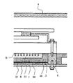
- FIG. 1 is a schematic cross-sectional view of the electrical component housing 100 according to the first embodiment, and is a cross-sectional view of the electrical component housing 100 viewed from the side.
- the electrical component housing 100 is a housing that accommodates electrical components such as the inverter 1 and the smoothing capacitor 2 .
- the electrical component housing 100 includes a resin base portion 3 on which the inverter 1 and the smoothing capacitor 2 are placed, a metal cover portion 4 attached to the base portion 3 so as to cover the inverter 1 and the smoothing capacitor 2, and a metal plate 5 abutting on the bottom surface 34 of the base portion 3 so as to cover the bottom surface 34 of the base portion 3 .
- the base portion 3 is formed with a coolant flow path 31 passing below the position where the inverter 1 is placed, and a through hole 32 in which the conductive member 6 is provided.
- the inverter 1 housed in the electrical component housing 100 includes a power module 11 containing a semiconductor element, a control board 12 having a control circuit, and the like, and has a function of converting electric power into direct current or alternating current.
- the inverter 1 is fixed to the base portion 3 of the electrical component housing 100 with bolts or the like.
- the inverter 1 also includes a ground terminal 13 , which is electrically connected to the conductive member 6 via a busbar (conductor) 14 .
- the smoothing capacitor 2 housed in the electrical component housing 100 is configured by housing a capacitor element in a capacitor case, and is fixed to the base portion 3 with bolts (not shown).
- the base portion 3 is made of an electrically insulating resin material such as polyphenylene sulfide (PPS) or polyphthalamide (PPA) as a plate member, and the inverter 1 and the smoothing capacitor 2 are mounted on the mounting surface 33 .
- PPS polyphenylene sulfide
- PPA polyphthalamide
- a metal plate 5 made of iron, aluminum, or the like, which is larger than the outer shape of the bottom surface 34 is in contact with the bottom surface 34 of the base portion 3 . That is, the bottom surface 34 of the base portion 3 is covered with the metal plate 5 .
- the base portion 3 includes a first member (base main body) 36 having an opening 35 for forming the coolant channel 31 and a second member (resin plate) 37 .
- the opening 35 of the first member 36 opens downward, and the second member 37 is welded (bonded) to the first member 36 so as to cover the opening 35 .
- the space formed by sealing the opening 35 with the second member 37 serves as the coolant channel 31 .
- a joint portion 38 between the first member 36 and the second member 37 is formed along the coolant channel 31 around the coolant channel 31 .
- the upper part of the first member 36 is also opened, and the upper opening part is covered with the inverter 1, but this is not necessarily the case, and the upper part of the first member 36 may be closed. .
- the coolant channel 31 passes below the position where the inverter 1 is placed in the base portion 3 , and cooling water for cooling the inverter 1 flows through the coolant channel 31 .
- a fin 15 is provided in the lower portion of the inverter 1 , and the fin 15 is in contact with cooling water flowing through the refrigerant flow path 31 .
- the inverter 1 is efficiently cooled.
- the inverter 1 may be fixed to the base portion 3 via a substrate or the like having a plurality of holes through which the fins 15 pass.
- the inverter 1 is provided with the fins 15 to be brought into contact with the cooling water, it is not necessarily limited to this, and the fins 15 may not be provided.
- the base portion 3 has a through hole 32 penetrating through the base portion 3 in the thickness direction of the base portion 3 , and a conductive member 6 electrically connected to the ground terminal 13 of the inverter 1 is provided in the through hole 32 . is provided. The details of the installation of the conductive member 6 will be described later.
- the cover part 4 is made of a metal material such as aluminum, and is attached to the base part 3 so as to cover the inverter 1 and the smoothing capacitor 2 .
- the cover portion 4 has a stepped portion 41 having an end surface that abuts on the mounting surface 33 of the base portion 3 at the inner portion of the side wall. abuts on the outer periphery of the The cover portion 4, the base portion 3, and the metal plate 5 are fastened together from the outside of the metal plate 5 with bolts or the like at the portion where the stepped portion 41 of the cover portion 4 and the mounting surface 33 of the base portion 3 abut. be concluded.
- the electrical component housing 100 configured as described above, by making the base portion 3 of resin, weight reduction, cost reduction, and improvement in workability are realized, and the metal cover portion 4 and the metal By covering the periphery with the plate 5, the electromagnetic shielding property is enhanced.
- the ground terminal of the electric parts inside the case must be grounded (electrically connected) to the metal part of the housing.
- the base portion on which electrical components are mounted is made of a resin material
- the electrical component housing 100 it is difficult to assemble the electrical component housing 100 in a state where the ground terminal 13 of the inverter 1 and the metal cover portion 4 are connected by a ground wire or the like. Also, in order to enable assembly work, the length of the ground wire harness must be lengthened. is likely to decrease.
- a through-hole 32 is provided in the base portion 3 of the electric component housing 100 so as to pass through the base portion 3 in the thickness direction.
- a conductive member 6 for electrically connecting the plate 5 is provided.
- the base portion 3 of the electrical component housing 100 is formed with a through hole 32 passing through the base portion 3 in the thickness direction of the base portion 3.
- the through hole 32 contains aluminum or the like.
- a conductive member 6 made of metal is provided.
- a seal member (not shown) seals between the conductive member 6 and the inner peripheral surface of the through hole 32 .
- a bus bar 14 connected to the ground terminal 13 of the inverter 1 is fixed to the upper surface 61 of the conductive member 6 with a bolt or the like.
- the bottom surface 62 of the conductive member 6 is in contact with the top surface of the metal plate 5 covering the bottom surface 34 of the base portion 3, and the metal plate 5 is attached to the bottom surface 62 of the conductive member 6 by bolts or the like from the metal plate 5 side. Fixed. Thereby, the ground terminal 13 of the inverter 1 and the metal plate 5 are electrically connected via the conductive member 6 .
- the through hole 32 is preferably formed at a position as close to the inverter 1 as possible. Thereby, the distance between the ground terminal 13 of the inverter 1 and the conductive member 6 can be shortened, and the length of the bus bar 14 can be shortened.
- the bus bar 14 that connects to the ground terminal 13 of the inverter 1 is connected (fixed) to the conductive member 6 with a bolt or the like.
- the cover portion 4 , the base portion 3 and the metal plate 5 are fastened together, and the metal plate 5 is electrically connected to the metal plate 5 with bolts or the like from the side of the metal plate 5 so that the metal plate 5 contacts the bottom surface 62 of the conductive member 6 . 6, is fastened. Since the inverter 1 is connected to the ground by fastening the metal plate 5 to the conductive member 6 in this way, the electrical component housing 100 is assembled with the ground wire connected to the inner wall of the cover portion 4 and the metal plate 5 . No need. Therefore, the ease of assembly of the electrical component housing 100 is improved.
- the electric component casing 100 is attached to a resin base portion 3 on which the inverter 1 and the smoothing capacitor 2 (electrical components) are placed, and to the base portion 3 so as to cover the inverter 1 and the smoothing capacitor 2 (electrical components). and a cover portion 4 made of metal.
- the electrical component housing 100 includes a metal plate 5 that abuts on the bottom surface 34 of the base portion 3 so as to cover the bottom surface 34 of the base portion 3, and a through hole that penetrates the base portion 3 in the thickness direction of the base portion 3. and a conductive member 6 provided within 32 . Conductive member 6 electrically connects ground terminal 13 of inverter 1 (electric component) and metal plate 5 .
- the conductive member 6 electrically connected to the ground terminal 13 is provided on the base portion 3 in this manner, the metal plate 5 and the conductive member 6 are brought into contact with each other when the electrical component housing 100 is assembled.
- the ground terminal 13 of the inverter 1 (electrical component) is connected to the ground only by this connection. That is, it is not necessary to assemble the electrical component housing 100 in a state where the ground wire or the like is connected to the inner wall of the cover portion 4 (metal portion) of the electrical component housing 100, thereby improving assembling workability.
- the ground terminal 13 of the inverter 1 (electric component) is connected to the ground simply by bringing the metal plate 5 and the conductive member 6 into contact with each other. There is no need to lengthen the harness length of the wire. Therefore, deterioration of EMC performance can be suppressed.
- the electrical component housing 100 includes a coolant channel 31 through which cooling water (refrigerant) for cooling the inverter 1 (electrical component) flows through the base portion 3 , and the inverter 1 (electrical component) is placed in the coolant channel 31 . pass under the position As a result, the inverter 1 (electric component) is efficiently cooled.
- cooling water refrigerant
- the coolant channel 31 is not an essential component. That is, even if the refrigerant flow path 31 is not provided, it is possible to obtain the effect of improving the assembling workability.
- the coolant flow path 31 is configured to pass below the position where the inverter 1 is mounted, but the coolant flow path 31 may also pass below the position where the smoothing capacitor 2 is mounted. may be formed in
- the second member 37 is welded to the first member 36 so as to cover the opening 35 to form the coolant channel 31.
- the method is not limited to welding, and any known method may be used.
- a gasket seal may be used to join.
- FIG. 2 is a schematic cross-sectional view of the electrical component housing 100 according to the second embodiment. As shown in FIG. 2, in this embodiment, the shape of the coolant channel 31 is different from that in the first embodiment.
- the coolant channel 31 is also formed in the base portion 3 in this embodiment.
- a protruding portion 39 protruding toward the center in the width direction of 31 is formed. That is, the first member (base main body) 36 of the base portion 3 has a portion extending below the position where the inverter 1 is placed so that the projecting portion 39 is formed.
- a joint portion 38 to which the first member 36 and the second member (resin plate) 37 are welded (joined) is formed on the lower surface of the projecting portion 39 .
- the conductive member 6 provided in the through hole 32 of the base portion 3 is placed in the vicinity of the projecting portion 39 and directly below the inverter 1, and the upper surface 61 is the bottom surface of the inverter 1. is in contact with A bus bar 14 connected to a ground terminal 13 of the inverter 1 is in contact with the inverter 1 above the position where the conductive member 6 and the inverter 1 are in contact with each other.
- the elastic member 6 is fastened together with a bolt or the like from the bus bar 14 side.
- the bottom surface 62 of the conductive member 6 is fastened to the metal plate 5 covering the bottom surface 34 of the base portion 3 with bolts or the like. Thereby, the ground terminal 13 and the metal plate 5 are electrically connected via the conductive member 6 .
- the conductive member 6 (through hole 32) is provided at a position where the joint portion 38 is present, the sealing performance of the coolant flow path 31 is deteriorated. There is a need to. Therefore, if the coolant channel 31 does not have the projecting portion 39 , the conductive member 6 must be provided at a position away from the coolant channel 31 avoiding the joint portion 38 around the coolant channel 31 .
- the refrigerant flow path 31 below the inverter 1 is provided with a projecting portion 39 projecting from the inner peripheral surface of the opening 35 toward the center of the refrigerant flow path 31 in the width direction.
- a joint portion 38 is formed on the lower surface of 39 .
- the joint portion 38 is formed on the lower surface of the projecting portion 39 in this way, the conductive member 6 can be installed near the projecting portion 39 , that is, near the refrigerant flow path 31 below the inverter 1 . Therefore, the distance between the inverter 1 and the conductive member 6 can be shortened. As a result, the busbar 14 connecting the ground terminal 13 of the inverter 1 and the conductive member 6 can be shortened, so that the inductance of the busbar 14 is reduced and the EMC performance is improved.
- the conductive member 6 can be installed near the coolant channel 31 below the inverter 1, the conductive member 6 can be installed directly below the inverter 1 as shown in FIG. .
- the conductive member 6 is installed directly under the inverter 1, and the ground terminal 13 (the bus bar 14 connected to it), the power module 11 of the inverter 1, and the conductive member 6 are , bolts, etc., and are fastened together. That is, a fixing member (bolt or the like) for fixing the inverter 1 to the base portion 3 and a fixing member (bolt or the like) for fixing the bus bar 14 (conductor) connected to the ground terminal 13 to the conductive member 6 are separated. do not have. Therefore, the number of parts can be reduced, and the ground connection of the inverter 1 (electric parts) can be realized compactly and inexpensively.
- a projecting portion 39 is formed in the coolant flow path 31 below the inverter 1 (the electrical component) and projects from the inner peripheral surface of the opening 35 toward the center of the coolant flow path 31 in the width direction.
- a joint portion 38 is formed on the lower surface of the projecting portion 39 .
- the conductive member 6 is provided in the vicinity of the projecting portion 39 .
- the joint portion 38 is formed on the lower surface of the projecting portion 39 , and the conductive member 6 is installed near the projecting portion 39 , that is, near the refrigerant flow path 31 below the inverter 1 .
- the busbar (conductor) 14 connecting the inverter 1 and the conductive member 6 can be shortened, the inductance of the busbar (conductor) 14 is reduced, and the EMC performance is improved.
- the conductive member 6 is integrated with the inverter 1 (electrical component) directly below the inverter 1 (electrical component) and the bus bar 14 (conductor) connected to the ground terminal 13 of the inverter 1 (electrical component). and signed. That is, a fixing member (bolt or the like) for fixing the inverter 1 (electrical component) to the base portion 3, and a fixing member (bolt or the like) for fixing the bus bar 14 (conductor) connected to the ground terminal 13 to the conductive member 6. are not separated. Therefore, the number of parts can be reduced, and the ground connection of the inverter 1 (electric parts) can be realized compactly and inexpensively.
- the installation position of the conductive member 6 is not necessarily limited to this, and any position near the projecting portion 39 can be used. may be set to If the conductive member 6 is installed in the vicinity of the projecting portion 39, the distance between the inverter 1 and the conductive member 6 can be shortened, and the ECM performance is improved.
- FIG. 3 is a schematic cross-sectional view of the electrical component housing 100 according to the third embodiment. As shown in FIG. 3, in this embodiment, the shape of the conductive member 6 is different from that of the other embodiments.
- a coolant channel 31 is also formed in the base portion 3 in this embodiment.
- a joint portion 38 between the first member 36 and the second member 37 is formed along the coolant channel 31 around the coolant channel 31 .
- the conductive member 6 is bent in a crank shape so as to avoid the joint portion 38 .
- the conductive member 6 can be installed in the vicinity of the refrigerant flow path 31 under the inverter 1, and the distance between the inverter 1 and the conductive member 6 can be shortened. Therefore, the bus bar 14 connecting the inverter 1 and the conductive member 6 can be shortened, the inductance of the bus bar 14 is reduced, and the EMC performance is improved.
- the conductive member 6 is provided below the inverter 1 and near the coolant channel 31 .
- a top surface 61 of the conductive member 6 is positioned directly below the inverter 1 and is in contact with the bottom surface of the inverter 1 .
- a bus bar 14 connected to a ground terminal 13 of the inverter 1 is in contact with the inverter 1 above the position where the conductive member 6 and the inverter 1 are in contact with each other.
- the elastic member 6 is fastened together with a bolt 63 or the like from the bus bar 14 side.
- the through-hole 32 of the base portion 3 and the conductive member 6 in the through-hole 32 are bent in a direction away from the coolant channel 31 at the upper portion, and bent downward at a position outside the position where the joint portion 38 is located. ing. That is, the conductive member 6 is bent like a crank in the vicinity of the refrigerant flow path 31 below the inverter 1 so as to avoid the joint portion 38 .
- the bottom surface 62 of the conductive member 6 abuts the top surface of the metal plate 5 and is fixed to the metal plate 5 with bolts 64 or the like.
- the bolts 63 and 64 overlap each other in the height (vertical) direction of the electrical component housing 100 .
- the conductive member 6 is provided in the vicinity of the refrigerant flow path 31 below the inverter 1 in such a shape as to avoid the joint portion 38, the distance between the inverter 1 and the conductive member 6 can be shortened. Further, since the conductive member 6 is bent in a crank shape, the bolt 63 for fixing the bus bar 14 and the upper surface 61 of the conductive member 6 and the bottom surface 62 of the conductive member 6 and the metal plate 5 are fixed. The bolts 64 can be provided so as to overlap each other in the height (vertical) direction of the electrical component housing 100 . As a result, the heights of the conductive member 6 and the base portion 3 can be reduced, resulting in further space saving and cost reduction.
- the conductive member 6 is installed directly under the inverter 1, and the ground terminal 13 (the bus bar 14 connected to it), the inverter 1, and the conductive member 6 are integrated and fastened.
- a fixing member (bolt or the like) for fixing the inverter 1 (electric component) to the base portion 3 and a fixing member (bolt or the like) for fixing the bus bar 14 (conductor) connected to the ground terminal 13 to the conductive member 6 are provided. , reducing the number of parts. Therefore, the ground connection of the inverter 1 (electric component) can be realized more compactly and inexpensively.
- the conductive member 6 is bent in a crank shape so as to avoid the joint portion 38 in the vicinity of the coolant flow path 31 below the inverter 1 (electrical component). Since the conductive member 6 is provided in the vicinity of the refrigerant flow path 31 below the inverter 1 in such a shape as to avoid the joint portion 38, the distance between the inverter 1 (electric component) and the conductive member 6 is shortened. be able to. Therefore, the bus bar 14 (conductor) connecting the inverter 1 (electric component) and the conductive member 6 can be shortened, the inductance is reduced, and the EMC performance is improved.
- the bolt 63 (fixing member) for fixing the bus bar 14 and the upper surface 61 of the conductive member 6, the bottom surface 62 of the conductive member 6 and the metal plate A bolt 64 (fixing member) for fixing 5 can be provided so as to overlap in the height (vertical) direction of the electrical component housing 100 .
- the heights of the conductive member 6 and the base portion 3 can be reduced, resulting in further space saving and cost reduction.
- the conductive member 6 is integrated with the inverter 1 (electrical component) directly below the inverter 1 (electrical component) and the bus bar 14 (conductor) connected to the ground terminal 13 of the inverter 1 (electrical component). and signed. That is, a fixing member (bolt or the like) for fixing the inverter 1 (electrical component) to the base portion 3, and a fixing member (bolt or the like) for fixing the bus bar 14 (conductor) connected to the ground terminal 13 to the conductive member 6. are not separated. Therefore, the number of parts is reduced, and the ground connection of the inverter 1 (electric parts) can be realized more compactly and inexpensively.
- the installation position of the conductive member 6 is not necessarily limited to this. It may be provided at any position. If the conductive member 6 is installed in the vicinity of the refrigerant flow path 31 below the inverter 1, the distance between the inverter 1 and the conductive member 6 can be shortened, improving the ECM performance.
- FIG. 4 An electrical component housing 100 according to a fourth embodiment will be described with reference to FIGS. 4 and 5.
- FIG. Elements similar to those of other embodiments are denoted by the same reference numerals, and descriptions thereof are omitted.
- FIG. 4A and 4B are bottom views of the electrical component housing 100 according to the fourth embodiment
- FIG. 5A is a cross-sectional view along line A-A in FIG. 4
- FIG. 5B is a cross-sectional view along line B-B in FIG. 1 is a cross-sectional view along FIG.
- This embodiment differs from the other embodiments in that a reinforcing member 7 is provided in the coolant channel 31 .
- the coolant channel 31 has a channel inlet 311 through which cooling water flows into the electrical component housing 100 , and the cooling water that cools the inverter 1 flows out of the electrical component housing 100 . It has a channel outlet 312 .
- the coolant channel 31 has a rectangular portion 313 formed between the channel inlet 311 and the channel outlet 312 and having a channel width wider than that of other portions and having a substantially rectangular shape when viewed from the top (bottom). have.
- the inverter 1 is mounted on the base portion 3 above the rectangular portion 313 .
- a joint portion 38 is formed along the coolant channel 31 around the coolant channel 31 .
- the corner portion closest to the center of the electrical component housing 100 among the squares is recessed toward the inside of the coolant channel 31 .
- a conductive member 6 is installed in this intruded portion. Accordingly, the conductive member 6 can be arranged directly below the inverter 1 above the rectangular portion 313, and the distance between the conductive member 6 and the inverter 1 can be shortened. Therefore, the distance of the busbar 14 connecting the inverter 1 and the conductive member 6 can be shortened, the inductance of the busbar 14 is reduced, and the EMC performance is improved. In addition, since the conductive member 6 is arranged inside the inverter 1 (immediately below the inverter 1) when viewed from above, the space is further reduced.
- a reinforcing material 7 for securing the rigidity of the base portion 3 is provided on a diagonal line connecting a corner portion closest to the center of the electrical component housing 100 and a corner portion opposite thereto. It is provided across the flow path 31 .
- a reinforcing material 7 for securing the rigidity of the base portion 3 is provided on a diagonal line connecting a corner portion closest to the center of the electrical component housing 100 and a corner portion opposite thereto. It is provided across the flow path 31 .
- An outlet 315 is formed.
- the rectangular portion inlet 314 and the rectangular portion outlet 315 are formed so that the passage width of the refrigerant passage 31 is narrower than that inside the rectangular portion 313 .
- the reinforcing member 7 in the rectangular portion 313 constitutes a part of the first member (base main body) 36 and extends upward from the bottom surface of the coolant channel 31 (that is, the top surface of the second member (resin plate)). is set.
- the bottom surface of the reinforcing member 7 abuts on the top surface of the second member (resin plate) 37, and the reinforcing member 7 and the second member 37 are bonded at a joining portion 38 where the bottom surface of the reinforcing member 7 and the second member 37 abut. are joined by welding or the like.
- the reinforcing member 7 is configured to be lower than the coolant flow path 31 .
- the cooling water in the coolant channel 31 flows through the tip 71 of the reinforcing member 7 . That is, as indicated by the arrows in FIG. 5A, the cooling water in the coolant channel 31 first flows from the rectangular portion inlet 314 toward the tip 71 of the reinforcing member 7 (above the coolant channel 31), from the tip 71 toward the rectangular section outlet 315 .
- the cooling water in the refrigerant flow path 31 (rectangular portion 313 ) is prevented from being biased downward, and the cooling water flows evenly along the fins 15 of the inverter 1 . Therefore, the cooling efficiency of the inverter 1 is increased.
- the rectangular portion inlet 314 and the rectangular portion outlet 315 are formed to have a narrower passage width of the coolant passage 31 than the rectangular portion 313, the flow velocity of the cooling water in the rectangular portion 313 increases. The cooling efficiency of inverter 1 is further increased.
- the reinforcing member 7 is configured as a part of the first member (base body) 36, but this is not necessarily the case. may be provided.
- the electric component housing 100 includes fins 15 that allow the inverter 1 (electrical component) to come into contact with the cooling water in the coolant flow path 31 .
- a reinforcing member 7 that crosses the refrigerant flow path 31 is erected from a second member (resin plate) 37 in the refrigerant flow path 31 below the inverter 1 (electrical component). is lower than the coolant flow path 31 so that the cooling water passes through the tip 71 of the .
- the cooling water in the refrigerant flow path 31 is prevented from being biased downward, and the cooling water flows evenly along the fins 15 of the inverter 1 . Therefore, the cooling efficiency of the inverter 1 is increased.
- the refrigerant channel 31 it is preferable to provide the refrigerant channel 31 with the rectangular portion 313 having a wider channel width than other portions to increase the flow velocity in the rectangular portion 313, but the rectangular portion 313 is not necessarily provided. It doesn't have to be. If the reinforcing member 7 crossing the refrigerant flow path 31 is provided in the refrigerant flow path 31 below the inverter 1, the unevenness of the cooling water is suppressed and the cooling efficiency of the inverter 1 is increased.
- FIG. 6 to 9 An electrical component housing 100 according to a fifth embodiment will be described with reference to FIGS. 6 to 9.
- FIG. Elements similar to those of other embodiments are denoted by the same reference numerals, and descriptions thereof are omitted.
- FIG. 6 is a schematic cross-sectional view of the electrical component housing 100 according to the fifth embodiment
- FIG. 7 is a bottom view of the electrical component housing 100.
- the conductive member 6 is provided near the central portion of the electrical component housing 100 .
- the ground terminal 13 of the inverter 1 and the metal plate 5 are connected through the conductive member 6 in the through hole 32 of the base portion 3 as in the other embodiments. electrically connected.
- the bottom surface 62 of the conductive member 6 contacts the top surface of the metal plate 5, and the metal plate 5 is fixed to the bottom surface 62 of the conductive member 6 with bolts 64 or the like.
- the conductive member 6 is provided near the central portion of the electrical component housing 100, and as shown in FIG. are fastened from the metal plate 5 side by bolts 64 or the like.
- the peripheral portion of the metal plate 5 is fastened together with the base portion 3 and the cover portion 4 with bolts or the like (FIGS. 6 and 7).
- the metal plate covering the bottom surface of the base generally has low rigidity. It vibrates.
- the metal plate 5' is fixed to the base portion 3' and the cover portion 4' only at the peripheral edge portion of the metal plate 5'. membrane vibrates in the center of the As a result, resonance occurs at low frequencies, degrading the sound and vibration performance of the electrical component housing 100'.
- the metal plate 5 covering the bottom surface 34 of the base portion 3 is fixed to the base portion 3 and the cover portion 4 by bolts or the like at the peripheral portion, and the central portion of the electrical component housing 100 is fixed. It is fixed to the conductive member 6 by bolts 64 or the like in the vicinity. Thereby, as shown in FIG. 9, resonance is suppressed even if the metal plate 5 vibrates, and deterioration of sound vibration performance is suppressed.
- the conductive member 6 Even if the conductive member 6 is provided at a position other than the central portion of the electrical component housing 100, if the metal plate 5 is fixed to the conductive member 6 with bolts or the like, the noise and vibration performance deteriorates. can be suppressed to some extent. However, by arranging the conductive member 6 in the vicinity of the central portion of the electrical component housing 100 and fixing the metal plate 5 to the conductive member 6, it is possible to more effectively suppress the deterioration of the sound and vibration performance. .
- the conductive member 6 is provided near the central portion of the electrical component housing 100 , and the metal plate 5 covering the bottom surface 34 of the base portion 3 is fixed to the conductive member 6 .
- the metal plate 5 is fixed to the conductive member 6 in the vicinity of the central portion of the electrical component housing 100, so that even if the metal plate 5 vibrates, resonance is suppressed and deterioration of sound vibration performance is suppressed. be.
- the inverter 1 and the smoothing capacitor 2 are housed in the electrical component housing 100, but the electrical components housed in the electrical component housing 100 are not limited to these. Moreover, the number of electrical components accommodated in the electrical component housing 100 is also arbitrary, and may be, for example, one electrical component, or may accommodate a plurality of electrical components.
- the ground terminal 13 of the inverter 1 and the conductive member 6 are electrically connected by the bus bar 14, but this is not necessarily the case.
- a wire harness or the like may be used as a conductor that connects the ground terminal 13 and the conductive member 6 .
- cooling water is used as the coolant flowing through the coolant channel 31, but the coolant is not limited to this, and may be, for example, coolant gas.
Abstract
Description
図1を参照して、本発明の第1実施形態に係る電気部品用筐体100について説明する。 (First embodiment)
An electrical component housing 100 according to a first embodiment of the present invention will be described with reference to FIG.
図2を参照して、第2実施形態による電気部品用筐体100を説明する。なお、第1実施形態と同様の要素には同一の符号を付し、その説明を省略する。 (Second embodiment)
An
図3を参照して、第3実施形態による電気部品用筐体100を説明する。なお、他の実施形態と同様の要素には同一の符号を付し、その説明を省略する。 (Third Embodiment)
An
図4及び図5を参照して、第4実施形態による電気部品用筐体100を説明する。なお、他の実施形態と同様の要素には同一の符号を付し、その説明を省略する。 (Fourth embodiment)
An
図6~図9を参照して、第5実施形態による電気部品用筐体100を説明する。なお、他の実施形態と同様の要素には同一の符号を付し、その説明を省略する。 (Fifth embodiment)
An
Claims (8)
- 電気部品を収容する電気部品用筐体であって、
前記電気部品を載置する樹脂製のベース部と、
前記電気部品を覆うように前記ベース部に取り付けられる金属製のカバー部と、
前記ベース部の底面を覆うように前記ベース部の底面に当接する金属板と、
前記ベース部の厚さ方向に前記ベース部を貫通する貫通孔内に設けられる導電性部材と、を備え、
前記導電性部材は、前記電気部品のグランド端子と前記金属板とを電気的に接続する、
電気部品用筐体。 An electrical component housing for housing an electrical component,
a resin base on which the electrical component is placed;
a metal cover portion attached to the base portion so as to cover the electrical component;
a metal plate in contact with the bottom surface of the base portion so as to cover the bottom surface of the base portion;
a conductive member provided in a through hole that penetrates the base portion in the thickness direction of the base portion;
The conductive member electrically connects the ground terminal of the electrical component and the metal plate,
Enclosure for electrical components. - 請求項1に記載の電気部品用筐体であって、
前記ベース部は、前記電気部品を冷却する冷媒が流れる冷媒流路を備え、
前記冷媒流路は、前記電気部品が載置された位置の下方を通る、
電気部品用筐体。 The housing for electrical components according to claim 1,
the base portion includes a coolant channel through which a coolant for cooling the electrical component flows;
wherein the coolant channel passes below a position where the electrical component is placed;
Enclosure for electrical components. - 請求項2に記載の電気部品用筐体であって、
前記ベース部は、下方に向かって開口する開口部を有するベース本体と、当該開口部を覆うように前記ベース本体に接合される樹脂板とから構成され、
前記冷媒流路は、前記樹脂板により前記開口部を封止することで形成され、
前記ベース本体と前記樹脂板との接合部位が前記冷媒流路に沿って形成される、
電気部品用筐体。 The housing for electrical components according to claim 2,
The base portion is composed of a base body having an opening that opens downward, and a resin plate that is joined to the base body so as to cover the opening,
The coolant channel is formed by sealing the opening with the resin plate,
a joint portion between the base body and the resin plate is formed along the coolant channel;
Enclosure for electrical components. - 請求項3に記載の電気部品用筐体であって、
前記電気部品の下方における前記冷媒流路には、前記開口部の内周面から前記冷媒流路の幅方向中央に向かって突出する突出部が形成されており、
前記突出部の下面には前記接合部位が形成され、
前記導電性部材は、前記突出部の近傍に設けられる、
電気部品用筐体。 The housing for electrical components according to claim 3,
A protrusion projecting from an inner peripheral surface of the opening toward the center of the coolant channel in the width direction is formed in the coolant channel below the electrical component,
The joint portion is formed on the lower surface of the protrusion,
The conductive member is provided in the vicinity of the protrusion,
Enclosure for electrical components. - 請求項3に記載の電気部品用筐体であって、
前記導電性部材は、前記電気部品の下方における前記冷媒流路の近傍において、前記接合部位を避けるようにクランク状に屈曲して設けられる、
電気部品用筐体。 The housing for electrical components according to claim 3,
The conductive member is bent in a crank shape so as to avoid the joint portion in the vicinity of the coolant flow path below the electrical component.
Enclosure for electrical components. - 請求項4または5に記載の電気部品用筐体であって、
前記導電性部材は、前記電気部品の直下において、前記電気部品及び前記電気部品の前記グランド端子に接続する導体と一体化して締結される、
電気部品用筐体。 The electrical component housing according to claim 4 or 5,
The conductive member is integrally fastened directly under the electrical component with the electrical component and the conductor connected to the ground terminal of the electrical component,
Enclosure for electrical components. - 請求項3から6のいずれか一つに記載の電気部品用筐体であって、
前記電気部品は、前記冷媒流路内の冷媒に接触するフィンを備え、
前記電気部品の下方の前記冷媒流路内には、前記冷媒流路を横断する補強材が前記冷媒流路の底面から上方に向かって立設され、
前記補強材は、前記補強材の先端を前記冷媒が通過するように前記冷媒流路よりも低く構成される、
電気部品用筐体。 The electrical component housing according to any one of claims 3 to 6,
the electrical component includes fins that contact the coolant in the coolant channel;
A reinforcing member that crosses the coolant flow path is erected upward from the bottom surface of the coolant flow path in the coolant flow path below the electrical component,
The reinforcing member is configured to be lower than the coolant channel so that the coolant passes through the tip of the reinforcing member.
Enclosure for electrical components. - 請求項1から7のいずれか一つに記載の電気部品用筐体であって、
前記導電性部材は、前記電気部品用筐体の中央部付近に設けられ、
前記金属板は、前記導電性部材に固定される、
電気部品用筐体。 The electrical component housing according to any one of claims 1 to 7,
The conductive member is provided near a central portion of the electrical component housing,
wherein the metal plate is fixed to the conductive member;
Enclosure for electrical components.
Priority Applications (4)
| Application Number | Priority Date | Filing Date | Title |
|---|---|---|---|
| JP2023527128A JPWO2022259006A1 (en) | 2021-06-08 | 2021-06-08 | |
| CN202180099036.8A CN117426146A (en) | 2021-06-08 | 2021-06-08 | Housing for electrical component |
| EP21944439.5A EP4355041A1 (en) | 2021-06-08 | 2021-06-08 | Electrical component housing |
| PCT/IB2021/000400 WO2022259006A1 (en) | 2021-06-08 | 2021-06-08 | Electrical component housing |
Applications Claiming Priority (1)
| Application Number | Priority Date | Filing Date | Title |
|---|---|---|---|
| PCT/IB2021/000400 WO2022259006A1 (en) | 2021-06-08 | 2021-06-08 | Electrical component housing |
Publications (1)
| Publication Number | Publication Date |
|---|---|
| WO2022259006A1 true WO2022259006A1 (en) | 2022-12-15 |
Family
ID=84424793
Family Applications (1)
| Application Number | Title | Priority Date | Filing Date |
|---|---|---|---|
| PCT/IB2021/000400 WO2022259006A1 (en) | 2021-06-08 | 2021-06-08 | Electrical component housing |
Country Status (4)
| Country | Link |
|---|---|
| EP (1) | EP4355041A1 (en) |
| JP (1) | JPWO2022259006A1 (en) |
| CN (1) | CN117426146A (en) |
| WO (1) | WO2022259006A1 (en) |
Citations (7)
| Publication number | Priority date | Publication date | Assignee | Title |
|---|---|---|---|---|
| JPH10178151A (en) * | 1996-11-06 | 1998-06-30 | Temic Telefunken Microelectron Gmbh | Power module for controlling electric motor |
| JP2011233726A (en) * | 2010-04-28 | 2011-11-17 | Kojima Press Industry Co Ltd | Cooling case for electronic parts |
| WO2012124074A1 (en) * | 2011-03-16 | 2012-09-20 | トヨタ自動車株式会社 | Substrate unit |
| CN104298327A (en) * | 2014-09-24 | 2015-01-21 | 齐齐哈尔大学 | Computer water-cooling heat exchange device and computer adopting same |
| JP2016059242A (en) * | 2014-09-12 | 2016-04-21 | 株式会社豊田自動織機 | Power conversion device |
| WO2019175928A1 (en) | 2018-03-12 | 2019-09-19 | 日産自動車株式会社 | Housing for electronic component |
| CN211831654U (en) * | 2020-04-28 | 2020-10-30 | 华中科技大学 | Efficient liquid cooling plate and equipment |
-
2021
- 2021-06-08 JP JP2023527128A patent/JPWO2022259006A1/ja active Pending
- 2021-06-08 EP EP21944439.5A patent/EP4355041A1/en active Pending
- 2021-06-08 CN CN202180099036.8A patent/CN117426146A/en active Pending
- 2021-06-08 WO PCT/IB2021/000400 patent/WO2022259006A1/en active Application Filing
Patent Citations (7)
| Publication number | Priority date | Publication date | Assignee | Title |
|---|---|---|---|---|
| JPH10178151A (en) * | 1996-11-06 | 1998-06-30 | Temic Telefunken Microelectron Gmbh | Power module for controlling electric motor |
| JP2011233726A (en) * | 2010-04-28 | 2011-11-17 | Kojima Press Industry Co Ltd | Cooling case for electronic parts |
| WO2012124074A1 (en) * | 2011-03-16 | 2012-09-20 | トヨタ自動車株式会社 | Substrate unit |
| JP2016059242A (en) * | 2014-09-12 | 2016-04-21 | 株式会社豊田自動織機 | Power conversion device |
| CN104298327A (en) * | 2014-09-24 | 2015-01-21 | 齐齐哈尔大学 | Computer water-cooling heat exchange device and computer adopting same |
| WO2019175928A1 (en) | 2018-03-12 | 2019-09-19 | 日産自動車株式会社 | Housing for electronic component |
| CN211831654U (en) * | 2020-04-28 | 2020-10-30 | 华中科技大学 | Efficient liquid cooling plate and equipment |
Also Published As
| Publication number | Publication date |
|---|---|
| EP4355041A1 (en) | 2024-04-17 |
| CN117426146A (en) | 2024-01-19 |
| JPWO2022259006A1 (en) | 2022-12-15 |
Similar Documents
| Publication | Publication Date | Title |
|---|---|---|
| JP4764365B2 (en) | Inverter-integrated electric compressor | |
| US8582291B2 (en) | Power conversion apparatus | |
| US8929097B2 (en) | Power conversion apparatus | |
| US8724313B2 (en) | Power conversion apparatus | |
| US8514590B2 (en) | Power conversion apparatus | |
| US10132535B2 (en) | Inverter-integrated electric compressor | |
| US9345160B2 (en) | Electronic device | |
| JP5107114B2 (en) | Inverter-integrated electric compressor | |
| JP5582749B2 (en) | Inverter-integrated electric compressor | |
| US8435019B2 (en) | Vehicle-air-conditioner electric compressor | |
| US20160020657A1 (en) | Inverter-integrated electric compressor | |
| US10205429B2 (en) | Output-noise reduction device | |
| JP6298974B2 (en) | Output noise reduction device | |
| JP7140262B2 (en) | power converter | |
| EP3151401B1 (en) | Noise reduction device | |
| CN107148731B (en) | Power conversion device | |
| JP2012105418A (en) | Electric power conversion apparatus | |
| WO2022259006A1 (en) | Electrical component housing | |
| JP7282265B2 (en) | power converter | |
| JP6760691B1 (en) | Power converter | |
| JP7046146B1 (en) | Power converter | |
| EP4350969A1 (en) | Bus bar heat dissipation structure and inverter device | |
| WO2020201799A1 (en) | Power conversion device | |
| JP6483331B1 (en) | Power converter | |
| JP5609811B2 (en) | Power supply |
Legal Events
| Date | Code | Title | Description |
|---|---|---|---|
| 121 | Ep: the epo has been informed by wipo that ep was designated in this application |
Ref document number: 21944439 Country of ref document: EP Kind code of ref document: A1 |
|
| WWE | Wipo information: entry into national phase |
Ref document number: 2023527128 Country of ref document: JP |
|
| WWE | Wipo information: entry into national phase |
Ref document number: 2021944439 Country of ref document: EP |
|
| NENP | Non-entry into the national phase |
Ref country code: DE |
|
| ENP | Entry into the national phase |
Ref document number: 2021944439 Country of ref document: EP Effective date: 20240108 |