WO2022255386A1 - Procédé de détermination de mesure d'incitation, serveur et programme - Google Patents
Procédé de détermination de mesure d'incitation, serveur et programme Download PDFInfo
- Publication number
- WO2022255386A1 WO2022255386A1 PCT/JP2022/022218 JP2022022218W WO2022255386A1 WO 2022255386 A1 WO2022255386 A1 WO 2022255386A1 JP 2022022218 W JP2022022218 W JP 2022022218W WO 2022255386 A1 WO2022255386 A1 WO 2022255386A1
- Authority
- WO
- WIPO (PCT)
- Prior art keywords
- data
- identification information
- information
- value
- usage
- Prior art date
Links
- 238000000034 method Methods 0.000 title claims abstract description 42
- 230000008859 change Effects 0.000 claims description 41
- 238000012508 change request Methods 0.000 claims description 32
- 238000007726 management method Methods 0.000 description 258
- 238000004891 communication Methods 0.000 description 70
- 238000010586 diagram Methods 0.000 description 41
- 238000004458 analytical method Methods 0.000 description 34
- 238000012545 processing Methods 0.000 description 22
- 230000009471 action Effects 0.000 description 20
- 238000004364 calculation method Methods 0.000 description 18
- 238000003860 storage Methods 0.000 description 18
- 238000004590 computer program Methods 0.000 description 14
- 238000004422 calculation algorithm Methods 0.000 description 11
- 238000013524 data verification Methods 0.000 description 11
- 230000006870 function Effects 0.000 description 11
- 238000009826 distribution Methods 0.000 description 9
- 230000008569 process Effects 0.000 description 8
- 238000005406 washing Methods 0.000 description 7
- 239000003599 detergent Substances 0.000 description 6
- 238000005516 engineering process Methods 0.000 description 5
- 238000001514 detection method Methods 0.000 description 4
- 230000000694 effects Effects 0.000 description 4
- 230000005540 biological transmission Effects 0.000 description 3
- 238000013070 change management Methods 0.000 description 3
- 230000010354 integration Effects 0.000 description 3
- 230000004044 response Effects 0.000 description 3
- XLYOFNOQVPJJNP-UHFFFAOYSA-N water Substances O XLYOFNOQVPJJNP-UHFFFAOYSA-N 0.000 description 3
- 239000000470 constituent Substances 0.000 description 2
- 238000011156 evaluation Methods 0.000 description 2
- 238000000605 extraction Methods 0.000 description 2
- 238000009434 installation Methods 0.000 description 2
- 239000004973 liquid crystal related substance Substances 0.000 description 2
- 238000012986 modification Methods 0.000 description 2
- 230000004048 modification Effects 0.000 description 2
- 230000001932 seasonal effect Effects 0.000 description 2
- 239000004065 semiconductor Substances 0.000 description 2
- 230000004931 aggregating effect Effects 0.000 description 1
- 230000036772 blood pressure Effects 0.000 description 1
- 238000001816 cooling Methods 0.000 description 1
- 238000013523 data management Methods 0.000 description 1
- 230000007423 decrease Effects 0.000 description 1
- 239000000284 extract Substances 0.000 description 1
- 239000000446 fuel Substances 0.000 description 1
- 230000036541 health Effects 0.000 description 1
- 238000004519 manufacturing process Methods 0.000 description 1
- 239000000463 material Substances 0.000 description 1
- 238000005259 measurement Methods 0.000 description 1
- 239000000203 mixture Substances 0.000 description 1
- 230000008520 organization Effects 0.000 description 1
- 230000035515 penetration Effects 0.000 description 1
- 238000011160 research Methods 0.000 description 1
- 238000012795 verification Methods 0.000 description 1
Images


Classifications
-
- G—PHYSICS
- G06—COMPUTING; CALCULATING OR COUNTING
- G06Q—INFORMATION AND COMMUNICATION TECHNOLOGY [ICT] SPECIALLY ADAPTED FOR ADMINISTRATIVE, COMMERCIAL, FINANCIAL, MANAGERIAL OR SUPERVISORY PURPOSES; SYSTEMS OR METHODS SPECIALLY ADAPTED FOR ADMINISTRATIVE, COMMERCIAL, FINANCIAL, MANAGERIAL OR SUPERVISORY PURPOSES, NOT OTHERWISE PROVIDED FOR
- G06Q30/00—Commerce
- G06Q30/02—Marketing; Price estimation or determination; Fundraising
- G06Q30/0201—Market modelling; Market analysis; Collecting market data
-
- G—PHYSICS
- G06—COMPUTING; CALCULATING OR COUNTING
- G06F—ELECTRIC DIGITAL DATA PROCESSING
- G06F16/00—Information retrieval; Database structures therefor; File system structures therefor
- G06F16/90—Details of database functions independent of the retrieved data types
- G06F16/95—Retrieval from the web
-
- G—PHYSICS
- G06—COMPUTING; CALCULATING OR COUNTING
- G06Q—INFORMATION AND COMMUNICATION TECHNOLOGY [ICT] SPECIALLY ADAPTED FOR ADMINISTRATIVE, COMMERCIAL, FINANCIAL, MANAGERIAL OR SUPERVISORY PURPOSES; SYSTEMS OR METHODS SPECIALLY ADAPTED FOR ADMINISTRATIVE, COMMERCIAL, FINANCIAL, MANAGERIAL OR SUPERVISORY PURPOSES, NOT OTHERWISE PROVIDED FOR
- G06Q30/00—Commerce
- G06Q30/02—Marketing; Price estimation or determination; Fundraising
- G06Q30/0207—Discounts or incentives, e.g. coupons or rebates
- G06Q30/0208—Trade or exchange of goods or services in exchange for incentives or rewards
-
- G—PHYSICS
- G06—COMPUTING; CALCULATING OR COUNTING
- G06Q—INFORMATION AND COMMUNICATION TECHNOLOGY [ICT] SPECIALLY ADAPTED FOR ADMINISTRATIVE, COMMERCIAL, FINANCIAL, MANAGERIAL OR SUPERVISORY PURPOSES; SYSTEMS OR METHODS SPECIALLY ADAPTED FOR ADMINISTRATIVE, COMMERCIAL, FINANCIAL, MANAGERIAL OR SUPERVISORY PURPOSES, NOT OTHERWISE PROVIDED FOR
- G06Q30/00—Commerce
- G06Q30/06—Buying, selling or leasing transactions
-
- H—ELECTRICITY
- H04—ELECTRIC COMMUNICATION TECHNIQUE
- H04L—TRANSMISSION OF DIGITAL INFORMATION, e.g. TELEGRAPHIC COMMUNICATION
- H04L9/00—Cryptographic mechanisms or cryptographic arrangements for secret or secure communications; Network security protocols
- H04L9/32—Cryptographic mechanisms or cryptographic arrangements for secret or secure communications; Network security protocols including means for verifying the identity or authority of a user of the system or for message authentication, e.g. authorization, entity authentication, data integrity or data verification, non-repudiation, key authentication or verification of credentials
- H04L9/3236—Cryptographic mechanisms or cryptographic arrangements for secret or secure communications; Network security protocols including means for verifying the identity or authority of a user of the system or for message authentication, e.g. authorization, entity authentication, data integrity or data verification, non-repudiation, key authentication or verification of credentials using cryptographic hash functions
- H04L9/3239—Cryptographic mechanisms or cryptographic arrangements for secret or secure communications; Network security protocols including means for verifying the identity or authority of a user of the system or for message authentication, e.g. authorization, entity authentication, data integrity or data verification, non-repudiation, key authentication or verification of credentials using cryptographic hash functions involving non-keyed hash functions, e.g. modification detection codes [MDCs], MD5, SHA or RIPEMD
-
- H—ELECTRICITY
- H04—ELECTRIC COMMUNICATION TECHNIQUE
- H04L—TRANSMISSION OF DIGITAL INFORMATION, e.g. TELEGRAPHIC COMMUNICATION
- H04L9/00—Cryptographic mechanisms or cryptographic arrangements for secret or secure communications; Network security protocols
- H04L9/50—Cryptographic mechanisms or cryptographic arrangements for secret or secure communications; Network security protocols using hash chains, e.g. blockchains or hash trees
Definitions
- the present disclosure relates to incentive determination methods, servers, and programs.
- Patent Document 1 information (data) is collected from each IoT device using distributed file sharing technology for sharing electronic file information such as HTML, PDF, and text, and a distributed file sharing network formed by each IoT gateway.
- Patent Literature 1 does not take into account incentives for data administrators that differ for each home appliance model. difficult to distribute.
- the present disclosure has been made in view of the circumstances described above, and provides an incentive determination method, a server, and a program that can appropriately distribute profits obtained by using data to a data manager. for the purpose.
- An incentive determination method is a computer-implemented incentive determination method for one or more data managers who manage data generated by a plurality of home appliances, wherein the one or more data managers specifies data identification information that identifies each of the one or more data associated with the different models of the plurality of home appliances and generated by the plurality of home appliances, and identifies each of the one or more data administrators.
- record provision record information associated with administrator identification information, and manage the use data based on the provision record information when there is use data used by a data user among the one or more data determine incentives for data controllers to
- a server is a server that determines incentives for one or more data administrators who manage data generated by a plurality of home appliances, comprising a processor and a memory, The one or more data managers are different for each model of the plurality of home appliances, and the processor uses the memory to provide data identification information that identifies each of the one or more data generated by the plurality of home appliances; record provision performance information associated with administrator identification information that identifies each of the one or more data administrators, and if there is usage data used by the data user among the one or more data, An incentive for a data manager who manages the usage data is determined based on the provision performance information.
- profits obtained from the use of data can be appropriately distributed to data administrators.
- FIG. 1 is a diagram showing an example of the configuration of a management system according to Embodiment 1.
- FIG. 2 is a diagram illustrating an example of a configuration of a management server according to Embodiment 1;
- FIG. 3 is a diagram illustrating an example of a data format of an operation log transmitted from the connection device according to Embodiment 1.
- FIG. 4 is a diagram showing an example of a management register reference table according to the first embodiment.
- 5 is a diagram showing an example of a data format of an operation log recorded in a usage history DB according to Embodiment 1.
- FIG. 6 is a diagram showing an example of a data format of provision record information recorded in a provision record DB according to Embodiment 1.
- FIG. 1 is a diagram showing an example of the configuration of a management system according to Embodiment 1.
- FIG. 2 is a diagram illustrating an example of a configuration of a management server according to Embodiment 1
- FIG. 3 is a diagram illustrating an example of
- FIG. 7 is a diagram showing an example of a data format of usage history information recorded in a usage history DB according to Embodiment 1.
- FIG. 8 is a diagram showing an example of a data format of a change request according to Embodiment 1.
- FIG. 9 is a diagram illustrating an example of a configuration of a connection device according to Embodiment 1.
- FIG. 10 is a diagram illustrating an example of a configuration of a home appliance according to Embodiment 1.
- FIG. 11 is a diagram illustrating an example of a configuration of a user terminal according to Embodiment 1.
- FIG. 12 is a diagram showing an example of a data format of a usage request according to Embodiment 1.
- FIG. 13 is a diagram illustrating an example of a configuration of a management registered terminal according to Embodiment 1.
- FIG. 14 is a diagram showing a first example of analysis data displayed on a user terminal in the management system according to Embodiment 1.
- FIG. 15 is a diagram showing a second example of analysis data displayed on a user terminal in the management system according to Embodiment 1.
- FIG. 16 is a diagram showing a third example of analysis data displayed on a user terminal in the management system according to Embodiment 1.
- FIG. 17 is a flowchart showing incentive determination processing of the management system according to Embodiment 1.
- FIG. FIG. 18 is a sequence diagram showing an example of recording processing (S11) of provision record information of the management system according to the first embodiment.
- FIG. 19 is a sequence diagram showing an example of recording processing (S12) of usage record information of the management system according to the first embodiment.
- 20 is a flowchart illustrating an example of processing for calculating usage fees and incentives according to Embodiment 1.
- FIG. 21 is a flow chart showing an example of a process of changing a management register ID according to Embodiment 1.
- FIG. 22 is a flowchart illustrating an example of processing for updating value standard information according to Embodiment 1.
- FIG. 23 is a diagram illustrating an example of a configuration of a management system according to Embodiment 2;
- FIG. FIG. 24 is a diagram showing an example configuration of the management server 11 according to the second embodiment.
- FIG. 25 is a sequence diagram showing an example of recording processing (S11) of provision record information of the management system according to the second embodiment.
- FIG. 26 is a sequence diagram showing an example of the record processing (S12) of the usage record information of the management system.
- An incentive determination method is a computer-implemented incentive determination method for one or more data managers who manage data generated by a plurality of home appliances, wherein the one or more data managers specifies data identification information that identifies each of the one or more data associated with the different models of the plurality of home appliances and generated by the plurality of home appliances, and identifies each of the one or more data administrators.
- record provision record information associated with administrator identification information, and manage the use data based on the provision record information when there is use data used by a data user among the one or more data determine incentives for data controllers to
- the one or more data may be provided by one or more data providers who own the plurality of home appliances, and the one or more data managers and the one or more data providers may differ from each other.
- a first data provider among the one or more data providers owns a first model of a first home appliance and a second model of a second home appliance different from the first model
- the one or more data providers A second data provider among the data providers owns a third home appliance of the first model and a fourth home appliance of the second model, and the first data among the one or more data administrators
- a manager manages data provided by the first and third home appliances
- a second data manager among the one or more data managers is provided by the second and fourth home appliances. You may manage the data that is received.
- the profit obtained by using the data generated by the first model home appliance can be determined as an incentive for the first data manager, and the data generated by the second model home appliance can be used.
- the profit obtained by being treated can be determined as an incentive for the second data manager. Therefore, the profit obtained by using the data can be appropriately distributed to the data manager.
- the specific administrator identification information associated with the specific data may be changed based on the change request.
- the change request includes first administrator identification information associated with first data identification information that identifies each of the one or more first data generated by the first home appliance, and the first administrator identification information that is associated with the first data identification information.
- the first administrator identification information is changed to the second administrator identification information, and the first administrator identification information is identification information that identifies the first data administrator among the one or more data administrators.
- the second administrator identification information may be identification information specifying a second data administrator different from the first data administrator among the one or more data administrators.
- the administrator identification information associated with the first data identification information can be easily changed from the first administrator identification information to the second administrator identification information. Therefore, it is possible to easily change the distribution destination of the incentive.
- determining the incentive based on the provision performance information, data associated with the same data identification information as the data identification information identifying the usage data is specified, and data managing the specified data is specified.
- a custodian may be identified, and an incentive for the identified data custodian may be determined based on the value basis information of the identified data.
- the provided record information is recorded in a provided record database
- the utilization record information including the data identification information for specifying the utilization data is recorded in the utilization record database
- the computer comprises: and transferring the first transaction data including the provision performance information to another computer and storing the first block including the first transaction data in a distributed ledger managed by the computer, thereby providing the provision performance database
- the computer transfers the second transaction data including the usage history information to another computer, and transfers the second block including the second transaction data to the By storing in the distributed ledger managed by a computer, it may be recorded in the usage record database.
- each of the plurality of distributed ledgers owned by the computer and the other computer contains contract code for identifying the data manager and determining the incentive based on the second transaction data. and wherein the identification of the data custodian and the determination of the incentive may be performed by obtaining the second transaction data and executing the contract code contained in a distributed ledger on the computer.
- provision performance information may further include a hash value of the data.
- the provided performance information stored in the distributed ledger contains a hash value instead of the data, so the data can be prevented from being disclosed.
- a server is a server that determines incentives for one or more data administrators who manage data generated by a plurality of home appliances, comprising a processor, a memory, and the one or more The data manager is different for each model of the plurality of home appliances, and the processor, using the memory, stores data identification information that identifies each of the one or more data generated by the plurality of home appliances, and the one or more record the provision performance information associated with the administrator identification information that identifies each of the above data administrators, and if there is usage data used by the data user among the one or more data, the provision An incentive for a data manager who manages the usage data is determined based on performance information.
- FIG. 1 is a diagram showing an example of the configuration of a management system according to Embodiment 1. As shown in FIG.
- the management system includes, as shown in FIG. 50a, 50b. These are connected by a network N.
- the network N is, for example, the Internet, a mobile phone carrier network, or the like, but may be composed of any communication line or network.
- One of the connection devices 20a to 20x and two of the home appliances 21a to 21x and 22a to 22x are associated with one of the houses 40a to 40x.
- the connection device 20a and the home appliances 21a and 22a are associated with the user A's house 40a.
- the residences 40a to 40x are not limited to residences, and may be facilities such as factories, companies, and warehouses. Moreover, although it presupposed that two household appliances are matched with one house, not only this but one or more household appliances should just be matched.
- connection devices 20a to 20x are also referred to as connection devices 20, respectively, but the connection devices 20a to 20x may also be referred to as connection devices A to X, respectively.
- the home appliances 21a to 21x are also referred to as home appliances 21, and the home appliances 22a to 22x are also referred to as home appliances 22, respectively. may be referred to as home appliance A2 to home appliance X2, respectively.
- the houses 40a to 40x are also referred to as houses 40, respectively, but the houses 40a to 40x may also be referred to as houses A to X, respectively.
- the management registered terminals 50a and 50b are also referred to as the management registered terminal 50, but the management registered terminals 50a and 50b may also be referred to as the management registered terminal A and the management registered terminal B, respectively.
- the management server 10 will be described below.
- the management server 10 collects operation logs of the home appliances 21a to 21x and 22a to 22x installed in the houses 40a to 40x, and provides analysis data generated based on the collected operation logs to data users. is an example.
- the operation log is an example of data.
- the management server 10 determines incentives to be given to the data manager who manages the operation logs used by the data users. A plurality of data managers are associated with different models of the home appliances 21a to 21x. The incentive is determined according to the usage record of the operation log provided by the home appliance of the model associated with the data manager. The management server 10 may then pay the determined incentive to the data manager.
- the management server 10 may calculate a usage fee for the operation log used by the data user, and collect the calculated usage fee from the data user. Incentives may be paid to the data manager, for example, from usage fees collected from data users.
- a data user may also be referred to as a user.
- a data manager may also be referred to as a manager.
- a data provider may also be referred to as a provider.
- FIG. 2 is a diagram showing an example of the configuration of a management server according to Embodiment 1.
- FIG. 2 is a diagram showing an example of the configuration of a management server according to Embodiment 1.
- the management server 10 as shown in FIG. 106, a usage record DB (database) 107, and a management register change unit .
- the management server 10 can be realized by a processor executing a predetermined program using memory.
- the management server 10 is an example of a computer. Each component will be described below.
- the communication unit 101 communicates with a plurality of connection devices 20 via the network N.
- the communication unit 101 receives operation logs of the home appliances 21 and 22 connected to the connection device 20 from each of the plurality of connection devices 20 . That is, the communication unit 101 receives operation logs of the home appliances 21a to 21x and 22a to 22x from the plurality of connecting devices 20a to 20x. Details of the operation log will be described later.
- the communication unit 101 communicates with the user terminal 30 via the network N.
- the communication unit 101 receives a request for using the operation log from the user terminal 30 .
- the communication unit 101 transmits to the user terminal 30 an operation log corresponding to the received usage request or analysis data generated based on the operation log. Details of the analysis data will be described later.
- the communication unit 101 communicates with the management registered terminal 50 via the network N.
- the communication unit 101 receives a request for changing administrator identification information (management register ID) from the management register terminal 50 . Details of the change request will be described later.
- Communication by the communication unit 101 may be performed by TLS (Transport Layer Security), and the encryption key for TLS communication may be held in the communication unit 101.
- TLS Transport Layer Security
- the value calculation unit 102 adds value reference information corresponding to each of the collected operation logs to each of the plurality of operation logs.
- the value standard information is information that serves as a standard for calculating the data value of the operation log.
- the value standard information includes index values determined by each of the plurality of value indexes.
- the plurality of value indicators in the value standard information are a first value indicator based on the type of action log, a second value indicator based on the type of home appliance that generated the action log, and a home appliance that generated the action log. at least two of the third value indicators based on the time of year. In the present embodiment, the larger the index values of the first value index, the second value index, and the third value index, the higher the value.
- the value calculation unit 102 does not have to calculate the value of the action log based on the value standard information. Specifically, the value calculation unit 102 may calculate the same value (common value), that is, a fixed value for each operation log.
- the first value index based on the type of action log is an index representing the degree of personal privacy associated in advance with the type of action log.
- the degree of personal privacy concerns indicates that the larger the index value, the greater the degree of personal rather than public.
- the first value index may be indicated by a four-level index value of "3: very large”, “2: large”, “1: somewhat large”, and "0: unrelated".
- the index value of the first value index may be pre-associated with the type of action log by a table. Note that the table may be further classified for each type of home appliance.
- the index value of the first value index of this action log may be set to "3".
- the index value of the first value index of this operation log may be set to "2".
- the viewing data includes viewing channel, viewing time period (viewing start time, viewing end time), and the like.
- the index value of the first value index of this operation log may be set to "1".
- the index value of the first value index of this operation log may be set to "0".
- the index value of the first value index of this operation log may be set to "0".
- the second value index based on the type of home appliance that generated the operation log is an index representing the degree of prevalence of the type of home appliance. For example, the higher the index value of the degree of penetration, the higher the ratio of homes in which home appliances of that type are installed among all homes.
- the second value index may be indicated by three levels of index values of "2: small", “1: medium", and "0: large”.
- the index value of the second value index may be associated in advance with the type of home appliance that generated the operation log by a table.
- the type of home appliance may be a set of home appliances classified by home appliances having a common function, a set of home appliances classified by model, or a set of home appliances classified by manufacturer. may be a set of
- the index value of the second value index of the operation log generated by this home appliance may be set to "0". Further, for example, when the home appliance is an air purifier, the index value of the second value index of the operation log generated by this home appliance may be set to "1". Further, for example, when the home appliance is a roaster, the index value of the second value index of the operation log generated by this home appliance may be set to "2".
- the third value index based on the time when the operation log was generated by the home appliance is an index representing the degree of variation of the season or time when the operation log was generated.
- the degree of seasonal or time variation is greater when abrupt changes in season or weather occur. For example, the degree of variation increases as the frequency of events held when the action log is generated is lower.
- An event that is held infrequently may be, for example, an event that is held once every several years, such as the Olympics, the soccer World Cup, or the World Expo, or an event that is held once a year, such as the year-end and New Year holidays. It may be an event held at a rate.
- an operation log related to the cooling function of an air conditioner in winter may be set so that the degree of variation is large because the frequency of occurrence is low.
- the operation log when a natural disaster such as heavy rain or an earthquake occurs may be set to a degree of variation according to the frequency of occurrence of the natural disaster.
- the third value index may be indicated by four levels of index values of "3: extra large”, “2: large”, “1: medium”, and "0: small” in order of increasing degree of volatility. good.
- the index value of the third value index may be pre-associated with the time when the above event occurred, the time when the natural disaster occurred, the time when the climate change occurred, or the time excluding the above time.
- the value calculation unit 102 calculates the data value for each operation log based on the value reference information added for each operation log.
- the value calculation unit 102 calculates an index value determined by each of the first value index, the second value index, and the third value index included in the value standard information added to the operation log to be calculated, and the first value
- the value of each action log is calculated based on the value associated in advance with each of the index, the second value index, and the third value index.
- the value calculation unit 102 calculates the sum of the index value of the first value index, the index value of the second value index, and the index value of the third value index included in the value standard information added to the operation log to be calculated.
- a value corresponding to the value may be calculated as the data value.
- the data value may be calculated such that the larger the total value, the larger the value. That is, the data value may be set to a value associated with the total value in a monotonically increasing function. A value obtained by weighting and adding the index values of each value index may be used instead of the total value.
- a plurality of tables in which the index values of the first value index, the second value index, and the third value index are associated may be determined so as to change over time. For example, in the table in which the index values of the first value index are associated, the index values associated with the types of action logs may be changed for each type of action log. Further, for example, in the table in which the index values of the second value index are associated, the index value associated with the type of home appliance for which the operation log was generated may be changed for each type of home appliance. Further, for example, in the table in which the index value of the third value index is associated, the index value associated with the period when the action log was generated may be changed for each period.
- the values preliminarily associated with the index values determined by the first value index, the second value index, and the third value index may be determined so as to fluctuate over time.
- the calculation of the data value may be performed using the latest multiple tables and the latest pre-associated values at the time when the operation log is generated.
- a data value may be added to the operation log in addition to the value standard information, or a data value may be added instead of the value standard information.
- the calculation of the data value may be performed using the latest multiple tables and the latest pre-associated values at the time of receiving the operation log usage request. In this case, no value standard information is added to the operation log, and value standard information determined by using the latest multiple tables at the time of receiving the use request may be added. The data value may then be calculated using the value reference information added at that time and the latest pre-associated value.
- the value calculation unit 102 may calculate a data value that increases as the frequency of occurrence of the operation log decreases as the data value to be added to the operation log.
- the settlement amount determining unit 103 calculates usage fees for one or more operation logs used by a specific data user. Specifically, the settlement amount determination unit 103 determines usage data to be processed based on the usage record DB 107 . The settlement amount determination unit 103 determines one of one or more operation logs used by a specific data user as usage data to be processed. The settlement amount determination unit 103 may sequentially determine each of the one or more operation logs as usage data to be processed. Note that the settlement amount determination unit 103 associates user identification information (user ID) that identifies a specific data user in the usage record DB 107 with one or more operation logs used by a specific data user. Identify activity logs that are
- the settlement amount determination unit 103 identifies data that is an operation log associated with the same data identification information as the data identification information of the determined usage data to be processed in the provision record DB 106, and determines the data value of the identified data. and identify the data controller of the data. Note that, for example, the settlement amount determination unit 103 identifies the data manager indicated by the manager identification information by identifying the manager identification information (management register ID) recorded in association with the data identification information. .
- the settlement amount determination unit 103 may specify value standard information recorded in association with the data identification information instead of specifying the data value recorded in association with the data identification information. Then, the settlement amount determination unit 103 may cause the value calculation unit 102 to calculate the data value based on the specified value standard information, and acquire the calculated data value.
- the settlement amount determination unit 103 determines incentives to be given to the determined data manager based on the determined data value.
- the incentive may be set based on the data value itself, may be calculated by subtracting a fixed value from the data value, may be calculated by multiplying the data value by a fixed value, or may be calculated based on the data value. It may be calculated by subtracting the value from the data value, or by multiplying the data value by a value corresponding to the data value.
- the settlement amount determining unit 103 performs the above calculation not only on one or more operation logs used by a specific data user, but also on one or more operation logs used by the data user for each of a plurality of data users. It may be done to the operation log. As a result, each time one operation log is used, the settlement amount determination unit 103 calculates an incentive to be given to the data administrator of the operation log. Incentives can be determined according to the amount used. Therefore, the settlement amount determination unit 103 can calculate the incentive for each data manager by aggregating the incentives calculated each time one operation log is used for each data manager. .
- the operation log and the number of times the operation log is used may be recorded in association with each other.
- the settlement amount determining unit 103 specifies the data value of the operation log, and multiplies the specified data value by the number of times of use. It is easy to calculate the incentives to be paid. That is, incentives for data managers may be determined based on the data value of the identified data and the number of uses.
- Incentives may be calculated every predetermined period, such as every month or every two months. Once the incentives are calculated, the calculated incentives are paid to the data controller.
- the settlement amount determination unit 103 identifies the data value of each of the one or more operation logs used by the data user, and determines the data value of the one or more operation logs. By summing up, the usage fee for a specific data user is calculated. The usage fee may be calculated for each predetermined period such as every month. When the usage fee is calculated, the calculated usage fee is collected from the data user.
- the operation logs for which incentives are to be calculated are those which are used by data users and for which incentives to be paid to data administrators have not yet been calculated.
- the operation log for which the usage fee is to be calculated is the operation log that has been used by the data user and for which the usage fee to be collected from the data user has not yet been calculated.
- the operation log to be calculated is one or more operation logs that were used after the use of the one or more operation logs to be calculated the previous time.
- the operation log to be calculated is the operation log used by the data user in the latest predetermined period.
- the recording unit 104 records one or more operation logs of the home appliances 21 a to 21 x and 22 a to 22 x received by the communication unit 101 in the usage history DB 105 .
- Each of the one or more operation logs includes, for example, administrator identification information (administration ID) that identifies the data manager of the operation log, type information that indicates the type of the home appliance that generated the operation log, and the home appliance that generated the operation log. It includes a unique identification number, time information indicating the time when the operation log was generated, and content information indicating the content of the operation log.
- FIG. 3 is a diagram showing an example of the data format of the operation log transmitted from the connection device according to the first embodiment.
- the household ID is an ID added to each house 40 and is an example of provider identification information.
- the household ID may be an ID added by the connection device 20, for example.
- JP10-200153 indicates the house 40 of the 200153rd family in the 10th prefecture in Japan (eg, Fukushima prefecture).
- the home appliance model ID is an ID added to each home appliance model, and is an example of type information.
- Pa-TV-19-42-VX1 indicates a 2019 Model 42-inch VX1 TV from Pa Corporation.
- Hi-RF-17-500-S2 is a refrigerator manufactured by Hi, which is a 2017 model S2 model with a capacity of 500 L.
- Ri-ES-18-201 indicates the 201 model year 2018 electric stove manufactured by Ri Corporation.
- the individual number is an ID added to each home appliance.
- 19-08-10-02224 indicates that the home appliance is the 02224th manufactured home appliance on the manufacturing equipment line 10 in August 2019.
- the operation time indicates the time when the operation was performed, and is an example of time information indicating the time when the action log was generated. For example, 2020-10-08-05 indicates that the operation was performed at 5:25:15 on October 8, 2020.
- the operation content indicates the content of the operation performed on the home appliance, and is an example of content information indicating the content of the operation log.
- FIG. 4 is a diagram showing an example of the management register reference table according to the first embodiment.
- the management register reference table indicates the correspondence relationship between the household appliance model ID and the management register ID.
- the management register reference table is information indicating the model of the home appliance that generates the data managed by the data manager.
- the management register ID 02-003 indicates the department 003 of the home appliance manufacturer 02.
- FIG. 5 is a diagram showing an example of the data format of the operation log recorded in the usage history DB according to the first embodiment.
- One row of the table shown in FIG. 5 indicates one operation log.
- One operation log in FIG. 5 is information obtained by adding a home appliance use history ID, a management register ID, and value standard information to one operation log in FIG.
- a home appliance usage history ID is information added to each of one or more operation logs, and is an example of data identification information.
- a management register ID is information added to each of one or more operation logs.
- the management register ID added to one operation log is the management register ID associated with the household appliance model-specific ID included in the one operation log in the management register reference table.
- the value standard information is information added to each of one or more operation logs, and is information calculated by the value calculation unit 102 . Since the details of the value standard information have been explained in the explanation of the value calculation unit 102, they are omitted.
- the recording unit 104 stores the management register ID that identifies the data manager of the one or more operation logs received by the communication unit 101, the data identification information that identifies each of the one or more operation logs, and the value calculation unit 102.
- the provision record information associated with the added value standard information is recorded in the provision record DB 106 .
- the provision record information may be further associated with a provider ID that identifies one or more action log data providers.
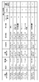
- FIG. 6 is a diagram showing an example of the data format of the provision record information recorded in the provision record DB according to the first embodiment.
- a piece of provision performance information in FIG. 6 includes a relevant time, a management register ID, a household appliance model ID, an individual number, and a provision information amount.
- the relevant time indicates the period including the time when the provision performance information was provided.
- the provided information amount indicates, for each home appliance, the number of times the operation log of the home appliance has been provided in the corresponding time.
- the recording unit 104 records in the usage record DB 107 the operation log transmitted by the communication unit 101 to the user terminal 30 in response to the usage request or the operation log based on the analysis data.
- the recording unit 104 records it in the usage history DB 107 as usage history information. That is, the recording unit 104 associates the user ID and the operation log ID, and records them in the usage record DB 107 as usage record information.
- FIG. 7 is a diagram showing an example of the data format of usage history information recorded in the usage history DB according to the first embodiment.
- One row of the table shown in FIG. 7 indicates one piece of usage record information.
- One piece of usage record information in FIG. 7 includes a user ID, a home appliance usage history ID, a management register ID, and a home appliance model ID.
- the management register change unit 108 changes a specific management register ID in the provision record information based on the change request received by the communication unit 101 .
- a specific management register ID is a management register ID associated with a specific individual number, which is a specific data ID, in the provision record information.
- a specific individual number is data identification information that identifies specific data generated by a specific home appliance.
- the management register change unit 108 converts the first management register ID associated with the first data identification information specifying each of the one or more first data as the first management register ID. Change to a different second management ID.
- the change request in this case is, for example, the first administrator identification information associated with the first data identification information specifying each of the one or more first data generated by the first home appliance, and the second administrator identification. It is a request to change to information.
- FIG. 8 is a diagram showing an example of a data format of a change request according to Embodiment 1.
- FIG. 8 is a diagram showing an example of a data format of a change request according to Embodiment 1.
- One row of the table shown in FIG. 8 indicates one change request.
- One change request in FIG. 8 includes a target home appliance model ID, a current management register ID, and a post-change management register ID.
- the target home appliance model ID is information that specifies the home appliance model for which the management register ID is to be changed.
- the current management register ID indicates the management register ID before the change due to the change request. That is, the current management register ID is an example of the first management register ID (first administrator identification information).
- the post-change management register ID indicates the management register ID after change due to the change request.
- the post-change management register ID is an example of a second management register ID (second administrator identification information).
- One or more data are provided by one or more data providers.
- One or more data providers and one or more data managers are different from each other.
- a specific description will be given below.
- a first data provider owns a first model of a first home appliance and a second model of a second home appliance that is different from the first model
- a second data provider owns a first model of a third home appliance. and a fourth home appliance of the second model.
- the first data manager manages data provided by the first and third home appliances, that is, data provided by the first type of home appliance.
- the second data manager manages the data provided by the second and fourth home appliances, that is, the data provided by the second type of home appliance.
- Connection device 20 9 is a diagram illustrating an example of a configuration of a connection device according to Embodiment 1.
- FIG. 1 is a diagram illustrating an example of a configuration of a connection device according to Embodiment 1.
- the connection device 20 is communicably connected to the home appliances 21 and 22, and an operation log acquired by transmission from the home appliances 21 and 22 or acquired by the connection device 20 connecting to the home appliances 21 and 22. is transmitted to the management server 10 via the network N.
- the connection device 20 may be a router having at least one of a wireless LAN function and a wired LAN function.
- the connection device 20 includes a communication section 201 , a control section 202 and a storage section 203 .
- the connection device 20 can be realized by a processor executing a predetermined program using memory. Each component will be described below.
- the communication unit 201 communicates with the home appliances 21 and 22. Thereby, the communication part 201 acquires the operation log of the household appliances 21 and 22 from the household appliances 21 and 22. FIG. Also, the communication unit 201 communicates with the management server 10 via the network N. FIG. The communication part 201 transmits the operation log acquired from the household appliances 21 and 22 to the management server 10, for example.
- the communication unit 201 may be connected with the home appliances 21 and 22 by wireless communication or may be connected by wired communication.
- the control unit 202 causes the storage unit 203 to store the operation log acquired by the communication unit 201 .
- the control unit 202 may control the timing of acquiring the operation log from the home appliances 21 and 22 by controlling the communication unit 201 .
- the acquisition timing may be every predetermined period, a predetermined time, or a time when a predetermined condition is satisfied.
- the control unit 202 may control the timing of transmitting the operation log stored in the storage unit 203 to the management server 10 by controlling the communication unit 201 .
- the control unit 202 may collectively transmit a plurality of operation logs stored in the storage unit 203 to the management server 10 .
- the transmission timing may be every predetermined period, a predetermined time, or a time when a predetermined condition is satisfied.
- the storage unit 203 stores the operation log acquired by the communication unit 201.
- the storage unit 203 may store information necessary for the operation of the connection device 20, such as programs.
- [Household appliances 21] 10 is a diagram illustrating an example of a configuration of a home appliance according to Embodiment 1.
- FIG. 1 is a diagram illustrating an example of a configuration of a home appliance according to Embodiment 1.
- the home appliance 21 is installed in the residence 40.
- the home appliances 21 are, for example, home appliances such as TVs, recorders, air conditioners, lighting devices, washing machines, refrigerators, and intercoms.
- the home appliance 21 may be household equipment such as a solar power generator, a fuel cell, an electric shutter, a water heater, and an electronic lock.
- the home appliance 21 may be a health care device such as a body composition monitor, a blood pressure monitor, a thermometer, or a wearable terminal.
- the home appliance 21 includes a communication section 211 , a control section 212 , an input reception section 213 , an operation section 214 , a sensor 215 and a storage section 216 .
- the control unit 212 of the home appliance 21 can be implemented by a processor executing a predetermined program using a memory.
- the control part 212 of the household appliance 21 may be implement
- the household appliance 22 since the household appliance 22 has the same configuration as the household appliance 21, a description thereof will be omitted. Each component will be described below.
- the communication unit 211 communicates with the connection device 20.
- the communication unit 211 may communicate with the management server 10 via the network N instead of via the connection device 20 .
- the communication unit 211 transmits the operation log of the home appliance 21 to the connection device 20 .
- the communication unit 211 may be connected to the connection device 20 by wireless communication or may be connected by wired communication.
- the control unit 212 receives content information such as user operation details received by the input receiving unit 213, the operation state of the operation unit 214, the detection result of the sensor 215, the information from the external device received by the communication unit 211, and the home appliance.
- the operation log is generated by associating the home appliance type ID of 21, the individual number of the home appliance 21, and the time when the content information was generated.
- Control unit 212 stores the generated operation log in storage unit 216 .
- the time at which the content information is generated is, for example, the time at which the operation content was accepted, the time at which the operating state changed, the time at which the sensor 215 performed detection, the time at which the sensor 215 performed detection, or the time when the external device is the time the information was received from
- the control unit 212 transmits the operation log stored in the storage unit 216 to the connection device 20 by controlling the communication unit 211 . Further, the control unit 212 may control the timing of transmitting the operation log stored in the storage unit 216 to the connection device 20 by controlling the communication unit 211 . By controlling the communication unit 211 , the control unit 212 may collectively transmit a plurality of operation logs stored in the storage unit 216 to the connection device 20 . The transmission timing may be every predetermined period, a predetermined time, or a time when a predetermined condition is satisfied. Also, the control unit 212 controls the operation of the operation unit 214 .
- the input reception unit 213 receives input from the user.
- the input reception unit 213 is, for example, a switch, and may receive an on/off input of the switch from the user.
- the input reception unit 213 is a remote control receiver, and may receive an operation by the user by receiving an operation signal emitted from the remote control when the user operates the remote control.
- the input reception unit 213 may be a touch pad, touch panel, keyboard, mouse, or the like.
- the operating unit 214 implements the functions of the home appliance 21 .
- the operation unit 214 is, for example, a backlight, a liquid crystal panel, or the like in the case of a liquid crystal TV.
- a liquid crystal panel In the case of an air conditioner, it is a compressor, an expansion valve, a fan, and the like.
- a lighting device it is a light source.
- a washing machine it may be the motor that rotates the drum, or the electronic valve for supplying or draining water.
- it is a refrigerator, it is a compressor, a fan, and the like.
- it is a door phone it is a speaker, a microphone, a monitor, and the like.
- a sensor 215 detects the state of the home appliance 21 .
- the sensor 215 is a temperature sensor, an illuminance sensor, a light detection sensor, or the like.
- the storage unit 216 stores the operation log generated by the control unit 212.
- the storage unit 216 may store information necessary for the operation of the home appliance 21, such as programs.
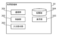
- [User terminal 30] 11 is a diagram illustrating an example of a configuration of a user terminal according to Embodiment 1.
- FIG. 1 is a diagram illustrating an example of a configuration of a user terminal according to Embodiment 1.
- the user terminal 30 transmits a usage request to the management server 10 and acquires from the management server 10 the operation log corresponding to the usage request or the analysis data of the operation log.
- the user terminal 30 may generate analysis data from the operation log and display the generated analysis data on the display unit 305 of the user terminal 30 .
- the user terminal 30 may display the acquired analysis data on the display unit 305 of the user terminal 30 .
- the user terminal 30 is, for example, a computer such as a smart phone, a tablet terminal, or a personal computer.
- the user terminal 30 includes a communication section 301 , a control section 302 , an input reception section 303 , a storage section 304 and a display section 305 .
- the user terminal 30 can be realized by a processor executing a predetermined program using memory. Each component will be described below.
- the communication unit 301 communicates with the management server 10 via the network N. Thereby, the communication unit 301 transmits a usage request to the management server 10 .
- the communication unit 301 also receives the operation log corresponding to the usage request or the analysis data of the operation log from the management server 10 .
- the control unit 302 generates a usage request according to the input received by the input receiving unit 303. After generating the usage request, the control unit 302 controls the communication unit 301 to transmit the generated usage request to the management server 10 . Also, the control unit 302 may generate analysis data according to the operation log received by the communication unit 301 . Also, the control unit 302 may cause the display unit 305 to display the analysis data received by the communication unit 301 .
- FIG. 12 is a diagram showing an example of a data format of a usage request according to Embodiment 1.
- FIG. 12 is a diagram showing an example of a data format of a usage request according to Embodiment 1.
- One row of the table shown in FIG. 12 indicates one usage request.
- One use request in FIG. 12 includes a user ID, application time, and use application content.
- the user ID is user identification information that identifies the user of the user terminal 30.
- the application time is the time when the usage request is generated.
- the usage application content indicates conditions for extracting one or more operation logs desired by the data user from the plurality of operation logs stored in the management server 10 .
- the content of the usage application indicates the conditions for extracting the reservation time from the operation log generated by the washing machine in fiscal year 2020.
- used detergent information after August 2020 conditions for extracting the brand of used detergent from the operation log generated by the washing machine after August 2020 are shown.
- the recording status is 23:00 on November 3, 2020, conditions for extracting the recording status from the operation log generated by the recorder at 23:00 on November 3, 2020 are shown.
- the recording status may include the channel being recorded, the program being recorded, and the like.
- the input reception unit 303 receives input from the user. Also, the input reception unit 303 may be a touch pad, touch panel, keyboard, mouse, or the like.
- the storage unit 304 stores the operation log or analysis data received by the communication unit 301 .
- the communication unit 301 may store information necessary for the operation of the user terminal 30, such as programs.
- the display unit 305 is, for example, a display that displays analysis data.
- [Management register terminal 50] 13 is a diagram illustrating an example of a configuration of a management registered terminal according to Embodiment 1.
- FIG. 1 A diagram illustrating an example of a configuration of a management registered terminal according to Embodiment 1.
- the management terminal 50 generates a change request and transmits the generated change request to the management server 10. This causes the management server 10 to change the management register ID according to the change request.
- the management register terminal 50 may acquire the change result of the management register ID from the management server 10 and display the change result on the display unit 505 of the management register terminal 50 .
- the managed terminal 50 is, for example, a computer such as a smart phone, a tablet terminal, or a personal computer.
- the management register terminal 50 includes a communication section 501 , a control section 502 , an input reception section 503 , a storage section 504 and a display section 505 .
- the management register terminal 50 can be realized by a processor executing a predetermined program using a memory. Each component will be described below.
- the communication unit 501 communicates with the management server 10 via the network N. Thereby, the communication unit 501 transmits the change request to the management server 10 . In addition, the communication unit 501 receives from the management server 10 the change result of the management register ID in response to the change request.
- the control unit 502 generates a change request according to the input received by the input receiving unit 503. After generating the change request, the control unit 502 controls the communication unit 501 to transmit the generated change request to the management server 10 . Also, the control unit 502 may cause the display unit 505 to display the change result received by the communication unit 501 .
- the input reception unit 503 receives input from the user. Also, the input reception unit 503 may be a touch pad, touch panel, keyboard, mouse, or the like.
- the storage unit 504 stores the operation log or analysis data received by the communication unit 501 .
- the communication unit 501 may store information necessary for the operation of the user terminal 30, such as programs.
- the display unit 505 is, for example, a display that displays analysis data.
- the management register terminal 50a is owned by the first data manager and is associated with the first management register ID of the first data manager, and the management register terminal 50b is the second data manager. This is a terminal owned by a second data manager and associated with the second management register ID of the second data manager.
- FIG. 14 shows a first example of displayed analysis data.
- FIG. 15 shows a second example of displayed analysis data.
- FIG. 16 shows a third example of displayed analysis data.
- FIG. 14 is analysis data of a plurality of operation logs extracted by the conditions for extracting the reservation time from the operation logs generated by the washing machine in 2020.
- the analysis data is represented by a histogram, with the horizontal axis representing the reservation time and the vertical axis representing the number of reservations.
- FIG. 15 shows analysis data of a plurality of operation logs extracted by the conditions for extracting the brand of detergent used from among the operation logs generated by the washing machine after August 2020.
- the analysis data is shown as a pie chart showing the usage rate for each detergent brand.
- Detergent brands include detergent manufacturers.
- FIG. 16 is analysis data of a plurality of operation logs extracted according to the conditions for extracting the recording status from among the operation logs generated by the recorder at 23:00 on November 3, 2020.
- the analysis data is shown as a pie chart showing the recording rate for each channel in the recorder.
- FIG. 17 is a flow chart showing incentive determination processing of the management system according to the first embodiment.
- the management server 10 stores provision history information in which data identification information identifying one or more operation logs and administrator identification information identifying one or more data administrators are associated with each other in the provision history DB 106. (S11).
- the management server 10 may further associate and record provider identification information that identifies the data provider.
- the management server 10 may further associate and record value standard information that serves as a standard for calculating the data value of each of the one or more operation logs.
- the management server 10 records, in the usage history DB 107, usage history information including data identification information identifying usage data used by the data user in one or more operation logs (S12).
- the management server 10 determines usage data to be processed based on the usage record DB 107 (S13).
- the management server 10 identifies an operation log associated with the same data identification information as the data identification information of the determined use data to be processed in the provision record DB 106, and manages the identified data.
- the person is specified (S14).
- the management server 10 may further specify the value reference information and the data provider of the specified operation log in the provision record DB 106 .
- the management server 10 determines incentives for the identified data provider based on the identified value standard information (S15).
- FIG. 18 is a sequence diagram showing an example of the record processing (S11) of the provision record information of the management system according to the first embodiment.
- FIG. 18 illustrates the configuration of the home appliances A1 and A2 and the connection device A only in the home A among the homes A to X, and the home appliances B1 to X1 and B2 to X2 and the connection devices B in the other homes B to X. Illustration of the configuration of ⁇ X is omitted.
- the home appliances B1 to X1 and B2 to X2 and the connection devices B to X are assumed to perform the same processing as the home appliances A1 and A2 and the connection device A in the house A only.
- the home appliance A1 transmits an operation log to the connection device A at a predetermined timing (S101).
- the home appliance A2 transmits an operation log to the connection device A at a predetermined timing (S102). Steps S101 and S102 may be performed at the same timing or may be performed at different timings.
- Connection device A stores the received operation log (S103).
- the connection adapter A accumulates operation logs received during a predetermined period, for example.
- connection adapter A transmits the stored operation log to the management server 10 via the network N at a predetermined timing (S104).
- the connection adapter A transmits, for example, one or more operation logs stored during a predetermined period to the management server 10 via the network N.
- the management server 10 stores the received operation log (S105).
- the management server 10 generates provision record information according to the received operation log, and records the provision record information in the provision record DB 106 (S106). Specifically, the management server 10 refers to the management register reference table, identifies the management register ID associated with the home appliance model ID included in the operation log in the management register reference table, Add management register ID. Also, the management server 10 adds value reference information corresponding to the operation log to the operation log. Thereby, the provision record information is generated.
- FIG. 19 is a sequence diagram showing an example of the recording process (S12) of usage history information of the management system according to the first embodiment.
- the user terminal 30 receives an input from the user and generates an operation log usage request (S111).
- the user terminal 30 transmits the generated usage request to the management server 10 via the network N (S112).
- the management server 10 Upon receiving the usage request, the management server 10 identifies one or more operation logs according to the extraction conditions included in the usage request (S113).
- the management server 10 generates analysis data of the identified one or more operation logs (S114).
- the management server 10 transmits the generated analysis data to the user terminal 30 via the network N (S115).
- the user terminal 30 displays the received analysis data (S116).
- the management server 10 After step S115, the management server 10 generates usage record information using the identified one or more operation logs, and records the generated usage record information in the usage record DB 107 (S117).
- the management server 10 may transmit one or more operation logs according to the extraction conditions.
- the user terminal 30 may generate analysis data using one or more operation logs and display the generated analysis data.
- FIG. 20 is a flowchart showing an example of processing for calculating usage fees and incentives according to the first embodiment.
- the management server 10 acquires one or more pieces of usage record information for each user from the usage record DB 107 (S121). For example, as shown in FIG. 7, a plurality of pieces of usage record information with a user ID of A2356 are acquired.
- the management server 10 extracts one or more operation logs from one or more pieces of usage record information acquired for each user (S122).
- the management server 10 acquires, from the provision record DB 106, the value reference information in which the same home appliance use history ID as the home appliance use history ID, which is the data identification information of the extracted one or more operation logs, is associated ( S123).
- the management server 10 determines the data value based on the acquired value standard information (S124). The management server 10 determines the data value of each of the one or more acquired operation logs.
- the management server 10 sums the data value of one or more operation logs extracted from one or more pieces of usage record information for each user, thereby calculating the usage fee for each user. is calculated (S125).
- the management server 10 determines individual incentives for each of the one or more operation logs based on the data value of the one or more operation logs (S126). That is, the management server 10 determines one or more individual incentives respectively corresponding to one or more operation logs.
- the management server 10 aggregates one or more individual incentives for each management register ID (that is, for each data manager) (S127).
- the management server 10 determines individual incentives for each predetermined period and for each management register ID as incentives for each data manager (S128).
- FIG. 21 is a flow chart showing an example of a management register ID change process according to the first embodiment.
- the management server 10 receives a request to change the management register ID from the management register terminal 50 (S131).
- the management server 10 selects the management register ID specified in the change request from among the management register IDs in the management register reference table, the operation log recorded in the usage history DB, the provision record information, and the utilization record information.
- the family ID is changed to another management family ID (S132).
- the request to change the management register ID may be transmitted from the first management register terminal 50a associated with the first management register ID of the change source, or may be transmitted from the first management register ID associated with the second management register ID of the change destination. may be transmitted from the second management registered terminal 50b. Further, step S132 may be executed after an agreement on the change request is made between the first management registered terminal 50a and the second management registered terminal 50b.
- FIG. 22 is a flow chart showing an example of value standard information update processing according to the first embodiment.
- the management server 10 receives a request to update the value standard information from the external device (S141).
- the management server 10 updates the value standard information to the latest information (S142).
- the management server 10 may update the value standard information to the latest information in response to the update request.
- the update request may contain the latest value base information.
- the latest value standard information may be determined by a person, or may be calculated by a computer using a predetermined algorithm.
- the management server 10 may hold a predetermined algorithm for calculating the latest value standard information.
- management server 10 executes an incentive determination method for one or more data administrators who manage data generated by a plurality of home appliances.
- One or more data managers are associated with different models of a plurality of household appliances.
- the management server 10 associates data identification information that identifies each of the one or more data generated by the plurality of home appliances with administrator identification information that identifies each of the one or more data administrators. record the provision performance information. After that, if there is usage data that has been used by the data user among the one or more pieces of data, the management server 10 determines incentives for the data manager who manages the usage data based on the provision record information.
- one or more data are provided by one or more data providers who own multiple home appliances.
- One or more data managers and one or more data providers are different from each other. Therefore, it is possible to determine incentives for data managers different from data providers.
- the first data provider among the one or more data providers includes a first appliance of a first model and a second appliance of a second model different from the first model. and own.
- a second data provider among the one or more data providers owns a first model third home appliance and a second model fourth home appliance.
- a first data manager among the one or more data managers manages data provided by the first home appliance and the third home appliance.
- a second data manager among the one or more data managers manages data provided by the second and fourth home appliances.
- the profit obtained by using the data generated by the first model home appliance can be determined as an incentive for the first data manager, and the data generated by the second model home appliance can be used.
- the profit obtained by being treated can be determined as an incentive for the second data manager. Therefore, the profit obtained by using the data can be appropriately distributed to the data manager.
- the management server 10 further includes a specific Receive change requests to change administrator identities.
- the management server 10 changes specific administrator identification information associated with specific data based on the change request.
- the change request is a first administrator identification associated with first data identification information that identifies each of the one or more first data generated by the first home appliance.
- the first administrator identification information associated with the first data identification information specifying each of the one or more first data is changed to the second administrator identification information based on the change request.
- the first administrator identification information is identification information that identifies the first data administrator among the one or more data administrators.
- the second administrator identification information is identification information that identifies a second data administrator different from the first data administrator among the one or more data administrators.
- the administrator identification information associated with the first data identification information can be easily changed from the first administrator identification information to the second administrator identification information. Therefore, it is possible to easily change the distribution destination of the incentive.
- the management server 10 identifies data associated with the same data identification information as the data identification information that identifies the usage data, based on the provision record information. and identify the data controller that controls the identified data. Then, the management server 10 determines an incentive for the identified data manager based on the value standard information of the identified data.
- (Embodiment 2) 23 is a diagram illustrating an example of a configuration of a management system according to Embodiment 2; FIG.
- the management system according to the second embodiment differs from the management system according to the first embodiment in that it includes a plurality of management servers 11a to 11c.
- management servers 11a to 10c are also referred to as the management server 11 below, the management servers 11a to 11c may also be referred to as the management servers A to C in some cases.
- FIG. 24 is a diagram showing an example configuration of the management server 11 according to the second embodiment.
- the same reference numerals are assigned to the same configurations as in FIG. 2, and detailed description thereof will be omitted.
- the management server 11 shown in FIG. 24 is an example of one server (computer) among a plurality of servers holding distributed ledgers.
- the management server 11 includes a communication unit 101, a value calculation unit 102, a settlement amount determination unit 103, a recording unit 104, a usage history DB 105, a management register change unit 108, and a transaction data generation unit. It comprises a unit 109 , a transaction data verification unit 110 and a distributed ledger 111 .
- the management server 11 can be realized by a processor executing a predetermined program using memory. Each component will be described below.
- the transaction data generation unit 109 generates first transaction data.
- the transaction data generation unit 109 generates first transaction data including the provision record information generated by the recording unit 104 .
- the transaction data generation unit 109 generates second transaction data.
- the transaction data generation unit 109 generates second transaction data including the usage record information generated by the recording unit 104 .
- the transaction data generation unit 109 transmits the generated first transaction data to a plurality of other management servers 11 via the communication unit 101 . Also, the transaction data generation unit 109 transmits the generated second transaction data to a plurality of other management servers 11 via the communication unit 101 .
- the transaction data verification unit 110 verifies the validity of the transaction data when the communication unit 101 receives the transaction data. For example, the transaction data verification unit 110 verifies whether an electronic signature generated by a correct method is added to the transaction data received by the communication unit 101 . Note that this verification may be skipped.
- the transaction data received by the communication unit 101 is either the first transaction data or the second transaction data.
- the transaction data verification unit 110 together with a plurality of other management servers 11, executes a consensus algorithm for agreeing on the validity of transaction data.
- PBFT Practical Byzantine Fault Tolerance
- Known consensus algorithms include, for example, PoW (Proof of Work) or PoS (Proof of Stake).
- PoW Proof of Work
- PoS Proof of Stake
- the transaction data verification unit 110 receives reports indicating whether or not transaction data verification has succeeded from each of the plurality of other management servers 11, and the number of reports is a predetermined number. is exceeded. Then, when the number of reports exceeds a predetermined number, the transaction data verification unit 110 may determine that the validity of the transaction data has been verified by the consensus algorithm.
- the transaction data verification unit 110 When the transaction data verification unit 110 confirms the validity of the transaction data, it causes the recording unit 104 to record the transaction data.
- the transaction data verification unit 110 verifies the correctness of the first transaction data and the second transaction data received by the communication unit 101 .
- the recording unit 104 records the transaction data by including the transaction data whose validity has been verified by the transaction data verification unit 110 in a block and storing it in the distributed ledger 111 .
- the management server 11 in recording to the provision record DB, transfers the first transaction data including the provision record information to the other management server 11, and transfers the first transaction data including the first transaction data. By storing one block in the distributed ledger 111 managed by the management server 11, it is recorded in the provision record DB. Also, in recording to the usage record DB, the management server 11 transfers the second transaction data including the usage record information to another management server 11, and transfers the second block including the second transaction data to the management server 11 By storing it in the distributed ledger 111 managed by , it is recorded in the usage record DB.
- the provision record DB and the use record DB may be stored in the distributed ledger 111 .
- the recording unit 104 may have the distributed ledger 111 configured therein.
- the distributed ledger 111 stores first transaction data and second token transaction data. Also, the distributed ledger 111 stores a contract code for executing the processing for calculating usage fees and incentives described with reference to FIG. 20 .
- FIG. 25 is a sequence diagram showing an example of the record processing (S11) of the provision record information of the management system according to the second embodiment.
- the same reference numerals are assigned to the same processes as in FIG. 18, and detailed description thereof will be omitted.
- FIG. 25 exemplifies the configuration of the home appliances A1, A2 and the connection device A only in the house A among the houses A to X, and the home appliances B1 to X1, B2 in the other houses B to X. . . . X2 and the connection devices B to X are omitted from the illustration.
- the home appliances B1 to X1 and B2 to X2 and the connection devices B to X are assumed to perform the same processing as the home appliances A1 and A2 and the connection device A in the house A only.
- connection adapter A transmits the stored operation log to management server A via network N at a predetermined timing (S104a).
- the connection device A transmits, for example, one or more operation logs stored during a predetermined period to the management server A via the network N.
- the management server A generates provision performance information including the received operation log, management register ID, and value standard information, and generates first transaction data including the provision performance information (S105a). Note that in FIG. 25, the first transaction data is denoted as first Tx.
- management server A transmits the generated first transaction data to other management servers B and C (S106a).
- the management servers A to C execute the consensus algorithm, generate a block containing the first transaction data, and store it in the distributed ledger 111 (S107a).
- the provision record information included in the first transaction data is stored in the provision record DB.
- the first transaction data may be generated by the connection device A.
- the connection device A transmits the first transaction data to the management server A, and the management server A transfers the received first transaction data to the other management servers B and C. This may start step S107a.
- FIG. 26 is a sequence diagram showing an example of the record processing (S12) of usage record information of the management system.
- S12 record processing
- management server A After step S114, management server A generates usage record information using the identified one or more operation logs, and generates second transaction data including the generated usage record information (S117a). Note that in FIG. 26, the second transaction data is denoted as second Tx.
- management server A transmits the generated second transaction data to other management servers B and C (S118a).
- the management servers A to C execute the consensus algorithm, generate a block containing the second transaction data, and store it in the distributed ledger 111 (S119a).
- the usage history information included in the second transaction data is stored in the usage history DB.
- each of the management servers A to C executes usage fee and incentive calculation processing using the smart contract (S120a).
- the processing for calculating usage fees and incentives is the same as the processing described with reference to FIG. 20, so detailed description thereof will be omitted.
- the process of step S120a is described as settlement process.
- each of the plurality of distributed ledgers 111 held by management servers A to C includes contract code for identifying data managers and determining incentives based on the second transaction data. Then, when the management servers A to C acquire the second transaction data in identifying the data manager and determining incentives, the management servers A to C execute the contract code included in the distributed ledger 111 of the management server A to perform data management. identify and determine incentives;
- the management server 11 further records the provision record information in the provision record database.
- the management server 10 records usage history information including data identification information for specifying usage data in the usage history database.
- the management server 10 transfers the first transaction data including the provision record information to the other computer, and the computer manages the first block including the first transaction data in the record in the provision record database. By storing it in a distributed ledger, it will be recorded in the provision performance database.
- the management server 10 transfers the second transaction data including the usage record information to another computer, and the computer manages the second block including the second transaction data in the recording to the usage record database. By storing it in the distributed ledger, it is recorded in the usage record database.
- the management server 11 identifies a data manager and provides incentives based on the second transaction data for each of a plurality of distributed ledgers held by computers and other computers. Contains contract code for making decisions. The identification of data custodians and the determination of incentives are performed by obtaining second transaction data and executing contract code contained in a computer's distributed ledger.
- the provision performance information further includes a hash value of data.
- the provided performance information stored in the distributed ledger contains a hash value instead of the data, so the data can be prevented from being disclosed.
- the management server 10 may further determine incentives for data providers.
- the incentive for the data provider determined in this case may be paid from the data controller to the data provider.
- An incentive determination method is a computer-implemented incentive determination method for one or more data providers that provide data generated by a home appliance, wherein each of the one or more data providers data identification information identifying each of the one or more provided data provided by the one or more data providers; and criteria for calculating the data value of each of the one or more provided data is recorded, and when there is usage data used by a data user among the one or more provided data, the usage data based on the provision performance information and the value standard information includes an index value determined by each of a plurality of value indices.
- each of a plurality of value indicators associated with the provided data Based on the index value specified in 1., determine the incentive for the data provider of the provided data.
- provided data is associated with an index value determined by each of a plurality of value indices, so that the data value of provided data can be determined in advance using a plurality of value indices.
- the index values determined for each of the multiple value indicators are associated, even if one value indicator is biased, the bias can be reduced, and the data value of the provided data can be adjusted to an appropriate value. can decide. Therefore, the incentive for the data provider can be appropriately determined, and the provider can be urged to provide the provided data. Therefore, data can be efficiently collected.
- determining the incentive based on the provision performance information, provided data associated with the same data identification information as data identification information specifying the used data is specified, and value standard information of the specified provided data is specified. and a data provider who provided the identified provided data may be identified, and an incentive for the identified data provider may be determined based on the identified value standard information.
- record usage record information including data identification information specifying the usage data in a usage record database, specify the number of uses of the specified provided data based on the use record database, and determine the incentive Then, an incentive for the specified data provider may be determined based on the specified value standard information and the specified number of times of use.
- the plurality of value indices in the value standard information are a value index based on the type of the provided data, a value index based on the type of home appliance that generated the provided data, and a value index based on the home appliance that generated the provided data. At least two of the time-based value indicators may be included.
- the provided past record information is recorded in a provided past record database, and in the recording in the provided past record database, the computer transfers the first transaction data including the provided past record information to another computer, and By storing the first block containing the first transaction data in a distributed ledger managed by the computer, it is recorded in the provision record database, and in the recording in the use record database, the computer stores the use record information. may be recorded in the usage history database by transferring the second transaction data including the good.
- each of the plurality of distributed ledgers owned by the computer and the other computers identifies the value standard information and the data provider and determines the incentive based on the second transaction data. wherein, upon obtaining the second transaction data, executing the contract code contained in the distributed ledger of the computer in identifying the value base information and the data provider and determining the incentive By doing so, the identification of the value reference information and the data provider, and the determination of the incentive may be performed.
- the provision performance information may further include a hash value of the provided data.
- determining the incentive based on an index value determined by each of the plurality of value indicators included in the specified value standard information and values pre-associated with each of the plurality of value indicators , calculating the value of the usage data for each of the usage data, determining the incentive based on the calculated value of the usage data, wherein the pre-associated value is determined so as to change over time;
- the computer transfers third transaction data containing the determined pre-associated value to another computer, and transfers a third block containing the third transaction data to a distributed ledger managed by the computer. may be stored.
- a server is a server that determines incentives for one or more data providers that provide data generated by a home appliance, and includes a processor and a memory, wherein the processor , using the memory, provider identification information that identifies each of the one or more data providers; and data identification information that identifies each of the one or more provided data provided by the one or more data providers; , value standard information that serves as a basis for calculating the data value of each of the one or more provided data, and record provision performance information that is associated with each other, and use of the one or more provided data by the data user If there is data, an incentive for the data provider who provided the usage data is determined based on the provision performance information, and the value standard information includes an index value determined by each of a plurality of value indices.
- the operation log of home appliances was given as a specific example of data, but it is not limited to the operation log of home appliances.
- the data may be, for example, an operation log of an automatic driving vehicle, or an operation log of equipment provided in a facility such as a factory.
- the data may also be measured values of a power meter, a gas meter, or a water meter installed in a house.
- a function of recording an operation log in the usage history DB 105 and the usage history DB 105 a function of recording provision history information in the provision history DB 106 and the provision history DB 106, and a usage history DB 107 and the usage history
- the function of recording usage record information in the DB 107 may be implemented as a device separate from the management server 10 . These devices need only be communicably connected to the management server 10 .
- the data value may be changed due to the following factors.
- the data value may fluctuate depending on the reliability of the appliance that generated the operation log.
- the reliability of a home appliance may be determined based on, for example, the OS type, OS update history, external operation history, external communication history, application installation history, and the like.
- OS update records, external operation records, external communication records, application installation records, and the like may be written and managed in databases provided in the management servers 10 and 11 .
- the reliability of the home appliance may be determined using a reliability evaluation table in which the reliability is associated with each of the above achievements.
- the reliability of a home appliance may be evaluated by combining a plurality of achievements.
- the reliability of each operation log may be determined based on the reliability of the home appliance.
- the management servers 10 and 11 may calculate the data value with reliability by multiplying the data value with the determined reliability, and determine usage fees or incentives based on the data value with reliability.
- the calculation of the data value may be performed based on other factors. For example, when a specific request such as "I want this kind of data" is received from the user terminal 30, the data value may be calculated so that the more requested operation log has a higher value.
- Request information indicating a request may be recorded in a database provided in the management servers 10 and 11 . Further, in the usage history DB 105, information indicating whether or not there is a request may be added, and whether or not there is a request may be recorded in association with the operation log.
- the value of data varies depending on the type of operation log, the model of the home appliance that generated the operation log, seasonal fluctuations, etc., but it is not limited to this.
- the data value may be determined by data related to the family structure of the provider's home (hereinafter referred to as "used family attribute data").
- the family attribute data to be used includes personal data such as age, sex, height, weight, occupation, commuting place, income amount, etc., which are family attributes to be used.
- the used family attribute data may be recorded in the used family attribute database provided in the management servers 10 and 11 as a set of the household ID and the used family attribute data.
- the data value may change depending on the activity log related to households with certain specified family attributes.
- a column of "family attribute evaluation" may be provided and managed in the home appliance use history database.
- the value of the operation log generated from the home of the family with the family attribute that has many requests is received.
- the data value may be calculated so as to be higher than the value of the operation log generated from the residence of the family attribute family with few requests.
- Request information indicating a request may be recorded in a database provided in the management servers 10 and 11 . Further, in the usage history DB 105, information indicating whether or not there is a request for family attributes may be added, and whether or not there is a request for family attributes may be recorded in association with the operation log.
- the data value may be determined by the number of transactions.
- the data value may be calculated such that the value of the action log requested more frequently from the user terminal 30 is higher than the value of the action log requested less frequently.
- the number of transactions may be recorded in a distributed ledger using a block chain so that the user can refer to it using the user terminal 30 while preventing falsification.
- the operation log stored in the usage history DB 105 may be provided to the user terminal 30 when the number of requests from the user terminal 30 exceeds a predetermined threshold. As a result, only operation logs with increased data value are provided.
- the processing to be provided after the number of requests for the operation log stored in the usage history DB 105 exceeds the threshold may be implemented by a blockchain smart contract.
- the value of a newly added operation log may be set higher than the operation log requested by the user terminal 30 more frequently.
- the operation log may be provided only to the user terminal 30 that has evaluated the value of the operation log highly (in the form of an auction).
- the provision record information and the use record information are recorded and managed in the distributed ledger. may be recorded and managed.
- the usage fee and incentive determined by the settlement amount determination unit 103 may be recorded in a centralized database provided in the management server 10, or recorded in a distributed ledger using blockchain provided in the management servers 11a to 11c. may be
- the collection of usage fees from users or the payment of incentives to administrators may be conducted using blockchain-based cryptocurrency.
- Devices forming a blockchain may include all or part of the connection device 20 and the user terminal 30 in addition to the management servers 11a to 11c.
- blocks containing transaction data including operation logs may be recorded in the usage history DB by being stored in the distributed ledger.
- the management server 11 converts only operation logs with a degree of privacy relation greater than a predetermined threshold value (for example, 1) into hash values, and converts the operation logs into hash values, and provides the provided performance information including only the hash values of the operation logs. It may be recorded in the distributed ledger as the performance log provision information. Thereby, the user's privacy can be protected in the management server 11 holding the distributed ledger.
- a predetermined threshold value for example, 1
- operation logs are transmitted from the home appliances 21 and 22 provided in each house 40 to the management servers 10 and 11 through the connection device 20 .
- the provider of the operation log is the owner of each house 40, but it is not limited to this.
- the provider of the operation log may be the installer of the connection device 20 or, if the house 40 is a rental house, the owner of the rental house.
- the facility may be a corporation or organization that owns the facilities such as factories, companies, and warehouses.
- the provider identification information may be the owner ID.
- Each device in the above embodiment is specifically a computer system composed of a microprocessor, ROM, RAM, hard disk unit, display unit, keyboard, mouse, and the like.
- a computer program is recorded in the RAM or hard disk unit.
- Each device achieves its function by the microprocessor operating according to the computer program.
- the computer program is constructed by combining a plurality of instruction codes indicating instructions to the computer in order to achieve a predetermined function.
- a system LSI is an ultra-multifunctional LSI manufactured by integrating multiple components on a single chip. Specifically, it is a computer system that includes a microprocessor, ROM, RAM, etc. . A computer program is recorded in the RAM. The system LSI achieves its functions by the microprocessor operating according to the computer program.
- each part of the constituent elements constituting each of the devices described above may be individually integrated into one chip, or may be integrated into one chip so as to include part or all of them.
- system LSI may also be called IC, LSI, super LSI, or ultra LSI depending on the degree of integration.
- the method of circuit integration is not limited to LSI, and may be realized by a dedicated circuit or a general-purpose processor.
- An FPGA Field Programmable Gate Array
- a reconfigurable processor that can reconfigure the connections and settings of the circuit cells inside the LSI may be used.
- the IC card or module is a computer system composed of a microprocessor, ROM, RAM and the like.
- the IC card or the module may include the super multifunctional LSI.
- the IC card or the module achieves its function by the microprocessor operating according to the computer program. This IC card or this module may be tamper resistant.
- the present disclosure may be the method shown above. Moreover, it may be a computer program for realizing these methods by a computer, or it may be a digital signal composed of the computer program.
- the present disclosure includes a computer-readable recording medium for the computer program or the digital signal, such as a flexible disk, hard disk, CD-ROM, MO, DVD, DVD-ROM, DVD-RAM, BD (Blu-ray (Registered Trademark) Disc), semiconductor memory, or the like. Moreover, it may be the digital signal recorded on these recording media.
- a computer-readable recording medium for the computer program or the digital signal such as a flexible disk, hard disk, CD-ROM, MO, DVD, DVD-ROM, DVD-RAM, BD (Blu-ray (Registered Trademark) Disc), semiconductor memory, or the like.
- BD Blu-ray (Registered Trademark) Disc
- semiconductor memory or the like.
- it may be the digital signal recorded on these recording media.
- the computer program or the digital signal may be transmitted via an electric communication line, a wireless or wired communication line, a network represented by the Internet, data broadcasting, or the like.
- the present disclosure may also be a computer system comprising a microprocessor and memory, the memory storing the computer program, and the microprocessor operating according to the computer program.
- the present disclosure can be used for incentive determination methods, servers, and programs, and can be used for incentive determination methods, servers, programs, and the like that can efficiently collect data.
Landscapes
- Engineering & Computer Science (AREA)
- Business, Economics & Management (AREA)
- Finance (AREA)
- Accounting & Taxation (AREA)
- Development Economics (AREA)
- Strategic Management (AREA)
- Theoretical Computer Science (AREA)
- Physics & Mathematics (AREA)
- General Physics & Mathematics (AREA)
- Entrepreneurship & Innovation (AREA)
- Economics (AREA)
- Marketing (AREA)
- General Business, Economics & Management (AREA)
- Computer Security & Cryptography (AREA)
- Databases & Information Systems (AREA)
- Data Mining & Analysis (AREA)
- Game Theory and Decision Science (AREA)
- Computer Networks & Wireless Communication (AREA)
- Signal Processing (AREA)
- General Engineering & Computer Science (AREA)
- Management, Administration, Business Operations System, And Electronic Commerce (AREA)
Abstract
Priority Applications (3)
| Application Number | Priority Date | Filing Date | Title |
|---|---|---|---|
| CN202280037551.8A CN117396911A (zh) | 2021-06-03 | 2022-05-31 | 激励决定方法、服务器及程序 |
| JP2023525876A JPWO2022255386A1 (fr) | 2021-06-03 | 2022-05-31 | |
| US18/521,060 US20240095287A1 (en) | 2021-06-03 | 2023-11-28 | Method, server, and recording medium |
Applications Claiming Priority (2)
| Application Number | Priority Date | Filing Date | Title |
|---|---|---|---|
| US202163196348P | 2021-06-03 | 2021-06-03 | |
| US63/196,348 | 2021-06-03 |
Related Child Applications (1)
| Application Number | Title | Priority Date | Filing Date |
|---|---|---|---|
| US18/521,060 Continuation US20240095287A1 (en) | 2021-06-03 | 2023-11-28 | Method, server, and recording medium |
Publications (1)
| Publication Number | Publication Date |
|---|---|
| WO2022255386A1 true WO2022255386A1 (fr) | 2022-12-08 |
Family
ID=84323458
Family Applications (1)
| Application Number | Title | Priority Date | Filing Date |
|---|---|---|---|
| PCT/JP2022/022218 WO2022255386A1 (fr) | 2021-06-03 | 2022-05-31 | Procédé de détermination de mesure d'incitation, serveur et programme |
Country Status (4)
| Country | Link |
|---|---|
| US (1) | US20240095287A1 (fr) |
| JP (1) | JPWO2022255386A1 (fr) |
| CN (1) | CN117396911A (fr) |
| WO (1) | WO2022255386A1 (fr) |
Citations (5)
| Publication number | Priority date | Publication date | Assignee | Title |
|---|---|---|---|---|
| JP2002117183A (ja) * | 2000-10-11 | 2002-04-19 | Mitsubishi Electric Corp | 物資消費量関連サービス装置及び方法 |
| JP2015099492A (ja) * | 2013-11-19 | 2015-05-28 | 株式会社日立製作所 | 報酬分配システムおよび分配管理装置 |
| WO2020184580A1 (fr) * | 2019-03-11 | 2020-09-17 | 株式会社博報堂Dyホールディングス | Dispositif de médiation, système et programme informatique |
| WO2021059434A1 (fr) * | 2019-09-26 | 2021-04-01 | 株式会社日立製作所 | Système de circulation d'informations, procédé de circulation d'informations et support d'enregistrement |
| WO2021100831A1 (fr) * | 2019-11-21 | 2021-05-27 | パナソニック インテレクチュアル プロパティ コーポレーション オブ アメリカ | Procédé de commande, dispositif et programme |
-
2022
- 2022-05-31 JP JP2023525876A patent/JPWO2022255386A1/ja active Pending
- 2022-05-31 CN CN202280037551.8A patent/CN117396911A/zh active Pending
- 2022-05-31 WO PCT/JP2022/022218 patent/WO2022255386A1/fr active Application Filing
-
2023
- 2023-11-28 US US18/521,060 patent/US20240095287A1/en active Pending
Patent Citations (5)
| Publication number | Priority date | Publication date | Assignee | Title |
|---|---|---|---|---|
| JP2002117183A (ja) * | 2000-10-11 | 2002-04-19 | Mitsubishi Electric Corp | 物資消費量関連サービス装置及び方法 |
| JP2015099492A (ja) * | 2013-11-19 | 2015-05-28 | 株式会社日立製作所 | 報酬分配システムおよび分配管理装置 |
| WO2020184580A1 (fr) * | 2019-03-11 | 2020-09-17 | 株式会社博報堂Dyホールディングス | Dispositif de médiation, système et programme informatique |
| WO2021059434A1 (fr) * | 2019-09-26 | 2021-04-01 | 株式会社日立製作所 | Système de circulation d'informations, procédé de circulation d'informations et support d'enregistrement |
| WO2021100831A1 (fr) * | 2019-11-21 | 2021-05-27 | パナソニック インテレクチュアル プロパティ コーポレーション オブ アメリカ | Procédé de commande, dispositif et programme |
Also Published As
| Publication number | Publication date |
|---|---|
| US20240095287A1 (en) | 2024-03-21 |
| JPWO2022255386A1 (fr) | 2022-12-08 |
| CN117396911A (zh) | 2024-01-12 |
Similar Documents
| Publication | Publication Date | Title |
|---|---|---|
| US10255644B2 (en) | System and method for identifying power usage issues | |
| Ali et al. | A data-driven approach to optimize urban scale energy retrofit decisions for residential buildings | |
| JP4060095B2 (ja) | 太陽光発電管理サーバ、太陽光発電管理システム、太陽光発電管理方法およびその方法を実現するプログラムを記録した機械読取可能な記録媒体 | |
| US11468375B2 (en) | System for energy consumption prediction | |
| US11469913B2 (en) | Data collection server, data utilization server and equipment based on use frequency among a plurality of storage corresponding to different levels of use | |
| US11429075B2 (en) | System, apparatus and method for energy management, for usage by consumers of energy from electric utility service providers, and monitoring and management of same | |
| US20090313081A1 (en) | Computer implemented systems and methods for start-up, calibration and troubleshooting of an installed renewable energy system | |
| US11410219B2 (en) | Methods, systems, apparatuses and devices for matching at least one utility consumer to at least one utility provider | |
| US8504668B2 (en) | System and method for managing delivery of public services | |
| WO2012051403A2 (fr) | Marché électronique de l'énergie | |
| WO2014171104A1 (fr) | Procédé de présentation d'informations, système de présentation d'informations, programme et support d'enregistrement | |
| KR20190055264A (ko) | 애플리케이션별 자원 사용량 정보의 제공 기법 | |
| CN102136102A (zh) | 针对消费者能源消耗的分析 | |
| JP2003150732A (ja) | 設備保守業務支援方法および保守業務支援サーバ | |
| US20210125129A1 (en) | Methods and system for generating at least one utility fingerprint associated with at least one premises | |
| KR102468114B1 (ko) | 플랫폼을 가지는 게이트웨이를 이용한 전기차 충전 시스템 및 방법 | |
| JPWO2020122039A1 (ja) | データ管理方法、データ管理システム及びプログラム | |
| WO2022255386A1 (fr) | Procédé de détermination de mesure d'incitation, serveur et programme | |
| WO2022107658A1 (fr) | Procédé de détermination de mesure d'incitation, serveur, et programme | |
| US20020010624A1 (en) | Advertisement providing method and system therefor | |
| EP2746886A2 (fr) | Prédiction d'une panne d'un appareil en utilisant les données relatives à la puissance/énergie cumulée | |
| Svehla | A Specification for Measuring Domestic Energy Demand Profiles | |
| JP5731077B2 (ja) | 情報管理方法 | |
| US20170330246A1 (en) | System, user managing server, and method of providing user customized advertisement | |
| JP7195101B2 (ja) | データ提供システム、計測装置、中継装置、データ提供サーバ、データ提供方法、及び、プログラム |
Legal Events
| Date | Code | Title | Description |
|---|---|---|---|
| 121 | Ep: the epo has been informed by wipo that ep was designated in this application |
Ref document number: 22816132 Country of ref document: EP Kind code of ref document: A1 |
|
| WWE | Wipo information: entry into national phase |
Ref document number: 202280037551.8 Country of ref document: CN |
|
| WWE | Wipo information: entry into national phase |
Ref document number: 2023525876 Country of ref document: JP |
|
| NENP | Non-entry into the national phase |
Ref country code: DE |
|
| 122 | Ep: pct application non-entry in european phase |
Ref document number: 22816132 Country of ref document: EP Kind code of ref document: A1 |