WO2022255385A1 - Sub-micron thin film made of ultra-high molecular weight polyethylene and method for manufacturing same - Google Patents
Sub-micron thin film made of ultra-high molecular weight polyethylene and method for manufacturing same Download PDFInfo
- Publication number
- WO2022255385A1 WO2022255385A1 PCT/JP2022/022217 JP2022022217W WO2022255385A1 WO 2022255385 A1 WO2022255385 A1 WO 2022255385A1 JP 2022022217 W JP2022022217 W JP 2022022217W WO 2022255385 A1 WO2022255385 A1 WO 2022255385A1
- Authority
- WO
- WIPO (PCT)
- Prior art keywords
- film
- molecular weight
- thin film
- melt
- weight polyethylene
- Prior art date
Links
- 229920000785 ultra high molecular weight polyethylene Polymers 0.000 title claims abstract description 201
- 239000004699 Ultra-high molecular weight polyethylene Substances 0.000 title claims abstract description 200
- 239000010409 thin film Substances 0.000 title claims abstract description 143
- 238000004519 manufacturing process Methods 0.000 title claims abstract description 31
- 238000000034 method Methods 0.000 title abstract description 47
- 239000010408 film Substances 0.000 claims abstract description 243
- 238000002844 melting Methods 0.000 claims description 76
- 230000008018 melting Effects 0.000 claims description 76
- IJGRMHOSHXDMSA-UHFFFAOYSA-N Atomic nitrogen Chemical compound N#N IJGRMHOSHXDMSA-UHFFFAOYSA-N 0.000 claims description 40
- 238000001816 cooling Methods 0.000 claims description 36
- 239000002994 raw material Substances 0.000 claims description 35
- 239000000843 powder Substances 0.000 claims description 30
- 238000012360 testing method Methods 0.000 claims description 27
- 229910052757 nitrogen Inorganic materials 0.000 claims description 20
- 238000000465 moulding Methods 0.000 claims description 19
- 230000035699 permeability Effects 0.000 claims description 19
- 238000002360 preparation method Methods 0.000 claims description 18
- 239000000155 melt Substances 0.000 claims description 13
- 238000002834 transmittance Methods 0.000 description 41
- 230000000052 comparative effect Effects 0.000 description 33
- 238000005259 measurement Methods 0.000 description 16
- 239000004698 Polyethylene Substances 0.000 description 14
- 229910052782 aluminium Inorganic materials 0.000 description 13
- XAGFODPZIPBFFR-UHFFFAOYSA-N aluminium Chemical compound [Al] XAGFODPZIPBFFR-UHFFFAOYSA-N 0.000 description 13
- -1 polyethylene Polymers 0.000 description 13
- 229920000573 polyethylene Polymers 0.000 description 12
- 230000008569 process Effects 0.000 description 12
- 239000013078 crystal Substances 0.000 description 11
- 239000000463 material Substances 0.000 description 9
- 230000008602 contraction Effects 0.000 description 8
- 239000000126 substance Substances 0.000 description 7
- 229920001577 copolymer Polymers 0.000 description 6
- NNBZCPXTIHJBJL-UHFFFAOYSA-N decalin Chemical compound C1CCCC2CCCCC21 NNBZCPXTIHJBJL-UHFFFAOYSA-N 0.000 description 6
- 238000010438 heat treatment Methods 0.000 description 6
- 239000000203 mixture Substances 0.000 description 6
- 229920000642 polymer Polymers 0.000 description 6
- 239000002904 solvent Substances 0.000 description 6
- VGGSQFUCUMXWEO-UHFFFAOYSA-N Ethene Chemical compound C=C VGGSQFUCUMXWEO-UHFFFAOYSA-N 0.000 description 4
- 239000005977 Ethylene Substances 0.000 description 4
- 230000004888 barrier function Effects 0.000 description 4
- 239000003054 catalyst Substances 0.000 description 4
- 238000005227 gel permeation chromatography Methods 0.000 description 4
- 230000013011 mating Effects 0.000 description 4
- 239000012528 membrane Substances 0.000 description 4
- 229920001721 polyimide Polymers 0.000 description 4
- 125000001424 substituent group Chemical group 0.000 description 4
- 125000000217 alkyl group Chemical group 0.000 description 3
- 239000003963 antioxidant agent Substances 0.000 description 3
- 238000007664 blowing Methods 0.000 description 3
- BXKDSDJJOVIHMX-UHFFFAOYSA-N edrophonium chloride Chemical compound [Cl-].CC[N+](C)(C)C1=CC=CC(O)=C1 BXKDSDJJOVIHMX-UHFFFAOYSA-N 0.000 description 3
- 239000004615 ingredient Substances 0.000 description 3
- 229940057995 liquid paraffin Drugs 0.000 description 3
- 239000002245 particle Substances 0.000 description 3
- 229910001220 stainless steel Inorganic materials 0.000 description 3
- 239000010935 stainless steel Substances 0.000 description 3
- 239000000758 substrate Substances 0.000 description 3
- 238000009864 tensile test Methods 0.000 description 3
- PXXNTAGJWPJAGM-UHFFFAOYSA-N vertaline Natural products C1C2C=3C=C(OC)C(OC)=CC=3OC(C=C3)=CC=C3CCC(=O)OC1CC1N2CCCC1 PXXNTAGJWPJAGM-UHFFFAOYSA-N 0.000 description 3
- VXNZUUAINFGPBY-UHFFFAOYSA-N 1-Butene Chemical compound CCC=C VXNZUUAINFGPBY-UHFFFAOYSA-N 0.000 description 2
- LIKMAJRDDDTEIG-UHFFFAOYSA-N 1-hexene Chemical compound CCCCC=C LIKMAJRDDDTEIG-UHFFFAOYSA-N 0.000 description 2
- KWKAKUADMBZCLK-UHFFFAOYSA-N 1-octene Chemical compound CCCCCCC=C KWKAKUADMBZCLK-UHFFFAOYSA-N 0.000 description 2
- WSSSPWUEQFSQQG-UHFFFAOYSA-N 4-methyl-1-pentene Chemical compound CC(C)CC=C WSSSPWUEQFSQQG-UHFFFAOYSA-N 0.000 description 2
- LYCAIKOWRPUZTN-UHFFFAOYSA-N Ethylene glycol Chemical compound OCCO LYCAIKOWRPUZTN-UHFFFAOYSA-N 0.000 description 2
- VYPSYNLAJGMNEJ-UHFFFAOYSA-N Silicium dioxide Chemical compound O=[Si]=O VYPSYNLAJGMNEJ-UHFFFAOYSA-N 0.000 description 2
- ATJFFYVFTNAWJD-UHFFFAOYSA-N Tin Chemical compound [Sn] ATJFFYVFTNAWJD-UHFFFAOYSA-N 0.000 description 2
- 230000005540 biological transmission Effects 0.000 description 2
- 230000008859 change Effects 0.000 description 2
- 239000003795 chemical substances by application Substances 0.000 description 2
- 230000007423 decrease Effects 0.000 description 2
- 238000001514 detection method Methods 0.000 description 2
- 238000010586 diagram Methods 0.000 description 2
- 239000010432 diamond Substances 0.000 description 2
- 238000009826 distribution Methods 0.000 description 2
- 230000000694 effects Effects 0.000 description 2
- 239000000835 fiber Substances 0.000 description 2
- 230000004927 fusion Effects 0.000 description 2
- 239000007789 gas Substances 0.000 description 2
- 229910052738 indium Inorganic materials 0.000 description 2
- APFVFJFRJDLVQX-UHFFFAOYSA-N indium atom Chemical compound [In] APFVFJFRJDLVQX-UHFFFAOYSA-N 0.000 description 2
- 230000007246 mechanism Effects 0.000 description 2
- 239000012299 nitrogen atmosphere Substances 0.000 description 2
- 239000003960 organic solvent Substances 0.000 description 2
- 230000000704 physical effect Effects 0.000 description 2
- 238000012545 processing Methods 0.000 description 2
- 239000004711 α-olefin Substances 0.000 description 2
- GBDZXPJXOMHESU-UHFFFAOYSA-N 1,2,3,4-tetrachlorobenzene Chemical compound ClC1=CC=C(Cl)C(Cl)=C1Cl GBDZXPJXOMHESU-UHFFFAOYSA-N 0.000 description 1
- RELMFMZEBKVZJC-UHFFFAOYSA-N 1,2,3-trichlorobenzene Chemical compound ClC1=CC=CC(Cl)=C1Cl RELMFMZEBKVZJC-UHFFFAOYSA-N 0.000 description 1
- 229920006448 PE-UHMW Polymers 0.000 description 1
- 206010034650 Peritoneal adhesions Diseases 0.000 description 1
- 235000006629 Prosopis spicigera Nutrition 0.000 description 1
- 240000000037 Prosopis spicigera Species 0.000 description 1
- 238000005299 abrasion Methods 0.000 description 1
- 239000006096 absorbing agent Substances 0.000 description 1
- 230000001133 acceleration Effects 0.000 description 1
- 239000000654 additive Substances 0.000 description 1
- 239000003242 anti bacterial agent Substances 0.000 description 1
- 239000003429 antifungal agent Substances 0.000 description 1
- 229940121375 antifungal agent Drugs 0.000 description 1
- 230000003078 antioxidant effect Effects 0.000 description 1
- 239000002216 antistatic agent Substances 0.000 description 1
- 238000005266 casting Methods 0.000 description 1
- 239000003086 colorant Substances 0.000 description 1
- 238000012937 correction Methods 0.000 description 1
- 238000004132 cross linking Methods 0.000 description 1
- 238000009792 diffusion process Methods 0.000 description 1
- 238000010894 electron beam technology Methods 0.000 description 1
- 238000005516 engineering process Methods 0.000 description 1
- 230000007613 environmental effect Effects 0.000 description 1
- 238000011156 evaluation Methods 0.000 description 1
- 230000001747 exhibiting effect Effects 0.000 description 1
- 239000000945 filler Substances 0.000 description 1
- 239000003063 flame retardant Substances 0.000 description 1
- 239000004088 foaming agent Substances 0.000 description 1
- 239000011521 glass Substances 0.000 description 1
- 239000012760 heat stabilizer Substances 0.000 description 1
- 238000000265 homogenisation Methods 0.000 description 1
- WGCNASOHLSPBMP-UHFFFAOYSA-N hydroxyacetaldehyde Natural products OCC=O WGCNASOHLSPBMP-UHFFFAOYSA-N 0.000 description 1
- 230000001771 impaired effect Effects 0.000 description 1
- 239000004611 light stabiliser Substances 0.000 description 1
- 229920000092 linear low density polyethylene Polymers 0.000 description 1
- 239000004707 linear low-density polyethylene Substances 0.000 description 1
- 229920001684 low density polyethylene Polymers 0.000 description 1
- 239000004702 low-density polyethylene Substances 0.000 description 1
- 239000000314 lubricant Substances 0.000 description 1
- 229920002521 macromolecule Polymers 0.000 description 1
- 238000000691 measurement method Methods 0.000 description 1
- 239000012968 metallocene catalyst Substances 0.000 description 1
- 238000002156 mixing Methods 0.000 description 1
- 238000012986 modification Methods 0.000 description 1
- 230000004048 modification Effects 0.000 description 1
- TVMXDCGIABBOFY-UHFFFAOYSA-N n-Octanol Natural products CCCCCCCC TVMXDCGIABBOFY-UHFFFAOYSA-N 0.000 description 1
- 239000002667 nucleating agent Substances 0.000 description 1
- SSDSCDGVMJFTEQ-UHFFFAOYSA-N octadecyl 3-(3,5-ditert-butyl-4-hydroxyphenyl)propanoate Chemical compound CCCCCCCCCCCCCCCCCCOC(=O)CCC1=CC(C(C)(C)C)=C(O)C(C(C)(C)C)=C1 SSDSCDGVMJFTEQ-UHFFFAOYSA-N 0.000 description 1
- 239000002530 phenolic antioxidant Substances 0.000 description 1
- 239000000049 pigment Substances 0.000 description 1
- 239000004014 plasticizer Substances 0.000 description 1
- 238000006116 polymerization reaction Methods 0.000 description 1
- 229920000098 polyolefin Polymers 0.000 description 1
- 238000003672 processing method Methods 0.000 description 1
- QQONPFPTGQHPMA-UHFFFAOYSA-N propylene Natural products CC=C QQONPFPTGQHPMA-UHFFFAOYSA-N 0.000 description 1
- 125000004805 propylene group Chemical group [H]C([H])([H])C([H])([*:1])C([H])([H])[*:2] 0.000 description 1
- 230000005855 radiation Effects 0.000 description 1
- 238000011084 recovery Methods 0.000 description 1
- 239000012925 reference material Substances 0.000 description 1
- 239000000377 silicon dioxide Substances 0.000 description 1
- 238000002145 thermally induced phase separation Methods 0.000 description 1
- 238000003852 thin film production method Methods 0.000 description 1
- 238000007740 vapor deposition Methods 0.000 description 1
- XLYOFNOQVPJJNP-UHFFFAOYSA-N water Substances O XLYOFNOQVPJJNP-UHFFFAOYSA-N 0.000 description 1
Images


Classifications
-
- B—PERFORMING OPERATIONS; TRANSPORTING
- B29—WORKING OF PLASTICS; WORKING OF SUBSTANCES IN A PLASTIC STATE IN GENERAL
- B29C—SHAPING OR JOINING OF PLASTICS; SHAPING OF MATERIAL IN A PLASTIC STATE, NOT OTHERWISE PROVIDED FOR; AFTER-TREATMENT OF THE SHAPED PRODUCTS, e.g. REPAIRING
- B29C55/00—Shaping by stretching, e.g. drawing through a die; Apparatus therefor
- B29C55/02—Shaping by stretching, e.g. drawing through a die; Apparatus therefor of plates or sheets
- B29C55/10—Shaping by stretching, e.g. drawing through a die; Apparatus therefor of plates or sheets multiaxial
- B29C55/12—Shaping by stretching, e.g. drawing through a die; Apparatus therefor of plates or sheets multiaxial biaxial
-
- C—CHEMISTRY; METALLURGY
- C08—ORGANIC MACROMOLECULAR COMPOUNDS; THEIR PREPARATION OR CHEMICAL WORKING-UP; COMPOSITIONS BASED THEREON
- C08J—WORKING-UP; GENERAL PROCESSES OF COMPOUNDING; AFTER-TREATMENT NOT COVERED BY SUBCLASSES C08B, C08C, C08F, C08G or C08H
- C08J5/00—Manufacture of articles or shaped materials containing macromolecular substances
- C08J5/18—Manufacture of films or sheets
-
- Y—GENERAL TAGGING OF NEW TECHNOLOGICAL DEVELOPMENTS; GENERAL TAGGING OF CROSS-SECTIONAL TECHNOLOGIES SPANNING OVER SEVERAL SECTIONS OF THE IPC; TECHNICAL SUBJECTS COVERED BY FORMER USPC CROSS-REFERENCE ART COLLECTIONS [XRACs] AND DIGESTS
- Y02—TECHNOLOGIES OR APPLICATIONS FOR MITIGATION OR ADAPTATION AGAINST CLIMATE CHANGE
- Y02E—REDUCTION OF GREENHOUSE GAS [GHG] EMISSIONS, RELATED TO ENERGY GENERATION, TRANSMISSION OR DISTRIBUTION
- Y02E60/00—Enabling technologies; Technologies with a potential or indirect contribution to GHG emissions mitigation
- Y02E60/10—Energy storage using batteries
Definitions
- the present disclosure relates to a submicron thin film made of ultra-high molecular weight polyethylene and a method for producing the same, in particular, a submicron thin film made of ultra-high molecular weight polyethylene having a thickness of less than 1 ⁇ m, high visible light transmittance, and high tensile breaking strength and tear strength. It relates to a thin film and its manufacturing method.
- a polymer thin film is generally recognized as a film thinner than 1 ⁇ m formed on a substrate by solution casting or vapor deposition polymerization, and it is clear that the molecular mobility is excited compared to the bulk state.
- Non-Patent Document 1 Attempts have also been made to create nanometer-thick self-supporting thin films, and proposals have been made for a method in which polymer chains are arranged on the water surface by self-organization, and a method in which a polymer solution is cast onto a substrate and then peeled off.
- these methods are difficult to prepare large area films.
- ultra-high molecular weight polyethylene refers to polyethylene having a molecular weight of 1 million or more, and due to its high molecular weight, it has excellent strength, abrasion resistance, chemical stability, etc. have performance. However, since it contains many molecular chain entanglements, it has a high melt viscosity and is difficult to mold.
- the thin film is produced by a skive method in which a pre-sintered block is cut out, and the film thickness is limited to about 100 ⁇ m. Therefore, the transparency of UHMW-PE films formed by this method is low.
- Non-Patent Document 3 As a molding method for this UHMW-PE, there are a gel stretching method (Non-Patent Document 3) and a thermally induced phase separation method (Non-Patent Document 4) used for manufacturing high-strength fibers or battery separators.
- Non-Patent Document 4 As a molding method for this UHMW-PE, there are a gel stretching method (Non-Patent Document 3) and a thermally induced phase separation method (Non-Patent Document 4) used for manufacturing high-strength fibers or battery separators.
- a gel stretching method Non-Patent Document 3
- Non-Patent Document 4 As a molding method for this UHMW-PE, there are a gel stretching method (Non-Patent Document 3) and a thermally induced phase separation method (Non-Patent Document 4) used for manufacturing high-strength fibers or battery separators.
- organic solvent since a large amount of organic solvent is used
- the "melt drawing method” is a processing method that uses the molecular chain entanglement of UHMW-PE as a deformation stress transmission point (Non-Patent Document 5).
- extended chain crystals are formed in which the molecular chains of polyethylene are fully extended and crystallized.
- the extended chain crystals are the building blocks of high strength polyethylene fibers and exhibit high strength. The higher the draw ratio, the greater the number of extended chain crystals, and the higher the strength of the film.
- the cooling process a structure is formed in which easily deformable folded chain crystals are epitaxially grown on extended chain crystals. The feature of this molding method is that the UHMW-PE thin film can be molded without using any organic solvent.
- a UHMW-PE thin film with a thickness of 5 ⁇ m is formed by stretching 8 ⁇ 8 times in the x-axis direction and the y-axis direction (Patent Document 1). Furthermore, by increasing the draw ratio to 16 ⁇ 16 times, a UHMW-PE thin film having a thickness of 2 ⁇ m is also formed (Patent Document 2). For this reason, we have developed a biaxial stretching apparatus (Patent Document 3) capable of stretching to a high magnification.
- Non-Patent Document 6 It has also been reported that a UHMW-PE thin film can be obtained by dropping a UHMW-PE solution onto a glass substrate, melting it above the melting point of the UHMW-PE, pinching it with tweezers, and pulling it up.
- Patent Document 1 JP 2010-201649
- Patent Document 2 JP 2019-193997
- Patent Document 3 International Publication WO2018/039436
- Non-Patent Document 1 K.K. Tanaka et al. , ACS Macro Lett. , Vol. 7, p. 1198 (2016)
- Non-Patent Document 2 S. Takeoka et al, Adv. Mater. , Vol. 25, p. 545 (2013)
- Non-Patent Document 3 P.S. Smith et al,J. Mater. Sci. , Vol. 15, p. 505 (1980)
- Non-Patent Document 4 A. Pankaj et al, Chem. Rev. , Vol. 104, p. 4419 (2004)
- Non-Patent Document 5 H. Uehara et al. , Adv. Funct. Mater. , Vol. 22, p. 2048 (2012)
- Non-Patent Document 6 Thomas Keller, Matthias Grosch, and Klaus D.; Jand. Macromolecules 2007, 40, 5812-5819
- Non-Patent Document 6 can partially thin the film, it is difficult to obtain a UHMW-PE thin film of a size that can be used for practical purposes, including uniform thinning. Therefore, physical properties such as tensile strength at break, tear strength, nitrogen permeability coefficient, and light transmittance have not been obtained.
- the problem to be solved by one embodiment of the present disclosure is to provide a submicron thin film made of ultra-high molecular weight polyethylene having a film thickness of less than 1 ⁇ m, high visible light transmittance, and high tensile breaking strength and tear strength, and a method for producing the same. That is.
- the inventors performed the first-stage melt biaxial stretching along the x-axis direction and the y-axis direction to a predetermined draw ratio, and then cooled the original film made of UHMW-PE.
- the stretched film thus obtained was further subjected to a second melt biaxial stretching.
- the inventors further subjected the stretched film, which had been melt-shrinked after the first-stage melt-biaxial stretching and then cooled, to the second-stage melt-biaxial stretching.
- the inventors aimed to create a UHMW-PE submicron thin film by the multi-stage stretching.
- Means for solving the problems include the following embodiments.
- ⁇ 1> A submicron thin film made of ultra-high-molecular-weight polyethylene containing ultra-high-molecular-weight polyethylene having a viscosity-average molecular weight of 1,000,000 to 15,000,000 as a main component, having a film thickness of less than 1 ⁇ m and a tensile strength at break of 100 MPa or more.
- ⁇ 2> The submicron thin film made of ultra-high molecular weight polyethylene according to ⁇ 1>, which has a tear strength of 5 N/mm or more.
- ⁇ 3> The submicron thin film made of ultra-high molecular weight polyethylene according to ⁇ 1> or ⁇ 2>, which has a nitrogen permeability coefficient of 1 ⁇ 10 ⁇ 14 mol ⁇ m/(m 2 ⁇ s ⁇ Pa) or less.
- ⁇ 4> The submicron thin film made of ultra-high molecular weight polyethylene according to any one of ⁇ 1> to ⁇ 3>, which has a haze value of 50% or less in the visible light region.
- ⁇ 5> In a melting profile recorded with a differential scanning calorimeter, one or more endothermic peaks are observed at (1) 130°C or higher and lower than 140°C, (2) 140°C or higher and lower than 150°C, and (3) 150°C or higher.
- ⁇ 6> 6 The submicron thin film made of ultra-high molecular weight polyethylene according to any one of claims 1 to 5, having an adhesion coefficient of 1000 N/m or more in an adhesion test.
- a raw film containing ultra-high molecular weight polyethylene having a viscosity average molecular weight of 1 million to 15 million as a main component is melted and biaxially stretched along the x-axis direction and the y-axis direction at a temperature equal to or higher than the melting point of the raw film.
- the stretched film obtained in the first melt biaxial stretching step is melt biaxially shrunk along the x-axis direction and the y-axis direction at a temperature equal to or higher than the melting point of the stretched film.
- the stretched film was cooled to below the melting point of the stretched film, and melt biaxially stretched again along the x-axis direction and the y-axis direction at a temperature above the melting point of the stretched film.
- the stretched film is stretched in the x-axis direction and the y-axis at a temperature above the melting point of the stretched film.
- the stretched film is melted and biaxially shrunk along the direction, cooled to a temperature below the melting point of the stretched film, melted and biaxially stretched again along the x-axis direction and the y-axis direction at a temperature above the melting point of the stretched film, and then the stretched film.
- a third step including at least one step of cooling to a melting point of below the melting point of The method for producing a submicron thin film made of ultra-high molecular weight polyethylene according to ⁇ 7> or ⁇ 8>, wherein the third step is repeated once or multiple times.
- ⁇ 11> The method for producing a submicron thin film made of ultra-high-molecular-weight polyethylene according to ⁇ 10>, wherein the original film preparation step is a step of forming the ultra-high-molecular-weight polyethylene raw material powder into a film by press molding.
- the press molding is performed under reduced pressure.
- the ultra-high molecular weight polyethylene submicron thin film of the present disclosure contains UHMW-PE
- the molecular weight distribution by gel permeation chromatography (GPC) measurement using trichlorobenzene or tetrachlorobenzene as a solvent is valid.
- GPC measurement can be performed by the method described in International Publication WO2014/0344484.
- it is effective to measure the intrinsic viscosity in a decalin solvent (135° C.).
- a submicron thin film made of ultra-high molecular weight polyethylene having a film thickness of less than 1 ⁇ m, high visible light transmittance, and high tensile breaking strength and tearing strength, and a method for producing the same.
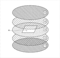
- FIG. 1 is a schematic diagram for explaining the raw film preparation process in Example 1.
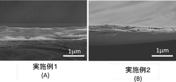
- FIG. FIG. 2 is scanning electron microscope (SEM) observation photographs of cross sections of the UHMW-PE submicron thin films obtained in Examples 1 and 2.
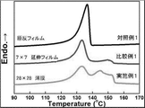
- FIG. 3 is a graph showing the melting profiles when the films or thin films obtained in Example 1, Comparative Example 1 and Control Example 1 were measured with a differential scanning calorimeter (DSC).
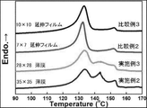
- FIG. 4 is a graph showing the melting profile when the films or thin films obtained in Examples 2-3 and Comparative Examples 2-3 were measured with a differential scanning calorimeter (DSC).
- FIG. 5 is scanning electron microscope (SEM) observation photographs of the film surfaces of the films or thin films obtained in Examples 1 and 2, Comparative Examples 1 and 3, and Control Example 1.
- FIG. FIG. 6 is a schematic diagram showing a method of adhesion test of the films or thin films obtained in Examples 1-2, Comparative Examples 1-3 and Control Example 1.
- a numerical range described using “to” represents a numerical range including the numerical values before and after “to” as lower and upper limits.
- the term “process” includes not only independent processes but also processes that cannot be clearly distinguished from other processes as long as the intended purpose of the process is achieved.
- the amount of each component in the composition refers to the total amount of the multiple substances present in the composition when there are multiple substances corresponding to each component in the composition, unless otherwise specified. means
- substituteduent is used in the sense of including unsubstituted ones and those having further substituents.
- alkyl group an unsubstituted alkyl group and an alkyl group further having a substituent.
- substituents for example, when the term "alkyl group” is used, an unsubstituted alkyl group and an alkyl group further having a substituent. The same applies to other substituents.
- the upper limit or lower limit described in a certain numerical range may be replaced with the upper limit or lower limit of the numerical range described in other steps. .
- the upper limit value or lower limit value described in a certain numerical range may be replaced with the values shown in the examples.
- a combination of two or more preferred aspects is a more preferred aspect.
- Room temperature as used herein means 20°C.
- the ultra-high molecular weight polyethylene submicron thin film of the present disclosure and its manufacturing method (hereinafter, the ultra-high molecular weight polyethylene submicron thin film of the present disclosure is also referred to as "UHMW-PE thin film” or “thin film”) will be described in detail. do.
- the "submicron thin film” in the present disclosure refers to a thin film having a thickness of 1 ⁇ m or less, and is sometimes simply called a “thin film” or an “ultra-thin film” in general.
- the thin film of the present disclosure contains ultra-high molecular weight polyethylene (UHMW-PE) with a viscosity average molecular weight of 1 million to 15 million as a main component, and has a film thickness of less than 1 ⁇ m and a tensile strength at break of 100 MPa or more.
- UHMW-PE ultra-high molecular weight polyethylene
- UHMW-PE-containing components that make up the thin film of the present disclosure are described in detail in the method of manufacturing the thin film of the present disclosure.
- the expression “contains UHMW-PE as a main component” indicates that the content of UHMW-PE is the largest among the components contained in the thin film.
- “contains UHMW-PE as a main component” means that the thin film contains 50% by mass, 60% by mass or more, 70% by mass or more, 80% by mass or more, or 90% by mass or more of UHMW-PE. indicates that it contains
- the film thickness of the thin film of the present disclosure is 1 ⁇ m or less, preferably 900 nm or less, more preferably 850 nm or less, and even more preferably 500 nm or less.
- the thickness of the thin film of the present disclosure is measured by the method shown in Examples described later.
- the diffuse light transmittance of the thin film of the present disclosure in the visible light region is preferably 50% or less, more preferably 40% or less, and even more preferably 30% or less.
- the parallel light transmittance of the thin film of the present disclosure in the visible light region is preferably 40% or more, more preferably 50% or more, and even more preferably 60% or more.
- the extended haze value of the thin film of the present disclosure in the visible light region is preferably 50% or less, more preferably 40% or less, and even more preferably 30% or less.
- the diffuse light transmittance, parallel light transmittance, and haze value in the visible light region of the thin film of the present disclosure are values (%) in the wavelength range of 360 to 750 nm, and are measured by the methods described later in Examples. be.
- the tensile strength at break of the thin film of the present disclosure is 100 MPa or more, preferably 150 MPa or more, more preferably 300 MPa or more.
- the tensile strength at break of the thin film of the present disclosure is measured by the method shown in Examples described later.
- the tear strength of the thin film of the present disclosure is preferably 1 N/mm or more, more preferably 5 N/mm or more, and even more preferably 10 N/mm or more. Note that the tear strength of the thin film of the present disclosure is measured by the method shown in Examples described later.
- the nitrogen permeability coefficient of the thin film of the present disclosure is preferably 1 ⁇ 10 ⁇ 14 mol ⁇ m/(m 2 ⁇ s ⁇ Pa) or less, and 5 ⁇ 10 ⁇ 15 mol ⁇ m/(m 2 ⁇ s ⁇ Pa) or less. More preferably, it is 1 ⁇ 10 ⁇ 15 mol ⁇ m/(m 2 ⁇ s ⁇ Pa) or less.
- the nitrogen permeability coefficient of the thin film of the present disclosure is measured by the method shown in Examples described later.
- the thin film of the present disclosure has a melting profile recorded with a differential scanning calorimeter that is (1) 130° C. or higher and lower than 140° C., (2) 140° C. or higher and lower than 150° C., and (3) 150° C. or higher. It preferably has one or more endothermic peaks.
- a differential scanning calorimeter that is (1) 130° C. or higher and lower than 140° C., (2) 140° C. or higher and lower than 150° C., and (3) 150° C. or higher. It preferably has one or more endothermic peaks.
- the melting profile recorded by the differential scanning calorimeter is the melting profile obtained by the "DSC heating measurement in this specification" described later.
- the adhesion coefficient in the peritoneal adhesion test of the present disclosure is preferably 1000 N/m or more, more preferably 2000 N/m or more, and even more preferably 3000 N/m or more.
- the thin film of the present disclosure When the thin film of the present disclosure is brought into close contact with a mating member, the thin film reflects its thinness and follows the shape of the mating member, thereby exhibiting excellent adhesion.
- the adhesion coefficient in the thin film adhesion test of the present disclosure is measured by the following method.
- a value (N/m) obtained by dividing the recorded maximum load by the thickness of the target film is obtained as an index of the adhesion of the target film (that is, the adhesion coefficient).
- the thin film manufacturing method of the present disclosure includes a first melt biaxial stretching step, a cooling step, and a second melt biaxial stretching step to obtain a UHMW-PE submicron thin film with a thickness of less than 1 ⁇ m.
- the method for producing a thin film of the present disclosure may use a commercially available raw film, but may also have a raw film preparation step.
- the method for producing a thin film of the present disclosure may have a melt biaxial contraction step between the first melt biaxial stretching step and the cooling step.
- the “melt biaxial stretching” is a method of stretching an original film or a stretched film along the x-axis direction and the y-axis direction at a temperature higher than its melting point. Each step will be described below.
- ultra-high molecular weight polyethylene (UHMW-PE) raw material powder having a viscosity average molecular weight of 1,000,000 to 15,000,000 is formed into a film at a temperature equal to or higher than the melting point of the ultra-high molecular weight polyethylene raw material powder. Thereby, a raw film made of ultra-high molecular weight polyethylene is obtained.
- UHMW-PE ultra-high molecular weight polyethylene
- the UHMW-PE raw material powder is a powdery polyethylene raw material powder having a viscosity average molecular weight (Mv) of 1 million to 15 million, more preferably a polyethylene raw material powder having a Mv of 1 million to 10 million, and polyethylene having a Mv of 1.2 million to 6 million.
- a raw material powder is more preferred. That is, the Mv of UHMW-PE contained in the thin film of the present disclosure is preferably within the above range.
- the viscosity average molecular weight is a value measured in a decalin solvent (135° C.), and the intrinsic viscosity ([ ⁇ ]) is preferably 7 dl/g to 45 dl/g, more preferably 7 dl/g to 35 dl/g.
- the molecular weight of UHMW-PE is measured as described above, but when it is difficult to dissolve in decalin solvent, the molecular weight of UHMW-PE is measured by the following method.
- This method is an application of the ASTM D 1430-65T method.
- a UHMW-PE raw material powder whose molecular weight is to be measured is formed into a film by melt press molding to prepare a dumbbell-shaped test piece specified in the ASTM D 1430-65T method.
- a plurality of dumbbell-shaped specimens thus obtained are prepared, different loads are applied to each specimen, and the specimens are immersed in a glycol bath heated to 150°C.
- the load applied causes the specimen to elongate
- the time required to cause 600% elongation is measured.
- the time required for elongation obtained above is plotted against the tensile stress (load divided by the cross-sectional area of the specimen) applied to the specimen on a logarithmic coordinate axis.
- the plotted values show linearity, and from this graph, the stress (N/mm 2 ) called the yield value required for an elongation time of 10 minutes can be obtained.
- the yield value in UHMW-PE is preferably in the range of 0.05 N/mm 2 to 1.5 N/mm 2 .
- the viscosity average molecular weight measured by the viscosity method correlates with the yield value, so the yield value measurement method can detect the molecular weight.
- the particle size of the UHMW-PE raw material powder is preferably 2000 ⁇ m or less, more preferably 1 ⁇ m to 2000 ⁇ m, and still more preferably 10 ⁇ m to 1000 ⁇ m in terms of volume average particle size (D 50 ).
- UHMW-PE may be a polymer polymerized using a known catalyst, but powdery polyethylene polymerized using a Ziegler catalyst or metallocene catalyst is preferably used.
- Mw and Mn are weight-average molecular weight and number-average molecular weight, respectively, and can be determined by GPC measurement.
- UHMW-PE preferably has only ethylene as a structural unit because it has a high degree of crystallinity and excellent physical properties such as strength. However, it may be a polymer or copolymer containing structural units derived from ethylene.
- structural units constituting the copolymer together with ethylene structural units include propylene, 1-butene, 1-hexene, 1-octene, and 4-methyl-1-pentene.
- Alpha-olefins and their derivatives may be mentioned. That is, the name of UHMW-PE in this specification also includes copolymers of ethylene and ⁇ -olefins. Therefore, UHMW-PE also includes polyethylene containing long chain branches such as linear low density polyethylene and low density polyethylene.
- the UHMW-PE raw material powder may be used in combination with other ingredients other than UHMW-PE as long as the effect is not impaired. That is, the thin films of the present disclosure may contain other components than UHMW-PE.
- Components other than UHMW-PE include, for example, polymers such as polyethylene having a lower molecular weight than UHMW-PE; known additives such as plasticizers, antioxidants, weathering agents, light stabilizers, ultraviolet absorbers, Heat stabilizers, lubricants, release agents, antistatic agents, flame retardants, foaming agents, fillers such as silica, antibacterial agents, antifungal agents, nucleating agents, coloring agents such as pigments, etc., are added to ordinary polyolefins. ingredients.
- One or two or more of the above-described other components may be included in the UHMW-PE raw material powder depending on the purpose within a range that does not impair the effect.
- antioxidants include phenolic antioxidants such as Irganox 1076 (trade name) manufactured by BASF; An antioxidant or the like is preferably used.
- phenolic antioxidants such as Irganox 1076 (trade name) manufactured by BASF; An antioxidant or the like is preferably used.
- the other components are dispersed or dissolved in another solvent and then mixed into the raw material powder. known addition methods, such as a method in which only the solvent is removed by volatilization, and a method in which the ingredients are kneaded in a melted state of the ultra-high molecular weight polyethylene raw material.
- the UHMW-PE raw material powder described above is formed into a film at a temperature equal to or higher than the melting point of the UHMW-PE raw material powder to obtain a raw film.
- a raw film having improved fusion between the UHMW-PE raw material powders can be obtained.
- the film forming temperature is preferably 130°C to 250°C, more preferably 150°C to 200°C.
- melting point refers to the endothermic peak temperature (°C) of a melting profile obtained by temperature elevation measurement with a differential scanning calorimeter (DSC).
- the melting point of the UHMW-PE raw material powder is in the range of about 135° C. to 145° C., although it varies depending on the manufacturing method and molecular weight of the UHMW-PE raw material.
- the temperature of the peak with the highest intensity is taken as the melting point.
- the DSC temperature elevation measurement in this specification is performed by raising the temperature to a temperature range of 30 ° C. to 180 ° C.
- Film-like molding is preferably press molding. Further, press molding is more preferably performed under reduced pressure.
- the press pressure in press molding is preferably 0.01 MPa to 100 MPa, more preferably 0.1 MPa to 50 MPa.
- the reduced pressure in press molding is preferably 10 Torr or less, more preferably 1 Torr or less. Press molding under reduced pressure improves the adhesion between the UHMW-PE raw material powders and integrates them. Therefore, a thin film made of UHMW-PE can be obtained in which the properties of UHMW-PE are fully exhibited.
- roll molding may be sufficient as film-form molding.
- roll molding for example, "first roll treatment step” and “second roll treatment step” in the method for producing a polyethylene film described in JP-A-2019-193997 can be exemplified.
- press molding and roll molding may be combined for forming the film.
- the thickness of the raw film obtained in the raw film preparation process is preferably 1000 ⁇ m or less, more preferably 300 ⁇ m or less, and even more preferably 100 ⁇ m or less.
- First melt biaxial stretching step In the first melt biaxial stretching step, a raw film (or a raw film formed in the raw film preparation step) containing ultra-high molecular weight polyethylene having a viscosity average molecular weight of 1 million to 15 million as a main component is stretched. The film is melt biaxially stretched along the x-axis and y-axis at a temperature equal to or higher than the melting point of the original film.
- the first melt biaxial stretching may be sequential biaxial stretching in which stretching is performed in the x-axis direction and then in the y-axis direction perpendicular to the x-axis direction, or y Simultaneous biaxial stretching in which the film is stretched simultaneously in the axial direction may also be used.
- the time difference is, for example, 0.1 to 100 minutes.
- the drawing speed in the x-axis direction and the drawing speed in the y-axis direction may be the same or different.
- the speed difference is, for example, 0.1 to 1000 mm/min.
- the first melt biaxial stretching temperature is set to the melting point of the original film or higher. By stretching the raw film at a temperature equal to or higher than the melting point of the raw film, it is possible to stretch the raw film up to a high magnification ratio, which is advantageous for thinning and increasing strength.
- the first melt biaxial stretching temperature is preferably 120°C to 180°C, more preferably 130°C to 180°C, still more preferably 136°C to 180°C, and most preferably 136°C to 170°C. The temperature may be varied during the first melt biaxial stretching within this temperature range.
- the temperature conditions in the first melt biaxial stretching may be appropriately selected according to the viscosity-average molecular weight (Mv) of the UHMW-PE raw material powder, which is the raw material of the raw film, and the copolymer composition.
- Mv viscosity-average molecular weight
- the temperature is preferably around 136°C to 145°C near the melting point. Biaxial stretching processing in is possible.
- the stretching ratio in the first melt biaxial stretching is preferably 2 times or more, more preferably 5 times or more, the length of the original film in both the x-axis direction and the y-axis direction.
- the draw ratios in the x-axis direction and the y-axis direction may be the same or different.
- the stretching speed in the first melt biaxial stretching is preferably in the range of 1 mm/min to 1000 mm/min, more preferably in the range of 10 mm/min to 500 mm/min.
- the first melt biaxial stretching is carried out at a stretching rate of less than 1 mm/min, the film in the molten state bends and hangs downward, making it impossible to obtain a thin and high-strength film.
- a holding step of holding the film at the temperature for the first melt biaxial stretching for a certain period of time may be included.
- the time for which the temperature is maintained is preferably 1 minute to 180 minutes, more preferably 1 minute to 10 minutes.
- the biaxial stretching machine is preferably a biaxial stretching machine equipped with a stress detection mechanism so that it can be confirmed that the biaxial stretching is being carried out in a molten state.
- the film thickness of the chuck portion (end portion) gradually decreases as the film is stretched, it becomes more slippery. is preferred.
- the thickness of the stretched film obtained in the first melt biaxial stretching step is preferably 500 ⁇ m or less, more preferably 150 ⁇ m or less, and more preferably 50 ⁇ m or less from the viewpoint of obtaining a UHMW-PE thin film having a thickness of less than 1 ⁇ m.
- melt biaxial contraction process In the melt biaxial shrinking step, before the cooling step, the stretched film obtained in the first melt biaxial stretching step (hereinafter also referred to as "first stretched film”) is stretched at a temperature equal to or higher than the melting point of the stretched film in the x-axis direction. Melt biaxial shrinkage along the direction and the y-axis. Note that the melt biaxial contraction step is a step that is optionally performed.
- the melting biaxial shrinkage may be sequential biaxial shrinkage in which shrinkage occurs in the x-axis direction and then shrinks in the y-axis direction perpendicular to the x-axis direction, or in the y-axis direction perpendicular to the x-axis direction and the x-axis direction. Simultaneous biaxial shrinkage may also be used.
- Melt biaxial shrinkage may be performed immediately after performing the first melt biaxial stretching, or after performing the first melt biaxial stretching, the temperature for performing melt biaxial shrinkage is maintained for a certain period of time (e.g., 1 to 10 minutes) may be carried out after holding.
- a certain period of time e.g. 1 to 10 minutes
- the temperature of the melt biaxial shrinkage is preferably 80°C to 180°C, more preferably 120°C to 165°C, still more preferably 136°C to 165°C, and particularly preferably 140°C to 155°C. It should be noted that the temperature may be varied during the melting biaxial shrinkage within this temperature range.
- the shrinkage ratio of the melt biaxial shrinkage is that the length after shrinkage is 5% of the length before shrinkage (the length of the first stretched film immediately after the first melt biaxial stretching) in both the x-axis direction and the y-axis direction. ⁇ 95% is preferred, and 20% to 75% is more preferred.
- the shrinkage ratios in the x-axis direction and the y-axis direction may be the same or different.
- the first stretched film stretched in the first melt biaxial stretching step (or the first stretched film shrunk in the melt biaxial shrinking step) is cooled below the melting point of the first stretched film.
- the first stretched film is cooled, for example, at a cooling rate of 1° C./min to 1000° C./min to above room temperature and below the melting point of the first stretched film.
- melt biaxial stretching step In the second melt biaxial stretching step, the first stretched film cooled in the cooling step is again melt biaxially stretched along the x-axis direction and the y-axis direction at a temperature equal to or higher than the melting point of the first stretched film.
- the second melt biaxial stretching may be sequential biaxial stretching in which stretching is performed in the x-axis direction and then in the y-axis direction perpendicular to the x-axis direction, or y Simultaneous biaxial stretching in which the film is stretched simultaneously in the axial direction may also be used.
- the time difference is, for example, 0.1 to 100 minutes.
- the drawing speed in the x-axis direction and the drawing speed in the y-axis direction may be the same or different.
- the speed difference is, for example, 0.1 to 1000 mm/min.
- the temperature of the second melt biaxial stretching should be equal to or higher than the melting point of the first stretched film.
- the second melt biaxial stretching temperature is preferably 120°C to 180°C, more preferably 130°C to 180°C, still more preferably 136°C to 180°C, and most preferably 136°C to 170°C.
- the temperature may be changed during the second melt biaxial stretching within this temperature range.
- the temperature conditions in the first melt biaxial stretching may be appropriately selected according to the viscosity-average molecular weight (Mv) of the UHMW-PE raw material powder, which is the raw material of the raw film, and the copolymer composition.
- Mv viscosity-average molecular weight
- the temperature is preferably around 136°C to 145°C near the melting point. Biaxial stretching processing in is possible.
- the stretching ratio in the second melt biaxial stretching is preferably 5 times or more, more preferably 10 times or more, and even more preferably 20 times or more, the length of the original film in both the x-axis direction and the y-axis direction.
- the draw ratios in the x-axis direction and the y-axis direction may be the same or different.
- the ratio of the draw ratio in the first melt biaxial stretching and the draw ratio in the second melt biaxial stretching is the x-axis It is preferably 1.1 times to 20 times, more preferably 2 times to 10 times, both in the direction and the y-axis direction.
- the stretching speed in the second melt biaxial stretching is preferably in the range of 1 mm/min to 1000 mm/min, more preferably in the range of 10 mm/min to 500 mm/min. If the second melt biaxial stretching is performed at a drawing speed of less than 1 mm/min, the film in the molten state will bend and droop downward, making it impossible to obtain a thin and high-strength film.
- a holding step of holding the film at the temperature for the first melt biaxial stretching for a certain period of time may be included.
- the time for which the temperature is maintained is preferably 1 minute to 180 minutes, more preferably 1 minute to 10 minutes.
- a hot air blowing type biaxial stretching machine or the like is used to melt only the central portion of the first stretched film, and the chuck portion (end portion). It is preferable to perform the stretching in a state in which the film is not melted.
- the biaxial stretching machine is preferably a biaxial stretching machine equipped with a stress detection mechanism so that it can be confirmed that the biaxial stretching is being carried out in a molten state.
- the film thickness of the chuck portion (end portion) gradually decreases as the film is stretched, it becomes more slippery. is preferred.
- the second melt biaxial stretching is carried out until the thickness of the obtained second stretched film is less than 1 ⁇ m. After the second melt biaxial stretching, for example, the obtained second stretched film is cooled to room temperature.
- a heat treatment may be performed after the second melt biaxial stretching or after cooling.
- the heat treatment temperature is preferably 100°C to 180°C, more preferably 120°C to 160°C. Note that the temperature may be changed during the heat treatment as long as it is within this temperature range. At this time, the heat treatment time is preferably 1 minute to 180 minutes, more preferably 1 minute to 10 minutes.
- a UHMW-PE thin film having a thickness of less than 1 ⁇ m is obtained through the steps described above.
- the stretched film is cooled to a temperature below the melting point of the stretched film, and again at a temperature above the melting point of the stretched film in the x-axis direction and the y-axis direction.
- the melt biaxial stretching cooling step of cooling below the melting point of the stretched film and after the second melt biaxial stretching step, the stretched film is stretched at a temperature above the melting point of the stretched film.
- a third step including at least one melt-shrinking, stretching and cooling step of cooling to the melting point of the stretched film or less may be provided, and the third step may be repeated once or multiple times.
- post-treatment may be performed on the obtained UHMW-PE thin film.
- the post-treatment include a treatment for cross-linking the UHMW-PE by subjecting the UHMW-PE thin film to electron beam irradiation or radiation irradiation.
- the post-treatment can further improve the chemical resistance, dimensional stability, heat resistance, etc. of the UHMW-PE thin film.
- a UHMW-PE raw film was molded as follows (raw film preparation step). As shown in FIG. 1, a polyimide film (2) for release with a thickness of 125 ⁇ m is placed on a disk-shaped stainless steel plate (1) with a diameter of 150 mm ⁇ and a thickness of 2 mm. A 100 mm ⁇ 100 mm rectangular window (indicated as region A in FIG. 1) was cut out (3) in a disk-shaped stainless steel plate, and powdered UHMW-PE raw material (Hizex Million 340M manufactured by Mitsui Chemicals) was placed in the rectangular window A. , viscosity-average molecular weight of 3,300,000, and average particle diameter of 150 ⁇ m) was placed. A release polyimide film (4) having a thickness of 125 ⁇ m was placed thereon, and a film (5) having a diameter of 150 mm ⁇ and a thickness of 2 mm was further placed thereon.
- UHMW-PE raw film was molded as follows (raw film preparation step). As shown in FIG
- the whole was placed between the upper and lower press plates in a press (manufactured by Baldwin Co., Ltd.) installed in a vacuum chamber at room temperature (25° C.), and after depressurizing to 1 ⁇ 10 ⁇ 1 Torr with a rotary pump, the upper and lower The gap between the press plates was brought as close as possible so as not to apply stress, heated to 200° C., maintained at 200° C. for 5 minutes, and then pressed at a pressure of 4.5 MPa (cylinder pressure 60 MPa). The power to the heater was turned off, and the mixture was gradually cooled to room temperature (25°C) under reduced pressure. After that, the vacuum chamber was opened and the raw UHMW-PE film was taken out. The film thickness of the obtained UHMW-PE raw film was about 0.30 mm.
- the resulting UHMW-PE raw film was cut into an initial length of 65 mm ⁇ 65 mm, set in a large biaxial stretching machine described in WO2018/088280 equipped with an air chuck function and a stress detector, and blown with hot air. and heated. After holding at 155° C. for 5 minutes, simultaneous biaxial stretching was carried out along the x-axis direction and the y-axis direction at a stretching temperature of 155° C. and a stretching speed of 180 mm/min (first melt biaxial stretching step). The draw ratio was 7 times ⁇ 7 times. This was cooled to room temperature and taken out from the large biaxial stretching machine (cooling step).
- the obtained first stretched film was cut into an initial length of 35 mm ⁇ 35 mm, set in a plane expansion stretching machine (manufactured by Island Industry Co., Ltd.) equipped with an air chuck function and a stress detector, and heated by blowing hot air. After holding at 155° C. for 5 minutes, simultaneous biaxial stretching was carried out along the x-axis direction and the y-axis direction at a stretching temperature of 155° C. and a stretching speed of 20 mm/min (second melt biaxial stretching step). The draw ratio was set to 4 ⁇ 4. Therefore, the total draw ratio based on the raw film (press-molded UHMW-PE raw film) was 28 ⁇ 28.
- the thickness of the thin film made of UHMW-PE is the average value of the thicknesses at five locations observed by SEM of the cross section.
- the obtained UHMW-PE thin film had a tensile strength at break of 201 MPa, a tear strength of 14.5 N/mm, and a nitrogen permeability coefficient of 1.48 ⁇ 10 ⁇ 16 mol ⁇ m/(m 2 ⁇ s ⁇ Pa). there were.
- the total light transmittance was 88.6%
- the diffuse light transmittance was 32.2%
- the parallel light transmittance was 56.3%
- the haze value was 36.4%.
- an adhesion coefficient of 3660 N/m was obtained.
- Example 2 A UHMW-PE raw film was molded in the same manner as in Example 1 (raw film preparation step).
- the draw ratio in the first melt biaxial stretching step was 10 times ⁇ 10 times, and while the temperature was maintained at 155°C, the shrinkage rate was 180 mm/min, and the draw ratio was 7 times ⁇ 7 along the x-axis direction and the y-axis direction.
- Simultaneous biaxial contraction was performed up to 100% (melt contraction step). It was cooled to room temperature in the same manner as in Example 1 and taken out from the large biaxial stretching machine (cooling step).
- the draw ratio in the second melt biaxial drawing step was 5 ⁇ 5. Therefore, the total draw ratio was 35 ⁇ 35.
- the obtained UHMW-PE thin film had a tensile breaking strength of 304 MPa, a tearing strength of 36.7 N/mm, and a nitrogen permeability coefficient of 2.63 ⁇ 10 ⁇ 15 mol ⁇ m/(m 2 ⁇ s ⁇ Pa). there were. Furthermore, in the visible light region, the total light transmittance was 88.6%, the diffuse light transmittance was 25.4%, the parallel light transmittance was 63.1%, and the haze value was 28.7%. Furthermore, when the obtained thin film made of UHMW-PE was subjected to an adhesion test using an aluminum plate as a counterpart material, an adhesion coefficient of 4810 N/m was obtained.
- Example 3 A UHMW-PE thin film was prepared in the same manner as in Example 2, except that the draw ratio in the second melt biaxial drawing step was 4 ⁇ 4. Therefore, the total draw ratio was 28 ⁇ 28. A cross-section of the obtained UHMW-PE thin film was observed by SEM, and the film thickness was 841 nm. The obtained UHMW-PE thin film had a tensile strength at break of 156 MPa, a tear strength of 15.2 N/mm, and a nitrogen permeability coefficient of 6.10 ⁇ 10 ⁇ 18 mol ⁇ m/(m 2 ⁇ s ⁇ Pa). there were.
- the total light transmittance was 88.6%
- the diffuse light transmittance was 31.0%
- the parallel light transmittance was 57.6%
- the haze value was 35.0%.
- an adhesion coefficient of 3340 N/m was obtained.
- Example 1 A UHMW-PE film was molded in the same manner as in Example 1 (original film preparation step). The stretching ratio in the first melt biaxial stretching step was set to 7 ⁇ 7 times, the film was cooled to room temperature in the same manner as in Example 1, and taken out from the large-sized biaxial stretching machine (cooling step). When the film thickness of the obtained UHMW-PE stretched film was measured with a micrometer, it was 23 ⁇ m. The tensile breaking strength of the obtained stretched UHMW-PE film was 65.1 MPa, the tearing strength was 12.3 N/mm, and the nitrogen permeability coefficient was 1.56 ⁇ 10 ⁇ 16 mol ⁇ m/(m 2 ⁇ s ⁇ Pa).
- the total light transmittance was 93.6%
- the diffuse light transmittance was 78.5%
- the parallel light transmittance was 15.1%
- the haze value was 83.9%.
- an adhesion test was conducted on the obtained stretched film made of UHMW-PE using an aluminum plate as a counterpart material, an adhesion coefficient of 165 N/m was obtained.
- Example 2 A UHMW-PE raw film was molded in the same manner as in Example 1 (raw film preparation step).
- the stretching ratio in the first melt biaxial stretching step was 10 times ⁇ 10 times, and simultaneous biaxial contraction was performed up to a stretching ratio of 7 times ⁇ 7 times while maintaining the temperature at 155 ° C. in the same manner as in Example 2 (shrinkage step ), cooled to room temperature, and taken out from the biaxial stretching machine (cooling step).
- the film thickness of the obtained stretched UHMW-PE film was measured with a micrometer and found to be 26 ⁇ m.
- the obtained UHMW-PE stretched film had a tensile strength at break of 36.8 MPa, a tear strength of 9.9 N/mm, and a nitrogen permeability coefficient of 1.39 ⁇ 10 ⁇ 16 mol ⁇ m/(m 2 ⁇ s ⁇ Pa). Furthermore, in the visible light region, the total light transmittance was 96.5%, the diffuse light transmittance was 87.8%, the parallel light transmittance was 8.7%, and the haze value was 90.4%. Furthermore, when an adhesion test was conducted on the obtained stretched film made of UHMW-PE using an aluminum plate as a counterpart material, an adhesion coefficient of 667 N/m was obtained.
- a UHMW-PE stretched film was prepared in the same manner as in Comparative Example 1, except that the stretching ratio in the first melt biaxial stretching step was 10 ⁇ 10.
- the thickness of the obtained stretched UHMW-PE film was measured with a micrometer and found to be 15 ⁇ m.
- the tensile breaking strength of the obtained UHMW-PE stretched film was 93 MPa, and the tearing strength was 14.1 N/cm.
- the maximum draw ratio in the large-sized biaxial stretching machine described in WO2018/088280 is 20 times ⁇ 20 times, and the first melt biaxial stretching step and the second melt biaxial stretching step are continuously performed. Therefore, in order to achieve a film thickness of less than 1 ⁇ m, it is necessary to thin the UHMW-PE raw film. Therefore, by setting the thickness of the disk-shaped stainless steel plate in which the rectangular window was cut out in FIG. As in Example 1, this was set in the large biaxial stretching machine described above, held at 155 ° C. for 5 minutes, and stretched at a stretching temperature of 155 ° C. and a stretching speed of 180 mm / min along the x-axis direction and the y-axis direction.
- first melt biaxial stretching step Simultaneous biaxial stretching was performed (first melt biaxial stretching step).
- the draw ratio was set to 6 ⁇ 6. After that, it was held at 155° C. for 5 minutes without being removed from the large-sized biaxial stretching machine, and then simultaneously biaxially stretched along the x-axis direction and the y-axis direction at a stretching temperature of 155° C. and a stretching speed of 20 mm/min (second 2 melt biaxial stretching process).
- second 2 melt biaxial stretching process the film broke before reaching a total draw ratio of 11 ⁇ 11, and a UHMW-PE thin film could not be obtained.
- Example Y In the same manner as in Example Y, the film was held at 155° C. for 5 minutes without being removed from the large biaxial stretching machine, and then simultaneously biaxially stretched along the x-axis direction and the y-axis direction at a stretching temperature of 155° C. and a stretching speed of 20 mm/min. (second melt biaxial stretching step). However, the film broke before reaching a total draw ratio of 11 ⁇ 11, and a UHMW-PE thin film could not be obtained.
- Example 1 A UHMW-PE raw film was molded in the same manner as in Example 1 (raw film preparation step). When the film thickness of the obtained UHMW-PE raw film was measured with a micrometer, it was 351 ⁇ m.
- the obtained UHMW-PE raw film had a tensile strength at break of 33.5 MPa, a tear strength of 32.2 N/cm, and a nitrogen permeability coefficient of 2.83 ⁇ 10 ⁇ 15 mol ⁇ m/(m 2 ⁇ s ⁇ Pa). Furthermore, in the visible light region, the total light transmittance was 80.9%, the diffuse light transmittance was 65.9%, the parallel light transmittance was 15.0%, and the haze value was 81.5%. Furthermore, when the obtained UHMW-PE raw film was subjected to an adhesion test using an aluminum plate as a counterpart material, an adhesion coefficient of 6.68 N/m was obtained.
- the tensile strength at break of the UHMW-PE thin films of Examples 1 to 3 was less than 1 ⁇ m compared to the UHMW-PE films of Comparative Examples 1 to 3 and Control 1. Although it was a thin film, it had a high strength of 100 MPa or more.
- the tear strength of the UHMW-PE thin films of Examples 1 to 3 was less than 1 ⁇ m compared to the UHMW-PE films of Comparative Examples 1 to 3 and Control 1. Despite this, the strength was as high as 10 N/mm or more.
- DSC Differential Scanning Calorimeter
- FIG. 3 shows the original film (Comparative Example 1), the UHMW-PE stretched film (Comparative Example 1) obtained by subjecting the original film to first melt biaxial stretching to 7 times ⁇ 7 times, and the UHMW subjected to the first melt biaxial stretching.
- - Shows the DSC melting curve of the UHMW-PE thin film (Example 1) obtained by subjecting the stretched PE film to 4 times ⁇ 4 times (total stretching ratio is 28 times ⁇ 28 times) by second melt biaxial stretching.
- the original film Control Example 1
- the stretched film (Comparative Example 1) subjected to the first melt biaxial stretching a peak derived from extended chain crystals (ECC) was observed around 153°C.
- ECC extended chain crystals
- the UHMW-PE thin film (Example 1) obtained by subjecting this stretched film to the second melt biaxial stretching the ECC-derived peak increased, and a new endothermic peak appeared at around 143°C, which is the intermediate position between these peaks. ing.
- the UHMW-PE thin film of Example 1 subjected to the second melt biaxial stretching has the following characteristics in the melting profile recorded by the differential scanning calorimeter: (1) 130 ° C. or higher and lower than 140 ° C.; It can be seen that there are one or more endothermic peaks below 150°C and (3) above 150°C, respectively.
- a UHMW-PE stretched film (Comparative Example 3) obtained by first melting biaxially stretching up to 10 times ⁇ 10 times the original film (Reference Example 1), and stretching the first melt biaxially stretching up to 10 times ⁇ 10 times.
- the UHMW-PE stretched film (Comparative Example 2) melt-shrunk to 7 times ⁇ 7 times, and the melt-shrunk UHMW-PE stretched film (Comparative Example 2) were further stretched 4 times ⁇ 4 times ( A UHMW-PE thin film (Example 3) that was subjected to second melt biaxial stretching until the total draw ratio was 28 times ⁇ 28 times), and a UHMW-PE stretched film (Comparative Example 2) that was similarly melt-shrunk. Further, the DSC melting curve of the UHMW-PE thin film (Example 2) subjected to the second melting biaxial stretching up to 5 times ⁇ 5 times (total stretching ratio of 35 times ⁇ 35 times) is shown.
- the UHMW-PE thin films of Examples 2 and 3 also had a melting profile recorded with a differential scanning calorimeter, (1) 130 ° C. or higher and lower than 140 ° C., (2) 140 ° C. or higher and lower than 150 ° C., and ( 3) It can be seen that they each have one or more endothermic peaks at 150°C or higher.
- Haze value measurements were performed to evaluate the permeability. Haze value measurement is performed using a HZ-2 type haze meter manufactured by Suga Test Instruments Co., Ltd., in accordance with JIS K 7361: (1997). Transmittance (%), diffuse light transmittance (%), parallel light transmittance (%) and haze value (%) were measured.
- the UHMW-PE thin films of Examples 1 to 3 had a total light transmittance of 80% or more, a diffuse light transmittance of 40% or less, and a parallel light transmittance of The haze value was 40% or more and 40% or less, indicating high transparency.
- Nitrogen Permeability Coefficient In order to evaluate the barrier properties of the UHMW-PE films or thin films of Examples 1 to 3, Comparative Examples 1 to 3 and Control Example 1, model K-315N-01 manufactured by Tsukubarika Seiki was used. Nitrogen permeation coefficient was measured at room temperature using a membrane diffusion measurement apparatus. Nitrogen is used as the permeation gas, and a data logger GL20 made by Graphtec is connected to the permeation device. The nitrogen permeability coefficient ⁇ was determined by (2). The sample piece was cut into a circle with a diameter of 30 mm.
- an area of 1 cm ⁇ 3 cm at the tip of the target film or thin strip and an area of 1 cm ⁇ 3 cm at the tip of the strip of aluminum plate as the mating material can be brought into close contact with each other.
- a tensilon universal testing machine RTC-1325A manufactured by ORIENTEC was used, and the ends of both strips opposite to the contact portion were fixed to upper and lower chuck portions, respectively, and the test speed was 5 mm/min. and pulled vertically at room temperature.
- the value (N/m) obtained by dividing the maximum load in the stress chart recorded at this time by the film thickness of the target film or thin film was used as an index of adhesion (that is, adhesion coefficient).
- 10 is a target film or thin film
- 11 is an aluminum plate
- 12 is liquid paraffin.
- the nitrogen permeability coefficients of the UHMW-PE thin films of Examples 1 to 3 were less than 1 ⁇ m compared to the UHMW-PE films of Comparative Examples 1 to 3 and Control Example 1. Although it was a thin film, it was the same level or less, showing excellent barrier properties.
- the UHMW-PE thin films of Examples 1 to 3 have a film thickness of less than 1 ⁇ m and a high tensile strength at break.
- the UHMW-PE thin films of Examples 1 to 3 also have high tensile strength at break and high tear strength.
- the nitrogen permeability coefficient is low and the barrier property is high.
- the total light transmittance is high, the diffuse light transmittance is low, the parallel light transmittance is high, and the haze value is low. Therefore, it has excellent transparency.
Abstract
Description
特許文献2:特開2019-193997号
特許文献3:国際公開WO2018/039436号 Patent Document 1: JP 2010-201649 Patent Document 2: JP 2019-193997 Patent Document 3: International Publication WO2018/039436
非特許文献2:S.Takeoka et al, Adv. Mater.,Vol.25, p.545 (2013)
非特許文献3:P.Smith et al, J.Mater.Sci.,Vol.15,p.505(1980)
非特許文献4:A.Pankaj et al, Chem.Rev.,Vol.104,p.4419(2004)
非特許文献5:H.Uehara et al.,Adv.Funct.Mater.,Vol.22,p.2048 (2012)
非特許文献6:Thomas Keller, Matthias Grosch, and Klaus D. Jand.Macromolecules 2007, 40, 5812-5819 Non-Patent Document 1: K.K. Tanaka et al. , ACS Macro Lett. , Vol. 7, p. 1198 (2018)
Non-Patent Document 2: S. Takeoka et al, Adv. Mater. , Vol. 25, p. 545 (2013)
Non-Patent Document 3: P.S. Smith et al,J. Mater. Sci. , Vol. 15, p. 505 (1980)
Non-Patent Document 4: A. Pankaj et al, Chem. Rev. , Vol. 104, p. 4419 (2004)
Non-Patent Document 5: H. Uehara et al. , Adv. Funct. Mater. , Vol. 22, p. 2048 (2012)
Non-Patent Document 6: Thomas Keller, Matthias Grosch, and Klaus D.; Jand. Macromolecules 2007, 40, 5812-5819
また、発明者らは、これら1段目の溶融二軸延伸後に溶融収縮処理を施した後に冷却した延伸フィルムを、さらに2段目の溶融二軸延伸を行った。
このように、発明者らは、上記多段延伸によって、UHMW-PE製サブミクロン薄膜の創製を目指した。 First, the inventors performed the first-stage melt biaxial stretching along the x-axis direction and the y-axis direction to a predetermined draw ratio, and then cooled the original film made of UHMW-PE. The stretched film thus obtained was further subjected to a second melt biaxial stretching.
The inventors further subjected the stretched film, which had been melt-shrinked after the first-stage melt-biaxial stretching and then cooled, to the second-stage melt-biaxial stretching.
Thus, the inventors aimed to create a UHMW-PE submicron thin film by the multi-stage stretching.
<1>
主成分として粘度平均分子量100万~1500万である超高分子量ポリエチレンを含み、膜厚が1μm未満かつ引張破断強度が100MPa以上である超高分子量ポリエチレン製サブミクロン薄膜。
<2>
引き裂き強度が5N/mm以上である<1>に記載の超高分子量ポリエチレン製サブミクロン薄膜。
<3>
窒素透過係数が1×10-14mol・m/(m2・s・Pa)以下である<1>又は<2>に記載の超高分子量ポリエチレン製サブミクロン薄膜。
<4>
可視光領域におけるヘーズ値が50%以下である<1>~<3>のいずれか1項に記載の超高分子量ポリエチレン製サブミクロン薄膜。
<5>
示差走査型熱量計で記録した融解プロファイルにおいて、(1)130℃以上140℃未満、(2)140℃以上150℃未満、および、(3)150℃以上に、それぞれ一つ以上の吸熱ピークを有する<1>~<4>のいずれか1項に記載の超高分子量ポリエチレン製サブミクロン薄膜。
<6>
密着性試験による密着性係数が1000N/m以上である請求項1~請求項5のいずれか1項に記載の超高分子量ポリエチレン製サブミクロン薄膜。
<7>
主成分として粘度平均分子量100万~1500万である超高分子量ポリエチレンを含む原反フィルムを、該原反フィルムの融点以上の温度でx軸方向およびy軸方向に沿って溶融二軸延伸する第1溶融二軸延伸工程と、
前記第1溶融二軸延伸工程で延伸された延伸フィルムを、該延伸フィルムの融点以下に冷却する冷却工程と、
前記冷却工程で冷却された延伸フィルムを、該延伸フィルムの融点以上の温度で再びx軸方向およびy軸方向に沿って溶融二軸延伸する第2溶融二軸延伸工程と、
を有し、
得られる超高分子量ポリエチレン製サブミクロン薄膜の膜厚が1μm未満である超高分子量ポリエチレン製サブミクロン薄膜の製造方法。
<8>
前記冷却工程前に、前記第1溶融二軸延伸工程で得られた延伸フィルムを、該延伸フィルムの融点以上の温度でx軸方向およびy軸方向に沿って溶融二軸収縮させる溶融二軸収縮工程を有する<6>に記載の超高分子量ポリエチレン製サブミクロン薄膜の製造方法。
<9>
前記第2溶融二軸延伸工程後、前記延伸フィルムを、該延伸フィルムの融点以下に冷却し、該延伸フィルムの融点以上の温度で再びx軸方向およびy軸方向に沿って溶融二軸延伸した後、該延伸フィルムの融点以下に冷却する溶融二軸延伸冷却工程、並びに、前記第2溶融二軸延伸工程後、前記延伸フィルムを、該延伸フィルムの融点以上の温度でx軸方向およびy軸方向に沿って溶融二軸収縮させ、該延伸フィルムの融点以下に冷却し、該延伸フィルムの融点以上の温度で再びx軸方向およびy軸方向に沿って溶融二軸延伸した後、該延伸フィルムの融点以下に冷却する溶融収縮延伸冷却工程を少なくとも一方含む第3工程を有し、
前記第3工程を、1回又は複数回繰り返す<7>又は<8>に記載の超高分子量ポリエチレン製サブミクロン薄膜の製造方法。
<10>
粘度平均分子量が100万~1500万である超高分子量ポリエチレン原料パウダーを、該超高分子量ポリエチレン原料パウダーの融点以上の温度でフィルム状に成形する原反フィルム調製工程を有する<7>~は<9>のいずれか1項に記載の超高分子量ポリエチレン製サブミクロン薄膜の製造方法。
<11>
前記原反フィルム調製工程が、プレス成形により、前記超高分子量ポリエチレン原料パウダーをフィルム状に成形する工程である<10>に記載の超高分子量ポリエチレン製サブミクロン薄膜の製造方法。
<12>
前記プレス成形が、減圧下で行われる<11>に記載の超高分子量ポリエチレン製サブミクロン薄膜の製造方法。 Means for solving the problems include the following embodiments.
<1>
A submicron thin film made of ultra-high-molecular-weight polyethylene containing ultra-high-molecular-weight polyethylene having a viscosity-average molecular weight of 1,000,000 to 15,000,000 as a main component, having a film thickness of less than 1 μm and a tensile strength at break of 100 MPa or more.
<2>
The submicron thin film made of ultra-high molecular weight polyethylene according to <1>, which has a tear strength of 5 N/mm or more.
<3>
The submicron thin film made of ultra-high molecular weight polyethylene according to <1> or <2>, which has a nitrogen permeability coefficient of 1×10 −14 mol·m/(m 2 ·s·Pa) or less.
<4>
The submicron thin film made of ultra-high molecular weight polyethylene according to any one of <1> to <3>, which has a haze value of 50% or less in the visible light region.
<5>
In a melting profile recorded with a differential scanning calorimeter, one or more endothermic peaks are observed at (1) 130°C or higher and lower than 140°C, (2) 140°C or higher and lower than 150°C, and (3) 150°C or higher. The ultra-high molecular weight polyethylene submicron thin film according to any one of <1> to <4>.
<6>
6. The submicron thin film made of ultra-high molecular weight polyethylene according to any one of claims 1 to 5, having an adhesion coefficient of 1000 N/m or more in an adhesion test.
<7>
A raw film containing ultra-high molecular weight polyethylene having a viscosity average molecular weight of 1 million to 15 million as a main component is melted and biaxially stretched along the x-axis direction and the y-axis direction at a temperature equal to or higher than the melting point of the raw film. 1-melt biaxial stretching step;
A cooling step of cooling the stretched film stretched in the first melt biaxial stretching step to below the melting point of the stretched film;
a second melt biaxial stretching step of melt biaxially stretching the stretched film cooled in the cooling step again along the x-axis direction and the y-axis direction at a temperature equal to or higher than the melting point of the stretched film;
has
A method for producing a submicron thin film made of ultrahigh molecular weight polyethylene, wherein the obtained submicron thin film made of ultrahigh molecular weight polyethylene has a thickness of less than 1 μm.
<8>
Before the cooling step, the stretched film obtained in the first melt biaxial stretching step is melt biaxially shrunk along the x-axis direction and the y-axis direction at a temperature equal to or higher than the melting point of the stretched film. The method for producing a submicron thin film made of ultra-high molecular weight polyethylene according to <6>, comprising steps.
<9>
After the second melt biaxial stretching step, the stretched film was cooled to below the melting point of the stretched film, and melt biaxially stretched again along the x-axis direction and the y-axis direction at a temperature above the melting point of the stretched film. Then, after the melt biaxial stretching cooling step of cooling to the melting point of the stretched film or less, and the second melt biaxial stretching step, the stretched film is stretched in the x-axis direction and the y-axis at a temperature above the melting point of the stretched film. The stretched film is melted and biaxially shrunk along the direction, cooled to a temperature below the melting point of the stretched film, melted and biaxially stretched again along the x-axis direction and the y-axis direction at a temperature above the melting point of the stretched film, and then the stretched film. A third step including at least one step of cooling to a melting point of below the melting point of
The method for producing a submicron thin film made of ultra-high molecular weight polyethylene according to <7> or <8>, wherein the third step is repeated once or multiple times.
<10>
<7> ~ having a raw film preparation step of forming an ultra-high molecular weight polyethylene raw material powder having a viscosity average molecular weight of 1 million to 15 million into a film at a temperature equal to or higher than the melting point of the ultra-high molecular weight polyethylene raw material powder <7> ~ is <9> The method for producing a submicron thin film made of ultra-high molecular weight polyethylene according to any one of Items 9>.
<11>
The method for producing a submicron thin film made of ultra-high-molecular-weight polyethylene according to <10>, wherein the original film preparation step is a step of forming the ultra-high-molecular-weight polyethylene raw material powder into a film by press molding.
<12>
The method for producing a submicron thin film made of ultra-high molecular weight polyethylene according to <11>, wherein the press molding is performed under reduced pressure.
また、本開示の超高分子量ポリエチレン製サブミクロン薄膜を構成するUHMW-PEの粘度平均分子量を確かめるには、デカリン溶媒(135℃)中における極限粘度の測定が有効である。 In addition, in order to confirm that the ultra-high molecular weight polyethylene submicron thin film of the present disclosure contains UHMW-PE, the molecular weight distribution by gel permeation chromatography (GPC) measurement using trichlorobenzene or tetrachlorobenzene as a solvent is valid. GPC measurement can be performed by the method described in International Publication WO2014/0344484.
In order to confirm the viscosity-average molecular weight of UHMW-PE constituting the ultra-high-molecular-weight polyethylene submicron thin film of the present disclosure, it is effective to measure the intrinsic viscosity in a decalin solvent (135° C.).
本明細書において「工程」との語は、独立した工程だけでなく、他の工程と明確に区別できない場合であっても工程の所期の目的が達成されれば、本用語に含まれる。
さらに、本明細書において組成物中の各成分の量は、組成物中に各成分に該当する物質が複数存在する場合、特に断らない限り、組成物中に存在する当該複数の物質の合計量を意味する。
また、「置換基」の表記は、特に断りのない限り、無置換のもの、置換基を更に有するものを包含する意味で用いられ、例えば「アルキル基」と表記した場合、無置換のアルキル基と置換基を更に有するアルキル基の双方を包含する意味で用いられる。その他の置換基についても同様である。
本明細書中に段階的に記載されている数値範囲において、ある数値範囲で記載された上限値又は下限値は、他の段階的な記載の数値範囲の上限値又は下限値に置き換えてもよい。また、本明細書中に記載されている数値範囲において、ある数値範囲で記載された上限値又は下限値は、実施例に示されている値に置き換えてもよい。
また、本開示において、2以上の好ましい態様の組み合わせは、より好ましい態様である。
本明細書における室温とは、20℃を意味する。 In this specification, a numerical range described using "to" represents a numerical range including the numerical values before and after "to" as lower and upper limits.
As used herein, the term "process" includes not only independent processes but also processes that cannot be clearly distinguished from other processes as long as the intended purpose of the process is achieved.
Furthermore, in the present specification, the amount of each component in the composition refers to the total amount of the multiple substances present in the composition when there are multiple substances corresponding to each component in the composition, unless otherwise specified. means
In addition, unless otherwise specified, the term "substituent" is used in the sense of including unsubstituted ones and those having further substituents. For example, when the term "alkyl group" is used, an unsubstituted alkyl group and an alkyl group further having a substituent. The same applies to other substituents.
In the numerical ranges described stepwise in this specification, the upper limit or lower limit described in a certain numerical range may be replaced with the upper limit or lower limit of the numerical range described in other steps. . Moreover, in the numerical ranges described in this specification, the upper limit value or lower limit value described in a certain numerical range may be replaced with the values shown in the examples.
Moreover, in the present disclosure, a combination of two or more preferred aspects is a more preferred aspect.
Room temperature as used herein means 20°C.
本開示の薄膜は、主成分として粘度平均分子量100万~1500万である超高分子量ポリエチレン(UHMW-PE)を含み、膜厚が1μm未満かつ引張破断強度が100MPa以上である。 <Submicron thin film made of ultra-high molecular weight polyethylene>
The thin film of the present disclosure contains ultra-high molecular weight polyethylene (UHMW-PE) with a viscosity average molecular weight of 1 million to 15 million as a main component, and has a film thickness of less than 1 μm and a tensile strength at break of 100 MPa or more.
本開示の薄膜を構成する、UHMW-PEを含む成分については、本開示の薄膜の製造方法で詳細に説明する。
なお、「主成分としてUHMW-PEを含む」とは、薄膜に含まれる成分の含有量のうち、最もUHMW-PEの含有量が多いことを示す。具体的には、「主成分としてUHMW-PEを含む」とは、薄膜対して、UHMW-PEを50質量%、60質量%以上、70質量%以上、80質量%以上、又は90質量%以上含むことを示す。 (ultra-high molecular weight polyethylene)
The UHMW-PE-containing components that make up the thin film of the present disclosure are described in detail in the method of manufacturing the thin film of the present disclosure.
The expression "contains UHMW-PE as a main component" indicates that the content of UHMW-PE is the largest among the components contained in the thin film. Specifically, "contains UHMW-PE as a main component" means that the thin film contains 50% by mass, 60% by mass or more, 70% by mass or more, 80% by mass or more, or 90% by mass or more of UHMW-PE. indicates that it contains
本開示の薄膜の膜厚は、1μm以下であるが、900nm以下が好ましく、850nm以下がより好ましく、500nm以下がさらに好ましい。
なお、本開示の薄膜の膜厚は、後述する実施例で示す方法により測定される。 (film thickness)
The film thickness of the thin film of the present disclosure is 1 μm or less, preferably 900 nm or less, more preferably 850 nm or less, and even more preferably 500 nm or less.
In addition, the thickness of the thin film of the present disclosure is measured by the method shown in Examples described later.
本開示の薄膜の可視光領域における拡散光透過率は、50%以下が好ましく、40%以下がより好ましく、30%以下がさらに好ましい。
本開示の薄膜の可視光領域における平行光線透過率は、40%以上が好ましく、50%以上がより好ましく、60%以上がさらに好ましい。
本開示の薄膜の可視光領域における拡ヘーズ値は、50%以下が好ましく、40%以下がより好ましく、30%以下がさらに好ましい。
なお、本開示の薄膜の可視光領域における、拡散光透過率、平行光線透過率およびヘーズ値は、波長360~750nmの範囲における値(%)であり、後述する実施例で示す方法により測定される。 (Diffuse Light Transmittance, Parallel Light Transmittance and Haze Value in Visible Light Region)
The diffuse light transmittance of the thin film of the present disclosure in the visible light region is preferably 50% or less, more preferably 40% or less, and even more preferably 30% or less.
The parallel light transmittance of the thin film of the present disclosure in the visible light region is preferably 40% or more, more preferably 50% or more, and even more preferably 60% or more.
The extended haze value of the thin film of the present disclosure in the visible light region is preferably 50% or less, more preferably 40% or less, and even more preferably 30% or less.
The diffuse light transmittance, parallel light transmittance, and haze value in the visible light region of the thin film of the present disclosure are values (%) in the wavelength range of 360 to 750 nm, and are measured by the methods described later in Examples. be.
本開示の薄膜の引張破断強度は、100MPa以上であるが、150MPa以上が好ましく、300MPa以上がより好ましい。
なお、本開示の薄膜の引張破断強度は、後述する実施例で示す方法により測定される。 (Tensile breaking strength)
The tensile strength at break of the thin film of the present disclosure is 100 MPa or more, preferably 150 MPa or more, more preferably 300 MPa or more.
The tensile strength at break of the thin film of the present disclosure is measured by the method shown in Examples described later.
本開示の薄膜の引き裂き強度は、1N/mm以上が好ましく、5N/mm以上がより好ましく、10N/mm以上がさらに好ましい。
なお、本開示の薄膜の引き裂き強度は、後述する実施例で示す方法により測定される。 (Tear strength)
The tear strength of the thin film of the present disclosure is preferably 1 N/mm or more, more preferably 5 N/mm or more, and even more preferably 10 N/mm or more.
Note that the tear strength of the thin film of the present disclosure is measured by the method shown in Examples described later.
本開示の薄膜の窒素透過係数は、1×10-14mol・m/(m2・s・Pa)以下が好ましく、5×10-15mol・m/(m2・s・Pa)以下がより好ましく、1×10-15mol・m/(m2・s・Pa)以下がさらに好ましい。
なお、本開示の薄膜の窒素透過係数は、後述する実施例で示す方法により測定される。 (Nitrogen permeability coefficient)
The nitrogen permeability coefficient of the thin film of the present disclosure is preferably 1×10 −14 mol·m/(m 2 ·s·Pa) or less, and 5×10 −15 mol·m/(m 2 ·s·Pa) or less. More preferably, it is 1×10 −15 mol·m/(m 2 ·s·Pa) or less.
Incidentally, the nitrogen permeability coefficient of the thin film of the present disclosure is measured by the method shown in Examples described later.
本開示の薄膜は、示差走査型熱量計で記録した融解プロファイルにおいて、(1)130℃以上140℃未満、(2)140℃以上150℃未満、および、(3)150℃以上に、それぞれ一つ以上の吸熱ピークを有することが好ましい。
本開示の薄膜を後述する2段溶融二軸延伸により得ると、上記融解プロファイルが得られる。
示差走査型熱量計で記録した融解プロファイルは、後述する「本明細書におけるDSCの昇温測定」により得られる溶融プロファイルである。 (melting profile)
The thin film of the present disclosure has a melting profile recorded with a differential scanning calorimeter that is (1) 130° C. or higher and lower than 140° C., (2) 140° C. or higher and lower than 150° C., and (3) 150° C. or higher. It preferably has one or more endothermic peaks.
When the thin film of the present disclosure is obtained by the two-stage melt biaxial stretching described below, the above melting profile is obtained.
The melting profile recorded by the differential scanning calorimeter is the melting profile obtained by the "DSC heating measurement in this specification" described later.
本開示の腹膜の密着性試験による密着性係数は、1000N/m以上が好ましく、2000N/m以上がよりに好ましく、3000N/m以上がさらに好ましい。
本開示の薄膜は、相手材に密着させた場合、その薄さを反映して、相手材の形状に追従することで優れた密着性を示す。
なお、本開示の薄膜の密着性試験による密着性係数は、下記の方法により測定される。
-密着性試験-
対象とする膜および相手材であるニラコ製アルミニウム板(品番AL-013421、厚み300μm)を幅1cm×長さ5cmの短冊状に切り取り、対象とする膜の先端の1cm×3cmの面積全体に20μmLの流動パラフィン(粘度0.87g/mL:20℃)を均一に塗り、対象とする膜とアルミニウム板の短冊が上下互い違いになるように対象とする膜とアルミニウム板の先端の1cm×3cmの面積を密着させた後、両短冊の密着部と反対側の端を上下に引っ張ることで
記録した最大荷重を対象とする膜の厚みで割った値(N/m)を対象とする膜の密着性の指標(つまり密着性係数)として求める。
本開示の薄膜の密着性試験による密着性係数の詳細は、後述する実施例で示す。 (Adhesion)
The adhesion coefficient in the peritoneal adhesion test of the present disclosure is preferably 1000 N/m or more, more preferably 2000 N/m or more, and even more preferably 3000 N/m or more.
When the thin film of the present disclosure is brought into close contact with a mating member, the thin film reflects its thinness and follows the shape of the mating member, thereby exhibiting excellent adhesion.
The adhesion coefficient in the thin film adhesion test of the present disclosure is measured by the following method.
-Adhesion test-
The target membrane and the Nilaco aluminum plate (product number AL-013421, thickness 300 μm), which is the counterpart material, were cut into strips of 1 cm width x 5 cm length, and 20 μmL was applied to the entire 1 cm x 3 cm area of the tip of the target membrane. of liquid paraffin (viscosity 0.87 g / mL: 20 ° C.) is applied evenly, and the film of interest and the strips of the aluminum plate are staggered up and down. After the two strips are in close contact with each other, by pulling up and down the ends on the opposite side of the two strips
A value (N/m) obtained by dividing the recorded maximum load by the thickness of the target film is obtained as an index of the adhesion of the target film (that is, the adhesion coefficient).
The details of the adhesion coefficient obtained by the adhesion test of the thin film of the present disclosure will be shown in Examples described later.
本開示の薄膜の製造方法は、第1溶融二軸延伸工程と、冷却工程と、第2溶融二軸延伸工程と、を有し、膜厚1μm未満のUHMW-PE製サブミクロン薄膜を得る製造方法である。
本開示の薄膜の製造方法は、市販の原反フィルムを使用してもよいが、原反フィルム調製工程を有してもよい。
本開示の薄膜の製造方法は、第1溶融二軸延伸工程と冷却工程との間に、溶融二軸収縮工程を有してもよい。
なお、「溶融二軸延伸」とは、原反フィルム又は延伸フィルムを、その融点以上において、x軸方向およびy軸方向に沿って延伸する方法である。
以下、各工程について説明する。 <Method for producing submicron thin film made of ultra-high molecular weight polyethylene>
The thin film manufacturing method of the present disclosure includes a first melt biaxial stretching step, a cooling step, and a second melt biaxial stretching step to obtain a UHMW-PE submicron thin film with a thickness of less than 1 μm. The method.
The method for producing a thin film of the present disclosure may use a commercially available raw film, but may also have a raw film preparation step.
The method for producing a thin film of the present disclosure may have a melt biaxial contraction step between the first melt biaxial stretching step and the cooling step.
The “melt biaxial stretching” is a method of stretching an original film or a stretched film along the x-axis direction and the y-axis direction at a temperature higher than its melting point.
Each step will be described below.
原反フィルム調製工程では、粘度平均分子量が100万~1500万である超高分子量ポリエチレン(UHMW-PE)原料パウダーを、該超高分子量ポリエチレン原料パウダーの融点以上の温度でフィルム状に成形する。それにより、超高分子量ポリエチレン製の原反フィルムを得る。 (Original film preparation process)
In the original film preparation step, ultra-high molecular weight polyethylene (UHMW-PE) raw material powder having a viscosity average molecular weight of 1,000,000 to 15,000,000 is formed into a film at a temperature equal to or higher than the melting point of the ultra-high molecular weight polyethylene raw material powder. Thereby, a raw film made of ultra-high molecular weight polyethylene is obtained.
なお、前記粘度平均分子量は、デカリン溶媒(135℃)中において測定した値であり、極限粘度([η])は、7dl/g~45dl/gが好ましく、7dl/g~35dl/gがより好ましく、8dl/g~24dl/gが更に好ましい。
UHMW-PEにおいては、上記の粘度平均分子量と極限粘度は、例えば、特開2005-314544号公報及び特開2005-313391号公報に記載されるように、下記式で表される関係にあることが知られている。
Mv=5.37×10⁴[η]1.49
上記式を用いて、測定した極限粘度から粘度平均分子量を求めることができる。本明細書における粘度平均分子量は、上記の如くして求めた値を採用している。 The UHMW-PE raw material powder is a powdery polyethylene raw material powder having a viscosity average molecular weight (Mv) of 1 million to 15 million, more preferably a polyethylene raw material powder having a Mv of 1 million to 10 million, and polyethylene having a Mv of 1.2 million to 6 million. A raw material powder is more preferred. That is, the Mv of UHMW-PE contained in the thin film of the present disclosure is preferably within the above range.
The viscosity average molecular weight is a value measured in a decalin solvent (135° C.), and the intrinsic viscosity ([η]) is preferably 7 dl/g to 45 dl/g, more preferably 7 dl/g to 35 dl/g. Preferably, 8 dl/g to 24 dl/g is more preferred.
In UHMW-PE, the viscosity-average molecular weight and the intrinsic viscosity have a relationship represented by the following formula, as described in, for example, JP-A-2005-314544 and JP-A-2005-313391. It has been known.
Mv=5.37×10 4 [η] 1.49
Using the above formula, the viscosity average molecular weight can be determined from the measured intrinsic viscosity. The viscosity-average molecular weight used herein is the value determined as described above.
分子量を測定しようとするUHMW-PE原料パウダーを溶融プレス成形によりフィルム状に成形して、ASTM D 1430-65T法に規定するダンベル型の試験片を作製する。得られたダンベル型試験片を複数用意し、それぞれに異なる荷重を負荷し、150℃に加熱したグリコール浴に浸漬する。負荷した荷重により試験片が伸びるので、600%の伸びをおこすために必要な時間を測定する。対数座標軸上に、前記で得られた伸びに要する時間を、試験片に負荷された引張応力(荷重を試験片の断面積で割った値)に対してプロットする。プロットした値には直線性が見られ、このグラフより、10分の伸び時間に必要な降伏値と称する応力(N/mm2)が求められる。
UHMW-PEにおける、降伏値は、0.05N/mm2~1.5N/mm2の範囲であることが好ましい。例えば、超高分子量ポリエチレン(PE-UHMW)Hostalene GUR カタログ(Hoechst Aktiengesellschaft, August 1993)等の文献によれば、降伏値と前記粘度法により測定された粘度平均分子量は相関するため、降伏値測定法により分子量を検知しうる。 The molecular weight of UHMW-PE is measured as described above, but when it is difficult to dissolve in decalin solvent, the molecular weight of UHMW-PE is measured by the following method. This method is an application of the ASTM D 1430-65T method. First, prepare a film made of ultrahigh molecular weight polyethylene, measure the deformation yield stress in a melted state, and calculate the molecular weight. It is.
A UHMW-PE raw material powder whose molecular weight is to be measured is formed into a film by melt press molding to prepare a dumbbell-shaped test piece specified in the ASTM D 1430-65T method. A plurality of dumbbell-shaped specimens thus obtained are prepared, different loads are applied to each specimen, and the specimens are immersed in a glycol bath heated to 150°C. As the load applied causes the specimen to elongate, the time required to cause 600% elongation is measured. The time required for elongation obtained above is plotted against the tensile stress (load divided by the cross-sectional area of the specimen) applied to the specimen on a logarithmic coordinate axis. The plotted values show linearity, and from this graph, the stress (N/mm 2 ) called the yield value required for an elongation time of 10 minutes can be obtained.
The yield value in UHMW-PE is preferably in the range of 0.05 N/mm 2 to 1.5 N/mm 2 . For example, according to literature such as ultra-high molecular weight polyethylene (PE-UHMW) Hostalene GUR catalog (Hoechst Aktiengesellschaft, August 1993), the viscosity average molecular weight measured by the viscosity method correlates with the yield value, so the yield value measurement method can detect the molecular weight.
UHMW-PEは公知の触媒を用いて重合された重合体であればよいが、チーグラー触媒やメタロセン触媒を用いて重合された粉末状のポリエチレンが好適に用いられる。
一般に、チーグラー系触媒で合成されたポリエチレンの分子量分布は、メタロセン系触媒で合成されたポリエチレンのそれよりも広く、Mw/Mnは前者の方が大きいことが知られている。ここで、Mw及びMnは、それぞれ、重量平均分子量及び数平均分子量であり、GPC測定によって求めることができる。 Commercially available UHMW-PE may be used, for example, Hi-Zex Million 340M (trade name: Mv=3.5×10 6 ) manufactured by Mitsui Chemicals, Hostalen GUR4113 (trade name: Mv=3.2) manufactured by Ticona. × 10 6 ), Hostalen GUR4150 (trade name: Mv = 7.3 × 10 6 ), and the like.
UHMW-PE may be a polymer polymerized using a known catalyst, but powdery polyethylene polymerized using a Ziegler catalyst or metallocene catalyst is preferably used.
Generally, it is known that the molecular weight distribution of polyethylene synthesized with a Ziegler-based catalyst is wider than that of polyethylene synthesized with a metallocene-based catalyst, and the former has a higher Mw/Mn. Here, Mw and Mn are weight-average molecular weight and number-average molecular weight, respectively, and can be determined by GPC measurement.
既述の他の成分の1種あるいは2種以上を、効果を損なわない範囲で、目的に応じてUHMW-PE原料パウダーに含有させることができる。
他の成分のうち、酸化防止剤としては、BASF製、Irganox1076(商品名)等のフェノール系酸化防止剤;旭電化工業製アデカスタブHP-10(商品名)等のリン系酸化防止剤;硫黄系酸化防止剤等が好適に用いられる。
他の成分をUHMW-PE原料パウダーに含有させる方法としては、そのまま、他の成分を原料パウダーと混合する方法のほか、他の成分を他の溶剤に分散又は溶解させたのち、これを原料パウダーに混合又は噴霧し、溶剤のみを揮発除去する方法、超高分子量ポリエチレン原料を溶融させた状態で配合剤を混練りする方法、などの公知の添加法が挙げられる。 Components other than UHMW-PE include, for example, polymers such as polyethylene having a lower molecular weight than UHMW-PE; known additives such as plasticizers, antioxidants, weathering agents, light stabilizers, ultraviolet absorbers, Heat stabilizers, lubricants, release agents, antistatic agents, flame retardants, foaming agents, fillers such as silica, antibacterial agents, antifungal agents, nucleating agents, coloring agents such as pigments, etc., are added to ordinary polyolefins. ingredients.
One or two or more of the above-described other components may be included in the UHMW-PE raw material powder depending on the purpose within a range that does not impair the effect.
Among other components, antioxidants include phenolic antioxidants such as Irganox 1076 (trade name) manufactured by BASF; An antioxidant or the like is preferably used.
As a method for incorporating other components into the UHMW-PE raw material powder, in addition to the method of mixing the other components with the raw material powder as they are, the other components are dispersed or dissolved in another solvent and then mixed into the raw material powder. known addition methods, such as a method in which only the solvent is removed by volatilization, and a method in which the ingredients are kneaded in a melted state of the ultra-high molecular weight polyethylene raw material.
UHMW-PE原料パウダーを、UHMW-PE原料パウダーの融点以上の温度でフィルム状に成形することで、UHMW-PE原料パウダー間の融着性が向上した原反フィルムが得られる。 In the raw film preparation step, the UHMW-PE raw material powder described above is formed into a film at a temperature equal to or higher than the melting point of the UHMW-PE raw material powder to obtain a raw film.
By forming the UHMW-PE raw material powder into a film at a temperature equal to or higher than the melting point of the UHMW-PE raw material powder, a raw film having improved fusion between the UHMW-PE raw material powders can be obtained.
本明細書におけるDSCの昇温測定は、窒素雰囲気下、30℃~180℃の温度範囲まで昇温速度10℃/minにて昇温してDSC測定(測定装置:パーキンエルマー製ダイアモンドDSC)を行った結果を採用している。この際、試料(原料パウダー、フィルム)約4mgをアルミニウムパンに封入してDSC測定に供する。温度及び熱量は標準物質(インジウム及びスズ)で校正する。 As used herein, the term "melting point" refers to the endothermic peak temperature (°C) of a melting profile obtained by temperature elevation measurement with a differential scanning calorimeter (DSC). The melting point of the UHMW-PE raw material powder is in the range of about 135° C. to 145° C., although it varies depending on the manufacturing method and molecular weight of the UHMW-PE raw material. When there are multiple melting peaks in the melting profile, the temperature of the peak with the highest intensity (endothermic amount) is taken as the melting point.
The DSC temperature elevation measurement in this specification is performed by raising the temperature to a temperature range of 30 ° C. to 180 ° C. at a temperature elevation rate of 10 ° C./min in a nitrogen atmosphere (measuring device: Diamond DSC manufactured by Perkin Elmer). We adopt the results of what we have done. At this time, about 4 mg of a sample (raw material powder, film) is enclosed in an aluminum pan and subjected to DSC measurement. Temperature and calorific value are calibrated with reference materials (indium and tin).
プレス成形におけるプレス圧は、0.01MPa~100MPaが好ましく、0.1MPa~50MPaがより好ましい。
プレス成形における減圧圧力は、10Torr以下であることが好ましく、1Torr以下であることがより好ましい。
減圧下のプレス成形により、UHMW-PE原料パウダー間の融着性が向上して一体化される。このため、UHMW-PEの特性が十分に発現されるUHMW-PE製薄膜が得られる。 Film-like molding is preferably press molding. Further, press molding is more preferably performed under reduced pressure.
The press pressure in press molding is preferably 0.01 MPa to 100 MPa, more preferably 0.1 MPa to 50 MPa.
The reduced pressure in press molding is preferably 10 Torr or less, more preferably 1 Torr or less.
Press molding under reduced pressure improves the adhesion between the UHMW-PE raw material powders and integrates them. Therefore, a thin film made of UHMW-PE can be obtained in which the properties of UHMW-PE are fully exhibited.
また、フィルム状の成形は、プレス成形とロール成形とを組み合わせてもよい。 In addition, roll molding may be sufficient as film-form molding. As roll molding, for example, "first roll treatment step" and "second roll treatment step" in the method for producing a polyethylene film described in JP-A-2019-193997 can be exemplified.
Moreover, press molding and roll molding may be combined for forming the film.
第1溶融二軸延伸工程では、主成分として粘度平均分子量100万~1500万である超高分子量ポリエチレンを含む原反フィルム(又は、原反フィルム調製工程で成形された原反フィルム)を、該原反フィルムの融点以上の温度でx軸およびy軸に沿って溶融二軸延伸する。 (First melt biaxial stretching step)
In the first melt biaxial stretching step, a raw film (or a raw film formed in the raw film preparation step) containing ultra-high molecular weight polyethylene having a viscosity average molecular weight of 1 million to 15 million as a main component is stretched. The film is melt biaxially stretched along the x-axis and y-axis at a temperature equal to or higher than the melting point of the original film.
ここで、第1溶融二軸延伸は、x軸方向に延伸した後、x軸方向に垂直なy軸方向に延伸する場合、時間差は、例えば、0.1~100minである。
また、x軸方向の延伸速度とy軸方向の延伸速度とは、同じであっても、異なっていてもよい。x軸方向の延伸速度とy軸方向の延伸速度とが異なる場合、速度差は、例えば、0.1~1000mm/minである。 The first melt biaxial stretching may be sequential biaxial stretching in which stretching is performed in the x-axis direction and then in the y-axis direction perpendicular to the x-axis direction, or y Simultaneous biaxial stretching in which the film is stretched simultaneously in the axial direction may also be used.
Here, when the first melt biaxial stretching is performed in the x-axis direction and then in the y-axis direction perpendicular to the x-axis direction, the time difference is, for example, 0.1 to 100 minutes.
Moreover, the drawing speed in the x-axis direction and the drawing speed in the y-axis direction may be the same or different. When the drawing speed in the x-axis direction and the drawing speed in the y-axis direction are different, the speed difference is, for example, 0.1 to 1000 mm/min.
第1溶融二軸延伸温度は、具体的には、120℃~180℃が好ましく、130℃~180℃がより好ましく、136℃~180℃がさらに好ましく、136℃~170℃が最も好ましい。なお、この温度範囲内であれば第1溶融二軸延伸中に温度を変動させてもよい。 The first melt biaxial stretching temperature is set to the melting point of the original film or higher. By stretching the raw film at a temperature equal to or higher than the melting point of the raw film, it is possible to stretch the raw film up to a high magnification ratio, which is advantageous for thinning and increasing strength.
Specifically, the first melt biaxial stretching temperature is preferably 120°C to 180°C, more preferably 130°C to 180°C, still more preferably 136°C to 180°C, and most preferably 136°C to 170°C. The temperature may be varied during the first melt biaxial stretching within this temperature range.
1mm/min未満の延伸速度で第1溶融二軸延伸した場合、溶融状態にあるフィルムがたわんで下に垂れてしまい、厚みが薄く、高強度な膜が得られない。
The stretching speed in the first melt biaxial stretching is preferably in the range of 1 mm/min to 1000 mm/min, more preferably in the range of 10 mm/min to 500 mm/min.
When the first melt biaxial stretching is carried out at a stretching rate of less than 1 mm/min, the film in the molten state bends and hangs downward, making it impossible to obtain a thin and high-strength film.
溶融二軸収縮工程では、冷却工程前に、第1溶融二軸延伸工程で得られた延伸フィルム(以下、「第1延伸フィルム」とも称する)を、該延伸フィルムの融点以上の温度でx軸方向およびy軸方向に沿って溶融二軸収縮させる。なお、溶融二軸収縮工程は、任意に実施される工程である。 (Melting biaxial contraction process)
In the melt biaxial shrinking step, before the cooling step, the stretched film obtained in the first melt biaxial stretching step (hereinafter also referred to as "first stretched film") is stretched at a temperature equal to or higher than the melting point of the stretched film in the x-axis direction. Melt biaxial shrinkage along the direction and the y-axis. Note that the melt biaxial contraction step is a step that is optionally performed.
冷却工程では、第1溶融二軸延伸工程で延伸された第1延伸フィルム(又は、溶融二軸収縮工程で収縮された第1延伸フィルム)を、該第1延伸フィルムの融点以下に冷却する。
具体的には、冷却工程では、第1延伸フィルムを、例えば、冷却速度1℃/min~1000℃/minで、室温以上第1延伸フィルムの融点以下まで冷却する。 (Cooling process)
In the cooling step, the first stretched film stretched in the first melt biaxial stretching step (or the first stretched film shrunk in the melt biaxial shrinking step) is cooled below the melting point of the first stretched film.
Specifically, in the cooling step, the first stretched film is cooled, for example, at a cooling rate of 1° C./min to 1000° C./min to above room temperature and below the melting point of the first stretched film.
第2溶融二軸延伸工程では、冷却工程で冷却された第1延伸フィルムを、該第1延伸フィルムの融点以上の温度で再びx軸方向およびy軸方向に沿って溶融二軸延伸する。 (Second melt biaxial stretching step)
In the second melt biaxial stretching step, the first stretched film cooled in the cooling step is again melt biaxially stretched along the x-axis direction and the y-axis direction at a temperature equal to or higher than the melting point of the first stretched film.
ここで、第2溶融二軸延伸は、x軸方向に延伸した後、x軸方向に垂直なy軸方向に延伸する場合、時間差は、例えば、0.1~100minである。
また、x軸方向の延伸速度とy軸方向の延伸速度とは、同じであっても、異なっていてもよい。x軸方向の延伸速度とy軸方向の延伸速度とが異なる場合、速度差は、例えば、0.1~1000mm/minである。 The second melt biaxial stretching may be sequential biaxial stretching in which stretching is performed in the x-axis direction and then in the y-axis direction perpendicular to the x-axis direction, or y Simultaneous biaxial stretching in which the film is stretched simultaneously in the axial direction may also be used.
Here, when the second melt biaxial stretching is performed in the x-axis direction and then in the y-axis direction perpendicular to the x-axis direction, the time difference is, for example, 0.1 to 100 minutes.
Moreover, the drawing speed in the x-axis direction and the drawing speed in the y-axis direction may be the same or different. When the drawing speed in the x-axis direction and the drawing speed in the y-axis direction are different, the speed difference is, for example, 0.1 to 1000 mm/min.
1mm/min未満の延伸速度で第2溶融二軸延伸した場合、溶融状態にあるフィルムがたわんで下に垂れてしまい、厚みが薄く、高強度な膜が得られない。 The stretching speed in the second melt biaxial stretching is preferably in the range of 1 mm/min to 1000 mm/min, more preferably in the range of 10 mm/min to 500 mm/min.
If the second melt biaxial stretching is performed at a drawing speed of less than 1 mm/min, the film in the molten state will bend and droop downward, making it impossible to obtain a thin and high-strength film.
この際、熱処理を行う時間は好ましくは1分から180分、より好ましくは1分から10分である。 A heat treatment may be performed after the second melt biaxial stretching or after cooling. Specifically, the heat treatment temperature is preferably 100°C to 180°C, more preferably 120°C to 160°C. Note that the temperature may be changed during the heat treatment as long as it is within this temperature range.
At this time, the heat treatment time is preferably 1 minute to 180 minutes, more preferably 1 minute to 10 minutes.
本開示の薄膜の製造方法では、第2溶融二軸延伸工程後、延伸フィルムを、該延伸フィルムの融点以下に冷却し、該延伸フィルムの融点以上の温度で再びx軸方向およびy軸方向に沿って溶融二軸延伸した後、該延伸フィルムの融点以下に冷却する溶融二軸延伸冷却工程、並びに、第2溶融二軸延伸工程後、前記延伸フィルムを、該延伸フィルムの融点以上の温度でx軸方向およびy軸方向に沿って溶融二軸収縮させ、該延伸フィルムの融点以下に冷却し、該延伸フィルムの融点以上の温度で再びx軸方向およびy軸方向に沿って溶融二軸延伸した後、該延伸フィルムの融点以下に冷却する溶融収縮延伸冷却工程を少なくとも一方含む第3工程を有し、第3工程を、1回又は複数回繰り返してもよい。 In the thin film production method of the present disclosure, a UHMW-PE thin film having a thickness of less than 1 μm is obtained through the steps described above.
In the method for producing a thin film of the present disclosure, after the second melt biaxial stretching step, the stretched film is cooled to a temperature below the melting point of the stretched film, and again at a temperature above the melting point of the stretched film in the x-axis direction and the y-axis direction. After melt biaxial stretching along the stretched film, the melt biaxial stretching cooling step of cooling below the melting point of the stretched film, and after the second melt biaxial stretching step, the stretched film is stretched at a temperature above the melting point of the stretched film. Melt and biaxially shrink along the x-axis and y-axis directions, cool to below the melting point of the stretched film, and melt and biaxially stretch again along the x- and y-axis directions at a temperature above the melting point of the stretched film. After that, a third step including at least one melt-shrinking, stretching and cooling step of cooling to the melting point of the stretched film or less may be provided, and the third step may be repeated once or multiple times.
後処理としては、UHMW-PE製薄膜に対して電子線照射又は放射線照射を行ってUHMW-PEを架橋する処理等が挙げられる。
後処理により、UHMW-PE製薄膜の耐薬品性、寸法安定性、耐熱性等をより向上させることもできる。 In the thin film manufacturing method of the present disclosure, post-treatment may be performed on the obtained UHMW-PE thin film.
Examples of the post-treatment include a treatment for cross-linking the UHMW-PE by subjecting the UHMW-PE thin film to electron beam irradiation or radiation irradiation.
The post-treatment can further improve the chemical resistance, dimensional stability, heat resistance, etc. of the UHMW-PE thin film.
まず、次の通り、UHMW-PE製原反フィルムを成形した(原反フィルム調製工程)。
図1に示すように、直径150mmφ×厚さ2mmの円盤状ステンレス板(1)の上に厚さ125μmの離型用ポリイミドフィルム(2)を置き、次に直径150mmφ×厚さ0.30mmの円盤状ステンレス板に100mm×100mmの矩形窓(図1中、領域Aと表示)をくり抜いたもの(3)を置き、その矩形窓A内に粉末状UHMW-PE原料(三井化学製Hizex Million 340M、粘度平均分子量330万、平均粒子径150μm)を約3.0g置いた。その上に厚さ125μmの離型用ポリイミドフィルム(4)を置き、さらにその上に直径150mmφ×厚さ2mmの(5)を置いた。 [Example 1]
First, a UHMW-PE raw film was molded as follows (raw film preparation step).
As shown in FIG. 1, a polyimide film (2) for release with a thickness of 125 μm is placed on a disk-shaped stainless steel plate (1) with a diameter of 150 mmφ and a thickness of 2 mm. A 100 mm × 100 mm rectangular window (indicated as region A in FIG. 1) was cut out (3) in a disk-shaped stainless steel plate, and powdered UHMW-PE raw material (Hizex Million 340M manufactured by Mitsui Chemicals) was placed in the rectangular window A. , viscosity-average molecular weight of 3,300,000, and average particle diameter of 150 μm) was placed. A release polyimide film (4) having a thickness of 125 μm was placed thereon, and a film (5) having a diameter of 150 mmφ and a thickness of 2 mm was further placed thereon.
これを室温まで冷却し、大型二軸延伸機から取り出した(冷却工程)。
得られた第1延伸フィルムを初期長35mm×35mmに切り出し、エアーチャック機能と応力検知機を装備した平面拡張延伸機(アイランド工業製)にセットし、熱風を吹き付けて加熱した。155℃で5分保持後、延伸温度155℃、延伸速度20mm/minで、x軸方向とy軸方向に沿って同時二軸延伸を行った(第2溶融二軸延伸工程)。延伸倍率は4倍×4倍とした。したがって、原反フィルム(プレス成形したUHMW-PE製原反フィルム)を基準とした総延伸倍率は28倍×28倍であった。
得られたUHMW-PE製薄膜の断面をSEM観察したところ、その膜厚は853nmであった(図2(A))。なお、UHMW-PE製薄膜の膜厚は、断面のSEM観察により、5個所の厚さの平均値とする。
また、得られたUHMW-PE製薄膜の引張破断強度は201MPa、引き裂き強度は14.5N/mm、窒素透過係数は1.48×10-16mol・m/(m2・s・Pa)であった。さらに、可視光領域における、全光線透過率は88.6%、拡散光透過率は32.2%、平行光線透過率は56.3%、ヘーズ値は36.4%であった。
さらに、得られたUHMW-PE製薄膜について、アルミニウム板を相手材として密着性試験を行ったところ、3660N/mの密着性係数が得られた。 The resulting UHMW-PE raw film was cut into an initial length of 65 mm × 65 mm, set in a large biaxial stretching machine described in WO2018/088280 equipped with an air chuck function and a stress detector, and blown with hot air. and heated. After holding at 155° C. for 5 minutes, simultaneous biaxial stretching was carried out along the x-axis direction and the y-axis direction at a stretching temperature of 155° C. and a stretching speed of 180 mm/min (first melt biaxial stretching step). The draw ratio was 7 times × 7 times.
This was cooled to room temperature and taken out from the large biaxial stretching machine (cooling step).
The obtained first stretched film was cut into an initial length of 35 mm×35 mm, set in a plane expansion stretching machine (manufactured by Island Industry Co., Ltd.) equipped with an air chuck function and a stress detector, and heated by blowing hot air. After holding at 155° C. for 5 minutes, simultaneous biaxial stretching was carried out along the x-axis direction and the y-axis direction at a stretching temperature of 155° C. and a stretching speed of 20 mm/min (second melt biaxial stretching step). The draw ratio was set to 4×4. Therefore, the total draw ratio based on the raw film (press-molded UHMW-PE raw film) was 28×28.
A cross-section of the obtained UHMW-PE thin film was observed with an SEM, and the film thickness was 853 nm (FIG. 2(A)). The thickness of the thin film made of UHMW-PE is the average value of the thicknesses at five locations observed by SEM of the cross section.
The obtained UHMW-PE thin film had a tensile strength at break of 201 MPa, a tear strength of 14.5 N/mm, and a nitrogen permeability coefficient of 1.48×10 −16 mol·m/(m 2 ·s·Pa). there were. Furthermore, in the visible light region, the total light transmittance was 88.6%, the diffuse light transmittance was 32.2%, the parallel light transmittance was 56.3%, and the haze value was 36.4%.
Furthermore, when the obtained thin film made of UHMW-PE was subjected to an adhesion test using an aluminum plate as a counterpart material, an adhesion coefficient of 3660 N/m was obtained.
実施例1と同様にUHMW-PE製原反フィルムを成形した(原反フィルム調製工程)。第1溶融二軸延伸工程における延伸倍率は10倍×10倍とし、温度を155℃に保持したまま、収縮速度180mm/minで、x軸方向とy軸方向に沿って延伸倍率7倍×7倍まで同時二軸収縮を行った(溶融収縮工程)。実施例1と同様に室温まで冷却し、大型二軸延伸機から取り出した(冷却工程)。第2溶融二軸延伸工程における延伸倍率は5倍×5倍とした。したがって、総延伸倍率は35倍×35倍であった。
得られたこのUHMW-PE製薄膜の断面をSEM観察したところ、その膜厚は354nmであった(図2(B))。
また、得られたUHMW-PE製薄膜の引張破断強度は304MPa、引き裂き強度は36.7N/mm、窒素透過係数は2.63×10-15mol・m/(m2・s・Pa)であった。さらに、可視光領域における、全光線透過率は88.6%、拡散光透過率は25.4%、平行光線透過率は63.1%、ヘーズ値は28.7%であった。
さらに、得られたUHMW-PE製薄膜について、アルミニウム板を相手材として密着性試験を行ったところ、4810N/mの密着性係数が得られた。 [Example 2]
A UHMW-PE raw film was molded in the same manner as in Example 1 (raw film preparation step). The draw ratio in the first melt biaxial stretching step was 10 times × 10 times, and while the temperature was maintained at 155°C, the shrinkage rate was 180 mm/min, and the draw ratio was 7 times × 7 along the x-axis direction and the y-axis direction. Simultaneous biaxial contraction was performed up to 100% (melt contraction step). It was cooled to room temperature in the same manner as in Example 1 and taken out from the large biaxial stretching machine (cooling step). The draw ratio in the second melt biaxial drawing step was 5×5. Therefore, the total draw ratio was 35×35.
A cross-section of the obtained UHMW-PE thin film was observed with an SEM, and the film thickness was 354 nm (FIG. 2(B)).
The obtained UHMW-PE thin film had a tensile breaking strength of 304 MPa, a tearing strength of 36.7 N/mm, and a nitrogen permeability coefficient of 2.63×10 −15 mol·m/(m 2 ·s·Pa). there were. Furthermore, in the visible light region, the total light transmittance was 88.6%, the diffuse light transmittance was 25.4%, the parallel light transmittance was 63.1%, and the haze value was 28.7%.
Furthermore, when the obtained thin film made of UHMW-PE was subjected to an adhesion test using an aluminum plate as a counterpart material, an adhesion coefficient of 4810 N/m was obtained.
第2溶融二軸延伸工程の延伸倍率を4倍×4倍とした以外は、実施例2と同様にUHMW-PE薄膜を調製した。したがって、総延伸倍率は28倍×28倍であった。
得られたUHMW-PE製薄膜の断面をSEM観察したところ、その膜厚は841nmであった。
また、得られたUHMW-PE製薄膜の引張破断強度は156MPa、引き裂き強度は15.2N/mm、窒素透過係数は6.10×10-18mol・m/(m2・s・Pa)であった。さらに、可視光領域における、全光線透過率は88.6%、拡散光透過率は31.0%、平行光線透過率は57.6%、ヘーズ値は35.0%であった。
さらに、得られたUHMW-PE製薄膜について、アルミニウム板を相手材として密着性試験を行ったところ、3340N/mの密着性係数が得られた。 [Example 3]
A UHMW-PE thin film was prepared in the same manner as in Example 2, except that the draw ratio in the second melt biaxial drawing step was 4×4. Therefore, the total draw ratio was 28×28.
A cross-section of the obtained UHMW-PE thin film was observed by SEM, and the film thickness was 841 nm.
The obtained UHMW-PE thin film had a tensile strength at break of 156 MPa, a tear strength of 15.2 N/mm, and a nitrogen permeability coefficient of 6.10×10 −18 mol·m/(m 2 ·s·Pa). there were. Furthermore, in the visible light region, the total light transmittance was 88.6%, the diffuse light transmittance was 31.0%, the parallel light transmittance was 57.6%, and the haze value was 35.0%.
Furthermore, when the obtained thin film made of UHMW-PE was subjected to an adhesion test using an aluminum plate as a counterpart material, an adhesion coefficient of 3340 N/m was obtained.
実施例1と同様にUHMW-PEフィルムを成形した(原反フィルム調製工程)。第1溶融二軸延伸工程における延伸倍率は7倍×7倍とし、実施例1と同様に室温まで冷却し、大型二軸延伸機から取り出した(冷却工程)。
得られたUHMW-PE製延伸フィルムの膜厚をマイクロメーターで測定したところ、23μmであった。
また、得られたUHMW-PE製延伸フィルムの引張破断強度は65.1MPa、引き裂き強度は12.3N/mm、窒素透過係数は1.56×10-16mol・m/(m2・s・Pa)であった。さらに、可視光領域における、全光線透過率は93.6%、拡散光透過率は78.5%、平行光線透過率は15.1%、ヘーズ値は83.9%であった。
さらに、得られたUHMW-PE製延伸フィルムについて、アルミニウム板を相手材として密着性試験を行ったところ、165N/mの密着性係数が得られた。 [Comparative Example 1]
A UHMW-PE film was molded in the same manner as in Example 1 (original film preparation step). The stretching ratio in the first melt biaxial stretching step was set to 7×7 times, the film was cooled to room temperature in the same manner as in Example 1, and taken out from the large-sized biaxial stretching machine (cooling step).
When the film thickness of the obtained UHMW-PE stretched film was measured with a micrometer, it was 23 μm.
The tensile breaking strength of the obtained stretched UHMW-PE film was 65.1 MPa, the tearing strength was 12.3 N/mm, and the nitrogen permeability coefficient was 1.56×10 −16 mol·m/(m 2 ·s· Pa). Furthermore, in the visible light region, the total light transmittance was 93.6%, the diffuse light transmittance was 78.5%, the parallel light transmittance was 15.1%, and the haze value was 83.9%.
Furthermore, when an adhesion test was conducted on the obtained stretched film made of UHMW-PE using an aluminum plate as a counterpart material, an adhesion coefficient of 165 N/m was obtained.
実施例1と同様にUHMW-PE製原反フィルムを成形した(原反フィルム調製工程)。第1溶融二軸延伸工程における延伸倍率は10倍×10倍とし、実施例2と同様に温度を155℃に保持したまま、延伸倍率7倍×7倍まで同時二軸収縮を行い(収縮工程)、室温まで冷却して、二軸延伸機から取り出した(冷却工程)。
得られたUHMW-PE製延伸フィルムの膜厚をマイクロメーターで測定したところ、26μmであった。
また、得られたUHMW-PE製延伸フィルムの引張破断強度は36.8MPa、引き裂き強度は9.9N/mm、窒素透過係数は1.39×10-16mol・m/(m2・s・Pa)であった。さらに、可視光領域における、全光線透過率は96.5%、拡散光透過率は87.8%、平行光線透過率は8.7%、ヘーズ値は90.4%であった。
さらに、得られたUHMW-PE製延伸フィルムについて、アルミニウム板を相手材として密着性試験を行ったところ、667N/mの密着性係数が得られた。 [Comparative Example 2]
A UHMW-PE raw film was molded in the same manner as in Example 1 (raw film preparation step). The stretching ratio in the first melt biaxial stretching step was 10 times × 10 times, and simultaneous biaxial contraction was performed up to a stretching ratio of 7 times × 7 times while maintaining the temperature at 155 ° C. in the same manner as in Example 2 (shrinkage step ), cooled to room temperature, and taken out from the biaxial stretching machine (cooling step).
The film thickness of the obtained stretched UHMW-PE film was measured with a micrometer and found to be 26 μm.
The obtained UHMW-PE stretched film had a tensile strength at break of 36.8 MPa, a tear strength of 9.9 N/mm, and a nitrogen permeability coefficient of 1.39×10 −16 mol·m/(m 2 ·s· Pa). Furthermore, in the visible light region, the total light transmittance was 96.5%, the diffuse light transmittance was 87.8%, the parallel light transmittance was 8.7%, and the haze value was 90.4%.
Furthermore, when an adhesion test was conducted on the obtained stretched film made of UHMW-PE using an aluminum plate as a counterpart material, an adhesion coefficient of 667 N/m was obtained.
第1溶融二軸延伸工程における延伸倍率を10倍×10倍とした以外は、比較例1と同様にUHMW-PE製延伸フィルムを調製した。
得られたUHMW-PE製延伸フィルムの膜厚をマイクロメーターで測定したところ、15μmであった。
また、得られたUHMW-PE製延伸フィルムの引張破断強度は93MPa、引き裂き強度は14.1N/cmであった。 [Comparative Example 3]
A UHMW-PE stretched film was prepared in the same manner as in Comparative Example 1, except that the stretching ratio in the first melt biaxial stretching step was 10×10.
The thickness of the obtained stretched UHMW-PE film was measured with a micrometer and found to be 15 μm.
The tensile breaking strength of the obtained UHMW-PE stretched film was 93 MPa, and the tearing strength was 14.1 N/cm.
第1溶融二軸延伸工程と第2溶融二軸延伸工程の間に冷却工程を挟む有効性を検証するために、延伸機からUHMW-PE製延伸フィルムを取り出さずに(冷却させずに)、第1溶融二軸延伸工程と第2溶融二軸延伸工程を連続して行うことを試みた。
ここで、厚み約0.30mmのUHMW-PE製原反フィルムを溶融二軸延伸によって膜厚1μm未満とするためには、実施例1から類推して少なくとも延伸倍率24倍×24倍が必要であるが、WO2018/088280号明細書に記載の大型二軸延伸機における最大延伸倍率は20倍×20倍であり、第1溶融二軸延伸工程と第2溶融二軸延伸工程を連続して行って、膜厚1μm未満を達成するためには、UHMW-PE製原反フィルムを薄くすることが必要となる。そこで、図1の矩形窓をくり抜いた円盤状ステンレス板の厚みを150μmとすることで、厚み約0.15mmのUHMW-PE製原反フィルムを得た(原反フィルム調製工程)。
これを実施例1と同様に、前述の大型二軸延伸機にセットし、155℃で5分保持後、延伸温度155℃、延伸速度180mm/minで、x軸方向とy軸方向に沿って同時二軸延伸を行った(第1溶融二軸延伸工程)。延伸倍率は6倍×6倍とした。
その後、大型二軸延伸機から取り出さず、155℃で5分保持後、延伸温度155℃、延伸速度20mm/minで、x軸方向とy軸方向に沿って同時二軸延伸を行った(第2溶融二軸延伸工程)。しかしながら、総延伸倍率11倍×11倍に到達する以前に膜が破断してしまい、UHMW-PE製薄膜は得られなかった。 [Comparative Example 4]
In order to verify the effectiveness of sandwiching a cooling step between the first melt biaxial stretching step and the second melt biaxial stretching step, the UHMW-PE stretched film was not removed from the stretching machine (without being cooled). An attempt was made to continuously perform the first melt biaxial stretching step and the second melt biaxial stretching step.
Here, in order to obtain a film thickness of less than 1 μm by melt-biaxially stretching a raw UHMW-PE film having a thickness of about 0.30 mm, a draw ratio of at least 24 times×24 times is necessary, analogous to Example 1. However, the maximum draw ratio in the large-sized biaxial stretching machine described in WO2018/088280 is 20 times × 20 times, and the first melt biaxial stretching step and the second melt biaxial stretching step are continuously performed. Therefore, in order to achieve a film thickness of less than 1 μm, it is necessary to thin the UHMW-PE raw film. Therefore, by setting the thickness of the disk-shaped stainless steel plate in which the rectangular window was cut out in FIG.
As in Example 1, this was set in the large biaxial stretching machine described above, held at 155 ° C. for 5 minutes, and stretched at a stretching temperature of 155 ° C. and a stretching speed of 180 mm / min along the x-axis direction and the y-axis direction. Simultaneous biaxial stretching was performed (first melt biaxial stretching step). The draw ratio was set to 6×6.
After that, it was held at 155° C. for 5 minutes without being removed from the large-sized biaxial stretching machine, and then simultaneously biaxially stretched along the x-axis direction and the y-axis direction at a stretching temperature of 155° C. and a stretching speed of 20 mm/min (second 2 melt biaxial stretching process). However, the film broke before reaching a total draw ratio of 11×11, and a UHMW-PE thin film could not be obtained.
比較例4と同様に、第1溶融二軸延伸工程の後の溶融二軸収縮工程と第2溶融二軸延伸工程の間に冷却工程を挟む有効性を検証するために、延伸機からUHMW-PE製延伸フィルムを取り出さずに(冷却させずに)、第1溶融二軸延伸工程、溶融二軸収縮工程および第2溶融二軸延伸工程を連続して行うことを試みた。
比較例4と同様、厚み約0.15mmのUHMW-PE製原反フィルムを成形した(原反フィルム調製工程)。第1溶融二軸延伸工程における延伸倍率は6倍×6倍とし、温度を155℃に保持したまま、収縮速度180mm/minで、x軸方向とy軸方向に沿って延伸倍率4倍×4倍まで同時二軸収縮を行った(溶融収縮工程)。実施例Yと同様に大型二軸延伸機から取り出さず、155℃で5分保持後、延伸温度155℃、延伸速度20mm/minで、x軸方向とy軸方向に沿って同時二軸延伸を行った(第2溶融二軸延伸工程)。しかしながら、総延伸倍率11倍×11倍に到達する以前に膜が破断してしまい、UHMW-PE製薄膜は得られなかった。 [Comparative Example 5]
As in Comparative Example 4, UHMW- An attempt was made to continuously perform the first melt biaxial stretching step, the melt biaxial shrinking step, and the second melt biaxial stretching step without removing the stretched PE film (without cooling it).
As in Comparative Example 4, a UHMW-PE raw film having a thickness of about 0.15 mm was molded (raw film preparation step). The stretching ratio in the first melt biaxial stretching step was 6 times × 6 times, and the temperature was maintained at 155°C, and the shrinkage rate was 180 mm/min, along the x-axis direction and the y-axis direction. Simultaneous biaxial contraction was performed up to 100% (melt contraction step). In the same manner as in Example Y, the film was held at 155° C. for 5 minutes without being removed from the large biaxial stretching machine, and then simultaneously biaxially stretched along the x-axis direction and the y-axis direction at a stretching temperature of 155° C. and a stretching speed of 20 mm/min. (second melt biaxial stretching step). However, the film broke before reaching a total draw ratio of 11×11, and a UHMW-PE thin film could not be obtained.
実施例1と同様にUHMW-PE製原反フィルムを成形した(原反フィルム調製工程)。
得られたUHMW-PE製原反フィルムの膜厚をマイクロメーターで測定したところ、351μmであった。
また、得られたUHMW-PE製原反フィルムの引張破断強度は33.5MPa、引き裂き強度は32.2N/cm、窒素透過係数は2.83×10-15mol・m/(m2・s・Pa)であった。さらに、可視光領域における、全光線透過率は80.9%、拡散光透過率は65.9%、平行光線透過率は15.0%、ヘーズ値は81.5%であった。
さらに、得られたUHMW-PE製原反フィルムについて、アルミニウム板を相手材として密着性試験を行ったところ、6.68N/mの密着性係数が得られた。 [Control Example 1]
A UHMW-PE raw film was molded in the same manner as in Example 1 (raw film preparation step).
When the film thickness of the obtained UHMW-PE raw film was measured with a micrometer, it was 351 μm.
The obtained UHMW-PE raw film had a tensile strength at break of 33.5 MPa, a tear strength of 32.2 N/cm, and a nitrogen permeability coefficient of 2.83×10 −15 mol·m/(m 2 ·s・Pa). Furthermore, in the visible light region, the total light transmittance was 80.9%, the diffuse light transmittance was 65.9%, the parallel light transmittance was 15.0%, and the haze value was 81.5%.
Furthermore, when the obtained UHMW-PE raw film was subjected to an adhesion test using an aluminum plate as a counterpart material, an adhesion coefficient of 6.68 N/m was obtained.
1.引張試験
実施例1~実施例3、比較例1~比較例3および対照例1のUHMW-PE製のフィルム又は薄膜について、引張破断強度を評価した。
フィルム又は薄膜から、引張試験に供する直線部分の初期長12mm、幅3mmのダンベル片を、x軸方向に沿って切り出した。これらの試験片に対して、ORIENTEC社製テンシロン万能試験機RTC-1325Aを用いて、試験速度20mm/min.および室温において引張試験を行った。記録された応力チャートの最大応力をフィルム断面積で割った値を引張破断強度とした。 <Performance evaluation>
1. Tensile Test The UHMW-PE films or thin films of Examples 1-3, Comparative Examples 1-3 and Control 1 were evaluated for tensile breaking strength.
A dumbbell piece having an initial length of 12 mm and a width of 3 mm was cut along the x-axis from the film or thin film to be subjected to the tensile test. These test pieces were tested using a Tensilon universal tester RTC-1325A manufactured by ORIENTEC at a test speed of 20 mm/min. and at room temperature. The value obtained by dividing the maximum stress in the recorded stress chart by the cross-sectional area of the film was taken as the tensile strength at break.
実施例1~実施例3、比較例1~比較例3および対照例1のUHMW-PE製のフィルム又は薄膜について、引き裂き強度を評価した。
フィルム又は薄膜から、縦40mm横12.5mmの試験片をx軸方向に沿って切り出した。試験片の中央部分に縦20mmの切り込みを入れ、残りの20mmを上下に引張って、試験片を引き裂いた際の最大応力記録し、これをフィルム厚みで除した値を引き裂き強度とした。この測定にも、ORIENTEC社製テンシロン万能試験機RTC-1325Aを用い、試験速度100mm/min.および室温で引き裂き試験を行って、引き裂き強度を求めた。 2. Tear Test The films or membranes made of UHMW-PE of Examples 1-3, Comparative Examples 1-3 and Control 1 were evaluated for tear strength.
A test piece measuring 40 mm long and 12.5 mm wide was cut from the film or thin film along the x-axis direction. A 20 mm vertical cut was made in the central portion of the test piece, and the remaining 20 mm was pulled vertically to record the maximum stress when tearing the test piece. Also for this measurement, a Tensilon universal tester RTC-1325A manufactured by ORIENTEC was used at a test speed of 100 mm/min. and a tear test at room temperature to determine the tear strength.
実施例1~実施例3、比較例1~比較例3および対照例1のUHMW-PE製のフィルム又は薄膜について、各工程における構造変化を検討するために、DSC測定によって融解挙動を比較した。
DSC測定は、Perkin Elmer社製 Diamond DSC を用いて窒素雰囲気下、30℃~180℃の温度範囲で、昇温速度10℃/min.試料重量約4mgの条件で行なった。なお、標準物質としてインジウムとスズを用いて、温度および熱量補正を行なった。 3. Differential Scanning Calorimeter (DSC) Measurement For the UHMW-PE films or thin films of Examples 1 to 3, Comparative Examples 1 to 3, and Control Example 1, DSC was performed to study the structural change in each step. Melting behavior was compared by measurement.
DSC measurement was carried out using a Perkin Elmer Diamond DSC under a nitrogen atmosphere at a temperature range of 30°C to 180°C at a heating rate of 10°C/min. It was carried out under the condition of a sample weight of about 4 mg. Indium and tin were used as standard substances for temperature and calorie correction.
このように、第2溶融二軸延伸した実施例1のUHMW-PE製薄膜は、示差走査型熱量計で記録した融解プロファイルにおいて、(1)130℃以上140℃未満、(2)140℃以上150℃未満、および、(3)150℃以上に、それぞれ一つ以上の吸熱ピークを有することがわかる。 FIG. 3 shows the original film (Comparative Example 1), the UHMW-PE stretched film (Comparative Example 1) obtained by subjecting the original film to first melt biaxial stretching to 7 times × 7 times, and the UHMW subjected to the first melt biaxial stretching. - Shows the DSC melting curve of the UHMW-PE thin film (Example 1) obtained by subjecting the stretched PE film to 4 times × 4 times (total stretching ratio is 28 times × 28 times) by second melt biaxial stretching. In the original film (Control Example 1), only the endothermic peak derived from folded chain crystals (FCC) was observed. On the other hand, in the stretched film (Comparative Example 1) subjected to the first melt biaxial stretching, a peak derived from extended chain crystals (ECC) was observed around 153°C. In the UHMW-PE thin film (Example 1) obtained by subjecting this stretched film to the second melt biaxial stretching, the ECC-derived peak increased, and a new endothermic peak appeared at around 143°C, which is the intermediate position between these peaks. ing.
As described above, the UHMW-PE thin film of Example 1 subjected to the second melt biaxial stretching has the following characteristics in the melting profile recorded by the differential scanning calorimeter: (1) 130 ° C. or higher and lower than 140 ° C.; It can be seen that there are one or more endothermic peaks below 150°C and (3) above 150°C, respectively.
第1溶融二軸延伸後に溶融収縮させたUHMW-PE製延伸フィルム(比較例2)では、第1溶融二軸延伸したUHMW-PE製延伸フィルム(比較例3)に比べて、FCC由来のピーク幅が狭くなっており、構造均一化が起こっていることがわかる。
溶融収縮させたUHMW-PE製延伸フィルム(比較例2)を第2溶融二軸延伸したUHMW-PE製薄膜(実施例3および実施例2)は、図3に示した、溶融収縮工程なしで2段溶融二軸延伸(第1溶融二軸延伸と第2溶融二軸延伸)したUHMW-PE製薄膜(実施例1)と同様、143℃付近にピークが確認されている。
つまり、実施例2~3のUHMW-PE製薄膜も、示差走査型熱量計で記録した融解プロファイルにおいて、(1)130℃以上140℃未満、(2)140℃以上150℃未満、および、(3)150℃以上に、それぞれ一つ以上の吸熱ピークを有することがわかる。 In addition, in FIG. 4, a UHMW-PE stretched film (Comparative Example 3) obtained by first melting biaxially stretching up to 10 times × 10 times the original film (Reference Example 1), and stretching the first melt biaxially stretching up to 10 times × 10 times. After axial stretching, the UHMW-PE stretched film (Comparative Example 2) melt-shrunk to 7 times × 7 times, and the melt-shrunk UHMW-PE stretched film (Comparative Example 2) were further stretched 4 times × 4 times ( A UHMW-PE thin film (Example 3) that was subjected to second melt biaxial stretching until the total draw ratio was 28 times × 28 times), and a UHMW-PE stretched film (Comparative Example 2) that was similarly melt-shrunk. Further, the DSC melting curve of the UHMW-PE thin film (Example 2) subjected to the second melting biaxial stretching up to 5 times × 5 times (total stretching ratio of 35 times × 35 times) is shown.
In the UHMW-PE stretched film (Comparative Example 2) melt-shrunk after the first melt biaxial stretching, the FCC-derived peak It can be seen that the width is narrowed, and structural homogenization has occurred.
UHMW-PE thin films (Examples 3 and 2) obtained by second melt biaxially stretching the melt-shrunk UHMW-PE stretched film (Comparative Example 2) were obtained without the melt-shrinking process shown in FIG. Similar to the UHMW-PE thin film (Example 1) subjected to two-step melt biaxial stretching (first melt biaxial stretching and second melt biaxial stretching), a peak is confirmed at around 143°C.
In other words, the UHMW-PE thin films of Examples 2 and 3 also had a melting profile recorded with a differential scanning calorimeter, (1) 130 ° C. or higher and lower than 140 ° C., (2) 140 ° C. or higher and lower than 150 ° C., and ( 3) It can be seen that they each have one or more endothermic peaks at 150°C or higher.
実施例1~実施例3、比較例1~比較例3および対照例1のUHMW-PE製のフィルム又は薄膜について、結晶構造(折り畳み鎖結晶:FCC構造、伸び切り鎖結晶:ECC構造)を確認するために、膜表面のSEM観察を行った。
SEM測定は、日立ハイテクノロジーズ社製、S-4800形電解放出型走査電子顕微鏡(FE-SEM)を用いて行った。加速電圧2.0kV、エミッション電圧10μAの条件にて行った。 4. Scanning electron microscope (SEM) observation For the UHMW-PE films or thin films of Examples 1 to 3, Comparative Examples 1 to 3, and Control Example 1, the crystal structure (folded chain crystal: FCC structure, stretched Chain crystal: ECC structure), the film surface was observed by SEM.
The SEM measurement was performed using an S-4800 type field emission scanning electron microscope (FE-SEM) manufactured by Hitachi High-Technologies Corporation. The conditions were an acceleration voltage of 2.0 kV and an emission voltage of 10 μA.
第1溶融二軸延伸した延伸フィルム(比較例1)を4倍×4倍まで第2溶融二軸延伸(総延伸倍率は28倍×28倍)した薄膜(実施例1)では、より細く曲がったECC構造が発現していることがわかる。これは、溶融収縮工程を含む2段溶融二軸延伸(総延伸倍率:35倍×35倍)により得られた薄膜(実施例2)でも観察されており、これら2種類のECC構造の共存によって、1μm未満の膜厚にまで薄肉化しても自立した薄膜が得られたと推察される。 As shown in FIG. 5, in the raw film (Control Example 1), an FCC structure derived from spherulites is observed, but the raw film (Control Example 1) is 7 times × 7 times the first melting biaxially. In the stretched stretched film (Comparative Example 1), a fibril structure attributed to the ECC structure and an FCC structure grown therefrom were observed. Also, in the stretched films of Comparative Examples 2 and 3, a fibril structure attributed to the ECC structure and an FCC structure grown therefrom were observed.
The thin film (Example 1) obtained by subjecting the first melt biaxially stretched stretched film (Comparative Example 1) to 4 times × 4 times the second melt biaxial stretching (the total stretch ratio is 28 times × 28 times) has a thinner bend. It can be seen that a different ECC structure is expressed. This is also observed in the thin film (Example 2) obtained by two-stage melt biaxial stretching (total stretching ratio: 35 times × 35 times) including a melt shrinkage process, and the coexistence of these two types of ECC structures , it is presumed that a self-supporting thin film was obtained even when the film thickness was reduced to less than 1 μm.
実施例1~実施例3、比較例1~比較例3および対照例1のUHMW-PE製のフィルム又は薄膜について、可視光透過性を評価するために、ヘーズ値測定を行った。ヘーズ値測定は、スガ試験機製 HZ-2型 ヘーズメーターを用いて、JIS K 7361: (1997)に準拠して、曇り度の指標として、可視光領域(360~750nmの範囲)における、全光線透過率(%)、拡散光透過率(%)、平行光線透過率(%)、ヘーズ値(%)を測定した。 5. Measurement of total light transmittance, diffuse light transmittance, parallel light transmittance and haze value Haze value measurements were performed to evaluate the permeability. Haze value measurement is performed using a HZ-2 type haze meter manufactured by Suga Test Instruments Co., Ltd., in accordance with JIS K 7361: (1997). Transmittance (%), diffuse light transmittance (%), parallel light transmittance (%) and haze value (%) were measured.
実施例1~実施例3、比較例1~比較例3および対照例1のUHMW-PE製のフィルム又は薄膜について、バリア性を評価するため、ツクバリカセイキ製K-315N-01型の膜拡散測定装置を用いて、窒素透過係数の測定を室温で行った。透過気体には窒素を採用し、透過装置にグラフテック製データロガーGL20を接続し、低圧側および高圧側の電圧(1V=1.6MPa)、透過時間を記録し、以下の式(1)および式(2)によって窒素透過係数ρを求めた。なお、試料片は直径30mmの円形に切り出した。 6. Nitrogen Permeability Coefficient In order to evaluate the barrier properties of the UHMW-PE films or thin films of Examples 1 to 3, Comparative Examples 1 to 3 and Control Example 1, model K-315N-01 manufactured by Tsukubarika Seiki was used. Nitrogen permeation coefficient was measured at room temperature using a membrane diffusion measurement apparatus. Nitrogen is used as the permeation gas, and a data logger GL20 made by Graphtec is connected to the permeation device. The nitrogen permeability coefficient ρ was determined by (2). The sample piece was cut into a circle with a diameter of 30 mm.
ρ = Q×L 式(2)
Q:窒素透過度 [mol/(m2・s・Pa)]
ρ:窒素透過係数 [mol・m/(m2・s・Pa)]
V:セル低圧側容積 [L]
A:透過面積 [m2]
T:試験温度 [K]
P:供給気体差圧 [Pa]
dp/dt:単位時間(t)における低圧側の圧力(p)変化 [Pa/s]
L:試料厚 [m] Q = (V/(R x T x P x A)) x (dp/dt) Equation (1)
ρ = Q × L Formula (2)
Q: Nitrogen permeability [mol/(m 2 · s · Pa)]
ρ: Nitrogen permeability coefficient [mol m/(m 2 s Pa)]
V: Cell low pressure side volume [L]
A: transmission area [m 2 ]
T: test temperature [K]
P: Supply gas differential pressure [Pa]
dp/dt: Change in pressure (p) on the low pressure side per unit time (t) [Pa/s]
L: sample thickness [m]
実施例1~実施例3、比較例1~比較例3および対照例1のUHMW-PE製のフィルム又は薄膜について、下記の方法にて密着性試験を行った。
図6に示すように、対象とするフィルム又は薄膜を幅1cm×長さ5cmの短冊状に切り取り、先端の1cm×3cmの面積全体に20μLの流動パラフィン(粘度0.87g/mL:20℃)を均一に塗った。これに、幅1cm×長さ5cmの短冊状に切り取った厚み300μmのニラコ製アルミニウム板(品番AL-013421)を相手材として、対象とする膜とアルミニウム板の短冊が上下互い違いになるように重ねる。これにより、対象とするフィルム又は薄膜の短冊の先端1cm×3cmの面積と相手材であるアルミニウム板の短冊の先端1cm×3cmの面積を密着させることができる。
前述した引張試験同様、ORIENTEC社製テンシロン万能試験機RTC-1325Aを用い、両短冊の密着部と反対側の端をそれぞれ上下のチャック部に固定し、試験速度5mm/min.および室温において上下方向に引っ張った。この際に記録された応力チャートの最大荷重を対象とするフィルム又は薄膜の膜厚で割った値(N/m)を密着性の指標(つまり、密着性係数)とした。
ここで、図6中、10は、対象とするフィルム又は薄膜、11はアルミニウム板、12は流動パラフィンを示す。 7. Adhesion Test The UHMW-PE films or thin films of Examples 1 to 3, Comparative Examples 1 to 3, and Control Example 1 were subjected to an adhesion test by the following method.
As shown in FIG. 6, the target film or thin film was cut into strips of width 1 cm ×
As in the tensile test described above, a tensilon universal testing machine RTC-1325A manufactured by ORIENTEC was used, and the ends of both strips opposite to the contact portion were fixed to upper and lower chuck portions, respectively, and the test speed was 5 mm/min. and pulled vertically at room temperature. The value (N/m) obtained by dividing the maximum load in the stress chart recorded at this time by the film thickness of the target film or thin film was used as an index of adhesion (that is, adhesion coefficient).
Here, in FIG. 6, 10 is a target film or thin film, 11 is an aluminum plate, and 12 is liquid paraffin.
また、実施例1~3のUHMW-PE製薄膜は、引張破断強度および引き裂き強度も高いこともわかる。そして、窒素透過係数が低く、バリア性も高いことがわかる。さらに、全光線透過率が高く、拡散光透過率が低く、平行光線透過率が高く、ヘーズ値が低いことがわかる。このため、透明性に優れる。 From the above, it can be seen that the UHMW-PE thin films of Examples 1 to 3 have a film thickness of less than 1 μm and a high tensile strength at break.
In addition, it can be seen that the UHMW-PE thin films of Examples 1 to 3 also have high tensile strength at break and high tear strength. It is also found that the nitrogen permeability coefficient is low and the barrier property is high. Furthermore, it can be seen that the total light transmittance is high, the diffuse light transmittance is low, the parallel light transmittance is high, and the haze value is low. Therefore, it has excellent transparency.
2 離型用ポリイミドフィルム
3 矩形窓をくり抜いた円盤状ステンレス板
4 離型用ポリイミドフィルム
5 円盤状ステンレス板 1 Disc-shaped
本明細書に記載された全ての文献、特許出願、および技術規格は、個々の文献、特許出願、および技術規格が参照により取り込まれることが具体的かつ個々に記された場合と同程度に、本明細書中に参照により取り込まれる。 The disclosure of Japanese Patent Application No. 2021-091702 is incorporated herein by reference in its entirety.
All publications, patent applications and technical standards mentioned herein are to the same extent as if each individual publication, patent application and technical standard were specifically and individually noted to be incorporated by reference. incorporated herein by reference.
Claims (12)
- 主成分として粘度平均分子量100万~1500万である超高分子量ポリエチレンを含み、膜厚が1μm未満かつ引張破断強度が100MPa以上である超高分子量ポリエチレン製サブミクロン薄膜。 A submicron thin film made of ultra-high molecular weight polyethylene containing ultra-high molecular weight polyethylene with a viscosity average molecular weight of 1 million to 15 million as the main component, with a film thickness of less than 1 μm and a tensile strength at break of 100 MPa or more.
- 引き裂き強度が5N/mm以上である請求項1に記載の超高分子量ポリエチレン製サブミクロン薄膜。 The submicron thin film made of ultra-high molecular weight polyethylene according to claim 1, which has a tear strength of 5 N/mm or more.
- 窒素透過係数が1×10-14mol・m/(m2・s・Pa)以下である請求項1又は請求項2に記載の超高分子量ポリエチレン製サブミクロン薄膜。 3. The submicron thin film of ultra-high molecular weight polyethylene according to claim 1, having a nitrogen permeability coefficient of 1×10 −14 mol·m/(m 2 ·s·Pa) or less.
- 可視光領域におけるヘーズ値が50%以下である請求項1~請求項3のいずれか1項に記載の超高分子量ポリエチレン製サブミクロン薄膜。 The submicron thin film made of ultra-high molecular weight polyethylene according to any one of claims 1 to 3, which has a haze value of 50% or less in the visible light region.
- 示差走査型熱量計で記録した融解プロファイルにおいて、(1)130℃以上140℃未満、(2)140℃以上150℃未満、および、(3)150℃以上に、それぞれ一つ以上の吸熱ピークを有する請求項1~請求項4のいずれか1項に記載の超高分子量ポリエチレン製サブミクロン薄膜。 In a melting profile recorded with a differential scanning calorimeter, one or more endothermic peaks are observed at (1) 130°C or higher and lower than 140°C, (2) 140°C or higher and lower than 150°C, and (3) 150°C or higher. The ultra-high molecular weight polyethylene submicron thin film according to any one of claims 1 to 4.
- 密着性試験による密着性係数が1000N/m以上である請求項1~請求項5のいずれか1項に記載の超高分子量ポリエチレン製サブミクロン薄膜。 The submicron thin film made of ultra-high molecular weight polyethylene according to any one of claims 1 to 5, which has an adhesion coefficient of 1000 N/m or more in an adhesion test.
- 主成分として粘度平均分子量100万~1500万である超高分子量ポリエチレンを含む原反フィルムを、該原反フィルムの融点以上の温度でx軸方向およびy軸方向に沿って溶融二軸延伸する第1溶融二軸延伸工程と、
前記第1溶融二軸延伸工程で延伸された延伸フィルムを、該延伸フィルムの融点以下に冷却する冷却工程と、
前記冷却工程で冷却された延伸フィルムを、該延伸フィルムの融点以上の温度で再びx軸方向およびy軸方向に沿って溶融二軸延伸する第2溶融二軸延伸工程と、
を有し、
得られる超高分子量ポリエチレン製サブミクロン薄膜の膜厚が1μm未満である超高分子量ポリエチレン製サブミクロン薄膜の製造方法。 A raw film containing ultra-high molecular weight polyethylene having a viscosity average molecular weight of 1 million to 15 million as a main component is melted and biaxially stretched along the x-axis direction and the y-axis direction at a temperature equal to or higher than the melting point of the raw film. 1-melt biaxial stretching step;
A cooling step of cooling the stretched film stretched in the first melt biaxial stretching step to below the melting point of the stretched film;
a second melt biaxial stretching step of melt biaxially stretching the stretched film cooled in the cooling step again along the x-axis direction and the y-axis direction at a temperature equal to or higher than the melting point of the stretched film;
has
A method for producing a submicron thin film made of ultrahigh molecular weight polyethylene, wherein the obtained submicron thin film made of ultrahigh molecular weight polyethylene has a thickness of less than 1 μm. - 前記冷却工程前に、前記第1溶融二軸延伸工程で得られた延伸フィルムを、該延伸フィルムの融点以上の温度でx軸方向およびy軸方向に沿って溶融二軸収縮させる溶融二軸収縮工程を有する請求項7に記載の超高分子量ポリエチレン製サブミクロン薄膜の製造方法。 Before the cooling step, the stretched film obtained in the first melt biaxial stretching step is melt biaxially shrunk along the x-axis direction and the y-axis direction at a temperature equal to or higher than the melting point of the stretched film. The method for producing a submicron thin film made of ultra-high molecular weight polyethylene according to claim 7, comprising the steps of:
- 前記第2溶融二軸延伸工程後、前記延伸フィルムを、該延伸フィルムの融点以下に冷却し、該延伸フィルムの融点以上の温度で再びx軸方向およびy軸方向に沿って溶融二軸延伸した後、該延伸フィルムの融点以下に冷却する溶融二軸延伸冷却工程、並びに、前記第2溶融二軸延伸工程後、前記延伸フィルムを、該延伸フィルムの融点以上の温度でx軸方向およびy軸方向に沿って溶融二軸収縮させ、該延伸フィルムの融点以下に冷却し、該延伸フィルムの融点以上の温度で再びx軸方向およびy軸方向に沿って溶融二軸延伸した後、該延伸フィルムの融点以下に冷却する溶融収縮延伸冷却工程を少なくとも一方含む第3工程を有し、
前記第3工程を、1回又は複数回繰り返す請求項7又は請求項8に記載の超高分子量ポリエチレン製サブミクロン薄膜の製造方法。 After the second melt biaxial stretching step, the stretched film was cooled to below the melting point of the stretched film, and melt biaxially stretched again along the x-axis direction and the y-axis direction at a temperature above the melting point of the stretched film. Then, after the melt biaxial stretching cooling step of cooling to the melting point of the stretched film or less, and the second melt biaxial stretching step, the stretched film is stretched in the x-axis direction and the y-axis at a temperature above the melting point of the stretched film. The stretched film is melted and biaxially shrunk along the direction, cooled to a temperature below the melting point of the stretched film, melted and biaxially stretched again along the x-axis direction and the y-axis direction at a temperature above the melting point of the stretched film, and then the stretched film. A third step including at least one step of cooling to a melt shrinkage stretching cooling step of cooling below the melting point of
9. The method for producing a submicron thin film made of ultra-high molecular weight polyethylene according to claim 7 or 8, wherein the third step is repeated once or multiple times. - 粘度平均分子量が100万~1500万である超高分子量ポリエチレン原料パウダーを、該超高分子量ポリエチレン原料パウダーの融点以上の温度でフィルム状に成形する原反フィルム調製工程を有する請求項7~は請求項9のいずれか1項に記載の超高分子量ポリエチレン製サブミクロン薄膜の製造方法。 Claims 7 to 7 have a raw film preparation step of forming an ultra-high molecular weight polyethylene raw material powder having a viscosity average molecular weight of 1 million to 15 million into a film at a temperature equal to or higher than the melting point of the ultra-high molecular weight polyethylene raw material powder. 10. A method for producing a submicron thin film made of ultra-high molecular weight polyethylene according to any one of items 9.
- 前記原反フィルム調製工程が、プレス成形により、前記超高分子量ポリエチレン原料パウダーをフィルム状に成形する工程である請求項10に記載の超高分子量ポリエチレン製サブミクロン薄膜の製造方法。 The method for producing a submicron thin film made of ultrahigh molecular weight polyethylene according to claim 10, wherein the raw film preparation step is a step of forming the ultrahigh molecular weight polyethylene raw material powder into a film by press molding.
- 前記プレス成形が、減圧下で行われる請求項11に記載の超高分子量ポリエチレン製サブミクロン薄膜の製造方法。 The method for producing a submicron thin film made of ultra-high molecular weight polyethylene according to claim 11, wherein the press molding is performed under reduced pressure.
Priority Applications (1)
| Application Number | Priority Date | Filing Date | Title |
|---|---|---|---|
| EP22816131.1A EP4353772A1 (en) | 2021-05-31 | 2022-05-31 | Sub-micron thin film made of ultra-high molecular weight polyethylene and method for manufacturing same |
Applications Claiming Priority (2)
| Application Number | Priority Date | Filing Date | Title |
|---|---|---|---|
| JP2021-091702 | 2021-05-31 | ||
| JP2021091702 | 2021-05-31 |
Publications (1)
| Publication Number | Publication Date |
|---|---|
| WO2022255385A1 true WO2022255385A1 (en) | 2022-12-08 |
Family
ID=84323429
Family Applications (1)
| Application Number | Title | Priority Date | Filing Date |
|---|---|---|---|
| PCT/JP2022/022217 WO2022255385A1 (en) | 2021-05-31 | 2022-05-31 | Sub-micron thin film made of ultra-high molecular weight polyethylene and method for manufacturing same |
Country Status (2)
| Country | Link |
|---|---|
| EP (1) | EP4353772A1 (en) |
| WO (1) | WO2022255385A1 (en) |
Citations (12)
| Publication number | Priority date | Publication date | Assignee | Title |
|---|---|---|---|---|
| JPH06262679A (en) * | 1993-06-28 | 1994-09-20 | Mitsui Petrochem Ind Ltd | Ultrahigh molecular weight polyolefin biaxially stretched film and production thereof |
| JP2005313391A (en) | 2004-04-27 | 2005-11-10 | Asahi Kasei Chemicals Corp | Ultra-high molecular weight polyethylene stretch-molded product |
| JP2005314544A (en) | 2004-04-28 | 2005-11-10 | Asahi Kasei Chemicals Corp | Ultra-high-molecular-weight polyethylene resin composition and molded article made thereof |
| WO2010101214A1 (en) * | 2009-03-06 | 2010-09-10 | 国立大学法人 群馬大学 | Method for producing super high molecular weight polyethylene film |
| JP2010201649A (en) | 2009-02-27 | 2010-09-16 | Asahi Glass Co Ltd | Method for manufacturing stretched polytetrafluoroethylene film and stretched polytetrafluoroethylene film |
| WO2012029881A1 (en) * | 2010-08-31 | 2012-03-08 | 国立大学法人群馬大学 | Method for producing ultra-high-molecular-weight polyethylene porous membrane, method for producing ultra-high-molecular-weight polyethylene film, and porous membrane and film produced by said methods |
| JP2012514674A (en) * | 2009-01-09 | 2012-06-28 | テイジン・アラミド・ビー.ブイ. | Polyethylene film and method for producing the same |
| WO2018039436A1 (en) | 2016-08-24 | 2018-03-01 | Hubbell Incorporated | Terminal wire clamp |
| WO2018088280A1 (en) | 2016-11-10 | 2018-05-17 | 国立大学法人群馬大学 | Biaxial stretching device |
| WO2019143424A2 (en) * | 2017-12-14 | 2019-07-25 | Temple Universtiy-Of The Commonwealth System Of Higher Education | Polymer nanocomposites and methods of making the same |
| JP2019193997A (en) | 2018-05-02 | 2019-11-07 | 国立大学法人群馬大学 | Manufacturing method for polyethylene film |
| JP2021091702A (en) | 2010-04-13 | 2021-06-17 | ブリストル−マイヤーズ スクイブ カンパニーBristol−Myers Squibb Company | Fibronectin based scaffold domain proteins that bind pcsk9 |
-
2022
- 2022-05-31 WO PCT/JP2022/022217 patent/WO2022255385A1/en active Application Filing
- 2022-05-31 EP EP22816131.1A patent/EP4353772A1/en active Pending
Patent Citations (12)
| Publication number | Priority date | Publication date | Assignee | Title |
|---|---|---|---|---|
| JPH06262679A (en) * | 1993-06-28 | 1994-09-20 | Mitsui Petrochem Ind Ltd | Ultrahigh molecular weight polyolefin biaxially stretched film and production thereof |
| JP2005313391A (en) | 2004-04-27 | 2005-11-10 | Asahi Kasei Chemicals Corp | Ultra-high molecular weight polyethylene stretch-molded product |
| JP2005314544A (en) | 2004-04-28 | 2005-11-10 | Asahi Kasei Chemicals Corp | Ultra-high-molecular-weight polyethylene resin composition and molded article made thereof |
| JP2012514674A (en) * | 2009-01-09 | 2012-06-28 | テイジン・アラミド・ビー.ブイ. | Polyethylene film and method for producing the same |
| JP2010201649A (en) | 2009-02-27 | 2010-09-16 | Asahi Glass Co Ltd | Method for manufacturing stretched polytetrafluoroethylene film and stretched polytetrafluoroethylene film |
| WO2010101214A1 (en) * | 2009-03-06 | 2010-09-10 | 国立大学法人 群馬大学 | Method for producing super high molecular weight polyethylene film |
| JP2021091702A (en) | 2010-04-13 | 2021-06-17 | ブリストル−マイヤーズ スクイブ カンパニーBristol−Myers Squibb Company | Fibronectin based scaffold domain proteins that bind pcsk9 |
| WO2012029881A1 (en) * | 2010-08-31 | 2012-03-08 | 国立大学法人群馬大学 | Method for producing ultra-high-molecular-weight polyethylene porous membrane, method for producing ultra-high-molecular-weight polyethylene film, and porous membrane and film produced by said methods |
| WO2018039436A1 (en) | 2016-08-24 | 2018-03-01 | Hubbell Incorporated | Terminal wire clamp |
| WO2018088280A1 (en) | 2016-11-10 | 2018-05-17 | 国立大学法人群馬大学 | Biaxial stretching device |
| WO2019143424A2 (en) * | 2017-12-14 | 2019-07-25 | Temple Universtiy-Of The Commonwealth System Of Higher Education | Polymer nanocomposites and methods of making the same |
| JP2019193997A (en) | 2018-05-02 | 2019-11-07 | 国立大学法人群馬大学 | Manufacturing method for polyethylene film |
Non-Patent Citations (6)
| Title |
|---|
| A. PANKAJ ET AL., CHEM. REV., vol. 104, 2004, pages 4419 |
| H. UEHARA ET AL., ADV. FUNCT. MATER., vol. 22, 2012, pages 2048 |
| K. TANAKA ET AL., ACS MACRO LETT., vol. 7, 2018, pages 1198 |
| P. SMITH ET AL., J. MATER. SCI., vol. 15, 1980, pages 505 |
| S. TAKEOKA ET AL., ADV. MATER., vol. 25, 2013, pages 545 |
| THOMAS KELLERMATTHIAS GROSCHKLAUS D. JAND, MACROMOLECULES, vol. 40, 2007, pages 5812 - 5819 |
Also Published As
| Publication number | Publication date |
|---|---|
| EP4353772A1 (en) | 2024-04-17 |
Similar Documents
| Publication | Publication Date | Title |
|---|---|---|
| TWI773665B (en) | Biaxially oriented polypropylene film | |
| TWI631151B (en) | Stretched polypropylene film | |
| US8951456B2 (en) | Method for producing ultra-high-molecular-weight polyethylene porous membrane, method for producing ultra-high-molecular-weight polytheylene film, and porous membrane and film obtained by these methods | |
| KR20160033117A (en) | Heat-sealable stretched multilayer polypropylene film | |
| TWI781149B (en) | Biaxially oriented polypropylene film | |
| JP7230911B2 (en) | Polypropylene laminated film | |
| JP7409459B2 (en) | Polypropylene laminated film | |
| Butler et al. | Deformation of spherulitic polyethylene thin films | |
| JPWO2014104089A1 (en) | Biaxially stretched polypropylene film | |
| WO2022255385A1 (en) | Sub-micron thin film made of ultra-high molecular weight polyethylene and method for manufacturing same | |
| TW201412778A (en) | Polypropylene film | |
| JP7355173B2 (en) | polyolefin film | |
| EP3818098A1 (en) | Polymer for production of bi-directionally oriented films | |
| JP5924263B2 (en) | Porous polypropylene film and method for producing the same | |
| JP7083983B2 (en) | Manufacturing method of polyethylene film | |
| JP2010215901A (en) | Porous polypropylene film | |
| JP7355172B2 (en) | polyolefin film | |
| TWI835744B (en) | Polypropylene based laminated film | |
| TW202328307A (en) | polyethylene film | |
| JP2010099857A (en) | Method for producing 4-methyl-1-pentene polymer film | |
| JP2022039001A (en) | Method for analyzing polyolefin stretched film | |
| TW202142610A (en) | Biaxially-oriented polypropylene film |
Legal Events
| Date | Code | Title | Description |
|---|---|---|---|
| 121 | Ep: the epo has been informed by wipo that ep was designated in this application |
Ref document number: 22816131 Country of ref document: EP Kind code of ref document: A1 |
|
| DPE2 | Request for preliminary examination filed before expiration of 19th month from priority date (pct application filed from 20040101) | ||
| WWE | Wipo information: entry into national phase |
Ref document number: 2023525875 Country of ref document: JP |
|
| WWE | Wipo information: entry into national phase |
Ref document number: 2022816131 Country of ref document: EP |
|
| NENP | Non-entry into the national phase |
Ref country code: DE |
|
| ENP | Entry into the national phase |
Ref document number: 2022816131 Country of ref document: EP Effective date: 20240102 |
|
| ENP | Entry into the national phase |
Ref document number: 2022816131 Country of ref document: EP Effective date: 20240102 |