WO2022255099A1 - Unit battery and module battery for high-temperature-operation secondary battery - Google Patents
Unit battery and module battery for high-temperature-operation secondary battery Download PDFInfo
- Publication number
- WO2022255099A1 WO2022255099A1 PCT/JP2022/020618 JP2022020618W WO2022255099A1 WO 2022255099 A1 WO2022255099 A1 WO 2022255099A1 JP 2022020618 W JP2022020618 W JP 2022020618W WO 2022255099 A1 WO2022255099 A1 WO 2022255099A1
- Authority
- WO
- WIPO (PCT)
- Prior art keywords
- container
- cells
- temperature
- battery
- coil
- Prior art date
Links
- 229910052751 metal Inorganic materials 0.000 claims abstract description 38
- 239000002184 metal Substances 0.000 claims abstract description 38
- 239000000112 cooling gas Substances 0.000 claims description 10
- 230000006698 induction Effects 0.000 claims description 7
- 238000004804 winding Methods 0.000 claims description 5
- 239000000463 material Substances 0.000 abstract description 4
- 238000010438 heat treatment Methods 0.000 description 28
- 238000007599 discharging Methods 0.000 description 13
- 238000009413 insulation Methods 0.000 description 12
- 239000011149 active material Substances 0.000 description 8
- VYPSYNLAJGMNEJ-UHFFFAOYSA-N Silicium dioxide Chemical compound O=[Si]=O VYPSYNLAJGMNEJ-UHFFFAOYSA-N 0.000 description 6
- 238000006243 chemical reaction Methods 0.000 description 4
- 230000002093 peripheral effect Effects 0.000 description 4
- 239000004576 sand Substances 0.000 description 4
- 239000011734 sodium Substances 0.000 description 4
- 238000010586 diagram Methods 0.000 description 3
- 230000005611 electricity Effects 0.000 description 3
- 239000012530 fluid Substances 0.000 description 3
- 239000011810 insulating material Substances 0.000 description 3
- 229910000873 Beta-alumina solid electrolyte Inorganic materials 0.000 description 2
- DGAQECJNVWCQMB-PUAWFVPOSA-M Ilexoside XXIX Chemical compound C[C@@H]1CC[C@@]2(CC[C@@]3(C(=CC[C@H]4[C@]3(CC[C@@H]5[C@@]4(CC[C@@H](C5(C)C)OS(=O)(=O)[O-])C)C)[C@@H]2[C@]1(C)O)C)C(=O)O[C@H]6[C@@H]([C@H]([C@@H]([C@H](O6)CO)O)O)O.[Na+] DGAQECJNVWCQMB-PUAWFVPOSA-M 0.000 description 2
- NINIDFKCEFEMDL-UHFFFAOYSA-N Sulfur Chemical compound [S] NINIDFKCEFEMDL-UHFFFAOYSA-N 0.000 description 2
- 238000001816 cooling Methods 0.000 description 2
- 230000000694 effects Effects 0.000 description 2
- 238000010292 electrical insulation Methods 0.000 description 2
- 238000000034 method Methods 0.000 description 2
- 230000035515 penetration Effects 0.000 description 2
- 229910052708 sodium Inorganic materials 0.000 description 2
- 229910001415 sodium ion Inorganic materials 0.000 description 2
- 239000007784 solid electrolyte Substances 0.000 description 2
- 239000011593 sulfur Substances 0.000 description 2
- 229910052717 sulfur Inorganic materials 0.000 description 2
- 239000010455 vermiculite Substances 0.000 description 2
- 229910052902 vermiculite Inorganic materials 0.000 description 2
- 235000019354 vermiculite Nutrition 0.000 description 2
- RYGMFSIKBFXOCR-UHFFFAOYSA-N Copper Chemical compound [Cu] RYGMFSIKBFXOCR-UHFFFAOYSA-N 0.000 description 1
- 229910000831 Steel Inorganic materials 0.000 description 1
- BNOODXBBXFZASF-UHFFFAOYSA-N [Na].[S] Chemical compound [Na].[S] BNOODXBBXFZASF-UHFFFAOYSA-N 0.000 description 1
- 230000002159 abnormal effect Effects 0.000 description 1
- 229910052782 aluminium Inorganic materials 0.000 description 1
- XAGFODPZIPBFFR-UHFFFAOYSA-N aluminium Chemical compound [Al] XAGFODPZIPBFFR-UHFFFAOYSA-N 0.000 description 1
- PNEYBMLMFCGWSK-UHFFFAOYSA-N aluminium oxide Inorganic materials [O-2].[O-2].[O-2].[Al+3].[Al+3] PNEYBMLMFCGWSK-UHFFFAOYSA-N 0.000 description 1
- 238000007664 blowing Methods 0.000 description 1
- 229910052802 copper Inorganic materials 0.000 description 1
- 239000010949 copper Substances 0.000 description 1
- 238000003487 electrochemical reaction Methods 0.000 description 1
- 239000007789 gas Substances 0.000 description 1
- 239000012774 insulation material Substances 0.000 description 1
- 239000007788 liquid Substances 0.000 description 1
- 238000012423 maintenance Methods 0.000 description 1
- 239000010445 mica Substances 0.000 description 1
- 229910052618 mica group Inorganic materials 0.000 description 1
- 238000012986 modification Methods 0.000 description 1
- 230000004048 modification Effects 0.000 description 1
- 230000000452 restraining effect Effects 0.000 description 1
- 239000000377 silicon dioxide Substances 0.000 description 1
- 239000007787 solid Substances 0.000 description 1
- 230000000087 stabilizing effect Effects 0.000 description 1
- 229910001220 stainless steel Inorganic materials 0.000 description 1
- 239000010935 stainless steel Substances 0.000 description 1
- 239000010959 steel Substances 0.000 description 1
- 239000000126 substance Substances 0.000 description 1
Images


Classifications
-
- H—ELECTRICITY
- H01—ELECTRIC ELEMENTS
- H01M—PROCESSES OR MEANS, e.g. BATTERIES, FOR THE DIRECT CONVERSION OF CHEMICAL ENERGY INTO ELECTRICAL ENERGY
- H01M10/00—Secondary cells; Manufacture thereof
- H01M10/60—Heating or cooling; Temperature control
- H01M10/61—Types of temperature control
- H01M10/613—Cooling or keeping cold
-
- H—ELECTRICITY
- H01—ELECTRIC ELEMENTS
- H01M—PROCESSES OR MEANS, e.g. BATTERIES, FOR THE DIRECT CONVERSION OF CHEMICAL ENERGY INTO ELECTRICAL ENERGY
- H01M10/00—Secondary cells; Manufacture thereof
- H01M10/60—Heating or cooling; Temperature control
- H01M10/61—Types of temperature control
- H01M10/615—Heating or keeping warm
-
- H—ELECTRICITY
- H01—ELECTRIC ELEMENTS
- H01M—PROCESSES OR MEANS, e.g. BATTERIES, FOR THE DIRECT CONVERSION OF CHEMICAL ENERGY INTO ELECTRICAL ENERGY
- H01M10/00—Secondary cells; Manufacture thereof
- H01M10/60—Heating or cooling; Temperature control
- H01M10/61—Types of temperature control
- H01M10/617—Types of temperature control for achieving uniformity or desired distribution of temperature
-
- H—ELECTRICITY
- H01—ELECTRIC ELEMENTS
- H01M—PROCESSES OR MEANS, e.g. BATTERIES, FOR THE DIRECT CONVERSION OF CHEMICAL ENERGY INTO ELECTRICAL ENERGY
- H01M10/00—Secondary cells; Manufacture thereof
- H01M10/60—Heating or cooling; Temperature control
- H01M10/62—Heating or cooling; Temperature control specially adapted for specific applications
- H01M10/627—Stationary installations, e.g. power plant buffering or backup power supplies
-
- H—ELECTRICITY
- H01—ELECTRIC ELEMENTS
- H01M—PROCESSES OR MEANS, e.g. BATTERIES, FOR THE DIRECT CONVERSION OF CHEMICAL ENERGY INTO ELECTRICAL ENERGY
- H01M10/00—Secondary cells; Manufacture thereof
- H01M10/60—Heating or cooling; Temperature control
- H01M10/65—Means for temperature control structurally associated with the cells
- H01M10/654—Means for temperature control structurally associated with the cells located inside the innermost case of the cells, e.g. mandrels, electrodes or electrolytes
-
- H—ELECTRICITY
- H01—ELECTRIC ELEMENTS
- H01M—PROCESSES OR MEANS, e.g. BATTERIES, FOR THE DIRECT CONVERSION OF CHEMICAL ENERGY INTO ELECTRICAL ENERGY
- H01M10/00—Secondary cells; Manufacture thereof
- H01M10/60—Heating or cooling; Temperature control
- H01M10/65—Means for temperature control structurally associated with the cells
- H01M10/655—Solid structures for heat exchange or heat conduction
- H01M10/6556—Solid parts with flow channel passages or pipes for heat exchange
- H01M10/6557—Solid parts with flow channel passages or pipes for heat exchange arranged between the cells
-
- H—ELECTRICITY
- H01—ELECTRIC ELEMENTS
- H01M—PROCESSES OR MEANS, e.g. BATTERIES, FOR THE DIRECT CONVERSION OF CHEMICAL ENERGY INTO ELECTRICAL ENERGY
- H01M10/00—Secondary cells; Manufacture thereof
- H01M10/60—Heating or cooling; Temperature control
- H01M10/65—Means for temperature control structurally associated with the cells
- H01M10/656—Means for temperature control structurally associated with the cells characterised by the type of heat-exchange fluid
- H01M10/6561—Gases
- H01M10/6563—Gases with forced flow, e.g. by blowers
-
- H—ELECTRICITY
- H01—ELECTRIC ELEMENTS
- H01M—PROCESSES OR MEANS, e.g. BATTERIES, FOR THE DIRECT CONVERSION OF CHEMICAL ENERGY INTO ELECTRICAL ENERGY
- H01M10/00—Secondary cells; Manufacture thereof
- H01M10/60—Heating or cooling; Temperature control
- H01M10/65—Means for temperature control structurally associated with the cells
- H01M10/657—Means for temperature control structurally associated with the cells by electric or electromagnetic means
- H01M10/6571—Resistive heaters
-
- H—ELECTRICITY
- H01—ELECTRIC ELEMENTS
- H01M—PROCESSES OR MEANS, e.g. BATTERIES, FOR THE DIRECT CONVERSION OF CHEMICAL ENERGY INTO ELECTRICAL ENERGY
- H01M10/00—Secondary cells; Manufacture thereof
- H01M10/60—Heating or cooling; Temperature control
- H01M10/65—Means for temperature control structurally associated with the cells
- H01M10/658—Means for temperature control structurally associated with the cells by thermal insulation or shielding
-
- H—ELECTRICITY
- H01—ELECTRIC ELEMENTS
- H01M—PROCESSES OR MEANS, e.g. BATTERIES, FOR THE DIRECT CONVERSION OF CHEMICAL ENERGY INTO ELECTRICAL ENERGY
- H01M50/00—Constructional details or processes of manufacture of the non-active parts of electrochemical cells other than fuel cells, e.g. hybrid cells
- H01M50/20—Mountings; Secondary casings or frames; Racks, modules or packs; Suspension devices; Shock absorbers; Transport or carrying devices; Holders
- H01M50/204—Racks, modules or packs for multiple batteries or multiple cells
- H01M50/207—Racks, modules or packs for multiple batteries or multiple cells characterised by their shape
- H01M50/213—Racks, modules or packs for multiple batteries or multiple cells characterised by their shape adapted for cells having curved cross-section, e.g. round or elliptic
-
- Y—GENERAL TAGGING OF NEW TECHNOLOGICAL DEVELOPMENTS; GENERAL TAGGING OF CROSS-SECTIONAL TECHNOLOGIES SPANNING OVER SEVERAL SECTIONS OF THE IPC; TECHNICAL SUBJECTS COVERED BY FORMER USPC CROSS-REFERENCE ART COLLECTIONS [XRACs] AND DIGESTS
- Y02—TECHNOLOGIES OR APPLICATIONS FOR MITIGATION OR ADAPTATION AGAINST CLIMATE CHANGE
- Y02E—REDUCTION OF GREENHOUSE GAS [GHG] EMISSIONS, RELATED TO ENERGY GENERATION, TRANSMISSION OR DISTRIBUTION
- Y02E60/00—Enabling technologies; Technologies with a potential or indirect contribution to GHG emissions mitigation
- Y02E60/10—Energy storage using batteries
Definitions
- the present invention relates to a high-temperature operation type secondary battery and a module battery formed by connecting a large number of these batteries, and is particularly directed to a configuration for controlling their temperature.
- a sodium-sulfur battery (hereinafter referred to as a NaS battery) is already known as a storage battery that is used in connection with an electric power system.
- a single NaS battery (single battery) is roughly composed of metallic sodium (Na) and sulfur (S), which are active materials, in a cell (battery container) using beta alumina, which is a solid electrolyte having Na ion conductivity, as a separator. It is a high-temperature operation type secondary battery having an isolated housing structure. The operating temperature is about 300° C., and electrochemical reaction of both active materials in a molten (liquid) state at the operating temperature generates an electromotive force in the single cell.
- NaS batteries are usually used in the form of module batteries in which a plurality of single cells (collective batteries) are interconnected and housed in a heat-insulating container to ensure desired capacity and output (see, for example, Patent Document 1 reference).
- a module battery a block is formed by connecting in parallel a plurality of circuits (strings) each having a plurality of cells connected in series, and the blocks are connected in series.
- module batteries generally need to heat the cells during standby to keep the active materials in the cells in a molten state. It is necessary to quickly escape to the outside.
- the storage container for the single cells has a heat-insulating structure, and heaters are arranged on the bottom surface and the inner side surface, while the heat is exhausted. Fans and ducts for are also provided.
- a plurality of unit cells are two-dimensionally accommodated in the storage container having such a structure in such a manner that a large number (three or more cells) are arranged vertically and horizontally.
- the uniformity of the temperature distribution in the container must be maintained. becomes difficult. Specifically, as the amount of heat generated in the container during operation (during charging and discharging) increases with the increase in output, it becomes more difficult to exhaust heat from the center of the container, and the temperature of the center reaches an edge. higher than the edge. In such a case, the unit cells arranged in the central portion are heated to a higher temperature than the unit cells arranged at the ends of the container, so that the allowable temperature is reached earlier due to reaction heat during discharge and electrical heating.
- the cells arranged at the ends of the container have a lower temperature than the cells arranged in the center, they have a higher chemical internal resistance. For this reason, in the case of a module battery in which the number of cells accommodated is increased by increasing the size of the storage container while the method of arranging the cells remains the same, the electric current applied to each column becomes uneven, and the effective use of the amount of stored electricity is hindered. be. On the other hand, even during standby when the unit cells are kept at a high temperature by heating by the heater, it becomes difficult to make the temperature distribution uniform throughout the container.
- the present invention has been made in view of the above problems, and an object of the present invention is to provide a technique for stably ensuring temperature uniformity in a module battery of high-temperature operation type secondary batteries.
- a first aspect of the present invention is a unit cell of a high-temperature operation type secondary battery, comprising: a cylindrical body portion including a positive electrode portion and a negative electrode portion; and an exterior part including at least a cylindrical metal part and an insulating part that is wrapped around the outer surface of the metal part; and an electrically conductive wire wound around the outside of the insulating part. and a coil provided on a side surface.
- a second aspect of the present invention is a unit cell of the high-temperature operation type secondary battery according to the first aspect, wherein the metal portion is provided in contact with the outer surface of the main body portion, and the It has a two-layer structure of an inner tube that restrains deformation of the main body and an outer tube that is provided in contact with the outer surface of the inner tube, and in the metal part, at least the outer tube is The coil is induction-heated by applying a high-frequency alternating current between both ends of the coil.
- a third aspect of the present invention is the unit cell of the high-temperature operation type secondary battery according to the first or second aspect, wherein the wire rod is a hollow metal pipe. do.
- a fourth aspect of the present invention is a module battery of a high-temperature operation type secondary battery, comprising: a container having a heat insulating structure; and at least one high-frequency alternating current generator capable of applying a high-frequency alternating current to the coils provided in each of the plurality of single cells, wherein the high-frequency alternating current
- the metal part is induction-heated by a current generator passing the high-frequency alternating current through the coil, and in the container, all of the plurality of cells are adjacent to the container.
- a fifth aspect of the present invention is a module battery of a high-temperature operation type secondary battery, comprising: a storage container having a heat insulating structure; a plurality of single cells, at least one high-frequency alternating current generator capable of applying a high-frequency alternating current to the coils provided in each of the plurality of single cells, a duct attached to the side of the container, a blower capable of supplying a cooling gas to the duct, wherein the high-frequency alternating current generator energizes the coil with the high-frequency alternating current, thereby induction-heating the metal portion and heating one end of the coil. extends into the duct through the side of the container, and the other end of the coil extends outside through the side of the container, and the blower supplies Heat generated in each of the plurality of cells is discharged by the cooled gas flowing through the coil.
- a sixth aspect of the present invention is the module battery of the high-temperature operation type secondary battery according to the fifth aspect, wherein in the container, all of the plurality of cells are adjacent to the container. characterized in that
- a module battery when a module battery is constructed by housing a plurality of unit cells in a container, a high-frequency alternating current is passed between both ends of a coil to induce a metal part.
- each unit cell By heating, each unit cell can be heated independently.
- it is possible to stabilize the temperature uniformity of the cells in the storage container by induction heating the metal source provided in each cell. can be secured.
- a predetermined fluid can be circulated between both end portions of the pipe in the coil provided for each unit cell. Therefore, by circulating the cooling gas through the pipe, each unit cell can be cooled independently.
- a circulation makes it possible to stabilize the uniformity of the temperature of the cell in the storage container. can be ensured.
- a module battery in a module battery, individual cells can be heated independently.
- the module battery needs to be kept at a high temperature, it is possible to stabilize the temperature uniformity of the cells in the storage container by induction heating the metal source provided in each cell. can be secured.
- individually measuring the temperature of each cell by providing a thermocouple to each cell, it is possible to control the cells individually.
- the individual cells in the module battery, can be cooled independently by circulating the cooling gas through the pipes of the coils provided in the respective cells. .
- a circulation makes it possible to stabilize the uniformity of the temperature of the cell in the storage container. can be ensured.
- the unit cells arranged in the peripheral part inside the container are not present.
- the problem of temperature difference occurring between the battery and the unit cell arranged in the central portion does not occur due to the configuration. Thereby, the uniformity of the temperature in the container can be obtained more stably.
- FIG. 1 is a side view showing a schematic configuration of a cell 1;
- FIG. 1 is a plan view showing a schematic configuration of a cell 1;
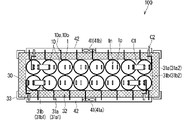
- FIG. 1 is a plan view showing a schematic configuration of a module battery 100;
- FIG. 1 is a side view showing a schematic configuration of a module battery 100;
- FIG. 3 is a block diagram relating to temperature control of the module battery 100;
- FIG. 5 is a block diagram relating to temperature control of the module battery 100. As shown in FIG.
- the unit cell 1 uses metallic sodium (Na) and sulfur (S) as active materials, and beta alumina, which is a solid electrolyte having Na ion conductivity, as a separator separating the two. It is a high-temperature secondary battery having a structure in which a cylindrical exterior portion 1b coaxial with the side surface (side peripheral surface) of a bottomed cylindrical battery main body 1a is ring-mounted. At one end of the battery body 1a, a positive electrode terminal 1p and a negative electrode terminal 1n protrude from the peripheral portion and the central portion, respectively.
- a coil 10 is provided on the outer surface of the cell 1 by winding a pipe (hollow metal wire or thin tube) made of metal (for example, made of copper or aluminum). .
- the exterior part 1 b is composed of a cylindrical metal part 5 that contacts the outer surface (made of alumina) of the battery body 1 a and a similarly cylindrical insulating part 6 that contacts the outer surface of the metal part 5 .
- the metal part 5 further has a two-layer structure in which an inner tube 5a and an outer tube 5b are concentrically laminated.
- the inner tube 5a also called a sheath tube, is made of metal and is provided to prevent deformation of the battery body 1a (to restrain deformation of the battery body 1a), which becomes hot during use and standby of the module battery 100. It is a cylindrical member (made of stainless steel, for example). In order to achieve this purpose, the inner tube 5a may be provided with a thickness of several hundred ⁇ m to several mm.
- the outer tube 5b is made of metal ( It is a cylindrical member made of steel, for example.
- the coil 10 is provided on the outer surface of the cell 1 as described above, and the outer tube 5b is a heating power source 20 which is a predetermined AC power source (AC current generator) provided in the module battery 100.
- AC current generator AC current generator
- the induction-heated outer tube 5b serves as a heat source to heat the single cell 1.
- the inner tube 5 a may also be induction-heated to contribute to the heating of the unit cell 1 .
- the thickness of the outer tube 5b, the thickness of the pipe in the coil 10, the number of turns, and the like may be appropriately determined so that the heating of the single cell 1 by induction heating can be suitably achieved.
- the outer tube 5b is usually provided with a thickness that allows the unit cell 1 to be heated and the outer tube 5b to have a mass equal to the heat capacity of the outer tube 5b.
- the outer tube 5b that satisfies such conditions one having an outer diameter of about 100 mm and a thickness of about 3 mm is exemplified.
- the metal part 5 has a two-layer structure of the inner tube 5a and the outer tube 5b, and the metal part 5 must have the performance required for each of the inner tube 5a and the outer tube 5b.
- the insulating part 6 is a cylindrical member mainly made of an insulating material (eg, mica) provided to insulate the metal part 5 and the coil 10 from each other.
- the insulating portion 6 is provided with a thickness that does not hinder the induction heating of the outer tube 5b while providing suitable insulation.
- a module battery 100 is formed by housing a plurality of unit cells 1 (also referred to as assembled batteries) each having the above configuration in a container 30. is configured.
- the storage container 30 is generally a rectangular parallelepiped container in which the outer surface 31a and the inner surface 31b are made of metal plates, and a heat insulating material 32 is filled between the metal plates on the side and bottom surfaces.
- the pair of outer surfaces 31a and the pair of inner surfaces 31b along the longitudinal direction in plan view of the container 30 will be referred to as an outer surface 31a1 and the inner surface 31b1, respectively, and the pair of outer surfaces 31a and the pair of inner surfaces along the width direction in plan view.
- 31b are referred to as an outer surface 31a2 and an inner surface 31b2, respectively.
- the container 30 is supported by a support frame 33 at its bottom and side portions.
- each of the pair of outer surfaces 31a1 of the container 30 is provided with a blower 41 (41a, 41b) and a duct 42 (42a, 42b) connected thereto.
- a temperature sensor 35 (FIG. 5), not shown in FIGS. 3 and 4, is provided at an appropriate position inside the container 30 so that the temperature inside the container 30 can be monitored.
- a known temperature sensor can be used as the temperature sensor 35, and the number, arrangement position, type, etc. thereof are appropriately selected as long as they do not hinder the operation of the module battery 100 and allow the desired temperature to be accurately measured. may be defined as
- a lid (not shown) is arranged on the top of the container 30 for the purpose of ensuring heat insulation inside the container 30 .
- the lid body has a configuration in which the outer surface and the inner surface are made of metal plates and the inside is filled with a heat insulating material. Further, the gaps other than the arrangement objects in the container 30 are filled with sand.
- the sand material is filled for the purpose of reducing the impact on the surroundings in the event that a problem such as breakage, abnormal heating, or active material leakage occurs in the unit cell 1 . Examples of the sand material include expanded vermiculite (vermiculite) and silica sand.
- the storage container 30 and the lid body adopt an atmospheric heat insulation structure instead of a vacuum heat insulation structure.
- the thermal conductivity of the thermal insulation material is as small as possible. The following are more preferable. In this case, it is possible to secure the heat insulation necessary for the operation of the module battery 100 without excessively increasing the thickness of the container 30 and the cover, as compared with the case where the vacuum insulation structure is adopted.
- each cylindrical unit cell 1 is arranged along the longitudinal direction in a plan view, with the end on the side where the positive electrode terminal 1p and the negative electrode terminal 1n are provided facing upward. are arranged in two rows and housed in the housing container 30 . In the case shown in FIG. 3, eight cells 1 are arranged in each row. In other words, the shape of the storage container 30 is determined according to the arrangement of the unit cells 1 .
- connection terminal C1 In the storage container 30, one positive terminal 1p and the other negative terminal 1n of the adjacent unit cells 1 are electrically connected to each other through the connection terminal C1, thereby forming a plurality of unit cells 1. are connected in series to form a circuit (string). However, in FIG. 3, only some connection terminals C1 are illustrated.
- external connection terminals C2 for establishing electrical connection with the outside of the container 30 are connected to the four single cells 1 arranged at the ends in the container 30 .
- the external connection terminal C ⁇ b>2 is penetrated to the outside at the side of the container 30 . More specifically, such penetration ensures electrical insulation between the external connection terminal C2 and the outer surface 31a1 and the inner surface 31b1 of the container 30 .
- Both ends 10a and 10b of the coil 10 provided on the outer surface of each unit cell 1 are also penetrated to the outside at the side portion of the container 30, respectively. Such penetration also ensures electrical insulation between the coil 10 and the outer surface 31 a 1 and the inner surface 31 b 1 of the container 30 .
- one end 10 a protrudes into the duct 42 .
- the end 10a is covered with the duct 42.
- the other end portion 10b is exposed to the outside of the container 30.
- both ends 10a and 10b of the coil 10 wound around the outer surface of each cell 1 are connected to a heating power supply provided outside the container 30. 20.
- the coil 10 is provided by winding a hollow pipe. Therefore, in the coil 10, in addition to being energized by the heating power source 20, it is also possible to pass a fluid through its interior.
- the coil 10 capable of both conducting electricity between both ends 10a and 10b and allowing fluid to flow inside (in the pipe) is wound around the battery main body 1a. turned around.
- each unit cell 1 is individually heated by induction heating by the coil 10 during standby.
- a cooling gas of room temperature or low temperature for example, air of room temperature
- the cooling gas is forcibly introduced into the coil 10 from one end 10a protruding into the duct 42, can be discharged from the end 10b.
- the temperature distribution in the storage container 30 is made uniform by heating the individual cells 1 under the same conditions during standby.
- the heat generated in each unit cell 1 formed by winding the coil 10 during charge/discharge is taken away by the cooling gas flowing through the coil 10, thereby equalizing the temperature distribution in the container. be done.
- all the single cells 1 housed in the housing container 30 can be individually heated during standby and discharged heat during charging and discharging. As a result, it is possible to stably ensure the uniformity of temperature in each unit cell 1 both during standby and during charging and discharging.
- each single cell 1 is directly heated by energizing the coil 10, the single cell 1 can be heated more efficiently than in a conventional module battery. Therefore, the battery module 100 according to the present embodiment can be heated with less electric power than the conventional battery module. Thus, in the module battery 100 according to the present embodiment, it is possible to ensure sufficient heat insulation while adopting an atmospheric heat insulation structure.
- the module battery 100 according to the present embodiment as shown in FIG. Adjacent to.
- the single cells arranged in the peripheral portion and the single cells arranged in the central portion in the inside of the storage container, which occurred in the conventional module battery are separated from each other.
- the problem of temperature difference occurring between them is designed not to occur due to the configuration. That is, in the module battery 100 according to the present embodiment, the manner in which the unit cells 1 are accommodated has the effect of further stabilizing the temperature uniformity within the container 30 .
- the storage container 30 only accommodates a total of 16 cells 1 in two rows of 8 cells each.
- the number of unit cells 1 to be accommodated in the container 30 is considerably smaller than that of a conventional module battery in which unit cells are accommodated in a large number of rows and columns in one container.
- the single output of the module battery 100 according to the present embodiment is considerably smaller than that of the conventional module battery.
- the output can be increased by increasing the number of cells per row, but there is a limit to such measures due to the shape (aspect ratio) of the storage container.
- the problem is that a plurality of module batteries 100 are prepared, and a plurality of unit cells 1 (that is, assembled batteries), which are accommodated in respective storage containers 30 and connected to each other, are used as one connection unit, and connected in series and in parallel. It is possible to solve this problem by appropriately making connections so that an output equivalent to that of a conventional module battery can be obtained.
- unit cells 1 that is, assembled batteries
- the storage container 30 has a structure that can be connected (connected or stacked) in a plane or three-dimensional manner, and by using this structure, a plurality of module batteries 100 can be arranged in one storage container with a large number of single cells. It is arranged in an occupied area or occupied volume equivalent to that of a conventional module battery.
- each module battery 100 is provided with a storage container 30 having a heat insulating structure, and the temperature uniformity in the storage container 30 during standby and charging/discharging is independently ensured. Therefore, even if the occupied area or occupied volume is equivalent to that of the conventional module battery, the problem of uneven temperature does not occur.
- the module battery 100 according to the present embodiment is superior to the conventional module battery in terms of the stability of the temperature uniformity in the container. It is also possible to operate at high output, which could not be performed due to the occurrence of
- FIG. 5 is a block diagram relating to temperature control of the module battery 100. As shown in FIG. Temperature control of the module battery 100 during standby and charging/discharging is performed by a controller 50 of the module battery 100 provided separately from the main body shown in FIGS.
- the controller 50 mainly includes a battery operation control unit 51 that controls the operation of the module battery 100 during standby and charging/discharging, and a temperature control unit 52 that controls the temperature of the container 30 both during standby and during charging/discharging. Prepare for.
- the controller 50 can be realized by executing a predetermined operation program in a dedicated or general-purpose computer (not shown) equipped with a CPU, memory, storage, etc.
- a battery operation control unit 51 and a temperature control unit 52 is implemented as a virtual component in such a computer.
- the temperature control unit 52 includes a blower control unit 53 and a heating control unit 54.
- the on/off of the blowing operation of the blowers 41 (41a, 41b) is controlled under the control of the blower control unit 53, so that the single cell generates heat due to the reaction of the active material. 1 cooling is done.
- the heating control unit 54 under the control of the heating control unit 54, the on/off of the energization operation of the heating power source 20 is controlled, so that the temperature of the cell 1 in the container 30 is set to a predetermined standby temperature (for example, 300 °C).
- the inside of the storage container 30 is uniformly maintained at a desired temperature both during charging and discharging and during standby.
- a coil is formed by winding a metal pipe around the outer surface of a unit cell housed in a housing container in a module battery of a high-temperature operation type secondary battery. is provided, and by energizing the coil, it is possible to induction-heat the metal part provided on the exterior part of the unit cell, and by circulating cooling gas through the pipe, it is possible to exhaust heat from the unit cell. Heating during standby and exhausting heat during charge/discharge can be performed individually for each unit cell housed in the container.
- all the single cells are housed in the storage container so as to be adjacent to the storage container, and no single cell is surrounded only by other single cells.
- a module battery with improved performance is realized.
- the coil 10 is provided by a metal pipe, and electricity and cooling gas can flow between both ends 10a and 10b of the coil 10.
- an appropriate alternative means may be adopted for cooling during charging and discharging, but at least the unit cells 1 are accommodated in two rows to ensure uniformity of temperature in the container 30. can be obtained to a certain extent by suitably determining the size and performance of the cell 1, the heat insulating performance of the storage container 30, and the like.
Abstract
Description
図1および図2はそれぞれ、本実施の形態に係る単電池1の概略的な構成を示す側面図および平面図である。図3および図4はそれぞれ、本実施の形態に係るモジュール電池100の(より詳細にはその本体部の)概略的な構成を示す平面図および側面図である。図5は、モジュール電池100の温度制御に係るブロック図である。 <Structure of cell and module battery>
1 and 2 are a side view and a plan view, respectively, showing a schematic configuration of a
図5は、モジュール電池100の温度制御に関するブロック図である。モジュール電池100における待機時および充放電時の温度制御は、図3および図4に図示した本体部とは別体に設けられたモジュール電池100のコントローラ50により行われる。 <Temperature control in module battery>
FIG. 5 is a block diagram relating to temperature control of the
上述の実施の形態においては、コイル10が金属製のパイプにて設けられてなり、該コイル10の両端10a、10bの間において通電と冷却気体の流通とが可能となっているが、コイル10を導電性を有する(金属その他の)中実の線材にて設け、通電による加熱のみが行える構成の場合も、待機時に関しては、上述の実施の形態と同様の効果を得ることが可能である。係る場合、充放電時の冷却に関しては、適宜の代替手段が採用されてよいが、少なくとも、単電池1を2列に収容することにより収容容器30内の温度の均一性を確保するという作用効果については、単電池1のサイズおよび性能、収容容器30の断熱性能などが好適に定められることで、一定程度得ることが出来る。 <Modification>
In the above-described embodiment, the
Claims (6)
- 高温動作型の二次電池の単電池であって、
正極部と負極部とを備える円筒状の本体部と、
前記本体部の周囲に環装されてなり、少なくとも円筒状の金属部と前記金属部の外側面に環装された絶縁部とを含む外装部と、
導電性の線材が巻回されることによって前記絶縁部の外側面に設けられたコイルと、
を備える
ことを特徴とする、高温動作型の二次電池の単電池。 A single cell of a high-temperature operation type secondary battery,
a cylindrical body portion including a positive electrode portion and a negative electrode portion;
an exterior portion that is ringed around the main body and includes at least a cylindrical metal portion and an insulating portion that is ringed around the outer surface of the metal portion;
a coil provided on the outer surface of the insulating portion by winding a conductive wire;
A unit cell of a high-temperature operation type secondary battery, comprising: - 請求項1に記載の高温動作型の二次電池の単電池であって、
前記金属部が、
前記本体部の外側面と接触させて設けられ、前記本体部の変形を拘束する内管と、
前記内管の外側面と接触させて設けられた外管と、
の2層構成を有してなり、
前記金属部においては、少なくとも前記外管が、前記コイルの両端部間に高周波交流電流が通電されることにより誘導加熱される、
ことを特徴とする、高温動作型の二次電池の単電池。 A single cell of the high-temperature operation type secondary battery according to claim 1,
The metal part
an inner tube that is provided in contact with the outer surface of the main body and restrains deformation of the main body;
an outer tube provided in contact with the outer surface of the inner tube;
having a two-layer configuration of
In the metal part, at least the outer tube is induction-heated by applying a high-frequency alternating current between both ends of the coil.
A unit cell of a high-temperature operation type secondary battery characterized by: - 請求項1または請求項2に記載の高温動作型の二次電池の単電池であって、
前記線材が中空の金属製のパイプである、
ことを特徴とする、高温動作型の二次電池の単電池。 A single cell of the high-temperature operation type secondary battery according to claim 1 or claim 2,
The wire rod is a hollow metal pipe,
A unit cell of a high-temperature operation type secondary battery characterized by: - 高温動作型の二次電池のモジュール電池であって、
断熱構造を有する収容容器と、
前記収容容器に収容された、それぞれが請求項1ないし請求項3のいずれかに記載の単電池である複数の単電池と、
前記複数の単電池のそれぞれに備わる前記コイルに高周波交流電流を通電可能な少なくとも一つの高周波交流電流発生装置と、
を備え、
前記高周波交流電流発生装置が前記コイルに前記高周波交流電流を通電することによって前記金属部が誘導加熱され、
前記収容容器においては、前記複数の単電池の全てが前記収容容器と隣接する、
ことを特徴とするモジュール電池。 A secondary battery module battery that operates at high temperature,
a container having a heat insulating structure;
a plurality of single cells, each of which is the single cell according to any one of claims 1 to 3, housed in the container;
at least one high-frequency alternating current generator capable of applying a high-frequency alternating current to the coils provided in each of the plurality of cells;
with
The high-frequency alternating current generator energizes the coil with the high-frequency alternating current to heat the metal part by induction,
In the container, all of the plurality of cells are adjacent to the container,
A module battery characterized by: - 高温動作型の二次電池のモジュール電池であって、
断熱構造を有する収容容器と、
前記収容容器に収容された、それぞれが請求項3に記載の単電池である複数の単電池と、
前記複数の単電池のそれぞれに備わる前記コイルに高周波交流電流を通電可能な少なくとも一つの高周波交流電流発生装置と、
前記収容容器の側部に付設されたダクトと、
前記ダクトに対して冷却気体を供給可能なブロアと、
を備え、
前記高周波交流電流発生装置が前記コイルに前記高周波交流電流を通電することによって前記金属部が誘導加熱され、
前記コイルの一方端部が前記収容容器の側部を貫通して前記ダクト内に延在してなり、
前記コイルの他方端部が前記収容容器の側部を貫通して外部に延在してなり、
前記ブロアが供給した前記冷却気体が前記コイルの内部を流通することで前記複数の単電池のそれぞれにおいて生じる熱が排出される、
ことを特徴とするモジュール電池。 A secondary battery module battery that operates at high temperature,
a container having a heat insulating structure;
a plurality of single cells, each of which is the single cell according to claim 3, housed in the container;
at least one high-frequency alternating current generator capable of applying a high-frequency alternating current to the coils provided in each of the plurality of cells;
a duct attached to the side of the container;
a blower capable of supplying cooling gas to the duct;
with
The high-frequency alternating current generator energizes the coil with the high-frequency alternating current to heat the metal part by induction,
one end of the coil extends into the duct through the side of the container,
The other end of the coil extends outside through the side of the container,
Heat generated in each of the plurality of cells is discharged by the cooling gas supplied by the blower circulating inside the coil,
A module battery characterized by: - 請求項5に記載の高温動作型の二次電池のモジュール電池であって、
前記収容容器においては、前記複数の単電池の全てが前記収容容器と隣接する、
ことを特徴とするモジュール電池。 The module battery of the high-temperature operation type secondary battery according to claim 5,
In the container, all of the plurality of cells are adjacent to the container,
A module battery characterized by:
Priority Applications (3)
| Application Number | Priority Date | Filing Date | Title |
|---|---|---|---|
| EP22815851.5A EP4350843A1 (en) | 2021-05-31 | 2022-05-18 | Unit battery and module battery for high-temperature-operation secondary battery |
| JP2023525713A JPWO2022255099A1 (en) | 2021-05-31 | 2022-05-18 | |
| US18/519,173 US20240088470A1 (en) | 2021-05-31 | 2023-11-27 | Battery cell and module battery for high-temperature operating secondary battery |
Applications Claiming Priority (2)
| Application Number | Priority Date | Filing Date | Title |
|---|---|---|---|
| JP2021-090970 | 2021-05-31 | ||
| JP2021090970 | 2021-05-31 |
Related Child Applications (1)
| Application Number | Title | Priority Date | Filing Date |
|---|---|---|---|
| US18/519,173 Continuation US20240088470A1 (en) | 2021-05-31 | 2023-11-27 | Battery cell and module battery for high-temperature operating secondary battery |
Publications (1)
| Publication Number | Publication Date |
|---|---|
| WO2022255099A1 true WO2022255099A1 (en) | 2022-12-08 |
Family
ID=84323315
Family Applications (1)
| Application Number | Title | Priority Date | Filing Date |
|---|---|---|---|
| PCT/JP2022/020618 WO2022255099A1 (en) | 2021-05-31 | 2022-05-18 | Unit battery and module battery for high-temperature-operation secondary battery |
Country Status (4)
| Country | Link |
|---|---|
| US (1) | US20240088470A1 (en) |
| EP (1) | EP4350843A1 (en) |
| JP (1) | JPWO2022255099A1 (en) |
| WO (1) | WO2022255099A1 (en) |
Citations (7)
| Publication number | Priority date | Publication date | Assignee | Title |
|---|---|---|---|---|
| JPH10294127A (en) * | 1997-04-21 | 1998-11-04 | Hitachi Ltd | Manufacture and manufacturing apparatus for sodium-sulfur battery |
| US20020025471A1 (en) * | 2000-08-24 | 2002-02-28 | Velez Thomas A. | Electrially heated thermal battery |
| JP2004111123A (en) * | 2002-09-17 | 2004-04-08 | Ngk Insulators Ltd | Method for controlling heater for sodium-sulfur battery module |
| JP2011060477A (en) * | 2009-09-08 | 2011-03-24 | Toshihisa Shirakawa | SUBCRITICAL AMOUNT RECESSIVE PLUTONIUM HEATING SOURCE NaS MODULE STORAGE BATTERY POWER SOURCE DRIVING ELECTRIC VEHICLE |
| JP2012528458A (en) * | 2009-05-26 | 2012-11-12 | シーレイト リミテッド ライアビリティー カンパニー | System and method for changing the temperature of an electrical energy storage device or electrochemical energy generation device using a microchannel |
| WO2015056739A1 (en) | 2013-10-17 | 2015-04-23 | 日本碍子株式会社 | Secondary battery |
| WO2019221860A1 (en) * | 2018-05-17 | 2019-11-21 | Vissers Battery Corporation | Devices, systems, and methods to mitigate thermal runaway conditions in molten fluid electrode apparatus |
-
2022
- 2022-05-18 JP JP2023525713A patent/JPWO2022255099A1/ja active Pending
- 2022-05-18 WO PCT/JP2022/020618 patent/WO2022255099A1/en active Application Filing
- 2022-05-18 EP EP22815851.5A patent/EP4350843A1/en active Pending
-
2023
- 2023-11-27 US US18/519,173 patent/US20240088470A1/en active Pending
Patent Citations (7)
| Publication number | Priority date | Publication date | Assignee | Title |
|---|---|---|---|---|
| JPH10294127A (en) * | 1997-04-21 | 1998-11-04 | Hitachi Ltd | Manufacture and manufacturing apparatus for sodium-sulfur battery |
| US20020025471A1 (en) * | 2000-08-24 | 2002-02-28 | Velez Thomas A. | Electrially heated thermal battery |
| JP2004111123A (en) * | 2002-09-17 | 2004-04-08 | Ngk Insulators Ltd | Method for controlling heater for sodium-sulfur battery module |
| JP2012528458A (en) * | 2009-05-26 | 2012-11-12 | シーレイト リミテッド ライアビリティー カンパニー | System and method for changing the temperature of an electrical energy storage device or electrochemical energy generation device using a microchannel |
| JP2011060477A (en) * | 2009-09-08 | 2011-03-24 | Toshihisa Shirakawa | SUBCRITICAL AMOUNT RECESSIVE PLUTONIUM HEATING SOURCE NaS MODULE STORAGE BATTERY POWER SOURCE DRIVING ELECTRIC VEHICLE |
| WO2015056739A1 (en) | 2013-10-17 | 2015-04-23 | 日本碍子株式会社 | Secondary battery |
| WO2019221860A1 (en) * | 2018-05-17 | 2019-11-21 | Vissers Battery Corporation | Devices, systems, and methods to mitigate thermal runaway conditions in molten fluid electrode apparatus |
Also Published As
| Publication number | Publication date |
|---|---|
| US20240088470A1 (en) | 2024-03-14 |
| EP4350843A1 (en) | 2024-04-10 |
| JPWO2022255099A1 (en) | 2022-12-08 |
Similar Documents
| Publication | Publication Date | Title |
|---|---|---|
| JP2022523625A (en) | Battery pack heat management methods and systems | |
| US4383013A (en) | High temperature multicell electrochemical storage batteries | |
| US20160111760A1 (en) | Power storage module | |
| US20170162921A1 (en) | Electrical Energy Storage Device | |
| US20160111762A1 (en) | Electrical storage apparatus | |
| EP2793310B1 (en) | Cell module provided with cell block | |
| EP0044753B1 (en) | Electrochemical storage batteries and modules therefor | |
| US20160190666A1 (en) | Battery-pack case | |
| CN108140910B (en) | Heat flux assembly for an energy storage device | |
| WO2022255099A1 (en) | Unit battery and module battery for high-temperature-operation secondary battery | |
| US20230307744A1 (en) | Electric Battery Assembly | |
| JP2022505501A (en) | Solid oxide electrochemical system with built-in heating means | |
| JPH01122575A (en) | Method of avoiding overheat of high temperature battery | |
| CN110915029B (en) | Charging/discharging apparatus for secondary battery formation process with reduced temperature difference | |
| JP2966292B2 (en) | Heating apparatus for assembled battery comprising sodium-sulfur battery, assembled battery provided therewith, and heating method | |
| JP2014127403A (en) | Battery module | |
| JP2013196955A (en) | Power storage device | |
| JP6970562B2 (en) | Heater for hot air generation | |
| JP2003234131A (en) | Heating device of collective battery composed of sodium- sulfur cell | |
| JP2003234132A (en) | Heating device of collective battery composed of sodium- sulfur cell | |
| JP2582175B2 (en) | Sodium sulfur battery module | |
| JP6100574B2 (en) | Fuel cell module and fuel cell device | |
| WO2023006725A1 (en) | Electrochemical energy storage device | |
| JP2009181823A (en) | Fuel cell module and fuel cell | |
| JPWO2022255099A5 (en) |
Legal Events
| Date | Code | Title | Description |
|---|---|---|---|
| 121 | Ep: the epo has been informed by wipo that ep was designated in this application |
Ref document number: 22815851 Country of ref document: EP Kind code of ref document: A1 |
|
| WWE | Wipo information: entry into national phase |
Ref document number: 2023525713 Country of ref document: JP |
|
| WWE | Wipo information: entry into national phase |
Ref document number: 2022815851 Country of ref document: EP |
|
| NENP | Non-entry into the national phase |
Ref country code: DE |
|
| ENP | Entry into the national phase |
Ref document number: 2022815851 Country of ref document: EP Effective date: 20240102 |