WO2022254996A1 - Processing device - Google Patents
Processing device Download PDFInfo
- Publication number
- WO2022254996A1 WO2022254996A1 PCT/JP2022/018560 JP2022018560W WO2022254996A1 WO 2022254996 A1 WO2022254996 A1 WO 2022254996A1 JP 2022018560 W JP2022018560 W JP 2022018560W WO 2022254996 A1 WO2022254996 A1 WO 2022254996A1
- Authority
- WO
- WIPO (PCT)
- Prior art keywords
- time
- value
- processing device
- signal
- arithmetic circuit
- Prior art date
Links
- 238000012545 processing Methods 0.000 title claims abstract description 221
- 238000004891 communication Methods 0.000 claims description 23
- 238000012217 deletion Methods 0.000 claims description 9
- 230000037430 deletion Effects 0.000 claims description 9
- 238000000034 method Methods 0.000 description 13
- 238000012986 modification Methods 0.000 description 13
- 230000004048 modification Effects 0.000 description 13
- 238000010586 diagram Methods 0.000 description 12
- 238000004458 analytical method Methods 0.000 description 11
- WLRMANUAADYWEA-NWASOUNVSA-N (S)-timolol maleate Chemical compound OC(=O)\C=C/C(O)=O.CC(C)(C)NC[C@H](O)COC1=NSN=C1N1CCOCC1 WLRMANUAADYWEA-NWASOUNVSA-N 0.000 description 10
- XLOMVQKBTHCTTD-UHFFFAOYSA-N Zinc monoxide Chemical compound [Zn]=O XLOMVQKBTHCTTD-UHFFFAOYSA-N 0.000 description 8
- 230000000694 effects Effects 0.000 description 6
- 239000004626 polylactic acid Substances 0.000 description 5
- 238000005070 sampling Methods 0.000 description 5
- 230000000052 comparative effect Effects 0.000 description 4
- 229920000747 poly(lactic acid) Polymers 0.000 description 4
- 239000011787 zinc oxide Substances 0.000 description 4
- 238000006243 chemical reaction Methods 0.000 description 3
- 229920000642 polymer Polymers 0.000 description 3
- BQCADISMDOOEFD-UHFFFAOYSA-N Silver Chemical compound [Ag] BQCADISMDOOEFD-UHFFFAOYSA-N 0.000 description 2
- 239000012790 adhesive layer Substances 0.000 description 2
- 230000003321 amplification Effects 0.000 description 2
- 230000006835 compression Effects 0.000 description 2
- 238000007906 compression Methods 0.000 description 2
- 238000001514 detection method Methods 0.000 description 2
- AMGQUBHHOARCQH-UHFFFAOYSA-N indium;oxotin Chemical compound [In].[Sn]=O AMGQUBHHOARCQH-UHFFFAOYSA-N 0.000 description 2
- 229910052751 metal Inorganic materials 0.000 description 2
- 239000002184 metal Substances 0.000 description 2
- 238000003199 nucleic acid amplification method Methods 0.000 description 2
- 238000007747 plating Methods 0.000 description 2
- 229910052709 silver Inorganic materials 0.000 description 2
- 239000004332 silver Substances 0.000 description 2
- 238000007740 vapor deposition Methods 0.000 description 2
- 241000288673 Chiroptera Species 0.000 description 1
- 230000005540 biological transmission Effects 0.000 description 1
- 230000003247 decreasing effect Effects 0.000 description 1
- 229920006381 polylactic acid film Polymers 0.000 description 1
Images


Classifications
-
- A—HUMAN NECESSITIES
- A63—SPORTS; GAMES; AMUSEMENTS
- A63B—APPARATUS FOR PHYSICAL TRAINING, GYMNASTICS, SWIMMING, CLIMBING, OR FENCING; BALL GAMES; TRAINING EQUIPMENT
- A63B69/00—Training appliances or apparatus for special sports
- A63B69/36—Training appliances or apparatus for special sports for golf
- A63B69/3617—Striking surfaces with impact indicating means, e.g. markers
-
- A—HUMAN NECESSITIES
- A63—SPORTS; GAMES; AMUSEMENTS
- A63B—APPARATUS FOR PHYSICAL TRAINING, GYMNASTICS, SWIMMING, CLIMBING, OR FENCING; BALL GAMES; TRAINING EQUIPMENT
- A63B69/00—Training appliances or apparatus for special sports
- A63B69/36—Training appliances or apparatus for special sports for golf
- A63B69/3614—Training appliances or apparatus for special sports for golf using electro-magnetic, magnetic or ultrasonic radiation emitted, reflected or interrupted by the golf club
-
- G—PHYSICS
- G06—COMPUTING; CALCULATING OR COUNTING
- G06V—IMAGE OR VIDEO RECOGNITION OR UNDERSTANDING
- G06V40/00—Recognition of biometric, human-related or animal-related patterns in image or video data
- G06V40/20—Movements or behaviour, e.g. gesture recognition
- G06V40/23—Recognition of whole body movements, e.g. for sport training
-
- G—PHYSICS
- G09—EDUCATION; CRYPTOGRAPHY; DISPLAY; ADVERTISING; SEALS
- G09B—EDUCATIONAL OR DEMONSTRATION APPLIANCES; APPLIANCES FOR TEACHING, OR COMMUNICATING WITH, THE BLIND, DEAF OR MUTE; MODELS; PLANETARIA; GLOBES; MAPS; DIAGRAMS
- G09B19/00—Teaching not covered by other main groups of this subclass
- G09B19/003—Repetitive work cycles; Sequence of movements
- G09B19/0038—Sports
-
- A—HUMAN NECESSITIES
- A63—SPORTS; GAMES; AMUSEMENTS
- A63B—APPARATUS FOR PHYSICAL TRAINING, GYMNASTICS, SWIMMING, CLIMBING, OR FENCING; BALL GAMES; TRAINING EQUIPMENT
- A63B2220/00—Measuring of physical parameters relating to sporting activity
- A63B2220/80—Special sensors, transducers or devices therefor
- A63B2220/83—Special sensors, transducers or devices therefor characterised by the position of the sensor
- A63B2220/833—Sensors arranged on the exercise apparatus or sports implement
-
- A—HUMAN NECESSITIES
- A63—SPORTS; GAMES; AMUSEMENTS
- A63B—APPARATUS FOR PHYSICAL TRAINING, GYMNASTICS, SWIMMING, CLIMBING, OR FENCING; BALL GAMES; TRAINING EQUIPMENT
- A63B69/00—Training appliances or apparatus for special sports
- A63B69/36—Training appliances or apparatus for special sports for golf
Definitions
- the present invention relates to a processing device that detects the moment when a user starts swinging a hitting member such as a golf club.
- a swing analysis device described in Patent Document 1 is known as an invention for analyzing a swing of a golf club by a user.
- a sensor is attached to the shaft of the golf club.
- the swing analysis device analyzes the user's swing based on the signal acquired from the sensor.
- An object of the present invention is to provide a processing device that accurately identifies the moment when the user starts swinging the striking member.
- the inventor of the present application has studied a method of identifying the time when the acquired signal exceeds the judgment value as the swing start time as a method of accurately identifying the moment when the user starts swinging the striking member.
- the determination value is set based on the value of the signal generated by the swing.
- the processing device detects the time when the value of the signal obtained from the sensor exceeds the judgment value as the swing start time.
- the inventor of the present application has noticed that the impact may be applied to the striking member by actions other than swinging by the user. Actions other than swinging are, for example, actions in which the user erroneously knocks down the striking member. In this case, the inventor of the present application has noticed that there is a possibility that a force of the same degree as the force generated by the swing may be applied to the striking member. As a result, the inventor of the present application has noticed that the processing device may erroneously detect a motion other than the swing as the start of the swing.
- the inventor of the present application considered the usage of the striking member.
- the inventors of the present application have found that the moment when the striking member receives the strongest impact is the moment of impact when the striking member collides with the object to be struck. That is, the inventors of the present application have noticed that an impact greater than the impact at the moment of impact is not applied to the striking member.
- the inventors of the present application have found that when the first determination value is set based on the signal value at the moment of impact, the possibility of the processing device erroneously detecting the moment of impact is low.
- the inventor of the present application thought that a processing device with a low possibility of false detection could be provided by the following method.
- the processing device determines that the user has performed a swing motion. Then, the swing start time is specified from the times at which the signal was acquired before the impact time.
- the inventor of the present application re-examined a technique for accurately detecting the moment when a user starts swinging a hitting member such as a golf club.
- a hitting member such as a golf club.
- a processing apparatus includes: A calculation for determining a swing start time based on a first signal obtained from a sensor attached to a striking member for striking an object to be struck by swinging, the sensor detecting deformation of the striking member during swing. circuit, with defining the absolute value of the difference between the reference value and the value of the first signal as a first difference value;
- the arithmetic circuit is a first determination step of determining an impact time based on one or more times at which the first difference value becomes equal to or greater than a first determination value; The most recent period closest to the impact time from among one or more periods in which the first difference value is below the second judgment value over a reference time in the first signal acquired at a time before the impact time. a first identifying step of identifying a second identifying step of identifying a swing start time based on the latest period; to run.
- a processing apparatus includes: A calculation for determining a swing start time based on a first signal obtained from a sensor attached to a striking member for striking an object to be struck by swinging, the sensor detecting deformation of the striking member during swing. circuit, with The time at which the value of the first signal changes from being above the reference value to the state below it, or the time at which the value of the first signal changes from being below the reference value to being above the reference value.
- the arithmetic circuit is a first determination step of determining an impact time based on one or more times at which the first difference value becomes equal to or greater than a first determination value; a first identifying step of identifying one or more cross times in a first signal acquired at a time before the impact time; a second specifying step of specifying a swing start time based on the cross time closest to the impact time by a reference number among the one or more cross times; to run.
- shafts and members extending in the front-rear direction do not necessarily indicate only shafts and members parallel to the front-rear direction.
- a shaft or member extending in the front-rear direction is a shaft or member that is inclined within a range of ⁇ 45° with respect to the front-rear direction.
- the shafts and members that extend in the vertical direction are shafts and members that are inclined within a range of ⁇ 45° with respect to the vertical direction.
- An axis or member extending in the left-right direction is an axis or member that is inclined within a range of ⁇ 45° with respect to the left-right direction.
- the first member and the second member are structures provided in the sensor device.
- the first member being arranged on the second member refers to the following state. At least a portion of the first member is located directly above the second member. Therefore, when viewed in the vertical direction, the first member overlaps the second member. This definition also applies to directions other than the vertical direction.
- the first member is arranged above the second member means that at least part of the first member is positioned directly above the second member, and that the first member is positioned above the second member. This includes the case where the first member is positioned obliquely above the second member without being positioned directly above the member. In this case, the first member does not have to overlap the second member when viewed in the vertical direction. For example, diagonally upward means upper left and upper right. This definition also applies to directions other than the vertical direction.
- each part of the first member is defined as follows.
- front of the first member is meant the front half of the first member.
- a rear portion of the first member means the rear half of the first member.
- the left portion of the first member means the left half of the first member.
- the right portion of the first member means the right half of the first member.
- top of the first member is meant the top half of the first member.
- a lower portion of the first member means a lower half of the first member.
- the front end of the first member means the front end of the first member.
- the rear end of the first member means the rearward end of the first member.
- the left end of the first member means the left end of the first member.
- the right end of the first member means the right end of the first member.
- the upper end of the first member means the upper end of the first member.
- the lower end of the first member means the downward end of the first member.
- the front end of the first member means the front end of the first member and its vicinity.
- the rear end of the first member means the rear end of the first member and its vicinity.
- the left end of the first member means the left end of the first member and its vicinity.
- the right end of the first member means the right end of the first member and its vicinity.
- the upper end of the first member means the upper end of the first member and its vicinity.
- the lower end of the first member means the lower end of the first member and its vicinity.
- the processing device can accurately identify the moment when the user starts swinging the striking member.
- FIG. 1 is a diagram showing an example of a striking member 1 to which a sensor 10, an AD converter 20 and a processing device 30 are attached.
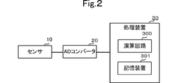
- FIG. 2 is a block diagram of the sensor 10, AD converter 20 and processor 30.
- FIG. 3A and 3B are rear and left side views of the sensor 10.
- FIG. 4 is a diagram showing an example of the first signal DSig1 output from the sensor 10 to the processing device 30.
- FIG. 5 is a flow chart showing the processing executed by the processing device 30.
- FIG. 6 is a flow chart showing the processing executed by the processing device 30a.
- FIG. 7 is a diagram showing an example of the third specifying step executed by the arithmetic circuit 300a.
- FIG. 8 is a flow chart showing the processing executed by the processing device 30b.
- FIG. 9 is a graph showing an example of the swing start time specified by the processing of the arithmetic circuit 300c.
- FIG. 10 is a flow chart showing the processing executed by the processing device 30c.
- FIG. 11 is a diagram showing an example of communication between the processing device 30d and the second processing device 40.
- FIG. 12 is a diagram showing an example of a deletion step executed by the processing device 30e.
- FIG. 1 is a diagram showing an example of a striking member 1 to which a sensor 10, an AD converter 20 and a processing device 30 are attached.
- FIG. 2 is a block diagram of the sensor 10, AD converter 20 and processor 30.
- FIG. 3A and 3B are rear and left side views of the sensor 10.
- FIG. 4 is a diagram showing an example of the first signal DSig1 output from the sensor 10 to the processing device 30.
- the vertical axis indicates signal output.
- the horizontal axis indicates time.
- FIG. 5 is a flow chart showing the processing executed by the processing device 30. As shown in FIG.
- the up-down direction, the left-right direction, and the front-rear direction are defined.
- the direction in which the shaft of the striking member 1 extends is defined as the vertical direction.
- the direction in which the face of the head of the striking member 1 faces is defined as the left direction.
- a direction orthogonal to the up-down direction and the left-right direction is defined as the front-rear direction.
- the up-down direction, the left-right direction, and the front-rear direction are directions defined for explanation. Therefore, the up-down direction, left-right direction and front-back direction of the striking member 1 during actual use need not coincide with the up-down direction, left-right direction and front-back direction shown in FIG.
- the hitting member 1 is a member for hitting an object to be hit.
- the striking member 1 is a golf club. Therefore, in this embodiment, the striking member 1 has a bar shape extending in the vertical direction.
- a user hits an object to be hit by swinging the hitting member 1 .
- the striking member 1 deforms. Specifically, when the user swings the hitting member 1, the hitting member 1 is deformed by inertial force and external force. The striking member 1 deforms in the left-right direction during a swing, for example.
- the sensor 10, the AD converter 20 and the processing device 30 are attached to the striking member 1 for striking the object by swinging. As shown in FIG. 1, in this embodiment, a sensor 10, an AD converter 20 and a processor 30 are fixed to the striking member 1. As shown in FIG. 1, in this embodiment, a sensor 10, an AD converter 20 and a processor 30 are fixed to the striking member 1. As shown in FIG.
- the sensor 10 detects deformation of the striking member 1 during swing. Specifically, the sensor 10 generates an electric charge according to the deformation of the striking member 1 .
- the sensor 10 converts the charge into a first signal Sig1, which is a voltage signal. Therefore, in this embodiment, the value of the first signal Sig1 is a value corresponding to the deformation amount of the striking member 1 in the left-right direction.
- the striking member 1 is elastically deformed. Therefore, the deformation amount of the hitting member 1 in the left-right direction is proportional to the force applied to the hitting member 1 when the user swings. In other words, the value of the first signal Sig1 indirectly indicates the force applied when the user swings the striking member 1 .
- the time at which the user started swinging the striking member 1 can be estimated from the value of the first signal Sig1.
- the value of the first signal Sig1 detected by the sensor 10 is small before and after the start of the swing.
- the period when the value of the first signal Sig1 is small includes the time when the user starts swinging.
- swing start time SwT the time when the user starts swinging the striking member 1 is referred to as swing start time SwT.
- the time at which the striking member 1 impacts the object to be struck is estimated from the value of the first signal Sig1. For example, at the moment when the user hits an object to be hit with the hitting member 1, the amount of deformation of the hitting member 1 is large. Therefore, the value of the first signal Sig1 detected by the sensor 10 is large. In other words, it can be inferred that the period when the value of the first signal Sig1 detected by the sensor 10 is large includes the time when the striking member 1 impacts the object to be struck.
- the time at which the hitting member 1 hits the object to be hit will be referred to as impact time InT.
- the sensor 10 is a piezoelectric sensor that detects pressure.
- the sensor 10 includes a piezoelectric film 100, a first electrode 101F, a second electrode 101B, a charge amplifier 102 and a voltage amplifier circuit 103, as shown in FIG.
- the piezoelectric film 100 has a sheet shape. Therefore, the piezoelectric film 100 has a first main surface F1 and a second main surface F2, as shown in FIG.
- the vertical length of the piezoelectric film 100 is longer than the horizontal length of the piezoelectric film 100 .
- the piezoelectric film 100 has a rectangular shape with long sides extending in the vertical direction when viewed in the front-rear direction.
- the piezoelectric film 100 generates electric charges according to the amount of deformation of the piezoelectric film 100 .
- the piezoelectric film 100 is a PLA film. The piezoelectric film 100 will be described in more detail below.
- piezoelectric film 100 is a film formed from a chiral polymer.
- a chiral polymer is, for example, polylactic acid (PLA), particularly L-type polylactic acid (PLLA).
- PLA polylactic acid
- PLLA L-type polylactic acid
- a PLLA composed of a chiral polymer has a helical structure in its main chain.
- PLLA is uniaxially stretched and has piezoelectricity in which the molecules are oriented.
- the piezoelectric film 100 has a piezoelectric constant of d14.
- the uniaxial stretching direction (orientation direction) of the piezoelectric film 100 forms an angle of 45 degrees with respect to each of the vertical direction and the horizontal direction. This 45 degrees includes angles including, for example, about 45 degrees ⁇ 10 degrees. Accordingly, the piezoelectric film 100 generates an electric charge by being deformed such that the piezoelectric film 100 is stretched in the vertical direction or deformed by being stretched in the vertical direction. The piezoelectric film 100 generates a positive electric charge when it is deformed, for example, by being elongated in the vertical direction. For example, the piezoelectric film 100 generates negative charges when deformed so as to be elongated in the left-right direction. The magnitude of the charge depends on the amount of deformation of the piezoelectric film 100 due to stretching or compression. The magnitude of the charge is proportional to the differential value of the amount of deformation of the piezoelectric film 100 due to extension or compression.
- the first electrode 101F is a signal electrode.
- the first electrode 101F is provided on the first main surface F1.
- the first electrode 101F covers the first main surface F1.
- the first electrode 101F is, for example, an organic electrode such as ITO (indium tin oxide) or ZnO (zinc oxide), a metal film by vapor deposition or plating, or a printed electrode film by silver paste.
- the second electrode 101B is a ground electrode.
- the second electrode 101B is connected to ground potential.
- the second electrode 101B is provided on the second main surface F2. Thereby, the piezoelectric film 100 is positioned between the first electrode 101F and the second electrode 101B.
- the second electrode 101B covers the second main surface F2.
- the second electrode 101B is, for example, an organic electrode such as ITO (indium tin oxide) or ZnO (zinc oxide), a metal film by vapor deposition or plating, or a printed electrode film by silver paste.
- Such a sensor 10 is fixed to the striking member 1 via an adhesive layer (not shown). Specifically, the adhesive layer fixes the striking member 1 and the first electrode 101F.
- the adhesive layer fixes the striking member 1 and the first electrode 101F.
- the piezoelectric film 100 expands and contracts in the vertical direction.
- the piezoelectric film 100 generates an electric charge. That is, in this embodiment, the piezoelectric film 100 generates a negative charge when the striking member 1 is bent rightward.
- the piezoelectric film 100 when the striking member 1 is bent leftward, the piezoelectric film 100 generates a positive charge.
- the charge amplifier 102 converts the charge generated by the piezoelectric film 100 into a first signal Sig1, which is a voltage signal. For example, charge amplifier 102 converts the charge to a voltage value in the range of 0.0V to 3.0V. After conversion, the charge amplifier 102 outputs the first signal Sig1 to the voltage amplifier circuit 103 .
- the voltage amplification circuit 103 amplifies the first signal Sig1 and outputs it to the AD converter 20 .
- the processing device 30 determines the swing start time SwT of the hitting member 1 by the user based on the first signal DSig1.
- the processing device 30 includes an arithmetic circuit 300 and a storage device 301, as shown in FIG.
- the storage device 301 stores a program for determining the swing start time SwT.
- the storage device 301 includes, for example, ROM (Read Only Memory) and RAM (Random Access Memory).
- the arithmetic circuit 300 reads the program stored in the ROM to the RAM. Accordingly, the arithmetic circuit 300 performs processing for determining the swing start time SwT.
- Such an arithmetic circuit 300 is, for example, a CPU (Central Processing Unit).
- This process starts when the processing device 30 acquires the first signal DSig1 from the sensor 10 . Specifically, first, the arithmetic circuit 300 acquires the first signal DSig1 from the sensor 10 ( FIG. 5 : step S10).
- the arithmetic circuit 300 determines whether or not there is one or more times when the absolute value of the difference between the reference value SiV and the value of the first signal DSig1 is equal to or greater than the first determination value 1stTh ( FIG. 5 : step S11).
- the arithmetic circuit 300 calculates the absolute value of the difference between the reference value SiV and the value of the first signal DSig1.
- the value of the first signal DSig1 is "3" and the reference value SiV is "2048" will be described below as an example.
- the value obtained by subtracting the reference value SiV from the first signal DSig1 is "-2045". Therefore, the arithmetic circuit 300 calculates the absolute value of the difference as "2045".
- the absolute value of the difference between the reference value SiV and the value of the first signal DSig1 is defined as a first difference value DV1.
- the arithmetic circuit 300 determines whether the first difference value DV1 is greater than or equal to the first determination value 1stTh.
- the first determination value 1stTh is a value stored in the processing device 30 .
- FIG. 4 An example of FIG. 4 will be described below.
- the first signal DSig1 is "3" or less.
- the reference value SiV is "2048”. Therefore, the first difference value DV1 is "2045".
- the first determination value 1stTh is "2045". Therefore, at time TT, the first difference value DV1 is greater than or equal to the first determination value 1stTh.
- the arithmetic circuit 300 determines the time TT as the time when the absolute value of the difference between the reference value SiV and the value of the first signal DSig1 becomes equal to or greater than the first determination value 1stTh.
- the time when the first difference value DV1 becomes equal to or greater than the first determination value 1stTh will be referred to as the first time.
- step S11 No When the arithmetic circuit 300 determines that there is no time at which the first difference value DV1 is equal to or greater than the first determination value 1stTh at one time or more ( FIG. 5 : step S11 No), the processing device 30 performs step S10. Return processing to before .
- the arithmetic circuit 300 determines that there is one or more times at which the first difference value DV1 is equal to or greater than the first judgment value 1stTh (FIG. 5: step S11 Yes)
- the arithmetic circuit 300 performs the first A first determination step of determining the time at which the first difference value DV1 becomes the largest among the one or more times at which the difference value DV1 becomes equal to or greater than the first determination value 1stTh as the impact time InT is executed (FIG. 5: step S12).
- the arithmetic circuit 300 determines the time TT as the first time.
- the arithmetic circuit 300 does not determine a time other than the time TT as the first time. Therefore, the time at which the first difference value DV1 becomes the largest among the one or more times is the time TT.
- the arithmetic circuit 300 determines the time TT as the impact time InT.
- the arithmetic circuit 300 identifies the swing start time SwT by examining the first signal DSig1 acquired at the time BeTime before the impact time InT. Specifically, in the first signal DSig1 acquired at the time BeTime prior to the impact time InT, the arithmetic circuit 300 detects one or more periods in which the first difference value DV1 is below the second determination value 2ndTh over the reference time. A first identification step is executed to identify the most recent period MPE closest to the impact time InT from among the PEs (step S13 in FIG. 5). The first identifying step will be described in detail below.
- the arithmetic circuit 300 identifies one or more periods PE in which the first difference value DV1 is below the second determination value 2ndTh over the reference time at the time BeTime before the impact time InT.
- the value of the second determination value 2ndTh is smaller than the value of the first determination value 1stTh.
- the processing device 30 stores the second determination value 2ndTh as "200". In this case, if the first difference value DV1 is "200" or less, the arithmetic circuit 300 determines that the first difference value DV1 is less than the second determination value 2ndTh.
- the reference time is set to 0.2 seconds, 0.3 seconds, or the like, for example.
- the arithmetic circuit 300 sets the period in which the first difference value DV1 is lower than the second determination value 2ndTh for 0.2 seconds as the period PE Identify as The arithmetic circuit 300 identifies one or more periods PE. Specifically, after identifying the first period PE, the arithmetic circuit 300 identifies whether the period PE exists at a time after the first identified period PE. For example, as shown in FIG. 4, the arithmetic circuit 300 identifies the period PE1 as the period PE. In the example shown in FIG. 4, the period PE exists at a time later than the period PE1. In this case, the arithmetic circuit 300 identifies the period PE that occurred after the period PE1 as the period PE2.
- the arithmetic circuit 300 identifies the most recent period MPE closest to the impact time InT from among one or more periods PE. For example, in the example shown in FIG. 4, the arithmetic circuit 300 identifies periods PE1 and PE2. As shown in FIG. 4, the period PE2 is closer to the impact time InT than the period PE1. Therefore, the arithmetic circuit 300 identifies the period PE2 as the latest period MPE.
- the arithmetic circuit 300 executes a second identification step of identifying the swing start time SwT based on the latest period MPE (step S14 in FIG. 5). For example, the arithmetic circuit 300 identifies the time from the earliest time to the latest time in the latest period MPE as the swing start time SwT. Specifically, when the earliest time in the latest period MPE is 5.0 seconds and the latest time is 5.2 seconds, the arithmetic circuit 300 sets the swing start time SwT to 5.0 seconds. Specify between seconds and 5.2 seconds.
- the processing device 30 identifies the swing start time SwT.
- the arithmetic circuit 300 repeats the processing from step S10 to step S14.
- the processing device 30 inputs a second signal that simulates the first signal DSig1.
- the second signal has an impact period and a preliminary operation period.
- the impact period is a period located after the preliminary operation period.
- the value of the second signal in the preliminary operation period is set to the reference value SiV. Specifically, as in the example shown in FIG. 4, the value of the second signal is set to "2048" or the like, which is the reference value SiV. Next, the value of the second signal is gradually increased during the impact period. Then, when the value of the second signal reaches or exceeds a predetermined value, the processing device 30 specifies the swing start time SwT. Specifically, when the value of the second signal is increased during the impact period, the first difference value DV1 becomes greater than or equal to the first determination value 1stTh. At this time, the value of the second signal in the preliminary operation period is the reference value SiV.
- the processing device 30 satisfies the conditions for executing the first identifying step and the second identifying step. As a result, the processing device 30 identifies the swing start time SwT. That is, the first determination value 1stTh is specified by specifying the value of the second signal when the processing device 30 specifies the swing start time SwT.
- the second determination value 2ndTh is specified after the first determination value 1stTh is specified. Specifically, after specifying the first determination value 1stTh, the magnitude of the value of the second signal in the preliminary operation period is gradually increased. Then, when the value of the second signal reaches or exceeds a predetermined value, the processing device 30 stops specifying the swing start time SwT. Specifically, when the value of the second signal is decreased during the preliminary operation period, the first difference value DV1 becomes equal to or greater than the second determination value 2ndTh. Therefore, the processing device 30 no longer satisfies the conditions for executing the first specific step. As a result, the processing device 30 no longer specifies the swing start time SwT. That is, the second determination value 2ndTh is specified by specifying the value of the second signal when the processing device 30 no longer specifies the swing start time SwT.
- the reference time is specified after the second determination value 2ndTh is specified. Specifically, the time during which the second signal is output during the preliminary operation period is gradually shortened while the value of the second signal during the preliminary operation period is made smaller than the second determination value 2ndTh.
- the time during which the second signal is output during the preliminary operation period will be referred to as the second time.
- the processing device 30 stops specifying the swing start time SwT. Specifically, when the second time is shortened, the second time becomes shorter than the reference time.
- the condition that the first difference value DV1 is equal to or less than the second determination value 2ndTh over the reference time is no longer satisfied. That is, the processing device 30 no longer satisfies the conditions for executing the first specific step. As a result, the processing device 30 no longer specifies the swing start time SwT. That is, the reference time is specified by specifying the length of the second time when the processing device 30 no longer specifies the swing start time SwT.
- the first judgment value 1stTh, the second judgment value 2ndTh, and the reference time can be specified.
- the first determination value 1stTh, the second determination value 2ndTh, and the reference time it can be considered that the processing shown in this embodiment has been executed.
- the processing device 30 includes an arithmetic circuit 300 .
- the arithmetic circuit 300 determines the swing start time based on the first signal Sig1 acquired from the sensor 10 that detects the deformation of the striking member 1 during the swing. More specifically, the arithmetic circuit 300 executes the first determination step of determining the time when the value of the first signal DSig1 becomes equal to or greater than the first determination value 1stTh as the impact time InT.
- the arithmetic circuit 300 determines that the value of the first signal DSig1 is less than the second determination value 2ndTh for one or more periods PE. Among them, a first identification step is performed to identify the most recent period MPE closest to the impact time InT. Finally, arithmetic circuit 300 executes a second identification step of identifying swing start time SwT based on latest period MPE.
- the processing device 30 will be compared with the processing device (hereinafter referred to as Comparative Example 1) that specifies the time when the acquired signal exceeds the determination value as the swing start time.
- the determination value is set based on the magnitude of the signal generated at the start of the swing. Thereby, the time when the value of the signal obtained from the sensor exceeds the judgment value is detected as the swing start time.
- the user may give an impact to the striking member by actions other than the swing. For example, an impact is applied to the striking member by an action of the user accidentally knocking down the striking member. In this case, there is a possibility that a force of the same degree as the force generated by the swing will be applied to the striking member.
- Comparative Example 1 there is a possibility that a motion other than the swing is erroneously determined as the start of the swing. Therefore, Comparative Example 1 cannot accurately detect the moment when the user starts swinging the striking member.
- the processing device 30 identifies the swing start time SwT after identifying the impact time InT.
- the time when the greatest force is applied to the striking member 1 is the moment of impact. Therefore, when the first determination value 1stTh is set according to the magnitude of the impact, there is a low possibility that the impact time InT will be erroneously determined.
- the processing device 30 specifies the swing start time SwT. Therefore, even if a force is applied to the striking member 1 by an action other than swing, the possibility of the processing device 30 erroneously judging the swing action is low. Therefore, the processing device 30 can accurately detect the moment when the user starts swinging the striking member 1 .
- the processing device 30 can accurately detect the moment when the user starts swinging the striking member 1. More specifically, in the first signal DSig1 acquired at the time BeTime before the impact time InT, the arithmetic circuit 300 determines that the first difference value DV1 is less than the second determination value 2ndTh for one or more periods PE , a first identification step of identifying the most recent period MPE closest to the impact time InT. Further, the arithmetic circuit 300 executes a second identifying step of identifying the swing start time SwT based on the most recent period MPE. The swing start time SwT is located before the impact time InT. No large force is applied to the striking member 1 at the swing start time SwT.
- the swing start time SwT can be specified by specifying a period in which the first difference value DV1 is small at a time before the impact time InT.
- the arithmetic circuit 300 may identify one or more periods PE at a time before the impact time InT.
- the period PE before the swing start time SwT is a period in which the first difference value DV1 is small because the striking member 1 is stationary. That is, there is a high possibility that the period PE far from the impact time InT is not the swing start time SwT. Therefore, the arithmetic circuit 300 performs processing to identify the most recent period MPE closest to the impact time InT.
- the processing device 30 can accurately detect the moment when the user starts swinging the striking member 1 .
- the processing device 30 it is possible to accurately detect the moment when the user starts swinging the striking member 1.
- the processing device 30 specifies the swing start time SwT according to the deformation of the striking member 1 . That is, when the striking member 1 is likely to deform, the processing device 30 is likely to identify the swing start time SwT.
- a golf club is a hitting member 1 that is easily deformed during a swing. That is, the processing device 30 in which the hitting member 1 is a golf club can detect the moment when the user starts swinging the hitting member 1 with particularly high accuracy.
- FIG. 6 is a flow chart showing the processing executed by the processing device 30a.
- FIG. 7 is a diagram showing an example of the third specifying step executed by the arithmetic circuit 300a.
- the processing device 30a differs from the processing device 30 in that it executes the third identifying step after the second identifying step.
- the processing device 30a includes an arithmetic circuit 300a. After executing the second identifying step (FIG. 6: after step S14), the arithmetic circuit 300a further executes the third identifying step (FIG. 6: step S21).
- the third identification step is a step of identifying the time MTT furthest from the impact time InT in the most recent period MPE closest to the impact time InT as the swing start time SwT.
- the arithmetic circuit 300a acquires the value of the first signal DSig1 at each of times T1 to T6 in the latest period MPE.
- the arithmetic circuit 300a acquires the value of the first signal DSig1 in order of times T1, T2, T3, T4, T5, and T6.
- the time T1 is the farthest from the impact time InT among the times T1 to T6.
- the time T1 is the furthest from the impact time InT in the latest period MPE.
- the arithmetic circuit 300a specifies the time T1 as the swing start time SwT.
- a program for executing the third specifying step is stored in a storage device 301a (not shown) included in the processing device 30a.
- the processing device 30a According to the processing device 30a, the moment when the user starts swinging the striking member 1 can be detected with even higher accuracy. More specifically, the arithmetic circuit 300a further executes a third identification step of identifying the time MTT furthest from the impact time InT in the most recent period MPE closest to the impact time InT as the swing start time SwT. Thereby, the swing start time SwT can be narrowed down to one time. Therefore, the moment when the user starts swinging the striking member 1 can be detected with higher accuracy.
- the processing device 30a can accurately analyze the user's swing. More specifically, the arithmetic circuit 300a further executes a third identification step of identifying the time MTT furthest from the impact time InT in the most recent period MPE closest to the impact time InT as the swing start time SwT. This makes it possible to accurately identify the time from the swing start time SwT to the impact time InT. Therefore, it is possible to accurately identify the first signal DSig1 generated from the time the user starts swinging until the time the user hits the object. As a result, the arithmetic circuit 300a can accurately analyze the user's swing by using the accurately identified first signal DSig1 for analysis of the user's swing.
- FIG. 8 is a flow chart showing the processing executed by the processing device 30b.
- the processing device 30b differs from the processing device 30 in that processing is added between the first determination step and the first identification step. Specifically, the processing device 30b includes an arithmetic circuit 300b (not shown). If the value of the first signal DSig1 acquired at the time BeTime before the impact time InT does not fall below the second determination value 2ndTh for the reference time, the arithmetic circuit 300b identifies the most recent period MPE closest to the impact time InT. do not do.
- the arithmetic circuit 300b determines whether the value of the first signal DSig1 is lower than the second determination value 2ndTh for the reference time ( FIG. 8: step S31). If the value of the first signal DSig1 is lower than the second determination value 2ndTh for the reference time (FIG. 8: step S31 Yes), the arithmetic circuit 300b executes the first specific step (FIG. 8: step S13). If the value of the first signal DSig1 is not less than the second determination value 2ndTh for the reference time ( FIG. 8 : step S31 No), the arithmetic circuit 300b returns the processing to before step S10.
- the processing device 30b can improve the processing speed of the processing device 30b. More specifically, if the value of the first signal DSig1 acquired at the time BeTime before the impact time InT does not fall below the second determination value 2ndTh for the reference time, the calculation circuit 300b determines the value closest to the impact time InT. Do not specify the recent period MPE. If the value of the first signal DSig1 has not fallen below the second determination value 2ndTh for the reference time, there is a possibility that the processing device 30b has erroneously detected the impact time InT. In this case, the processing device 30b does not execute the second identifying step. Therefore, the processing device 30b can quickly terminate the processing caused by the erroneous detection. That is, the processing speed of the processing device 30b is improved.
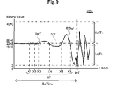
- FIG. 9 is a graph showing an example of the swing start time SwT specified by the processing of the arithmetic circuit 300c.
- the vertical axis indicates signal output.
- the horizontal axis indicates time.
- FIG. 10 is a flow chart showing the processing executed by the processing device 30c.
- the processing device 30c differs from the processing device 30 in that the method of specifying the swing start time SwT is different.
- the processing device 30c includes an arithmetic circuit 300c.
- the arithmetic circuit 300c specifies the swing start time SwT by a method different from that of the arithmetic circuit 300.
- FIG. hereinafter, in the configuration of the processing device 30c, the same configurations as those of the processing device 30 are denoted by the same reference numerals, and descriptions thereof are omitted.
- the arithmetic circuit 300c identifies the swing start time SwT by identifying the time when the first signal DSig1 crosses the reference value SiV.
- the crossing of the first signal DSig1 with the reference value SiV specifically means that the value of the first signal DSig1 changes from being above the reference value SiV to being below the reference value SiV, or is changed from being below the reference value SiV to being above the reference value SiV.
- the time when the value of the first signal DSig1 changes from being above the reference value SiV to being below the reference value SiV, or when the value of the first signal DSig1 changes from being below the reference value SiV to being above the reference value SiV. Define the time as cross time XT.
- the arithmetic circuit 300c After the first determination step (after step S12 in FIG. 10), the arithmetic circuit 300c identifies one or more cross times XT in the first signal DSig1 acquired in the period BeTime before the impact time InT. A specific step is executed (Fig. 10 step S43). In the example shown in FIG. 9, the first signal DSig1 crosses the reference value SiV at times X1 to X6. In this case, arithmetic circuit 300c specifies times X1 to X6 as cross times XT. The times X6 to X1 are close to the impact time InT in this order.
- the arithmetic circuit 300c executes a second identification step of identifying the swing start time SwT based on the cross time XT closest to the impact time InT by the reference number among the one or more cross times XT.
- the fourth closest cross time XT to the impact time InT is time X3. Therefore, the arithmetic circuit 300c specifies the time X3 as the swing start time SwT.
- the arithmetic circuit 300c repeats the processes of steps S10 to S12, S43, and S44, as shown in FIG.
- the processing device 30c includes an arithmetic circuit 300c.
- the arithmetic circuit 300c determines the swing start time based on the first signal DSig1 acquired from the sensor 10 that detects the deformation of the striking member 1 during the swing. More specifically, the arithmetic circuit 300c executes the first determination step of determining the impact time InT when the value of the first signal DSig1 becomes equal to or greater than the first determination value 1stTh.
- the arithmetic circuit 300c executes a first identification step of identifying one or more cross times XT in the first signal DSig1 acquired in the period BeTime before the impact time InT.
- the arithmetic circuit 300c executes a second identification step of identifying the swing start time SwT based on the cross time XT that is closest to the impact time InT by the reference number among the one or more cross times XT.
- the processing device 30c identifies the swing start time SwT after identifying the impact time InT. The time when the greatest force is applied to the striking member 1 is the moment of impact.
- the processing device 30c specifies the swing start time SwT. Therefore, even if force is applied to the striking member 1 by an action other than swing, the possibility of the processing device 30c erroneously judging the swing action is low. Therefore, the processing device 30c can accurately detect the moment when the user starts swinging the striking member 1 .
- the processing device 30c includes an arithmetic circuit 300c.
- the arithmetic circuit 300c determines the swing start time based on the first signal DSig1 acquired from the sensor 10 that detects the deformation of the striking member 1 during the swing. More specifically, the arithmetic circuit 300c performs a first identification step of identifying one or more cross times XT in the first signal DSig1 acquired in the period BeTime before the impact time InT.
- the arithmetic circuit 300c executes a second identification step of identifying the swing start time SwT based on the cross time XT that is closest to the impact time InT by the reference number among the one or more cross times XT.
- the reference number is set as follows. The number of cross times XT that occur from the start of the swing until the user hits the object is set as the reference number.
- the swing start time SwT can be easily identified by back-calculating the cross time XT closest to the reference number from the impact time InT. Therefore, the processing device 30c can easily detect the moment when the user starts swinging the striking member 1 .
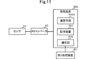
- FIG. 11 is a diagram showing an example of communication between the processing device 30d and the second processing device 40. As shown in FIG.
- the processing device 30d differs from the processing devices 30 and 30b in that it includes a communication unit 302 .
- the second processing device 40 is, for example, a swing analysis device.
- the swing analysis device analyzes the user's swing based on the first signal DSig1, for example.
- the processing device 30d is attached to the striking member 1 .
- the second processing device 40 is not attached to the striking member 1 . That is, the communication unit 302 performs communication between the processing device 30 d attached to the striking member 1 and the second processing device 40 not attached to the striking member 1 .
- Communication by the communication unit 302 is, for example, wireless communication.
- Wireless communication is, for example, communication using Bluetooth (registered trademark).
- the processing device 30d can accurately analyze the swing of the user. More specifically, the processing device 30 d has a communication unit 302 .
- the processing device 30d is attached to the striking member 1.
- the communication unit 302 transmits the swing start time SwT to the second processing device 40 different from the processing device 30d.
- the second processing device 40 can acquire the accurately specified swing start time SwT and impact time InT.
- the second processing device 40 can infer that the first signal DSig1 positioned between the swing start time SwT and the impact time InT is the first signal DSig1 generated when the user swings.
- the second processing device 40 is less likely to analyze the user's swing based on the first signal DSig1 generated by an action other than the swing.
- the processing device 30d allows the second processing device 40 to accurately analyze the user's swing.
- FIG. 12 is a diagram showing an example of a deletion step executed by the processing device 30e.
- the dot pattern indicates the period during which the first signal DSig1 is deleted.
- the processing device 30e differs from the processing devices 30 and 30b in that unnecessary signals are deleted from the acquired first signal DSig1. Specifically, the processing device 30e executes a deletion step of deleting the first signal DSig1 acquired at a time before the swing start time SwT.
- a storage device 301e (not shown) of the processing device 30e stores a program for executing the deletion step.
- the processing device 30e identifies the most recent period MPE that includes the swing start time SwT.
- the first signal DSig1 obtained at a time before the swing start time SwT is obtained at a time before the latest period MPE. Therefore, as shown in FIG. 12, the processing device 30e deletes the first signal DSig1 acquired in the period DeA earlier than the latest period MPE.
- the processing speed of the processing device 30e is improved. Specifically, the processing device 30e executes a deletion step of deleting the first signal DSig1 acquired at a time before the swing start time SwT. In this case, the first signal DSig1 other than the signal necessary for analyzing the user's swing is deleted. A case where the processing device 30e transmits the first signal DSig1 to the swing analysis device will be described below as an example. In this case, the processing device 30e converts the first signal DSig1 into data that can be transmitted to the swing analysis device. At this time, by executing the deletion step, the size of the data to be transmitted to the swing analysis device can be reduced. Therefore, it is possible to shorten the time until the data transmission to the swing analysis device in the processing device 30e is completed. That is, the processing speed of the processing device 30e is improved.
- the processing apparatuses 30 to 30e according to the present invention are not limited to the processing apparatuses 30 to 30e, and can be modified within the scope of the subject matter. Note that the configurations of the processing devices 30 to 30e may be combined arbitrarily.
- the processing devices 30 to 30c and 30e do not necessarily have to be attached to the striking member 1.
- a striking member communication section is attached to the striking member 1 .
- the striking member communication section may transmit the first signal DSig1 acquired from the sensor 10 to the processing devices 30 to 30c and 30e.
- the processing devices 30 to 30c and 30e may be terminals such as servers and smart phones. If the processing devices 30 to 30c, 30e are, for example, servers, smart phones, etc., the servers, smart phones, etc. execute the first determining step, the first identifying step, and the second identifying step.
- the hitting member 1 does not necessarily have to be a golf club.
- the striking member 1 may be a rod-shaped member such as a baseball bat, tennis racket, badminton racket, or the like.
- the striking member 1 may include at least one of a golf club, bat and racket.
- bats and rackets are striking members 1 that are easily deformed during a swing. That is, when the hitting member 1 is a bat or a racket, the processing device 30 can detect the moment when the user starts swinging the hitting member 1 with particularly high accuracy.
- the processing devices 30 to 30e determine the impact time InT based on the first difference value DV1 in the first determination step.
- the first difference value DV1 is the absolute value of the difference between the value of the first signal DSig1 and the reference value SiV. That is, the processing devices 30 to 30e can determine the swing start time SwT even when the waveform of the first signal DSig1 is inverted with respect to the reference value SiV. Therefore, the processing devices 30 to 30e can determine the swing start time SwT even when the user reverses the striking member 1 for each swing. For example, if the hitting member 1 is a bat, a racket, or the like, the user may invert the hitting member 1 with each swing.
- the processing devices 30 to 30e can accurately detect the swing start time SwT of each swing. Similarly, the processing devices 30 to 30e can accurately determine the swing start time SwT even when the user changes the direction in which the striking member 1 is swung for each swing.
- the processing device 30 identifies one or more periods PE in which the first difference value DV1 is less than the second determination value 2ndTh over the reference time.
- the processing device 30 may specify the period PE using the reference number of sampling instead of the reference time.
- the arithmetic circuit 300 identifies the number of times the first difference value DV1 has continuously fallen below the second determination value 2ndTh in the first identification step. Then, the arithmetic circuit 300 identifies a period during which the number of times the first difference value DV1 has been consecutively less than the second determination value 2ndTh exceeds the reference sampling number as the period PE.
- the reference sampling number is set in the processing device 30 .
- the reference sampling number is set to 5 times, 6 times, or the like in the processing device 30, for example. For example, when the processing device 30 sets the number of samplings to 5, the processing device 30 identifies a period during which the first difference value DV1 is less than the second determination value 2ndTh five consecutive times as the period PE.
- the hitting member 1 in the first embodiment or the second embodiment is a golf club. Therefore, the hit object in the first embodiment or the second embodiment is, for example, a golf ball.
- the communication by the communication unit 302 may be wired communication.
- the processing device 30d does not necessarily have to execute the deletion step based on the latest period MPE. For example, when the processing device 30d executes the third identifying step, the processing device 30d may delete the first signal DSig1 acquired at a time before the swing start time SwT identified by the third identifying step. good.
- the processing devices 30 to 30e do not necessarily have to input the signal AD-converted by the AD converter 20.
- the processing devices 30 to 30e may perform AD conversion processing.
- the processing units 30 to 30e receive analog signals from the sensor 10.
- FIG. The processors 30 to 30e AD-convert analog signals.
- the processing devices 30 to 30e specify the impact time InT and the swing start time SwT based on the first signal DSig1 obtained by AD conversion.
- the deformation direction of the striking member 1 is not limited to the vertical direction only.
- the striking member 1 may be deformed in a rotational direction around the center of the striking member 1 when viewed in the vertical direction. That is, the striking member 1 may be twisted in the direction of rotation.
- the sensor 10 may detect twist in the rotational direction.
- the value of the first signal DSig1 does not necessarily have to be the differential value of the deformation amount of the striking member 1.
- the value of the first signal DSig1 may be the amount of deformation of the striking member 1 .
- sensor 10 comprises a strain sensor.
- the value of the first signal DSig1 is the amount of deformation of the striking member 1
- the value of the first signal DSig1 may be the amount of deformation in a direction other than the lateral direction.
- the number of period PEs specified by the arithmetic circuit 300 is not limited to the two examples shown in FIG.
- the period PE specified by the arithmetic circuit 300 may be one. In this case, one period PE is the most recent period MPE. Also, the period PE specified by the arithmetic circuit 300 may be 3 or more. In this case, the arithmetic circuit 300 identifies the most recent period MPE closest to the impact time InT from among the three or more periods PE.
- the first determination value 1stTh does not necessarily have to be "2045".
- the arithmetic circuit 300 does not have to specify the swing start time SwT based on the first signal DSig1 converted into a bit value.
- the arithmetic circuit 300 may specify the swing start time SwT based on the first signal DSig1 converted to a voltage value of 0-3V.
- the first determination value 1stTh and the second determination value 2ndTh are set in the range of 0-3V.
- the arithmetic circuit 300 may identify the periods PE in order of proximity from the impact time InT. For example, after identifying the first period PE, the arithmetic circuit 300 may identify whether the period PE exists at a time before the first identified period PE. In this case, for example, the arithmetic circuit 300 identifies the period PE1 as the period PE. Then, when the period PE exists at the time before the period PE1, the arithmetic circuit 300 may specify the period PE that exists at the time before the period PE1 as the period PE2.
- the processing devices 30 to 30c and 30e do not necessarily have to include the communication unit 302.
- the communication unit 302 may transmit the swing start time SwT to a plurality of second processing devices 40 .
- the communication unit 302 does not necessarily have to transmit the swing start time SwT to the second processing device 40 .
- the arithmetic circuits 300 to 300e do not necessarily have to be CPUs.
- the arithmetic circuits 300 to 300e may be MPUs (Micro Processing Units), for example.
- the storage device 301 does not necessarily have to include a ROM.
- the storage device 301 may include, for example, flash memory instead of ROM.
- the charge amplifier 102 does not necessarily convert the charge into a voltage value within the range of 0.0V to 3.0V.
- Charge amplifier 102 may convert the charge to a voltage value in a range other than 0.0V to 3.0V.
- the charge amplifier 102 may, for example, convert the charge to a range of 0.0V to 1.5V, a range of 0.0V to 5.0V, or the like.
- the resolution of the AD converter 20 is not limited to only 12 bits.
- the resolution of the AD converter 20 may be a bit value other than 12 bits.
- the resolution of the AD converter 20 may be, for example, 10-bit value, 16-bit value, or the like.
- the processing devices 30 to 30e may execute the first determination step of determining the impact time InT based on one or more times when the first difference value DV1 becomes equal to or greater than the first determination value 1stTh.
- the processing devices 30e to 30e necessarily determine that the first difference value DV1 is the largest among one or more times when the first difference value DV1 becomes equal to or greater than the first determination value 1stTh. It is not necessary to determine the time when it becomes the impact time InT.
- the processing devices 30e to 30e may determine, for example, the time when the first difference value DV1 becomes equal to or greater than the first determination value 1stTh as the impact time InT.
- the processing devices 30e to 30e identify the time when the first difference value DV1 becomes equal to or greater than the first determination value 1stTh, the processing devices 30e to 30e determine that the first difference value DV1 is equal to or greater than the first determination value.
- the time at which it becomes 1stTh or more may be determined as the impact time InT. Also in this case, the processing devices 30 to 30e can accurately detect the moment when the user starts swinging the striking member 1.
- Striking member 10 Sensor 100: Piezoelectric film 101F: First electrode 101B: Second electrode 102: Charge amplifier 103: Voltage amplification circuit 20: AD converters 30 to 30e: Processing devices 300 to 300e: Arithmetic circuit 301: Storage device Sig1, DSig1: first signals PE, PE1, PE2: period MPE: latest period InT: impact time SwT: swing start time 1stTh: first judgment value 2ndTh: second judgment value DV1: first difference value XT: cross time
Abstract
This processing device is provided with an arithmetic circuit for determining a swing start time on the basis of a first signal obtained from a sensor that is attached to a striking member for, when being swung, hitting an object-to-be-struck, and that is for detecting deformation of the striking member when being swung. The processing device defines, as a first difference value, the absolute value of the difference between a reference value and the value of the first signal. The arithmetic circuit executes: a first determination step for determining an impact time on the basis of one or more times at which the first difference value has become equal to or greater than a first determination value; a first identification step for identifying, in the first signal acquired at a time prior to the impact time, a most recent period that is closest to the impact time, from among one or more periods where the first difference value remained lower than a second determination value over a reference duration; and a second identification step for identifying a swing start time, on the basis of the most recent period.
Description
本発明は、ユーザがゴルフクラブ等の打撃部材を振り始める瞬間を検知する処理装置に関する。
The present invention relates to a processing device that detects the moment when a user starts swinging a hitting member such as a golf club.
従来、ユーザによるゴルフクラブのスイングを解析する発明として、特許文献1に記載のスイング解析装置が知られている。特許文献1に記載のスイング解析装置において、ゴルフクラブのシャフトにセンサが取り付けられている。スイング解析装置は、センサから取得した信号を基に、ユーザのスイングを解析する。
Conventionally, a swing analysis device described in Patent Document 1 is known as an invention for analyzing a swing of a golf club by a user. In the swing analysis device disclosed in Patent Document 1, a sensor is attached to the shaft of the golf club. The swing analysis device analyzes the user's swing based on the signal acquired from the sensor.
特許文献1に記載のスイング解析装置において、ユーザがゴルフクラブ等の打撃部材を振り始める瞬間を精度よく特定することが望まれている。
In the swing analysis device described in Patent Document 1, it is desired to accurately identify the moment when the user starts swinging a hitting member such as a golf club.
本発明の目的は、ユーザが打撃部材を振り始める瞬間を精度よく特定する処理装置を提供することである。
An object of the present invention is to provide a processing device that accurately identifies the moment when the user starts swinging the striking member.
本願発明者は、ユーザが打撃部材を振り始める瞬間を精度よく特定する手法として、取得した信号が判定値を超えた時刻をスイング開始時刻と特定する手法について検討した。この場合、判定値は、スイングによって発生する信号の値に基づいて設定される。そして、処理装置は、センサから得られた信号の値が判定値を超えた時刻を、スイング開始時刻として検知する。
The inventor of the present application has studied a method of identifying the time when the acquired signal exceeds the judgment value as the swing start time as a method of accurately identifying the moment when the user starts swinging the striking member. In this case, the determination value is set based on the value of the signal generated by the swing. Then, the processing device detects the time when the value of the signal obtained from the sensor exceeds the judgment value as the swing start time.
しかし、本願発明者は、ユーザによるスイング以外の動作でも打撃部材に衝撃が加わる可能性があることに気が付いた。スイング以外の動作とは、例えば、ユーザが誤って打撃部材を倒してしまう動作である。この場合、スイングによって発生する力と同程度の力が打撃部材に加わる可能性があることに、本願発明者は気が付いた。結果、処理装置が、スイング以外の動作をスイング開始時として誤検知する可能性があることに、本願発明者は気が付いた。
However, the inventor of the present application has noticed that the impact may be applied to the striking member by actions other than swinging by the user. Actions other than swinging are, for example, actions in which the user erroneously knocks down the striking member. In this case, the inventor of the present application has noticed that there is a possibility that a force of the same degree as the force generated by the swing may be applied to the striking member. As a result, the inventor of the present application has noticed that the processing device may erroneously detect a motion other than the swing as the start of the swing.
そこで、本願発明者は、打撃部材の使用状況を考察した。考察の結果、本願発明者は、打撃部材に最も強い衝撃が加わる瞬間が、打撃部材と被打撃物とが衝突するインパクトの瞬間であることに気が付いた。すなわち、本願発明者は、インパクトの瞬間の衝撃よりも大きい衝撃は、打撃部材に加わらないことに気が付いた。結果、本願発明者は、インパクトの瞬間の信号値に基づいて第1判定値を設定した場合、処理装置が、インパクトの瞬間を誤検知する可能性は低いことに気が付いた。
Therefore, the inventor of the present application considered the usage of the striking member. As a result of consideration, the inventors of the present application have found that the moment when the striking member receives the strongest impact is the moment of impact when the striking member collides with the object to be struck. That is, the inventors of the present application have noticed that an impact greater than the impact at the moment of impact is not applied to the striking member. As a result, the inventors of the present application have found that when the first determination value is set based on the signal value at the moment of impact, the possibility of the processing device erroneously detecting the moment of impact is low.
そこで、本願発明者は、以下の手法によって、誤検知の可能性が低い処理装置が提供できると考えた。処理装置は、インパクト時刻を検知した場合、ユーザがスイングの動作をしたと判定する。そして、インパクト時刻よりも前に信号が取得された時刻の中からスイング開始時刻を特定する。
Therefore, the inventor of the present application thought that a processing device with a low possibility of false detection could be provided by the following method. When detecting the impact time, the processing device determines that the user has performed a swing motion. Then, the swing start time is specified from the times at which the signal was acquired before the impact time.
上記の検討を基に、本願発明者は、ユーザがゴルフクラブ等の打撃部材を振り始める瞬間を精度よく検知する手法を再度検討した。結果、本願発明者は、以下の発明に思い至った。
Based on the above studies, the inventor of the present application re-examined a technique for accurately detecting the moment when a user starts swinging a hitting member such as a golf club. As a result, the inventor of the present application came up with the following invention.
本発明の一形態に係る処理装置は、
スイングすることによって被打撃物を打撃するための打撃部材に取り付けられるセンサであって、前記打撃部材のスイング時の変形を検知するセンサから取得した第1信号を基にスイング開始時刻を判定する演算回路、
を備え、
基準値と前記第1信号の値との差の絶対値を第1差分値と定義し、
前記演算回路は、
前記第1差分値が第1判定値以上になった1以上の時刻に基づいてインパクト時刻を判定する第1判定ステップと、
前記インパクト時刻よりも前の時刻に取得された前記第1信号において、前記第1差分値が第2判定値を基準時間にわたって下回った1以上の期間の中から、前記インパクト時刻に最も近い最近期間を特定する第1特定ステップと、
前記最近期間に基づいてスイング開始時刻を特定する第2特定ステップと、
を実行する。 A processing apparatus according to one aspect of the present invention includes:
A calculation for determining a swing start time based on a first signal obtained from a sensor attached to a striking member for striking an object to be struck by swinging, the sensor detecting deformation of the striking member during swing. circuit,
with
defining the absolute value of the difference between the reference value and the value of the first signal as a first difference value;
The arithmetic circuit is
a first determination step of determining an impact time based on one or more times at which the first difference value becomes equal to or greater than a first determination value;
The most recent period closest to the impact time from among one or more periods in which the first difference value is below the second judgment value over a reference time in the first signal acquired at a time before the impact time. a first identifying step of identifying
a second identifying step of identifying a swing start time based on the latest period;
to run.
本発明の一形態に係る処理装置は、
スイングすることによって被打撃物を打撃するための打撃部材に取り付けられるセンサであって、前記打撃部材のスイング時の変形を検知するセンサから取得した第1信号を基にスイング開始時刻を判定する演算回路、
を備え、
前記第1信号の値が基準値を上回っている状態から下回っている状態へ変化する時刻、又は、前記第1信号の値が基準値を下回っている状態から上回っている状態へ変化する時刻をクロス時刻と定義し、
基準値と前記第1信号の値との差の絶対値を第1差分値と定義し、
前記演算回路は、
前記第1差分値が第1判定値以上になった1以上の時刻に基づいてインパクト時刻を判定する第1判定ステップと、
前記インパクト時刻よりも前の時刻に取得された第1信号において、1以上の前記クロス時刻を特定する第1特定ステップと、
1以上の前記クロス時刻のうち、前記インパクト時刻に基準数番目に近い前記クロス時刻に基づいてスイング開始時刻を特定する第2特定ステップと、
を実行する。 A processing apparatus according to one aspect of the present invention includes:
A calculation for determining a swing start time based on a first signal obtained from a sensor attached to a striking member for striking an object to be struck by swinging, the sensor detecting deformation of the striking member during swing. circuit,
with
The time at which the value of the first signal changes from being above the reference value to the state below it, or the time at which the value of the first signal changes from being below the reference value to being above the reference value. defined as cross time,
defining the absolute value of the difference between the reference value and the value of the first signal as a first difference value;
The arithmetic circuit is
a first determination step of determining an impact time based on one or more times at which the first difference value becomes equal to or greater than a first determination value;
a first identifying step of identifying one or more cross times in a first signal acquired at a time before the impact time;
a second specifying step of specifying a swing start time based on the cross time closest to the impact time by a reference number among the one or more cross times;
to run.
本明細書において、前後方向に延びる軸や部材は、必ずしも前後方向と平行である軸や部材だけを示すものではない。前後方向に延びる軸や部材とは、前後方向に対して±45°の範囲で傾斜している軸や部材のことである。同様に、上下方向に延びる軸や部材とは、上下方向に対して±45°の範囲で傾斜している軸や部材である。左右方向に延びる軸や部材とは、左右方向に対して±45°の範囲で傾斜している軸や部材である。
In this specification, shafts and members extending in the front-rear direction do not necessarily indicate only shafts and members parallel to the front-rear direction. A shaft or member extending in the front-rear direction is a shaft or member that is inclined within a range of ±45° with respect to the front-rear direction. Similarly, the shafts and members that extend in the vertical direction are shafts and members that are inclined within a range of ±45° with respect to the vertical direction. An axis or member extending in the left-right direction is an axis or member that is inclined within a range of ±45° with respect to the left-right direction.
以下では、第1部材及び第2部材とは、センサ装置が備えている構造物である。本明細書において、第1部材が第2部材の上に配置されるとは、以下の状態を指す。第1部材の少なくとも一部は、第2部材の真上に位置している。従って、上下方向に見て、第1部材は、第2部材と重なっている。この定義は、上下方向以外の方向にも適用される。
In the following, the first member and the second member are structures provided in the sensor device. In this specification, the first member being arranged on the second member refers to the following state. At least a portion of the first member is located directly above the second member. Therefore, when viewed in the vertical direction, the first member overlaps the second member. This definition also applies to directions other than the vertical direction.
本明細書において、第1部材が第2部材より上に配置されるとは、第1部材の少なくとも一部が第2部材の真上に位置している場合、及び、第1部材が第2部材の真上に位置せずに第1部材が第2部材の斜め上に位置している場合を含む。この場合、上下方向に見て、第1部材は、第2部材と重なっていなくてもよい。斜め上とは、例えば、左上、右上である。この定義は、上下方向以外の方向にも適用される。
In this specification, "the first member is arranged above the second member" means that at least part of the first member is positioned directly above the second member, and that the first member is positioned above the second member. This includes the case where the first member is positioned obliquely above the second member without being positioned directly above the member. In this case, the first member does not have to overlap the second member when viewed in the vertical direction. For example, diagonally upward means upper left and upper right. This definition also applies to directions other than the vertical direction.
本明細書において、特に断りのない場合には、第1部材の各部について以下のように定義する。第1部材の前部とは、第1部材の前半分を意味する。第1部材の後部とは、第1部材の後半分を意味する。第1部材の左部とは、第1部材の左半分を意味する。第1部材の右部とは、第1部材の右半分を意味する。第1部材の上部とは、第1部材の上半分を意味する。第1部材の下部とは、第1部材の下半分を意味する。第1部材の前端とは、第1部材の前方向の端を意味する。第1部材の後端とは、第1部材の後方向の端を意味する。第1部材の左端とは、第1部材の左方向の端を意味する。第1部材の右端とは、第1部材の右方向の端を意味する。第1部材の上端とは、第1部材の上方向の端を意味する。第1部材の下端とは、第1部材の下方向の端を意味する。第1部材の前端部とは、第1部材の前端及びその近傍を意味する。第1部材の後端部とは、第1部材の後端及びその近傍を意味する。第1部材の左端部とは、第1部材の左端及びその近傍を意味する。第1部材の右端部とは、第1部材の右端及びその近傍を意味する。第1部材の上端部とは、第1部材の上端及びその近傍を意味する。第1部材の下端部とは、第1部材の下端及びその近傍を意味する。
In this specification, unless otherwise specified, each part of the first member is defined as follows. By front of the first member is meant the front half of the first member. A rear portion of the first member means the rear half of the first member. The left portion of the first member means the left half of the first member. The right portion of the first member means the right half of the first member. By top of the first member is meant the top half of the first member. A lower portion of the first member means a lower half of the first member. The front end of the first member means the front end of the first member. The rear end of the first member means the rearward end of the first member. The left end of the first member means the left end of the first member. The right end of the first member means the right end of the first member. The upper end of the first member means the upper end of the first member. The lower end of the first member means the downward end of the first member. The front end of the first member means the front end of the first member and its vicinity. The rear end of the first member means the rear end of the first member and its vicinity. The left end of the first member means the left end of the first member and its vicinity. The right end of the first member means the right end of the first member and its vicinity. The upper end of the first member means the upper end of the first member and its vicinity. The lower end of the first member means the lower end of the first member and its vicinity.
本発明に係る処理装置は、ユーザが打撃部材を振り始める瞬間を精度よく特定することができる。
The processing device according to the present invention can accurately identify the moment when the user starts swinging the striking member.
(第1実施形態)
以下、第1実施形態に係る処理装置30について図面を参照しながら説明する。図1は、センサ10、ADコンバータ20及び処理装置30が取り付けられた打撃部材1の一例を示す図である。図2は、センサ10、ADコンバータ20及び処理装置30のブロック図である。図3は、センサ10の背面図及び左側面図である。図3に示す背面図において、第1電極101F及び第2電極101Bの記載は省略した。図4は、センサ10から処理装置30へ出力された第1信号DSig1の一例を示す図である。図4において、縦軸は、信号の出力を示す。図4において、横軸は、時間を示す。図5は、処理装置30が実行する処理を示すフローチャートである。 (First embodiment)
Hereinafter, theprocessing apparatus 30 according to the first embodiment will be described with reference to the drawings. FIG. 1 is a diagram showing an example of a striking member 1 to which a sensor 10, an AD converter 20 and a processing device 30 are attached. FIG. 2 is a block diagram of the sensor 10, AD converter 20 and processor 30. As shown in FIG. 3A and 3B are rear and left side views of the sensor 10. FIG. In the rear view shown in FIG. 3, description of the first electrode 101F and the second electrode 101B is omitted. FIG. 4 is a diagram showing an example of the first signal DSig1 output from the sensor 10 to the processing device 30. As shown in FIG. In FIG. 4, the vertical axis indicates signal output. In FIG. 4, the horizontal axis indicates time. FIG. 5 is a flow chart showing the processing executed by the processing device 30. As shown in FIG.
以下、第1実施形態に係る処理装置30について図面を参照しながら説明する。図1は、センサ10、ADコンバータ20及び処理装置30が取り付けられた打撃部材1の一例を示す図である。図2は、センサ10、ADコンバータ20及び処理装置30のブロック図である。図3は、センサ10の背面図及び左側面図である。図3に示す背面図において、第1電極101F及び第2電極101Bの記載は省略した。図4は、センサ10から処理装置30へ出力された第1信号DSig1の一例を示す図である。図4において、縦軸は、信号の出力を示す。図4において、横軸は、時間を示す。図5は、処理装置30が実行する処理を示すフローチャートである。 (First embodiment)
Hereinafter, the
本実施形態において、図1に示すように、上下方向、左右方向及び前後方向を定義する。具体的には、打撃部材1のシャフトが延びる方向を上下方向と定義する。打撃部材1のヘッドのフェースが向く方向を左方向と定義する。上下方向、左右方向に直交する方向を前後方向と定義する。ただし、上下方向、左右方向及び前後方向は、説明のために定義した方向である。従って、打撃部材1の実際の使用時における上下方向、左右方向及び前後方向は、図1に示す上下方向、左右方向及び前後方向と一致しなくてよい。
In this embodiment, as shown in FIG. 1, the up-down direction, the left-right direction, and the front-rear direction are defined. Specifically, the direction in which the shaft of the striking member 1 extends is defined as the vertical direction. The direction in which the face of the head of the striking member 1 faces is defined as the left direction. A direction orthogonal to the up-down direction and the left-right direction is defined as the front-rear direction. However, the up-down direction, the left-right direction, and the front-rear direction are directions defined for explanation. Therefore, the up-down direction, left-right direction and front-back direction of the striking member 1 during actual use need not coincide with the up-down direction, left-right direction and front-back direction shown in FIG.
打撃部材1は、被打撃物を打撃するための部材である。本実施形態では、打撃部材1は、ゴルフクラブである。従って、本実施形態では、打撃部材1は、上下方向に延びる棒形状を有している。ユーザは、打撃部材1をスイングすることによって被打撃物を打撃する。ユーザのスイング時に、打撃部材1は、変形をする。具体的には、ユーザが打撃部材1をスイングするときに慣性力や外力によって打撃部材1は変形する。打撃部材1は、例えば、スイングのときに左右方向に変形する。
The hitting member 1 is a member for hitting an object to be hit. In this embodiment, the striking member 1 is a golf club. Therefore, in this embodiment, the striking member 1 has a bar shape extending in the vertical direction. A user hits an object to be hit by swinging the hitting member 1 . When the user swings, the striking member 1 deforms. Specifically, when the user swings the hitting member 1, the hitting member 1 is deformed by inertial force and external force. The striking member 1 deforms in the left-right direction during a swing, for example.
センサ10、ADコンバータ20及び処理装置30は、スイングすることによって、被打撃物を打撃するための打撃部材1に取り付けられる。図1に示すように、本実施形態において、打撃部材1には、センサ10、ADコンバータ20及び処理装置30が固定されている。
The sensor 10, the AD converter 20 and the processing device 30 are attached to the striking member 1 for striking the object by swinging. As shown in FIG. 1, in this embodiment, a sensor 10, an AD converter 20 and a processor 30 are fixed to the striking member 1. As shown in FIG.
センサ10は、打撃部材1のスイング時の変形を検知する。具体的には、センサ10は、打撃部材1の変形に応じた電荷を発生する。センサ10は、電荷を電圧信号である第1信号Sig1に変換する。従って、本実施形態では、第1信号Sig1の値は、打撃部材1の左右方向の変形量に応じた値である。また、打撃部材1は弾性変形をする。従って、打撃部材1の左右方向の変形量は、ユーザのスイング時に打撃部材1に加わった力に比例する。換言すれば、第1信号Sig1の値は、ユーザが打撃部材1をスイングしたときに加わった力を間接的に示している。これにより、第1信号Sig1の値からユーザが打撃部材1のスイングを開始した時刻を推測可能である。例えば、ユーザが、スイングを開始した直後は、打撃部材1の変形量が少ない。従って、スイング開始前後においてセンサ10が検知する第1信号Sig1の値は小さい。換言すれば、第1信号Sig1の値が小さい期間にユーザがスイングを開始した時刻が含まれると推測可能である。以下、ユーザが打撃部材1のスイングを開始した時刻をスイング開始時刻SwTと称する。
The sensor 10 detects deformation of the striking member 1 during swing. Specifically, the sensor 10 generates an electric charge according to the deformation of the striking member 1 . The sensor 10 converts the charge into a first signal Sig1, which is a voltage signal. Therefore, in this embodiment, the value of the first signal Sig1 is a value corresponding to the deformation amount of the striking member 1 in the left-right direction. Also, the striking member 1 is elastically deformed. Therefore, the deformation amount of the hitting member 1 in the left-right direction is proportional to the force applied to the hitting member 1 when the user swings. In other words, the value of the first signal Sig1 indirectly indicates the force applied when the user swings the striking member 1 . As a result, the time at which the user started swinging the striking member 1 can be estimated from the value of the first signal Sig1. For example, the amount of deformation of the hitting member 1 is small immediately after the user starts swinging. Therefore, the value of the first signal Sig1 detected by the sensor 10 is small before and after the start of the swing. In other words, it can be inferred that the period when the value of the first signal Sig1 is small includes the time when the user starts swinging. Hereinafter, the time when the user starts swinging the striking member 1 is referred to as swing start time SwT.
同様にして、第1信号Sig1の値から打撃部材1が被打撃物をインパクトした時刻を推測可能である。例えば、ユーザが打撃部材1によって被打撃物を打撃する瞬間は、打撃部材1の変形量が大きい。従って、センサ10が検知する第1信号Sig1の値が大きい。換言すれば、センサ10が検知した第1信号Sig1の値が大きい期間に打撃部材1が被打撃物をインパクトした時刻が含まれると推測可能である。以下、打撃部材1が、被打撃物を打撃した時刻をインパクト時刻InTと称する。
Similarly, it is possible to estimate the time at which the striking member 1 impacts the object to be struck from the value of the first signal Sig1. For example, at the moment when the user hits an object to be hit with the hitting member 1, the amount of deformation of the hitting member 1 is large. Therefore, the value of the first signal Sig1 detected by the sensor 10 is large. In other words, it can be inferred that the period when the value of the first signal Sig1 detected by the sensor 10 is large includes the time when the striking member 1 impacts the object to be struck. Hereinafter, the time at which the hitting member 1 hits the object to be hit will be referred to as impact time InT.
以下、センサ10の構造を説明する。センサ10は、圧力を検知する圧電センサである。センサ10は、図3に示すように、圧電フィルム100、第1電極101F、第2電極101B、チャージアンプ102及び電圧増幅回路103を備えている。圧電フィルム100は、シート形状を有している。従って、圧電フィルム100は、図3に示すように、第1主面F1及び第2主面F2を有している。圧電フィルム100の上下方向の長さは、圧電フィルム100の左右方向の長さより長い。本実施形態では、圧電フィルム100は、前後方向に見て、上下方向に延びる長辺を有する長方形状を有している。圧電フィルム100は、圧電フィルム100の変形量に応じた電荷を発生する。本実施形態では、圧電フィルム100は、PLAフィルムである。以下、圧電フィルム100についてより詳細に説明する。
The structure of the sensor 10 will be described below. The sensor 10 is a piezoelectric sensor that detects pressure. The sensor 10 includes a piezoelectric film 100, a first electrode 101F, a second electrode 101B, a charge amplifier 102 and a voltage amplifier circuit 103, as shown in FIG. The piezoelectric film 100 has a sheet shape. Therefore, the piezoelectric film 100 has a first main surface F1 and a second main surface F2, as shown in FIG. The vertical length of the piezoelectric film 100 is longer than the horizontal length of the piezoelectric film 100 . In this embodiment, the piezoelectric film 100 has a rectangular shape with long sides extending in the vertical direction when viewed in the front-rear direction. The piezoelectric film 100 generates electric charges according to the amount of deformation of the piezoelectric film 100 . In this embodiment, the piezoelectric film 100 is a PLA film. The piezoelectric film 100 will be described in more detail below.
圧電フィルム100は、圧電フィルム100が上下方向に伸張されるように変形したときに発生する電荷の極性が、圧電フィルム100が左右方向に伸張されるように変形したときに発生する電荷の極性と逆となる特性を有している。具体的には、圧電フィルム100は、キラル高分子から形成されるフィルムである。キラル高分子とは、例えば、ポリ乳酸(PLA)、特にL型ポリ乳酸(PLLA)である。キラル高分子からなるPLLAは、主鎖が螺旋構造を有する。PLLAは、一軸延伸されて分子が配向する圧電性を有する。圧電フィルム100は、d14の圧電定数を有している。圧電フィルム100の一軸延伸方向(配向方向)は、上下方向及び左右方向のそれぞれに対して45度の角度を形成している。この45度は、例えば、45度±10度程度を含む角度を含む。これにより、圧電フィルム100は、圧電フィルム100が上下方向に伸張されるように変形すること又は上下方向に伸張されるように変形することにより、電荷を発生する。圧電フィルム100は、例えば、上下方向に伸張されるように変形すると正の電荷を発生する。圧電フィルム100は、例えば、左右方向に伸張されるように変形すると負の電荷を発生する。電荷の大きさは、伸張又は圧縮による圧電フィルム100の変形量に依存する。電荷の大きさは、伸張又は圧縮による圧電フィルム100の変形量の微分値に比例する。
In the piezoelectric film 100, the polarity of the charge generated when the piezoelectric film 100 is stretched in the vertical direction is the same as the polarity of the charge generated when the piezoelectric film 100 is stretched in the horizontal direction. It has the opposite characteristics. Specifically, piezoelectric film 100 is a film formed from a chiral polymer. A chiral polymer is, for example, polylactic acid (PLA), particularly L-type polylactic acid (PLLA). A PLLA composed of a chiral polymer has a helical structure in its main chain. PLLA is uniaxially stretched and has piezoelectricity in which the molecules are oriented. The piezoelectric film 100 has a piezoelectric constant of d14. The uniaxial stretching direction (orientation direction) of the piezoelectric film 100 forms an angle of 45 degrees with respect to each of the vertical direction and the horizontal direction. This 45 degrees includes angles including, for example, about 45 degrees±10 degrees. Accordingly, the piezoelectric film 100 generates an electric charge by being deformed such that the piezoelectric film 100 is stretched in the vertical direction or deformed by being stretched in the vertical direction. The piezoelectric film 100 generates a positive electric charge when it is deformed, for example, by being elongated in the vertical direction. For example, the piezoelectric film 100 generates negative charges when deformed so as to be elongated in the left-right direction. The magnitude of the charge depends on the amount of deformation of the piezoelectric film 100 due to stretching or compression. The magnitude of the charge is proportional to the differential value of the amount of deformation of the piezoelectric film 100 due to extension or compression.
第1電極101Fは、信号電極である。第1電極101Fは、第1主面F1に設けられている。第1電極101Fは、第1主面F1を覆っている。第1電極101Fは、例えば、ITO(酸化インジウムスズ)、ZnO(酸化亜鉛)等の有機電極、蒸着、メッキによる金属皮膜、銀ペーストによる印刷電極膜である。
The first electrode 101F is a signal electrode. The first electrode 101F is provided on the first main surface F1. The first electrode 101F covers the first main surface F1. The first electrode 101F is, for example, an organic electrode such as ITO (indium tin oxide) or ZnO (zinc oxide), a metal film by vapor deposition or plating, or a printed electrode film by silver paste.
第2電極101Bは、グランド電極である。第2電極101Bは、グランド電位に接続される。第2電極101Bは、第2主面F2に設けられている。これにより、圧電フィルム100は、第1電極101Fと第2電極101Bとの間に位置している。第2電極101Bは、第2主面F2を覆っている。第2電極101Bは、例えば、ITO(酸化インジウムスズ)、ZnO(酸化亜鉛)等の有機電極、蒸着、メッキによる金属皮膜、銀ペーストによる印刷電極膜である。
The second electrode 101B is a ground electrode. The second electrode 101B is connected to ground potential. The second electrode 101B is provided on the second main surface F2. Thereby, the piezoelectric film 100 is positioned between the first electrode 101F and the second electrode 101B. The second electrode 101B covers the second main surface F2. The second electrode 101B is, for example, an organic electrode such as ITO (indium tin oxide) or ZnO (zinc oxide), a metal film by vapor deposition or plating, or a printed electrode film by silver paste.
このようなセンサ10は、図示しない接着層を介して、打撃部材1に固定される。具体的には、接着層は、打撃部材1と第1電極101Fとを固定する。これにより、例えば、打撃部材1が左右方向に曲がるとき、打撃部材1が上下方向に伸び縮みする。従って、圧電フィルム100が上下方向に伸縮する。その結果、圧電フィルム100が電荷を発生する。すなわち、本実施形態では、打撃部材1が右方向に曲がった場合、圧電フィルム100は、負の電荷を発生する。また、本実施形態では、打撃部材1が左方向に曲がった場合、圧電フィルム100は、正の電荷を発生する。
Such a sensor 10 is fixed to the striking member 1 via an adhesive layer (not shown). Specifically, the adhesive layer fixes the striking member 1 and the first electrode 101F. Thereby, for example, when the striking member 1 bends in the horizontal direction, the striking member 1 expands and contracts in the vertical direction. Therefore, the piezoelectric film 100 expands and contracts in the vertical direction. As a result, the piezoelectric film 100 generates an electric charge. That is, in this embodiment, the piezoelectric film 100 generates a negative charge when the striking member 1 is bent rightward. Moreover, in this embodiment, when the striking member 1 is bent leftward, the piezoelectric film 100 generates a positive charge.
チャージアンプ102は、圧電フィルム100が発生した電荷を電圧信号である第1信号Sig1に変換する。例えば、チャージアンプ102は、電荷を0.0V~3.0Vの範囲の電圧値に変換する。変換後、チャージアンプ102は、第1信号Sig1を電圧増幅回路103に出力する。電圧増幅回路103は、第1信号Sig1を増幅して、ADコンバータ20に出力する。
The charge amplifier 102 converts the charge generated by the piezoelectric film 100 into a first signal Sig1, which is a voltage signal. For example, charge amplifier 102 converts the charge to a voltage value in the range of 0.0V to 3.0V. After conversion, the charge amplifier 102 outputs the first signal Sig1 to the voltage amplifier circuit 103 . The voltage amplification circuit 103 amplifies the first signal Sig1 and outputs it to the AD converter 20 .
ADコンバータ20は、第1信号Sig1をAD変換する。これにより、ADコンバータ20は、第1信号Sig1をデジタル信号に変換する。具体的には、ADコンバータ20は、ADコンバータ20の分解能に応じて第1信号Sig1の変換を行う。例えば、ADコンバータ20の分解能が12bitである場合、ADコンバータ20は、図4に示すように、第1信号Sig1を4096段階のバイナリ値に変換する。以下、デジタル信号に変換された第1信号Sig1を第1信号DSig1と称す。また、ADコンバータ20は、基準電圧を取得する。ADコンバータ20は、基準電圧を基に第1信号DSig1の基準値SiVを設定する。例えば、図4に示すように、ADコンバータ20は、基準値SiVとして、バイナリ値=2048を設定する。そして、ADコンバータ20は、第1信号DSig1を処理装置30へ出力する。
The AD converter 20 AD-converts the first signal Sig1. Thereby, the AD converter 20 converts the first signal Sig1 into a digital signal. Specifically, the AD converter 20 converts the first signal Sig1 according to the resolution of the AD converter 20 . For example, when the resolution of the AD converter 20 is 12 bits, the AD converter 20 converts the first signal Sig1 into 4096 levels of binary values as shown in FIG. The first signal Sig1 converted into a digital signal is hereinafter referred to as a first signal DSig1. Also, the AD converter 20 acquires a reference voltage. The AD converter 20 sets the reference value SiV of the first signal DSig1 based on the reference voltage. For example, as shown in FIG. 4, the AD converter 20 sets the binary value=2048 as the reference value SiV. The AD converter 20 then outputs the first signal DSig1 to the processing device 30 .
処理装置30は、第1信号DSig1を基にユーザによる打撃部材1のスイング開始時刻SwTを判定する。具体的には、処理装置30は、図2に示すように、演算回路300及び記憶装置301を備える。記憶装置301は、スイング開始時刻SwTを判定する処理のプログラムを記憶する。記憶装置301は、例えば、ROM(Read Only Memory)及びRAM(Random Access Memory)を含んでいる。演算回路300は、ROMに記憶されたプログラムをRAMに読み出す。これにより、演算回路300は、スイング開始時刻SwTを判定する処理を行う。このような、演算回路300は、例えば、CPU(Central Processing Unit)等である。
The processing device 30 determines the swing start time SwT of the hitting member 1 by the user based on the first signal DSig1. Specifically, the processing device 30 includes an arithmetic circuit 300 and a storage device 301, as shown in FIG. The storage device 301 stores a program for determining the swing start time SwT. The storage device 301 includes, for example, ROM (Read Only Memory) and RAM (Random Access Memory). The arithmetic circuit 300 reads the program stored in the ROM to the RAM. Accordingly, the arithmetic circuit 300 performs processing for determining the swing start time SwT. Such an arithmetic circuit 300 is, for example, a CPU (Central Processing Unit).
以下、処理装置30におけるスイング開始時刻SwTの特定に係る処理の詳細を説明する。本処理は、処理装置30がセンサ10から第1信号DSig1を取得することにより開始される。具体的には、まず、演算回路300は、センサ10から第1信号DSig1を取得する(図5:ステップS10)。
Details of the processing related to specifying the swing start time SwT in the processing device 30 will be described below. This process starts when the processing device 30 acquires the first signal DSig1 from the sensor 10 . Specifically, first, the arithmetic circuit 300 acquires the first signal DSig1 from the sensor 10 ( FIG. 5 : step S10).
次に、演算回路300は、基準値SiVと第1信号DSig1の値との差の絶対値が第1判定値1stTh以上となる1以上の時刻の有無を判定する(図5:ステップS11)。まず、演算回路300は、基準値SiVと第1信号DSig1の値との差の絶対値を算出する。以下、第1信号DSig1の値が“3”である場合、且つ、基準値SiVが“2048”である場合を例に説明する。この場合、第1信号DSig1から基準値SiVの値を引いた値は、“-2045”である。従って、演算回路300は、差の絶対値を“2045”と算出する。以下、基準値SiVと第1信号DSig1の値との差の絶対値を第1差分値DV1と定義する。
Next, the arithmetic circuit 300 determines whether or not there is one or more times when the absolute value of the difference between the reference value SiV and the value of the first signal DSig1 is equal to or greater than the first determination value 1stTh ( FIG. 5 : step S11). First, the arithmetic circuit 300 calculates the absolute value of the difference between the reference value SiV and the value of the first signal DSig1. A case where the value of the first signal DSig1 is "3" and the reference value SiV is "2048" will be described below as an example. In this case, the value obtained by subtracting the reference value SiV from the first signal DSig1 is "-2045". Therefore, the arithmetic circuit 300 calculates the absolute value of the difference as "2045". Hereinafter, the absolute value of the difference between the reference value SiV and the value of the first signal DSig1 is defined as a first difference value DV1.
次に、演算回路300は、第1差分値DV1が第1判定値1stTh以上であるかを判定する。第1判定値1stThは、処理装置30に記憶される値である。以下、図4を例に説明する。図4において、第1信号DSig1が、“3”以下である時刻TTが存在する。このとき、基準値SiVは、“2048”である。従って、第1差分値DV1は、“2045”である。一方、図4において、第1判定値1stThは、“2045”である。従って、時刻TTにおいて第1差分値DV1は第1判定値1stTh以上である。結果、演算回路300は、時刻TTを基準値SiVと第1信号DSig1の値との差の絶対値が第1判定値1stTh以上になった時刻と判定する。以下、第1差分値DV1が、第1判定値1stTh以上になった時刻を第1時刻と称する。
Next, the arithmetic circuit 300 determines whether the first difference value DV1 is greater than or equal to the first determination value 1stTh. The first determination value 1stTh is a value stored in the processing device 30 . An example of FIG. 4 will be described below. In FIG. 4, there is a time TT when the first signal DSig1 is "3" or less. At this time, the reference value SiV is "2048". Therefore, the first difference value DV1 is "2045". On the other hand, in FIG. 4, the first determination value 1stTh is "2045". Therefore, at time TT, the first difference value DV1 is greater than or equal to the first determination value 1stTh. As a result, the arithmetic circuit 300 determines the time TT as the time when the absolute value of the difference between the reference value SiV and the value of the first signal DSig1 becomes equal to or greater than the first determination value 1stTh. Hereinafter, the time when the first difference value DV1 becomes equal to or greater than the first determination value 1stTh will be referred to as the first time.
演算回路300が、1以上の時刻において第1差分値DV1が第1判定値1stTh以上となる1以上の時刻がないと判定した場合(図5:ステップS11 No)、処理装置30は、ステップS10の前まで処理を戻す。
When the arithmetic circuit 300 determines that there is no time at which the first difference value DV1 is equal to or greater than the first determination value 1stTh at one time or more ( FIG. 5 : step S11 No), the processing device 30 performs step S10. Return processing to before .
演算回路300が、1以上の時刻において第1差分値DV1が第1判定値1stTh以上となる1以上の時刻があると判定した場合(図5:ステップS11 Yes)、演算回路300は、第1差分値DV1が第1判定値1stTh以上になった1以上の時刻の内の、第1差分値DV1が最も大きくなった時刻をインパクト時刻InTと判定する第1判定ステップを実行する(図5:ステップS12)。図4において、演算回路300は、時刻TTを第1時刻と判定している。演算回路300は、時刻TT以外の時刻を第1時刻として判定していない。従って、1以上の時刻の内の、第1差分値DV1が最も大きくなった時刻は、時刻TTである。結果、演算回路300は、時刻TTを、インパクト時刻InTと判定する。
When the arithmetic circuit 300 determines that there is one or more times at which the first difference value DV1 is equal to or greater than the first judgment value 1stTh (FIG. 5: step S11 Yes), the arithmetic circuit 300 performs the first A first determination step of determining the time at which the first difference value DV1 becomes the largest among the one or more times at which the difference value DV1 becomes equal to or greater than the first determination value 1stTh as the impact time InT is executed (FIG. 5: step S12). In FIG. 4, the arithmetic circuit 300 determines the time TT as the first time. The arithmetic circuit 300 does not determine a time other than the time TT as the first time. Therefore, the time at which the first difference value DV1 becomes the largest among the one or more times is the time TT. As a result, the arithmetic circuit 300 determines the time TT as the impact time InT.
次に、演算回路300は、インパクト時刻InTよりも前の時刻BeTimeに取得された第1信号DSig1を調べることによって、スイング開始時刻SwTを特定する。具体的には、演算回路300は、インパクト時刻InTよりも前の時刻BeTimeに取得された第1信号DSig1において、第1差分値DV1が第2判定値2ndThを基準時間にわたって下回った1以上の期間PEの中から、インパクト時刻InTに最も近い最近期間MPEを特定する第1特定ステップを実行する(図5 ステップS13)。以下、第1特定ステップについて、詳細に説明する。
Next, the arithmetic circuit 300 identifies the swing start time SwT by examining the first signal DSig1 acquired at the time BeTime before the impact time InT. Specifically, in the first signal DSig1 acquired at the time BeTime prior to the impact time InT, the arithmetic circuit 300 detects one or more periods in which the first difference value DV1 is below the second determination value 2ndTh over the reference time. A first identification step is executed to identify the most recent period MPE closest to the impact time InT from among the PEs (step S13 in FIG. 5). The first identifying step will be described in detail below.
図4に示すように、演算回路300は、インパクト時刻InTよりも前の時刻BeTimeにおいて、第1差分値DV1が第2判定値2ndThを基準時間にわたって下回った1以上の期間PEを特定する。第2判定値2ndThの値は、第1判定値1stThの値よりも小さい。例えば、図4に示すように、処理装置30は、第2判定値2ndThを“200”と記憶する。この場合、第1差分値DV1が、“200”以下であれば、演算回路300は、第1差分値DV1が第2判定値2ndThを下回ったと判定する。基準時間は、例えば、0.2秒、0.3秒等と設定される。例えば、処理装置30において基準時間が、“0.2秒”と設定された場合、演算回路300は、第1差分値DV1が、第2判定値2ndThを0.2秒間下回った期間を期間PEとして特定する。演算回路300は、1以上の期間PEを特定する。具体的には、1つ目の期間PEを特定した後、演算回路300は、1つ目に特定した期間PEよりも後の時刻において期間PEが存在するかを特定する。例えば、図4に示すように、演算回路300は、期間PEとして期間PE1を特定する。図4に示す例において、期間PE1よりも後の時刻において期間PEが存在する。この場合、演算回路300は、期間PE1よりも後の時刻に存在した期間PEを期間PE2として特定する。
As shown in FIG. 4, the arithmetic circuit 300 identifies one or more periods PE in which the first difference value DV1 is below the second determination value 2ndTh over the reference time at the time BeTime before the impact time InT. The value of the second determination value 2ndTh is smaller than the value of the first determination value 1stTh. For example, as shown in FIG. 4, the processing device 30 stores the second determination value 2ndTh as "200". In this case, if the first difference value DV1 is "200" or less, the arithmetic circuit 300 determines that the first difference value DV1 is less than the second determination value 2ndTh. The reference time is set to 0.2 seconds, 0.3 seconds, or the like, for example. For example, when the reference time is set to “0.2 seconds” in the processing device 30, the arithmetic circuit 300 sets the period in which the first difference value DV1 is lower than the second determination value 2ndTh for 0.2 seconds as the period PE Identify as The arithmetic circuit 300 identifies one or more periods PE. Specifically, after identifying the first period PE, the arithmetic circuit 300 identifies whether the period PE exists at a time after the first identified period PE. For example, as shown in FIG. 4, the arithmetic circuit 300 identifies the period PE1 as the period PE. In the example shown in FIG. 4, the period PE exists at a time later than the period PE1. In this case, the arithmetic circuit 300 identifies the period PE that occurred after the period PE1 as the period PE2.
次に、演算回路300は、1以上の期間PEの中から、インパクト時刻InTに最も近い最近期間MPEを特定する。例えば、図4に示す例では、演算回路300は、期間PE1,PE2を特定している。図4に示すように、期間PE2は、期間PE1よりもインパクト時刻InTに近い。従って、演算回路300は、期間PE2を最近期間MPEと特定する。
Next, the arithmetic circuit 300 identifies the most recent period MPE closest to the impact time InT from among one or more periods PE. For example, in the example shown in FIG. 4, the arithmetic circuit 300 identifies periods PE1 and PE2. As shown in FIG. 4, the period PE2 is closer to the impact time InT than the period PE1. Therefore, the arithmetic circuit 300 identifies the period PE2 as the latest period MPE.
最後に、演算回路300は、最近期間MPEに基づいてスイング開始時刻SwTを特定する第2特定ステップを実行する(図5 ステップS14)。例えば、演算回路300は、最近期間MPEにおける最も前の時刻から最も後の時刻までをスイング開始時刻SwTとして特定する。具体的には、最近期間MPEにおいて最も前の時刻が5.0秒であり、且つ、最も後ろの時刻が5.2秒であった場合、演算回路300は、スイング開始時刻SwTを5.0秒~5.2秒の間と特定する。
Finally, the arithmetic circuit 300 executes a second identification step of identifying the swing start time SwT based on the latest period MPE (step S14 in FIG. 5). For example, the arithmetic circuit 300 identifies the time from the earliest time to the latest time in the latest period MPE as the swing start time SwT. Specifically, when the earliest time in the latest period MPE is 5.0 seconds and the latest time is 5.2 seconds, the arithmetic circuit 300 sets the swing start time SwT to 5.0 seconds. Specify between seconds and 5.2 seconds.
以上の処理によって、処理装置30は、スイング開始時刻SwTを特定する。演算回路300は、ステップS10からステップS14の処理を繰り返す。
Through the above processing, the processing device 30 identifies the swing start time SwT. The arithmetic circuit 300 repeats the processing from step S10 to step S14.
以下、処理装置30において、上記に示す処理が実行されたか否かを立証する方法について説明する。立証において、第1判定値1stTh、第2判定値2ndTh及び基準時間のそれぞれが特定された場合に、上記に示す処理が実行されたと考えることができる。以下、第1判定値1stTh、第2判定値2ndTh及び基準時間を特定する方法について詳細に説明する。まず、処理装置30は、第1信号DSig1を模した第2信号を入力する。第2信号は、インパクト期間と予備動作期間とを有する。インパクト期間は、予備動作期間よりも後の時刻に位置する期間である。
A method for verifying whether or not the processing shown above has been executed in the processing device 30 will be described below. In the proof, when each of the first determination value 1stTh, the second determination value 2ndTh, and the reference time is specified, it can be considered that the processing shown above has been executed. A method for specifying the first determination value 1stTh, the second determination value 2ndTh, and the reference time will be described in detail below. First, the processing device 30 inputs a second signal that simulates the first signal DSig1. The second signal has an impact period and a preliminary operation period. The impact period is a period located after the preliminary operation period.
最初に、第1判定値1stThを特定する方法について説明する。まず、予備動作期間における第2信号の値を基準値SiVに設定する。具体的には、図4に示した例のように、第2信号の値を、基準値SiVである“2048”等に設定する。次に、インパクト期間における第2信号の値を徐々に増加させる。そして、第2信号の値が所定の値以上となったときに、処理装置30が、スイング開始時刻SwTを特定する。具体的には、インパクト期間における第2信号の値を増加させた場合、第1差分値DV1が第1判定値1stTh以上の大きさとなる。このとき、予備動作期間における第2信号の値は基準値SiVである。すなわち、予備動作期間において第2信号の値は、基準時間にわたって第2判定値2ndTh以下となる。従って、処理装置30が、第1特定ステップ及び第2特定ステップを実行する条件を満たす。結果、処理装置30は、スイング開始時刻SwTを特定する。すなわち、処理装置30がスイング開始時刻SwTを特定したときの第2信号の値を特定することによって、第1判定値1stThが特定される。
First, a method for specifying the first judgment value 1stTh will be described. First, the value of the second signal in the preliminary operation period is set to the reference value SiV. Specifically, as in the example shown in FIG. 4, the value of the second signal is set to "2048" or the like, which is the reference value SiV. Next, the value of the second signal is gradually increased during the impact period. Then, when the value of the second signal reaches or exceeds a predetermined value, the processing device 30 specifies the swing start time SwT. Specifically, when the value of the second signal is increased during the impact period, the first difference value DV1 becomes greater than or equal to the first determination value 1stTh. At this time, the value of the second signal in the preliminary operation period is the reference value SiV. That is, during the preliminary operation period, the value of the second signal is equal to or less than the second determination value 2ndTh over the reference time. Therefore, the processing device 30 satisfies the conditions for executing the first identifying step and the second identifying step. As a result, the processing device 30 identifies the swing start time SwT. That is, the first determination value 1stTh is specified by specifying the value of the second signal when the processing device 30 specifies the swing start time SwT.
次に、第2判定値2ndThを特定する方法について説明する。第2判定値2ndThの特定は、第1判定値1stThの特定後に行われる。具体的には、第1判定値1stThの特定後、予備動作期間における第2信号の値の大きさを徐々に大きくする。そして、第2信号の値が所定の大きさ以上となったときに、処理装置30が、スイング開始時刻SwTを特定しなくなる。具体的には、予備動作期間における第2信号の値を小さくした場合、第1差分値DV1が、第2判定値2ndTh以上の大きさとなる。従って、処理装置30が第1特定ステップを実行する条件を満たさなくなる。結果、処理装置30は、スイング開始時刻SwTを特定しなくなる。すなわち、処理装置30がスイング開始時刻SwTを特定しなくなったときの第2信号の値を特定することによって、第2判定値2ndThが特定される。
Next, a method for specifying the second judgment value 2ndTh will be described. The second determination value 2ndTh is specified after the first determination value 1stTh is specified. Specifically, after specifying the first determination value 1stTh, the magnitude of the value of the second signal in the preliminary operation period is gradually increased. Then, when the value of the second signal reaches or exceeds a predetermined value, the processing device 30 stops specifying the swing start time SwT. Specifically, when the value of the second signal is decreased during the preliminary operation period, the first difference value DV1 becomes equal to or greater than the second determination value 2ndTh. Therefore, the processing device 30 no longer satisfies the conditions for executing the first specific step. As a result, the processing device 30 no longer specifies the swing start time SwT. That is, the second determination value 2ndTh is specified by specifying the value of the second signal when the processing device 30 no longer specifies the swing start time SwT.
最後に、基準時間を特定する方法について説明する。基準時間の特定は、第2判定値2ndThの特定後に行う。具体的には、予備動作期間における第2信号の値を第2判定値2ndThより小さくした状態で、予備動作期間において第2信号が出力される時間を徐々に短くする。以下、予備動作期間において第2信号が出力される時間を、第2時間と称する。そして、第2時間の長さが所定の長さ以下になった場合、処理装置30が、スイング開始時刻SwTを特定しなくなる。具体的には、第2時間を短くした場合、第2時間が、基準時間より短くなる。この場合、第1差分値DV1が、基準時間にわたって第2判定値2ndTh以下になるという条件を満たさなくなる。すなわち、処理装置30が第1特定ステップを実行する条件を満たさなくなる。結果、処理装置30は、スイング開始時刻SwTを特定しなくなる。すなわち、処理装置30がスイング開始時刻SwTを特定しなくなったときの、第2時間の長さを特定することによって、基準時間が特定される。
Finally, we will explain how to identify the reference time. The reference time is specified after the second determination value 2ndTh is specified. Specifically, the time during which the second signal is output during the preliminary operation period is gradually shortened while the value of the second signal during the preliminary operation period is made smaller than the second determination value 2ndTh. Hereinafter, the time during which the second signal is output during the preliminary operation period will be referred to as the second time. Then, when the length of the second time becomes equal to or less than the predetermined length, the processing device 30 stops specifying the swing start time SwT. Specifically, when the second time is shortened, the second time becomes shorter than the reference time. In this case, the condition that the first difference value DV1 is equal to or less than the second determination value 2ndTh over the reference time is no longer satisfied. That is, the processing device 30 no longer satisfies the conditions for executing the first specific step. As a result, the processing device 30 no longer specifies the swing start time SwT. That is, the reference time is specified by specifying the length of the second time when the processing device 30 no longer specifies the swing start time SwT.
以上に示す方法により、第1判定値1stTh、第2判定値2ndTh及び基準時間を特定できる。第1判定値1stTh、第2判定値2ndTh及び基準時間が特定された場合に、本実施形態に示す処理が実行されたと考えることができる。
By the method described above, the first judgment value 1stTh, the second judgment value 2ndTh, and the reference time can be specified. When the first determination value 1stTh, the second determination value 2ndTh, and the reference time are specified, it can be considered that the processing shown in this embodiment has been executed.
(第1実施形態の効果)
処理装置30によれば、ユーザが打撃部材1を振り始める瞬間を精度よく検知することができる。具体的には、処理装置30は、演算回路300を備える。演算回路300は、打撃部材1のスイング時の変形を検知するセンサ10から取得した第1信号Sig1を基にスイング開始時を判定する。より詳細には、演算回路300は、第1信号DSig1の値が第1判定値1stTh以上になった時刻をインパクト時刻InTと判定する第1判定ステップを実行する。次に、演算回路300は、インパクト時刻InTよりも前の時刻BeTimeに取得された第1信号DSig1において、第1信号DSig1の値が第2判定値2ndThを基準時間下回った1以上の期間PEの中から、インパクト時刻InTに最も近い最近期間MPEを特定する第1特定ステップを実行する。最後に、演算回路300は、最近期間MPEに基づいてスイング開始時刻SwTを特定する第2特定ステップを実行する。以下、取得した信号が判定値を超えた時刻をスイング開始時刻と特定する処理装置(以下、比較例1と称す)と、処理装置30とを比較して説明する。 (Effect of the first embodiment)
According to theprocessing device 30, the moment when the user starts swinging the hitting member 1 can be detected with high accuracy. Specifically, the processing device 30 includes an arithmetic circuit 300 . The arithmetic circuit 300 determines the swing start time based on the first signal Sig1 acquired from the sensor 10 that detects the deformation of the striking member 1 during the swing. More specifically, the arithmetic circuit 300 executes the first determination step of determining the time when the value of the first signal DSig1 becomes equal to or greater than the first determination value 1stTh as the impact time InT. Next, in the first signal DSig1 acquired at the time BeTime before the impact time InT, the arithmetic circuit 300 determines that the value of the first signal DSig1 is less than the second determination value 2ndTh for one or more periods PE. Among them, a first identification step is performed to identify the most recent period MPE closest to the impact time InT. Finally, arithmetic circuit 300 executes a second identification step of identifying swing start time SwT based on latest period MPE. Hereinafter, the processing device 30 will be compared with the processing device (hereinafter referred to as Comparative Example 1) that specifies the time when the acquired signal exceeds the determination value as the swing start time.
処理装置30によれば、ユーザが打撃部材1を振り始める瞬間を精度よく検知することができる。具体的には、処理装置30は、演算回路300を備える。演算回路300は、打撃部材1のスイング時の変形を検知するセンサ10から取得した第1信号Sig1を基にスイング開始時を判定する。より詳細には、演算回路300は、第1信号DSig1の値が第1判定値1stTh以上になった時刻をインパクト時刻InTと判定する第1判定ステップを実行する。次に、演算回路300は、インパクト時刻InTよりも前の時刻BeTimeに取得された第1信号DSig1において、第1信号DSig1の値が第2判定値2ndThを基準時間下回った1以上の期間PEの中から、インパクト時刻InTに最も近い最近期間MPEを特定する第1特定ステップを実行する。最後に、演算回路300は、最近期間MPEに基づいてスイング開始時刻SwTを特定する第2特定ステップを実行する。以下、取得した信号が判定値を超えた時刻をスイング開始時刻と特定する処理装置(以下、比較例1と称す)と、処理装置30とを比較して説明する。 (Effect of the first embodiment)
According to the
比較例1において、判定値は、スイング開始時において発生する信号の大きさに基づいて設定される。これにより、センサから得られた信号の値が判定値を超えた時刻を、スイング開始時刻として検知する。しかし、ユーザがスイング以外の動作でも打撃部材に衝撃を与える可能性がある。例えば、ユーザが誤って打撃部材を倒してしまう動作によって打撃部材に衝撃が加わる。この場合、スイングによって発生する力と同程度の力が打撃部材に加わる可能性がある。このとき、比較例1は、スイング以外の動作をスイング開始時として誤判定する可能性がある。従って、比較例1は、ユーザが打撃部材を振り始める瞬間を精度よく検知することができない。
In Comparative Example 1, the determination value is set based on the magnitude of the signal generated at the start of the swing. Thereby, the time when the value of the signal obtained from the sensor exceeds the judgment value is detected as the swing start time. However, there is a possibility that the user may give an impact to the striking member by actions other than the swing. For example, an impact is applied to the striking member by an action of the user accidentally knocking down the striking member. In this case, there is a possibility that a force of the same degree as the force generated by the swing will be applied to the striking member. At this time, in Comparative Example 1, there is a possibility that a motion other than the swing is erroneously determined as the start of the swing. Therefore, Comparative Example 1 cannot accurately detect the moment when the user starts swinging the striking member.
一方、処理装置30は、インパクト時刻InTを特定した後に、スイング開始時刻SwTを特定する。打撃部材1に最も大きな力が加わるときは、インパクトの瞬間である。従って、インパクトの大きさに合わせて第1判定値1stThを設定した場合、インパクト時刻InTが誤判定される可能性が低い。処理装置30は、インパクト時刻InTを判定した後に、スイング開始時刻SwTを特定する。従って、スイング以外の動作によって打撃部材1に力が加わった場合であっても、処理装置30が、スイング動作を誤判定する可能性が低い。従って、処理装置30は、ユーザが打撃部材1を振り始める瞬間を精度よく検知することができる。
On the other hand, the processing device 30 identifies the swing start time SwT after identifying the impact time InT. The time when the greatest force is applied to the striking member 1 is the moment of impact. Therefore, when the first determination value 1stTh is set according to the magnitude of the impact, there is a low possibility that the impact time InT will be erroneously determined. After determining the impact time InT, the processing device 30 specifies the swing start time SwT. Therefore, even if a force is applied to the striking member 1 by an action other than swing, the possibility of the processing device 30 erroneously judging the swing action is low. Therefore, the processing device 30 can accurately detect the moment when the user starts swinging the striking member 1 .
処理装置30によれば、処理装置30は、ユーザが打撃部材1を振り始める瞬間を精度よく検知することができる。より詳細には、演算回路300は、インパクト時刻InTよりも前の時刻BeTimeに取得された第1信号DSig1において、第1差分値DV1が第2判定値2ndThを基準時間下回った1以上の期間PEの中から、インパクト時刻InTに最も近い最近期間MPEを特定する第1特定ステップを実行する。また、演算回路300は、最近期間MPEに基づいてスイング開始時刻SwTを特定する第2特定ステップを実行する。スイング開始時刻SwTは、インパクト時刻InTよりも前に位置する。スイング開始時刻SwTにおいて、打撃部材1には大きな力が加わらない。従って、インパクト時刻InTよりも前の時刻において、第1差分値DV1が小さい期間を特定すれば、スイング開始時刻SwTを特定できる。但し、このとき、演算回路300は、インパクト時刻InTよりも前の時刻において、1以上の期間PEを特定する可能性がある。この場合、スイング開始時刻SwTよりも前の期間PEは、打撃部材1が静止していることによって第1差分値DV1が小さい期間である。すなわち、インパクト時刻InTから遠い期間PEは、スイング開始時刻SwTでない可能性が高い。従って、演算回路300が、インパクト時刻InTから最も近い最近期間MPEを特定する処理を行う。これにより、インパクト時刻InTから遠い期間PEが、スイング開始時刻SwTと特定されなくなる。従って、演算回路300が、スイング開始時刻SwTを誤特定する可能性が低減する。結果、処理装置30は、ユーザが打撃部材1を振り始める瞬間を精度よく検知することができる。
According to the processing device 30, the processing device 30 can accurately detect the moment when the user starts swinging the striking member 1. More specifically, in the first signal DSig1 acquired at the time BeTime before the impact time InT, the arithmetic circuit 300 determines that the first difference value DV1 is less than the second determination value 2ndTh for one or more periods PE , a first identification step of identifying the most recent period MPE closest to the impact time InT. Further, the arithmetic circuit 300 executes a second identifying step of identifying the swing start time SwT based on the most recent period MPE. The swing start time SwT is located before the impact time InT. No large force is applied to the striking member 1 at the swing start time SwT. Therefore, the swing start time SwT can be specified by specifying a period in which the first difference value DV1 is small at a time before the impact time InT. However, at this time, the arithmetic circuit 300 may identify one or more periods PE at a time before the impact time InT. In this case, the period PE before the swing start time SwT is a period in which the first difference value DV1 is small because the striking member 1 is stationary. That is, there is a high possibility that the period PE far from the impact time InT is not the swing start time SwT. Therefore, the arithmetic circuit 300 performs processing to identify the most recent period MPE closest to the impact time InT. As a result, the period PE far from the impact time InT is no longer identified as the swing start time SwT. Therefore, the possibility that the arithmetic circuit 300 erroneously specifies the swing start time SwT is reduced. As a result, the processing device 30 can accurately detect the moment when the user starts swinging the striking member 1 .
処理装置30によれば、ユーザが打撃部材1を振り始める瞬間を精度よく検知することができる。処理装置30は、打撃部材1の変形に応じてスイング開始時刻SwTを特定する。すなわち、打撃部材1が変形しやすい場合、処理装置30は、スイング開始時刻SwTを特定しやすい。ゴルフクラブは、スイング時に変形しやすい打撃部材1である。すなわち、打撃部材1がゴルフクラブである処理装置30は、ユーザが打撃部材1を振り始める瞬間を特に精度よく検知することができる。
According to the processing device 30, it is possible to accurately detect the moment when the user starts swinging the striking member 1. The processing device 30 specifies the swing start time SwT according to the deformation of the striking member 1 . That is, when the striking member 1 is likely to deform, the processing device 30 is likely to identify the swing start time SwT. A golf club is a hitting member 1 that is easily deformed during a swing. That is, the processing device 30 in which the hitting member 1 is a golf club can detect the moment when the user starts swinging the hitting member 1 with particularly high accuracy.
(第1実施形態の変形例1)
以下、第1実施形態の変形例1に係る処理装置30aについて図を参照して説明する。図6は、処理装置30aが実行する処理を示すフローチャートである。図7は、演算回路300aの実行する第3特定ステップの一例を示す図である。 (Modification 1 of the first embodiment)
Hereinafter, a processing device 30a according to Modification 1 of the first embodiment will be described with reference to the drawings. FIG. 6 is a flow chart showing the processing executed by the processing device 30a. FIG. 7 is a diagram showing an example of the third specifying step executed by thearithmetic circuit 300a.
以下、第1実施形態の変形例1に係る処理装置30aについて図を参照して説明する。図6は、処理装置30aが実行する処理を示すフローチャートである。図7は、演算回路300aの実行する第3特定ステップの一例を示す図である。 (Modification 1 of the first embodiment)
Hereinafter, a processing device 30a according to Modification 1 of the first embodiment will be described with reference to the drawings. FIG. 6 is a flow chart showing the processing executed by the processing device 30a. FIG. 7 is a diagram showing an example of the third specifying step executed by the
処理装置30aは、第2特定ステップの後に第3特定ステップを実行する点において、処理装置30と異なる。具体的には、処理装置30aは、演算回路300aを備える。演算回路300aは、第2特定ステップを実行した後(図6:ステップS14の後)、第3特定ステップを更に実行する(図6:ステップS21)。第3特定ステップは、インパクト時刻InTに最も近い最近期間MPEにおいてインパクト時刻InTから最も遠い時刻MTTをスイング開始時刻SwTとして特定するステップである。
The processing device 30a differs from the processing device 30 in that it executes the third identifying step after the second identifying step. Specifically, the processing device 30a includes an arithmetic circuit 300a. After executing the second identifying step (FIG. 6: after step S14), the arithmetic circuit 300a further executes the third identifying step (FIG. 6: step S21). The third identification step is a step of identifying the time MTT furthest from the impact time InT in the most recent period MPE closest to the impact time InT as the swing start time SwT.
例えば、図7に示すように、最近期間MPEにおいて演算回路300aが、第1信号DSig1の値を時刻T1~T6のそれぞれにおいて取得したとする。図7において、演算回路300aは、第1信号DSig1の値を、時刻T1,T2,T3,T4,T5,T6の順に取得している。この場合、時刻T1は、時刻T1~T6の中で最もインパクト時刻InTから遠い。換言すれば、最近期間MPEにおいて時刻T1は、インパクト時刻InTから最も遠い。この場合、演算回路300aは、時刻T1をスイング開始時刻SwTとして特定する。第3特定ステップを実行するプログラムは、処理装置30aが備える図示しない記憶装置301aに記憶される。
For example, as shown in FIG. 7, assume that the arithmetic circuit 300a acquires the value of the first signal DSig1 at each of times T1 to T6 in the latest period MPE. In FIG. 7, the arithmetic circuit 300a acquires the value of the first signal DSig1 in order of times T1, T2, T3, T4, T5, and T6. In this case, the time T1 is the farthest from the impact time InT among the times T1 to T6. In other words, the time T1 is the furthest from the impact time InT in the latest period MPE. In this case, the arithmetic circuit 300a specifies the time T1 as the swing start time SwT. A program for executing the third specifying step is stored in a storage device 301a (not shown) included in the processing device 30a.
(第1実施形態の変形例1の効果)
処理装置30aによれば、ユーザが打撃部材1を振り始める瞬間を更に精度よく検知することができる。より詳細には、演算回路300aは、インパクト時刻InTに最も近い最近期間MPEにおいてインパクト時刻InTから最も遠い時刻MTTをスイング開始時刻SwTとして特定する第3特定ステップを更に実行する。これにより、スイング開始時刻SwTを1つの時刻に絞り込むことができる。従って、ユーザが打撃部材1を振り始める瞬間を更に精度よく検知することができる。 (Effect of modification 1 of the first embodiment)
According to the processing device 30a, the moment when the user starts swinging the striking member 1 can be detected with even higher accuracy. More specifically, thearithmetic circuit 300a further executes a third identification step of identifying the time MTT furthest from the impact time InT in the most recent period MPE closest to the impact time InT as the swing start time SwT. Thereby, the swing start time SwT can be narrowed down to one time. Therefore, the moment when the user starts swinging the striking member 1 can be detected with higher accuracy.
処理装置30aによれば、ユーザが打撃部材1を振り始める瞬間を更に精度よく検知することができる。より詳細には、演算回路300aは、インパクト時刻InTに最も近い最近期間MPEにおいてインパクト時刻InTから最も遠い時刻MTTをスイング開始時刻SwTとして特定する第3特定ステップを更に実行する。これにより、スイング開始時刻SwTを1つの時刻に絞り込むことができる。従って、ユーザが打撃部材1を振り始める瞬間を更に精度よく検知することができる。 (Effect of modification 1 of the first embodiment)
According to the processing device 30a, the moment when the user starts swinging the striking member 1 can be detected with even higher accuracy. More specifically, the
処理装置30aによれば、ユーザのスイングを正確に解析できる。より詳細には、演算回路300aは、インパクト時刻InTに最も近い最近期間MPEにおいてインパクト時刻InTから最も遠い時刻MTTをスイング開始時刻SwTとして特定する第3特定ステップを更に実行する。これにより、スイング開始時刻SwTからインパクト時刻InTまでの時間を精度よく特定することができる。従って、ユーザがスイングを開始してから被打撃物を打撃するまでの間に発生した第1信号DSig1を正確に特定できる。結果、演算回路300aが、正確に特定した第1信号DSig1をユーザのスイングの解析に用いることによって、ユーザのスイングを正確に解析することができる。
The processing device 30a can accurately analyze the user's swing. More specifically, the arithmetic circuit 300a further executes a third identification step of identifying the time MTT furthest from the impact time InT in the most recent period MPE closest to the impact time InT as the swing start time SwT. This makes it possible to accurately identify the time from the swing start time SwT to the impact time InT. Therefore, it is possible to accurately identify the first signal DSig1 generated from the time the user starts swinging until the time the user hits the object. As a result, the arithmetic circuit 300a can accurately analyze the user's swing by using the accurately identified first signal DSig1 for analysis of the user's swing.
(第1実施形態の変形例2)
以下、第1実施形態の変形例2に係る処理装置30bについて図を参照して説明する。図8は、処理装置30bが実行する処理を示すフローチャートである。 (Modification 2 of the first embodiment)
Hereinafter, a processing device 30b according to Modification 2 of the first embodiment will be described with reference to the drawings. FIG. 8 is a flow chart showing the processing executed by the processing device 30b.
処理装置30bは、第1判定ステップと第1特定ステップの間に処理が追加された点で処理装置30と異なる。具体的には、処理装置30bは、図示しない演算回路300bを備える。演算回路300bは、インパクト時刻InTよりも前の時刻BeTimeに取得された第1信号DSig1の値が第2判定値2ndThを基準時間下回らなかった場合に、インパクト時刻InTに最も近い最近期間MPEを特定しない。
The processing device 30b differs from the processing device 30 in that processing is added between the first determination step and the first identification step. Specifically, the processing device 30b includes an arithmetic circuit 300b (not shown). If the value of the first signal DSig1 acquired at the time BeTime before the impact time InT does not fall below the second determination value 2ndTh for the reference time, the arithmetic circuit 300b identifies the most recent period MPE closest to the impact time InT. do not do.
具体的には、演算回路300bは、第1特定ステップを実行した後(図8:ステップS13の後)、第1信号DSig1の値が第2判定値2ndThを基準時間下回っているかを判定する(図8:ステップS31)。第1信号DSig1の値が第2判定値2ndThを基準時間下回っている場合(図8:ステップS31 Yes)、演算回路300bは、第1特定ステップを実行する(図8:ステップS13)。第1信号DSig1の値が第2判定値2ndThを基準時間下回っていない場合(図8:ステップS31 No)、演算回路300bは、ステップS10の前まで処理を戻す。
Specifically, after executing the first specifying step (FIG. 8: after step S13), the arithmetic circuit 300b determines whether the value of the first signal DSig1 is lower than the second determination value 2ndTh for the reference time ( FIG. 8: step S31). If the value of the first signal DSig1 is lower than the second determination value 2ndTh for the reference time (FIG. 8: step S31 Yes), the arithmetic circuit 300b executes the first specific step (FIG. 8: step S13). If the value of the first signal DSig1 is not less than the second determination value 2ndTh for the reference time ( FIG. 8 : step S31 No), the arithmetic circuit 300b returns the processing to before step S10.
(変形例2の効果)
処理装置30bによれば、処理装置30bは、処理装置30bの処理速度を向上できる。より詳細には、演算回路300bは、インパクト時刻InTよりも前の時刻BeTimeに取得された第1信号DSig1の値が第2判定値2ndThを基準時間下回らなかった場合に、インパクト時刻InTに最も近い最近期間MPEを特定しない。第1信号DSig1の値が第2判定値2ndThを基準時間下回らなかった場合は、処理装置30bがインパクト時刻InTを誤検知した可能性がある。この場合、処理装置30bは、第2特定ステップを実行しない。従って、処理装置30bは、誤検知により発生した処理を速やかに終了させることができる。すなわち、処理装置30bの処理速度が向上する。 (Effect of modification 2)
According to the processing device 30b, the processing device 30b can improve the processing speed of the processing device 30b. More specifically, if the value of the first signal DSig1 acquired at the time BeTime before the impact time InT does not fall below the second determination value 2ndTh for the reference time, the calculation circuit 300b determines the value closest to the impact time InT. Do not specify the recent period MPE. If the value of the first signal DSig1 has not fallen below the second determination value 2ndTh for the reference time, there is a possibility that the processing device 30b has erroneously detected the impact time InT. In this case, the processing device 30b does not execute the second identifying step. Therefore, the processing device 30b can quickly terminate the processing caused by the erroneous detection. That is, the processing speed of the processing device 30b is improved.
(第2実施形態)
以下、第2実施形態に係る処理装置30cについて図を参照して説明する。図9は、演算回路300cの処理によって特定されたスイング開始時刻SwTの一例を示すグラフである。図9において、縦軸は、信号の出力を示す。図9において、横軸は、時間を示す。図10は、処理装置30cが実行する処理を示すフローチャートである。 (Second embodiment)
Hereinafter, the processing device 30c according to the second embodiment will be described with reference to the drawings. FIG. 9 is a graph showing an example of the swing start time SwT specified by the processing of thearithmetic circuit 300c. In FIG. 9, the vertical axis indicates signal output. In FIG. 9, the horizontal axis indicates time. FIG. 10 is a flow chart showing the processing executed by the processing device 30c.
以下、第2実施形態に係る処理装置30cについて図を参照して説明する。図9は、演算回路300cの処理によって特定されたスイング開始時刻SwTの一例を示すグラフである。図9において、縦軸は、信号の出力を示す。図9において、横軸は、時間を示す。図10は、処理装置30cが実行する処理を示すフローチャートである。 (Second embodiment)
Hereinafter, the processing device 30c according to the second embodiment will be described with reference to the drawings. FIG. 9 is a graph showing an example of the swing start time SwT specified by the processing of the
処理装置30cは、スイング開始時刻SwTを特定する手法が異なる点で処理装置30と異なる。具体的には、処理装置30cは、演算回路300cを備える。そして、演算回路300cは、演算回路300と異なる手法によってスイング開始時刻SwTを特定する。以下、処理装置30cの構成において処理装置30と同じ構成は、同じ符号を付し、説明を省略する。
The processing device 30c differs from the processing device 30 in that the method of specifying the swing start time SwT is different. Specifically, the processing device 30c includes an arithmetic circuit 300c. Then, the arithmetic circuit 300c specifies the swing start time SwT by a method different from that of the arithmetic circuit 300. FIG. Hereinafter, in the configuration of the processing device 30c, the same configurations as those of the processing device 30 are denoted by the same reference numerals, and descriptions thereof are omitted.
演算回路300cは、第1信号DSig1が、基準値SiVと交差した時刻を特定することによってスイング開始時刻SwTを特定する。第1信号DSig1が、基準値SiVと交差するとは、具体的には、第1信号DSig1の値が基準値SiVを上回っている状態から下回っている状態へ変化すること、又は、第1信号DSig1の値が基準値SiVを下回っている状態から上回っている状態へ変化することである。以下、第1信号DSig1の値が基準値SiVを上回っている状態から下回る状態へ変化する時刻、又は、第1信号DSig1の値が基準値SiVを下回っている状態から上回っている状態へ変化する時刻をクロス時刻XTと定義する。
The arithmetic circuit 300c identifies the swing start time SwT by identifying the time when the first signal DSig1 crosses the reference value SiV. The crossing of the first signal DSig1 with the reference value SiV specifically means that the value of the first signal DSig1 changes from being above the reference value SiV to being below the reference value SiV, or is changed from being below the reference value SiV to being above the reference value SiV. Thereafter, the time when the value of the first signal DSig1 changes from being above the reference value SiV to being below the reference value SiV, or when the value of the first signal DSig1 changes from being below the reference value SiV to being above the reference value SiV. Define the time as cross time XT.
以下、演算回路300cの処理について詳細に説明する。第1判定ステップの後(図10 ステップS12の後)、演算回路300cは、インパクト時刻InTよりも前の期間BeTimeに取得された第1信号DSig1において、1以上のクロス時刻XTを特定する第1特定ステップを実行する(図10 ステップS43)。図9に示す例の場合、時刻X1~X6において、第1信号DSig1が、基準値SiVと交差している。この場合、演算回路300cは、時刻X1~X6をクロス時刻XTとして特定する。時刻X6~X1は、この順にインパクト時刻InTに近い。
The processing of the arithmetic circuit 300c will be described in detail below. After the first determination step (after step S12 in FIG. 10), the arithmetic circuit 300c identifies one or more cross times XT in the first signal DSig1 acquired in the period BeTime before the impact time InT. A specific step is executed (Fig. 10 step S43). In the example shown in FIG. 9, the first signal DSig1 crosses the reference value SiV at times X1 to X6. In this case, arithmetic circuit 300c specifies times X1 to X6 as cross times XT. The times X6 to X1 are close to the impact time InT in this order.
次に、演算回路300cは、1以上のクロス時刻XTのうち、インパクト時刻InTに基準数番目に近いクロス時刻XTに基づいてスイング開始時刻SwTを特定する第2特定ステップを実行する。以下、図9に示す処理装置30cにおいて基準数番目=4番目と設定されていた場合を例に説明する。この場合、図9に示すように、クロス時刻XTのうちインパクト時刻InTから4番目に近いクロス時刻XTは、時刻X3である。従って、演算回路300cは、時刻X3をスイング開始時刻SwTとして特定する。
Next, the arithmetic circuit 300c executes a second identification step of identifying the swing start time SwT based on the cross time XT closest to the impact time InT by the reference number among the one or more cross times XT. In the following, an example will be described in which the processing device 30c shown in FIG. 9 is set to the reference number=fourth. In this case, as shown in FIG. 9, the fourth closest cross time XT to the impact time InT is time X3. Therefore, the arithmetic circuit 300c specifies the time X3 as the swing start time SwT.
演算回路300cは、図10に示すように、ステップS10~S12,S43,S44の処理を繰り返す。
The arithmetic circuit 300c repeats the processes of steps S10 to S12, S43, and S44, as shown in FIG.
(第2実施形態の効果)
処理装置30cによれば、ユーザが打撃部材1を振り始める瞬間を精度よく検知することができる。具体的には、処理装置30cは、演算回路300cを備える。演算回路300cは、打撃部材1のスイング時の変形を検知するセンサ10から取得した第1信号DSig1を基にスイング開始時を判定する。より詳細には、演算回路300cは、第1信号DSig1の値が第1判定値1stTh以上になったときに、インパクト時刻InTと判定する第1判定ステップを実行する。演算回路300cは、インパクト時刻InTよりも前の期間BeTimeに取得された第1信号DSig1において、1以上のクロス時刻XTを特定する第1特定ステップを実行する。演算回路300cは、1以上のクロス時刻XTのうち、インパクト時刻InTに基準数番目に近いクロス時刻XTに基づいてスイング開始時刻SwTを特定する第2特定ステップを実行する。この場合、処理装置30cは、インパクト時刻InTを特定した後に、スイング開始時刻SwTを特定する。打撃部材1に最も大きな力が加わるときは、インパクトの瞬間である。従って、インパクトの大きさに合わせて第1判定値1stThを設定した場合、インパクト時刻InTが誤判定される可能性が低い。処理装置30cは、インパクト時刻InTを判定した後に、スイング開始時刻SwTを特定する。従って、スイング以外の動作によって打撃部材1に力が加わった場合であっても、処理装置30cが、スイング動作を誤判定する可能性が低い。従って、処理装置30cは、ユーザが打撃部材1を振り始める瞬間を精度よく検知することができる。 (Effect of Second Embodiment)
According to the processing device 30c, the moment when the user starts swinging the striking member 1 can be detected with high accuracy. Specifically, the processing device 30c includes anarithmetic circuit 300c. The arithmetic circuit 300c determines the swing start time based on the first signal DSig1 acquired from the sensor 10 that detects the deformation of the striking member 1 during the swing. More specifically, the arithmetic circuit 300c executes the first determination step of determining the impact time InT when the value of the first signal DSig1 becomes equal to or greater than the first determination value 1stTh. The arithmetic circuit 300c executes a first identification step of identifying one or more cross times XT in the first signal DSig1 acquired in the period BeTime before the impact time InT. The arithmetic circuit 300c executes a second identification step of identifying the swing start time SwT based on the cross time XT that is closest to the impact time InT by the reference number among the one or more cross times XT. In this case, the processing device 30c identifies the swing start time SwT after identifying the impact time InT. The time when the greatest force is applied to the striking member 1 is the moment of impact. Therefore, when the first determination value 1stTh is set according to the magnitude of the impact, there is a low possibility that the impact time InT will be erroneously determined. After determining the impact time InT, the processing device 30c specifies the swing start time SwT. Therefore, even if force is applied to the striking member 1 by an action other than swing, the possibility of the processing device 30c erroneously judging the swing action is low. Therefore, the processing device 30c can accurately detect the moment when the user starts swinging the striking member 1 .
処理装置30cによれば、ユーザが打撃部材1を振り始める瞬間を精度よく検知することができる。具体的には、処理装置30cは、演算回路300cを備える。演算回路300cは、打撃部材1のスイング時の変形を検知するセンサ10から取得した第1信号DSig1を基にスイング開始時を判定する。より詳細には、演算回路300cは、第1信号DSig1の値が第1判定値1stTh以上になったときに、インパクト時刻InTと判定する第1判定ステップを実行する。演算回路300cは、インパクト時刻InTよりも前の期間BeTimeに取得された第1信号DSig1において、1以上のクロス時刻XTを特定する第1特定ステップを実行する。演算回路300cは、1以上のクロス時刻XTのうち、インパクト時刻InTに基準数番目に近いクロス時刻XTに基づいてスイング開始時刻SwTを特定する第2特定ステップを実行する。この場合、処理装置30cは、インパクト時刻InTを特定した後に、スイング開始時刻SwTを特定する。打撃部材1に最も大きな力が加わるときは、インパクトの瞬間である。従って、インパクトの大きさに合わせて第1判定値1stThを設定した場合、インパクト時刻InTが誤判定される可能性が低い。処理装置30cは、インパクト時刻InTを判定した後に、スイング開始時刻SwTを特定する。従って、スイング以外の動作によって打撃部材1に力が加わった場合であっても、処理装置30cが、スイング動作を誤判定する可能性が低い。従って、処理装置30cは、ユーザが打撃部材1を振り始める瞬間を精度よく検知することができる。 (Effect of Second Embodiment)
According to the processing device 30c, the moment when the user starts swinging the striking member 1 can be detected with high accuracy. Specifically, the processing device 30c includes an
処理装置30cによれば、ユーザが打撃部材1を振り始める瞬間を容易に検知することができる。具体的には、処理装置30cは、演算回路300cを備える。演算回路300cは、打撃部材1のスイング時の変形を検知するセンサ10から取得した第1信号DSig1を基にスイング開始時を判定する。より詳細には、演算回路300cは、インパクト時刻InTよりも前の期間BeTimeに取得された第1信号DSig1において、1以上のクロス時刻XTを特定する第1特定ステップを実行する。演算回路300cは、1以上のクロス時刻XTのうち、インパクト時刻InTに基準数番目に近いクロス時刻XTに基づいてスイング開始時刻SwTを特定する第2特定ステップを実行する。例えば、処理装置30cにおいて、基準数番目は、以下の様に設定される。ユーザがスイングを開始してから被打撃物を打撃するまでの間に発生するクロス時刻XTの数を基準数番目として設定する。この場合、インパクト時刻InTから基準数番目に近いクロス時刻XTを逆算することによって、スイング開始時刻SwTを容易に特定することができる。従って、処理装置30cは、ユーザが打撃部材1を振り始める瞬間を容易に検知することができる。
According to the processing device 30c, it is possible to easily detect the moment when the user starts swinging the striking member 1. Specifically, the processing device 30c includes an arithmetic circuit 300c. The arithmetic circuit 300c determines the swing start time based on the first signal DSig1 acquired from the sensor 10 that detects the deformation of the striking member 1 during the swing. More specifically, the arithmetic circuit 300c performs a first identification step of identifying one or more cross times XT in the first signal DSig1 acquired in the period BeTime before the impact time InT. The arithmetic circuit 300c executes a second identification step of identifying the swing start time SwT based on the cross time XT that is closest to the impact time InT by the reference number among the one or more cross times XT. For example, in the processing device 30c, the reference number is set as follows. The number of cross times XT that occur from the start of the swing until the user hits the object is set as the reference number. In this case, the swing start time SwT can be easily identified by back-calculating the cross time XT closest to the reference number from the impact time InT. Therefore, the processing device 30c can easily detect the moment when the user starts swinging the striking member 1 .
(第1実施形態又は第2実施形態の変形例3)
以下、第1実施形態又は第2実施形態の変形例3に係る処理装置30dについて図を参照して説明する。図11は、処理装置30dと第2処理装置40との通信の一例を示す図である。 (Modification 3 of the first embodiment or the second embodiment)
Hereinafter, aprocessing device 30d according to Modification 3 of the first embodiment or the second embodiment will be described with reference to the drawings. FIG. 11 is a diagram showing an example of communication between the processing device 30d and the second processing device 40. As shown in FIG.
以下、第1実施形態又は第2実施形態の変形例3に係る処理装置30dについて図を参照して説明する。図11は、処理装置30dと第2処理装置40との通信の一例を示す図である。 (
Hereinafter, a
図11に示すように、処理装置30dは、通信部302を備える点で処理装置30,30bと異なる。通信部302は、図11に示すように、処理装置30dと異なる第2処理装置40にスイング開始時刻SwTを送信する。第2処理装置40とは、例えば、スイング解析装置である。スイング解析装置は、例えば、第1信号DSig1を基にユーザのスイングを解析する。変形例3において、処理装置30dは、打撃部材1に取り付けられている。第2処理装置40は、打撃部材1に取り付けられていない。すなわち、通信部302は、打撃部材1に取り付けられている処理装置30dと、打撃部材1に取り付けられていない第2処理装置40との通信を行う。通信部302による通信は、例えば、無線による通信である。無線による通信とは、例えばBluetooth(登録商標)を用いた通信等である。
As shown in FIG. 11 , the processing device 30d differs from the processing devices 30 and 30b in that it includes a communication unit 302 . The communication unit 302, as shown in FIG. 11, transmits the swing start time SwT to the second processing device 40 different from the processing device 30d. The second processing device 40 is, for example, a swing analysis device. The swing analysis device analyzes the user's swing based on the first signal DSig1, for example. In Modification 3, the processing device 30d is attached to the striking member 1 . The second processing device 40 is not attached to the striking member 1 . That is, the communication unit 302 performs communication between the processing device 30 d attached to the striking member 1 and the second processing device 40 not attached to the striking member 1 . Communication by the communication unit 302 is, for example, wireless communication. Wireless communication is, for example, communication using Bluetooth (registered trademark).
(変形例3の効果)
処理装置30dによれば、処理装置30dは、ユーザのスイングを正確に解析できる。より詳細には、処理装置30dは、通信部302を備えている。処理装置30dは、打撃部材1に取り付けられている。通信部302は、処理装置30dと異なる第2処理装置40にスイング開始時刻SwTを送信する。この場合、第2処理装置40は、正確に特定されたスイング開始時刻SwT及びインパクト時刻InTを取得することができる。そして、第2処理装置40は、スイング開始時刻SwTとインパクト時刻InTとの間に位置する第1信号DSig1を、ユーザのスイング時に発生した第1信号DSig1であると推測可能である。換言すれば、第2処理装置40が、スイング以外の動作により発生した第1信号DSig1を基にユーザのスイング解析を行う可能性が低減する。結果、処理装置30dによって、第2処理装置40は、ユーザのスイングを正確に解析できる。 (Effect of modification 3)
According to theprocessing device 30d, the processing device 30d can accurately analyze the swing of the user. More specifically, the processing device 30 d has a communication unit 302 . The processing device 30d is attached to the striking member 1. As shown in FIG. The communication unit 302 transmits the swing start time SwT to the second processing device 40 different from the processing device 30d. In this case, the second processing device 40 can acquire the accurately specified swing start time SwT and impact time InT. Then, the second processing device 40 can infer that the first signal DSig1 positioned between the swing start time SwT and the impact time InT is the first signal DSig1 generated when the user swings. In other words, the second processing device 40 is less likely to analyze the user's swing based on the first signal DSig1 generated by an action other than the swing. As a result, the processing device 30d allows the second processing device 40 to accurately analyze the user's swing.
処理装置30dによれば、処理装置30dは、ユーザのスイングを正確に解析できる。より詳細には、処理装置30dは、通信部302を備えている。処理装置30dは、打撃部材1に取り付けられている。通信部302は、処理装置30dと異なる第2処理装置40にスイング開始時刻SwTを送信する。この場合、第2処理装置40は、正確に特定されたスイング開始時刻SwT及びインパクト時刻InTを取得することができる。そして、第2処理装置40は、スイング開始時刻SwTとインパクト時刻InTとの間に位置する第1信号DSig1を、ユーザのスイング時に発生した第1信号DSig1であると推測可能である。換言すれば、第2処理装置40が、スイング以外の動作により発生した第1信号DSig1を基にユーザのスイング解析を行う可能性が低減する。結果、処理装置30dによって、第2処理装置40は、ユーザのスイングを正確に解析できる。 (Effect of modification 3)
According to the
(第1実施形態又は第2実施形態の変形例4)
以下、第1実施形態又は第2実施形態の変形例4に係る処理装置30eについて図を参照して説明する。図12は、処理装置30eが実行した削除ステップの一例を示す図である。図12において、ドットパターンは、第1信号DSig1が削除された期間を示す。 (Modification 4 of the first embodiment or the second embodiment)
Hereinafter, a processing device 30e according to Modification 4 of the first embodiment or the second embodiment will be described with reference to the drawings. FIG. 12 is a diagram showing an example of a deletion step executed by the processing device 30e. In FIG. 12, the dot pattern indicates the period during which the first signal DSig1 is deleted.
処理装置30eは、取得された第1信号DSig1において不要な信号を削除する点で処理装置30,30bと異なる。具体的には、処理装置30eは、スイング開始時刻SwTよりも前の時刻に取得された第1信号DSig1を削除する削除ステップを実行する。処理装置30eの記憶装置301e(図示せず)は、削除ステップを実行するプログラムを記憶する。
The processing device 30e differs from the processing devices 30 and 30b in that unnecessary signals are deleted from the acquired first signal DSig1. Specifically, the processing device 30e executes a deletion step of deleting the first signal DSig1 acquired at a time before the swing start time SwT. A storage device 301e (not shown) of the processing device 30e stores a program for executing the deletion step.
例えば、図12に示すように、処理装置30eは、スイング開始時刻SwTが含まれる最近期間MPEを特定する。この場合、スイング開始時刻SwTよりも前の時刻に取得された第1信号DSig1は、最近期間MPEよりも前の時刻に取得される。従って、処理装置30eは、図12に示すように、最近期間MPEよりも前の期間DeAに取得された第1信号DSig1を削除する。
For example, as shown in FIG. 12, the processing device 30e identifies the most recent period MPE that includes the swing start time SwT. In this case, the first signal DSig1 obtained at a time before the swing start time SwT is obtained at a time before the latest period MPE. Therefore, as shown in FIG. 12, the processing device 30e deletes the first signal DSig1 acquired in the period DeA earlier than the latest period MPE.
(変形例4の効果)
処理装置30eによれば、処理装置30eの処理速度が向上する。具体的には、処理装置30eは、スイング開始時刻SwTよりも前の時刻に取得された第1信号DSig1を削除する削除ステップを実行する。この場合、ユーザのスイングを解析するために必要な信号以外の第1信号DSig1は、削除される。以下、処理装置30eが、第1信号DSig1をスイング解析装置に送信する場合を例に説明する。この場合、処理装置30eは、第1信号DSig1をスイング解析装置へ送信可能なデータへ変換する。このとき、削除ステップを実行することによって、スイング解析装置へ送信するデータの大きさを小さくすることができる。従って、処理装置30eにおけるスイング解析装置へのデータの送信を完了させるまでの時間が短縮できる。すなわち、処理装置30eの処理速度が向上する。 (Effect of modification 4)
According to the processing device 30e, the processing speed of the processing device 30e is improved. Specifically, the processing device 30e executes a deletion step of deleting the first signal DSig1 acquired at a time before the swing start time SwT. In this case, the first signal DSig1 other than the signal necessary for analyzing the user's swing is deleted. A case where the processing device 30e transmits the first signal DSig1 to the swing analysis device will be described below as an example. In this case, the processing device 30e converts the first signal DSig1 into data that can be transmitted to the swing analysis device. At this time, by executing the deletion step, the size of the data to be transmitted to the swing analysis device can be reduced. Therefore, it is possible to shorten the time until the data transmission to the swing analysis device in the processing device 30e is completed. That is, the processing speed of the processing device 30e is improved.
(その他の実施形態)
本発明に係る処理装置30~30eは、処理装置30~30eに限らず、その要旨の範囲において変更可能である。なお、処理装置30~30eの構成を任意に組み合わせてもよい。 (Other embodiments)
The processing apparatuses 30 to 30e according to the present invention are not limited to theprocessing apparatuses 30 to 30e, and can be modified within the scope of the subject matter. Note that the configurations of the processing devices 30 to 30e may be combined arbitrarily.
本発明に係る処理装置30~30eは、処理装置30~30eに限らず、その要旨の範囲において変更可能である。なお、処理装置30~30eの構成を任意に組み合わせてもよい。 (Other embodiments)
The processing apparatuses 30 to 30e according to the present invention are not limited to the
なお、処理装置30~30c,30eは、必ずしも打撃部材1に取り付けられていなくてもよい。例えば、打撃部材1に打撃部材用通信部を取り付ける。そして、打撃部材用通信部が、センサ10から取得した第1信号DSig1を処理装置30~30c,30eに送信してもよい。この場合、処理装置30~30c,30eとは、例えば、サーバー、スマートホン等の端末であってもよい。処理装置30~30c,30eが、例えば、サーバー、スマートホン等である場合、サーバー、スマートホン等が、第1判定ステップ、第1特定ステップ及び第2特定ステップを実行する。
It should be noted that the processing devices 30 to 30c and 30e do not necessarily have to be attached to the striking member 1. For example, a striking member communication section is attached to the striking member 1 . Then, the striking member communication section may transmit the first signal DSig1 acquired from the sensor 10 to the processing devices 30 to 30c and 30e. In this case, the processing devices 30 to 30c and 30e may be terminals such as servers and smart phones. If the processing devices 30 to 30c, 30e are, for example, servers, smart phones, etc., the servers, smart phones, etc. execute the first determining step, the first identifying step, and the second identifying step.
なお、打撃部材1は、必ずしもゴルフクラブでなくてよい。打撃部材1は、野球のバットや、テニス,バドミントン等のラケット等の棒形状を有する部材であってもよい。換言すれば、打撃部材1は、ゴルフクラブ、バット及びラケットの少なくとも1つを含んでいてもよい。ゴルフクラブと同様にして、バット、ラケットは、スイング時に変形しやすい打撃部材1である。すなわち、打撃部材1がバット又はラケットである場合、処理装置30は、ユーザが打撃部材1を振り始める瞬間を特に精度よく検知することができる。
The hitting member 1 does not necessarily have to be a golf club. The striking member 1 may be a rod-shaped member such as a baseball bat, tennis racket, badminton racket, or the like. In other words, the striking member 1 may include at least one of a golf club, bat and racket. Like golf clubs, bats and rackets are striking members 1 that are easily deformed during a swing. That is, when the hitting member 1 is a bat or a racket, the processing device 30 can detect the moment when the user starts swinging the hitting member 1 with particularly high accuracy.
なお、処理装置30~30eは、第1判定ステップにおいて、第1差分値DV1を基にインパクト時刻InTを判定する。第1差分値DV1は、第1信号DSig1の値と基準値SiVとの差の絶対値である。すなわち、処理装置30~30eは、第1信号DSig1の波形が、基準値SiVに対して反転した場合でもスイング開始時刻SwTを判定できる。従って、処理装置30~30eは、ユーザがスイング毎に打撃部材1を反転させた場合でも、スイング開始時刻SwTを判定することができる。例えば、打撃部材1が、バット、ラケット等である場合、ユーザはスイング毎に、打撃部材1を反転させる可能性がある。この場合も、処理装置30~30eは、それぞれのスイングにおけるスイング開始時刻SwTを精度よく検知可能である。同様にして、処理装置30~30eは、ユーザがスイング毎に、打撃部材1をスイングする方向を変えた場合でも、スイング開始時刻SwTを精度よく判定することができる。
Note that the processing devices 30 to 30e determine the impact time InT based on the first difference value DV1 in the first determination step. The first difference value DV1 is the absolute value of the difference between the value of the first signal DSig1 and the reference value SiV. That is, the processing devices 30 to 30e can determine the swing start time SwT even when the waveform of the first signal DSig1 is inverted with respect to the reference value SiV. Therefore, the processing devices 30 to 30e can determine the swing start time SwT even when the user reverses the striking member 1 for each swing. For example, if the hitting member 1 is a bat, a racket, or the like, the user may invert the hitting member 1 with each swing. Also in this case, the processing devices 30 to 30e can accurately detect the swing start time SwT of each swing. Similarly, the processing devices 30 to 30e can accurately determine the swing start time SwT even when the user changes the direction in which the striking member 1 is swung for each swing.
なお、第1実施形態において処理装置30は、第1差分値DV1が第2判定値2ndThを基準時間にわたって下回った1以上の期間PEを特定する。しかし、処理装置30は、基準時間の代わりに基準サンプリング数を用いて期間PEを特定してもよい。この場合、演算回路300は、第1特定ステップにおいて第1差分値DV1が第2判定値2ndThを連続した下回った回数を特定する。そして、演算回路300は、第1差分値DV1が第2判定値2ndThを連続して下回った回数が基準サンプリング数を超えた期間を期間PEとして特定する。基準サンプリング数は、処理装置30に設定される。基準サンプリング数は、例えば、処理装置30において5回、6回等と設定される。例えば、処理装置30においてサンプリング数が5回と設定された場合、処理装置30は、第1差分値DV1が第2判定値2ndThを5回連続して下回った期間を期間PEとして特定する。
Note that in the first embodiment, the processing device 30 identifies one or more periods PE in which the first difference value DV1 is less than the second determination value 2ndTh over the reference time. However, the processing device 30 may specify the period PE using the reference number of sampling instead of the reference time. In this case, the arithmetic circuit 300 identifies the number of times the first difference value DV1 has continuously fallen below the second determination value 2ndTh in the first identification step. Then, the arithmetic circuit 300 identifies a period during which the number of times the first difference value DV1 has been consecutively less than the second determination value 2ndTh exceeds the reference sampling number as the period PE. The reference sampling number is set in the processing device 30 . The reference sampling number is set to 5 times, 6 times, or the like in the processing device 30, for example. For example, when the processing device 30 sets the number of samplings to 5, the processing device 30 identifies a period during which the first difference value DV1 is less than the second determination value 2ndTh five consecutive times as the period PE.
なお、第1実施形態又は第2実施形態において打撃部材1は、ゴルフクラブである。従って、第1実施形態又は第2実施形態における被打撃物は、例えば、ゴルフボールである。
It should be noted that the hitting member 1 in the first embodiment or the second embodiment is a golf club. Therefore, the hit object in the first embodiment or the second embodiment is, for example, a golf ball.
なお、通信部302による通信は有線による通信であってもよい。
The communication by the communication unit 302 may be wired communication.
なお、処理装置30dは、必ずしも最近期間MPEを基に削除ステップを実行しなくてもよい。例えば、処理装置30dが、第3特定ステップを実行する場合、処理装置30dは、第3特定ステップにより特定されたスイング開始時刻SwTより前の時刻に取得された第1信号DSig1を削除してもよい。
Note that the processing device 30d does not necessarily have to execute the deletion step based on the latest period MPE. For example, when the processing device 30d executes the third identifying step, the processing device 30d may delete the first signal DSig1 acquired at a time before the swing start time SwT identified by the third identifying step. good.
なお、処理装置30~30eが、必ずしも、ADコンバータ20によってAD変換された信号を入力しなくてもよい。例えば、処理装置30~30eが、AD変換処理を実行してもよい。この場合、処理装置30~30eは、センサ10からアナログ信号を入力する。処理装置30~30eは、アナログ信号をAD変換する。そして、処理装置30~30eは、AD変換によって得られた第1信号DSig1を基にインパクト時刻InT及びスイング開始時刻SwTを特定する。
It should be noted that the processing devices 30 to 30e do not necessarily have to input the signal AD-converted by the AD converter 20. For example, the processing devices 30 to 30e may perform AD conversion processing. In this case, the processing units 30 to 30e receive analog signals from the sensor 10. FIG. The processors 30 to 30e AD-convert analog signals. Then, the processing devices 30 to 30e specify the impact time InT and the swing start time SwT based on the first signal DSig1 obtained by AD conversion.
なお、打撃部材1の変形方向は、上下方向のみに限定されない。例えば、打撃部材1は、上下方向に見て、打撃部材1の中心を軸とした回転方向に変形する場合がある。すなわち、打撃部材1は回転方向にねじれる場合がある。この場合、センサ10は、回転方向のねじれを検知してもよい。
It should be noted that the deformation direction of the striking member 1 is not limited to the vertical direction only. For example, the striking member 1 may be deformed in a rotational direction around the center of the striking member 1 when viewed in the vertical direction. That is, the striking member 1 may be twisted in the direction of rotation. In this case, the sensor 10 may detect twist in the rotational direction.
なお、第1信号DSig1の値は、必ずしも打撃部材1の変形量の微分値でなくてもよい。第1信号DSig1の値は、打撃部材1の変形量であってもよい。この場合、センサ10は、歪センサを含む。
The value of the first signal DSig1 does not necessarily have to be the differential value of the deformation amount of the striking member 1. The value of the first signal DSig1 may be the amount of deformation of the striking member 1 . In this case, sensor 10 comprises a strain sensor.
なお、第1信号DSig1の値が、打撃部材1の変形量である場合、第1信号DSig1の値は、左右方向以外の方向の変形量であってもよい。
If the value of the first signal DSig1 is the amount of deformation of the striking member 1, the value of the first signal DSig1 may be the amount of deformation in a direction other than the lateral direction.
なお、演算回路300の特定する期間PEの数は、図4に示した2個の例に限定されない。演算回路300が特定した期間PEは1つであってもよい。この場合、1つの期間PEが最近期間MPEである。また、演算回路300の特定した期間PEは3以上であってもよい。この場合、演算回路300は、3以上の期間PEの中から最もインパクト時刻InTに近い最近期間MPEを特定する。
Note that the number of period PEs specified by the arithmetic circuit 300 is not limited to the two examples shown in FIG. The period PE specified by the arithmetic circuit 300 may be one. In this case, one period PE is the most recent period MPE. Also, the period PE specified by the arithmetic circuit 300 may be 3 or more. In this case, the arithmetic circuit 300 identifies the most recent period MPE closest to the impact time InT from among the three or more periods PE.
なお、第1判定値1stThは、必ずしも“2045”でなくてもよい。
Note that the first determination value 1stTh does not necessarily have to be "2045".
なお、第2判定値2ndThは、必ずしも“200”でなくてもよい。
Note that the second determination value 2ndTh does not necessarily have to be "200".
なお、演算回路300は、bit値に変換された第1信号DSig1を基にスイング開始時刻SwTを特定しなくてもよい。例えば、演算回路300は、0-3Vの電圧値に変換された第1信号DSig1を基にスイング開始時刻SwTを特定してもよい。この場合、0-3Vの範囲において第1判定値1stTh及び第2判定値2ndThが、設定される。
Note that the arithmetic circuit 300 does not have to specify the swing start time SwT based on the first signal DSig1 converted into a bit value. For example, the arithmetic circuit 300 may specify the swing start time SwT based on the first signal DSig1 converted to a voltage value of 0-3V. In this case, the first determination value 1stTh and the second determination value 2ndTh are set in the range of 0-3V.
なお、演算回路300は、インパクト時刻InTから近い順に期間PEを特定してもよい。例えば、1つ目の期間PEを特定した後、演算回路300は、1つ目に特定した期間PEよりも前の時刻において期間PEが存在するかを特定してもよい。この場合、例えば、演算回路300は、期間PEとして期間PE1を特定する。そして、期間PE1よりも前の時刻において期間PEが存在した場合、演算回路300は、期間PE1よりも前の時刻に存在した期間PEを期間PE2として特定してもよい。
Note that the arithmetic circuit 300 may identify the periods PE in order of proximity from the impact time InT. For example, after identifying the first period PE, the arithmetic circuit 300 may identify whether the period PE exists at a time before the first identified period PE. In this case, for example, the arithmetic circuit 300 identifies the period PE1 as the period PE. Then, when the period PE exists at the time before the period PE1, the arithmetic circuit 300 may specify the period PE that exists at the time before the period PE1 as the period PE2.
なお、演算回路300,300a,300c~300eは、必ずしも第3特定ステップを実行しなくてもよい。
Note that the arithmetic circuits 300, 300a, 300c to 300e do not necessarily need to execute the third specifying step.
処理装置30~30c,30eは、必ずしも通信部302を備えなくてよい。
The processing devices 30 to 30c and 30e do not necessarily have to include the communication unit 302.
なお、通信部302は、複数の第2処理装置40にスイング開始時刻SwTを送信してもよい。
Note that the communication unit 302 may transmit the swing start time SwT to a plurality of second processing devices 40 .
なお、通信部302は、必ずしも第2処理装置40にスイング開始時刻SwTを送信しなくてもよい。
Note that the communication unit 302 does not necessarily have to transmit the swing start time SwT to the second processing device 40 .
なお、演算回路300~300dは、削除ステップを必ずしも実行しなくてもよい。
Note that the arithmetic circuits 300 to 300d do not necessarily have to execute the deletion step.
演算回路300~300eは、必ずしも、CPUでなくてもよい。演算回路300~300eは、例えば、MPU(Micro Processing unit)等であってもよい。
The arithmetic circuits 300 to 300e do not necessarily have to be CPUs. The arithmetic circuits 300 to 300e may be MPUs (Micro Processing Units), for example.
なお、記憶装置301は、必ずしも、ROMを含んでいなくてもよい。記憶装置301は、ROMの代わりに、例えば、フラッシュメモリを含んでいてもよい。
Note that the storage device 301 does not necessarily have to include a ROM. The storage device 301 may include, for example, flash memory instead of ROM.
なお、チャージアンプ102は、電荷を必ずしも0.0V~3.0Vの範囲の電圧値に変換しなくてもよい。チャージアンプ102は、電荷を0.0V~3.0V以外の範囲の電圧値に変換してもよい。チャージアンプ102は、例えば、電荷を0.0V~1.5Vの範囲,0.0V~5.0Vの範囲等に変換してもよい。
It should be noted that the charge amplifier 102 does not necessarily convert the charge into a voltage value within the range of 0.0V to 3.0V. Charge amplifier 102 may convert the charge to a voltage value in a range other than 0.0V to 3.0V. The charge amplifier 102 may, for example, convert the charge to a range of 0.0V to 1.5V, a range of 0.0V to 5.0V, or the like.
なお、ADコンバータ20の分解能は12bitの例のみに限定されない。ADコンバータ20の分解能は12bit以外のbit値であってもよい。ADコンバータ20の分解能は、例えば、10bit値,16bit値等であってもよい。
Note that the resolution of the AD converter 20 is not limited to only 12 bits. The resolution of the AD converter 20 may be a bit value other than 12 bits. The resolution of the AD converter 20 may be, for example, 10-bit value, 16-bit value, or the like.
なお、処理装置30~30eは、第1差分値DV1が第1判定値1stTh以上になった1以上の時刻に基づいてインパクト時刻InTを判定する第1判定ステップを実行してよい。換言すれば、処理装置30e~30eは、必ずしも、第1判定ステップにおいて、第1差分値DV1が第1判定値1stTh以上になった1以上の時刻の内の、第1差分値DV1が最も大きくなった時刻をインパクト時刻InTと判定しなくてもよい。処理装置30e~30eは、例えば、第1差分値DV1が第1判定値1stTh以上になった時刻をインパクト時刻InTとして判定してもよい。より詳細には、処理装置30e~30eが、第1差分値DV1が第1判定値1stTh以上になった時刻を特定した場合、処理装置30e~30eは、第1差分値DV1が第1判定値1stTh以上になった時刻をインパクト時刻InTとして判定してもよい。この場合も、処理装置30~30eは、ユーザが打撃部材1を振り始める瞬間を精度よく検知することができる。
Note that the processing devices 30 to 30e may execute the first determination step of determining the impact time InT based on one or more times when the first difference value DV1 becomes equal to or greater than the first determination value 1stTh. In other words, in the first determination step, the processing devices 30e to 30e necessarily determine that the first difference value DV1 is the largest among one or more times when the first difference value DV1 becomes equal to or greater than the first determination value 1stTh. It is not necessary to determine the time when it becomes the impact time InT. The processing devices 30e to 30e may determine, for example, the time when the first difference value DV1 becomes equal to or greater than the first determination value 1stTh as the impact time InT. More specifically, when the processing devices 30e to 30e identify the time when the first difference value DV1 becomes equal to or greater than the first determination value 1stTh, the processing devices 30e to 30e determine that the first difference value DV1 is equal to or greater than the first determination value. The time at which it becomes 1stTh or more may be determined as the impact time InT. Also in this case, the processing devices 30 to 30e can accurately detect the moment when the user starts swinging the striking member 1. FIG.
1:打撃部材
10:センサ
100:圧電フィルム
101F:第1電極
101B:第2電極
102:チャージアンプ
103:電圧増幅回路
20:ADコンバータ
30~30e:処理装置
300~300e:演算回路
301:記憶装置
Sig1,DSig1:第1信号
PE,PE1,PE2:期間
MPE:最近期間
InT:インパクト時刻
SwT:スイング開始時刻
1stTh:第1判定値
2ndTh:第2判定値
DV1:第1差分値
XT:クロス時刻 1: Striking member 10: Sensor 100:Piezoelectric film 101F: First electrode 101B: Second electrode 102: Charge amplifier 103: Voltage amplification circuit 20: AD converters 30 to 30e: Processing devices 300 to 300e: Arithmetic circuit 301: Storage device Sig1, DSig1: first signals PE, PE1, PE2: period MPE: latest period InT: impact time SwT: swing start time 1stTh: first judgment value 2ndTh: second judgment value DV1: first difference value XT: cross time
10:センサ
100:圧電フィルム
101F:第1電極
101B:第2電極
102:チャージアンプ
103:電圧増幅回路
20:ADコンバータ
30~30e:処理装置
300~300e:演算回路
301:記憶装置
Sig1,DSig1:第1信号
PE,PE1,PE2:期間
MPE:最近期間
InT:インパクト時刻
SwT:スイング開始時刻
1stTh:第1判定値
2ndTh:第2判定値
DV1:第1差分値
XT:クロス時刻 1: Striking member 10: Sensor 100:
Claims (8)
- スイングすることによって被打撃物を打撃するための打撃部材に取り付けられるセンサであって、前記打撃部材のスイング時の変形を検知するセンサから取得した第1信号を基にスイング開始時刻を判定する演算回路、
を備え、
基準値と前記第1信号の値との差の絶対値を第1差分値と定義し、
前記演算回路は、
前記第1差分値が第1判定値以上になった1以上の時刻に基づいてインパクト時刻を判定する第1判定ステップと、
前記インパクト時刻よりも前の時刻に取得された前記第1信号において、前記第1差分値が第2判定値を基準時間にわたって下回った1以上の期間の中から、前記インパクト時刻に最も近い最近期間を特定する第1特定ステップと、
前記最近期間に基づいてスイング開始時刻を特定する第2特定ステップと、
を実行する、
処理装置。 A calculation for determining a swing start time based on a first signal obtained from a sensor attached to a striking member for striking an object to be struck by swinging, the sensor detecting deformation of the striking member during swing. circuit,
with
defining the absolute value of the difference between the reference value and the value of the first signal as a first difference value;
The arithmetic circuit is
a first determination step of determining an impact time based on one or more times at which the first difference value becomes equal to or greater than a first determination value;
The most recent period closest to the impact time from among one or more periods in which the first difference value is below the second judgment value over a reference time in the first signal acquired at a time before the impact time. a first identifying step of identifying
a second identifying step of identifying a swing start time based on the latest period;
run the
processing equipment. - スイングすることによって被打撃物を打撃するための打撃部材に取り付けられるセンサであって、前記打撃部材のスイング時の変形を検知するセンサから取得した第1信号を基にスイング開始時刻を判定する演算回路、
を備え、
前記第1信号の値が基準値を上回っている状態から下回っている状態へ変化する時刻、又は、前記第1信号の値が基準値を下回っている状態から上回っている状態へ変化する時刻をクロス時刻と定義し、
基準値と前記第1信号の値との差の絶対値を第1差分値と定義し、
前記演算回路は、
前記第1差分値が第1判定値以上になった1以上の時刻に基づいてインパクト時刻を判定する第1判定ステップと、
前記インパクト時刻よりも前の時刻に取得された前記第1信号において、1以上の前記クロス時刻を特定する第1特定ステップと、
1以上の前記クロス時刻のうち、前記インパクト時刻に基準数番目に近い前記クロス時刻に基づいてスイング開始時刻を特定する第2特定ステップと、
を実行する、
処理装置。 A calculation for determining a swing start time based on a first signal obtained from a sensor attached to a striking member for striking an object to be struck by swinging, the sensor detecting deformation of the striking member during swing. circuit,
with
The time at which the value of the first signal changes from being above the reference value to the state below it, or the time at which the value of the first signal changes from being below the reference value to being above the reference value. defined as cross time,
defining the absolute value of the difference between the reference value and the value of the first signal as a first difference value;
The arithmetic circuit is
a first determination step of determining an impact time based on one or more times at which the first difference value becomes equal to or greater than a first determination value;
a first identifying step of identifying one or more cross times in the first signal acquired at a time before the impact time;
a second specifying step of specifying a swing start time based on the cross time closest to the impact time by a reference number among the one or more cross times;
run the
processing equipment. - 前記演算回路は、
前記インパクト時刻に最も近い最近期間において前記インパクト時刻から最も遠い時刻を前記スイング開始時刻として特定する第3特定ステップを更に実行する
請求項1に記載の処理装置。 The arithmetic circuit is
2. The processing device according to claim 1, further comprising a third identifying step of identifying a time furthest from said impact time in the most recent period closest to said impact time as said swing start time. - 前記演算回路は、
前記インパクト時刻よりも前の時刻に取得された前記第1信号において、前記第1差分値が前記第2判定値を基準時間にわたって下回らなかった場合に、前記インパクト時刻に最も近い最近期間を特定しない、
請求項1又は請求項3に記載の処理装置。 The arithmetic circuit is
In the first signal acquired at a time before the impact time, if the first difference value does not fall below the second determination value for a reference time, the latest period closest to the impact time is not specified. ,
4. The processing apparatus according to claim 1 or 3. - 前記打撃部材は、ゴルフクラブ、バット及びラケットの少なくとも1つを含む、
請求項1から請求項4のいずれかに記載の処理装置。 the hitting member includes at least one of a golf club, a bat, and a racket;
The processing apparatus according to any one of claims 1 to 4. - 前記処理装置は、通信部を更に備えており、
前記処理装置は、前記打撃部材に取り付けられており、
前記通信部は、前記処理装置と異なる第2処理装置に前記スイング開始時刻を送信する、
請求項1から請求項5のいずれかに記載の処理装置。 The processing device further comprises a communication unit,
The processing device is attached to the striking member,
The communication unit transmits the swing start time to a second processing device different from the processing device.
The processing apparatus according to any one of claims 1 to 5. - 前記処理装置は、
前記スイング開始時刻よりも前の時刻に取得された前記第1信号を削除する削除ステップを実行する、
請求項1から請求項6のいずれかに記載の処理装置。 The processing device is
performing a deletion step of deleting the first signal acquired at a time before the swing start time;
The processing apparatus according to any one of claims 1 to 6. - 前記演算回路は、
前記第1判定ステップにおいて、前記第1差分値が、前記第1判定値以上になった1以上の時刻の内の、前記第1差分値が最も大きくなった時刻を前記インパクト時刻と判定する、
請求項1から請求項7のいずれかに記載の処理装置。 The arithmetic circuit is
In the first determination step, among one or more times when the first difference value becomes equal to or greater than the first determination value, the time when the first difference value becomes the largest is determined as the impact time.
The processing apparatus according to any one of claims 1 to 7.
Priority Applications (2)
| Application Number | Priority Date | Filing Date | Title |
|---|---|---|---|
| JP2023525659A JP7401026B2 (en) | 2021-05-31 | 2022-04-22 | processing equipment |
| US18/522,834 US20240091620A1 (en) | 2021-05-31 | 2023-11-29 | Processing device |
Applications Claiming Priority (2)
| Application Number | Priority Date | Filing Date | Title |
|---|---|---|---|
| JP2021090926 | 2021-05-31 | ||
| JP2021-090926 | 2021-05-31 |
Related Child Applications (1)
| Application Number | Title | Priority Date | Filing Date |
|---|---|---|---|
| US18/522,834 Continuation US20240091620A1 (en) | 2021-05-31 | 2023-11-29 | Processing device |
Publications (1)
| Publication Number | Publication Date |
|---|---|
| WO2022254996A1 true WO2022254996A1 (en) | 2022-12-08 |
Family
ID=84323163
Family Applications (1)
| Application Number | Title | Priority Date | Filing Date |
|---|---|---|---|
| PCT/JP2022/018560 WO2022254996A1 (en) | 2021-05-31 | 2022-04-22 | Processing device |
Country Status (3)
| Country | Link |
|---|---|
| US (1) | US20240091620A1 (en) |
| JP (1) | JP7401026B2 (en) |
| WO (1) | WO2022254996A1 (en) |
Citations (7)
| Publication number | Priority date | Publication date | Assignee | Title |
|---|---|---|---|---|
| JP2012254206A (en) * | 2011-06-09 | 2012-12-27 | Seiko Epson Corp | Swing analyzing device, swing analyzing program, and recording medium |
| JP2013208362A (en) * | 2012-03-30 | 2013-10-10 | Dunlop Sports Co Ltd | Method for extracting impact time in golf swing |
| US20160084869A1 (en) * | 2014-09-23 | 2016-03-24 | Fitbit, Inc. | Hybrid angular motion sensors |
| JP2016066127A (en) * | 2014-09-22 | 2016-04-28 | カシオ計算機株式会社 | Image processing device, image processing method, and program |
| US20180021653A1 (en) * | 2016-07-19 | 2018-01-25 | Blast Motion Inc. | Swing analysis method using a sweet spot trajectory |
| JP2018175496A (en) * | 2017-04-14 | 2018-11-15 | 美津濃株式会社 | Swing analysis device, swing analysis method and swing analysis system |
| US20200193864A1 (en) * | 2017-09-08 | 2020-06-18 | Intel Corporation | Sensor-derived swing hit and direction detection |
-
2022
- 2022-04-22 JP JP2023525659A patent/JP7401026B2/en active Active
- 2022-04-22 WO PCT/JP2022/018560 patent/WO2022254996A1/en active Application Filing
-
2023
- 2023-11-29 US US18/522,834 patent/US20240091620A1/en active Pending
Patent Citations (7)
| Publication number | Priority date | Publication date | Assignee | Title |
|---|---|---|---|---|
| JP2012254206A (en) * | 2011-06-09 | 2012-12-27 | Seiko Epson Corp | Swing analyzing device, swing analyzing program, and recording medium |
| JP2013208362A (en) * | 2012-03-30 | 2013-10-10 | Dunlop Sports Co Ltd | Method for extracting impact time in golf swing |
| JP2016066127A (en) * | 2014-09-22 | 2016-04-28 | カシオ計算機株式会社 | Image processing device, image processing method, and program |
| US20160084869A1 (en) * | 2014-09-23 | 2016-03-24 | Fitbit, Inc. | Hybrid angular motion sensors |
| US20180021653A1 (en) * | 2016-07-19 | 2018-01-25 | Blast Motion Inc. | Swing analysis method using a sweet spot trajectory |
| JP2018175496A (en) * | 2017-04-14 | 2018-11-15 | 美津濃株式会社 | Swing analysis device, swing analysis method and swing analysis system |
| US20200193864A1 (en) * | 2017-09-08 | 2020-06-18 | Intel Corporation | Sensor-derived swing hit and direction detection |
Also Published As
| Publication number | Publication date |
|---|---|
| JPWO2022254996A1 (en) | 2022-12-08 |
| JP7401026B2 (en) | 2023-12-19 |
| US20240091620A1 (en) | 2024-03-21 |
Similar Documents
| Publication | Publication Date | Title |
|---|---|---|
| CN104524755B (en) | Swing analyzing apparatus | |
| TW201500090A (en) | Motion analysis method and motion analysis device | |
| US20140100050A1 (en) | Golf swing analyzing apparatus and method of analyzing golf swing | |
| JP5773144B2 (en) | Motion analysis apparatus, motion analysis system, motion analysis program, and recording medium | |
| JP5773122B2 (en) | Swing analyzer and swing analysis program | |
| JP2015096105A (en) | Motion analysis method and motion analysis device | |
| JP2012130414A5 (en) | Swing analyzer and swing analysis program | |
| WO2015083429A1 (en) | Analysis device, analysis method and recording medium | |
| JP2013244405A (en) | Method for calculating repeatability index when using tennis racket | |
| JP2016067410A (en) | Motion analysis device, motion analysis system, and motion analysis method and program | |
| WO2022254996A1 (en) | Processing device | |
| JP2995617B2 (en) | Golf swing analysis device, analysis method thereof, and golf club | |
| JP6300196B2 (en) | Exercise equipment behavior analysis apparatus, exercise equipment behavior analysis method, and exercise equipment behavior analysis program | |
| WO2023286502A1 (en) | Data processing device and program | |
| JP7473086B2 (en) | Data processing device and program | |
| WO2023286471A1 (en) | Sensor unit | |
| JP7459980B2 (en) | Grip force estimation device and grip force estimation method | |
| WO2022172554A1 (en) | Hit-position estimating device and hit-position estimating method | |
| WO2023181828A1 (en) | Computation circuit and computation program | |
| JP2017108871A (en) | Body information generation device | |
| JP6881319B2 (en) | Information processing equipment, information processing method and storage medium | |
| TWM384044U (en) | Sweet point detectable racket | |
| TWI541050B (en) | Device and method for improving hitting posture | |
| JP2018171244A (en) | Golf club shaft fitting system, information processing device, and method | |
| CN111790131B (en) | Intelligent boxing glove data correction training system |
Legal Events
| Date | Code | Title | Description |
|---|---|---|---|
| 121 | Ep: the epo has been informed by wipo that ep was designated in this application |
Ref document number: 22815752 Country of ref document: EP Kind code of ref document: A1 |
|
| WWE | Wipo information: entry into national phase |
Ref document number: 2023525659 Country of ref document: JP |
|
| NENP | Non-entry into the national phase |
Ref country code: DE |