WO2022254654A1 - 記憶制御方法、情報処理装置、記憶制御システム、及び記憶制御プログラム - Google Patents
記憶制御方法、情報処理装置、記憶制御システム、及び記憶制御プログラム Download PDFInfo
- Publication number
- WO2022254654A1 WO2022254654A1 PCT/JP2021/021198 JP2021021198W WO2022254654A1 WO 2022254654 A1 WO2022254654 A1 WO 2022254654A1 JP 2021021198 W JP2021021198 W JP 2021021198W WO 2022254654 A1 WO2022254654 A1 WO 2022254654A1
- Authority
- WO
- WIPO (PCT)
- Prior art keywords
- authentication
- authenticated
- person
- authentication unit
- unit
- Prior art date
- Legal status (The legal status is an assumption and is not a legal conclusion. Google has not performed a legal analysis and makes no representation as to the accuracy of the status listed.)
- Ceased
Links
Images







Classifications
-
- G—PHYSICS
- G06—COMPUTING OR CALCULATING; COUNTING
- G06F—ELECTRIC DIGITAL DATA PROCESSING
- G06F21/00—Security arrangements for protecting computers, components thereof, programs or data against unauthorised activity
- G06F21/30—Authentication, i.e. establishing the identity or authorisation of security principals
- G06F21/31—User authentication
- G06F21/32—User authentication using biometric data, e.g. fingerprints, iris scans or voiceprints
Definitions
- the present invention relates to memory control technology.
- Biometric authentication is a technology that uses biometric information such as veins, fingerprints, palmprints, and faces to verify a person's identity. Biometric authentication is used in various fields such as bank ATMs (Automated Teller Machines), entry/exit management, and cashless payments at stores.
- bank ATMs Automatic Teller Machines
- entry/exit management entry/exit management
- cashless payments at stores.
- biometric authentication the biometric data obtained from the person to be authenticated is compared (verified) with the biometric data of the registrant pre-registered in a database (DB). Then, the person to be authenticated is authenticated based on the comparison result indicating whether or not the biometric data match.
- the authentication device When authenticating a person to be authenticated, the authentication device reads out the biometric data of the registrant from the DB, expands it on the memory, and compares the biometric data acquired from the person to be authenticated with the expanded biometric data.
- the biometric data of the registrant By deploying the biometric data of the registrant on the memory, two biometric data can be compared at high speed.
- palm vein authentication if the number of palm vein data exceeds 100,000, it becomes difficult to compare within a practical processing time.
- 100,000 pieces of palm vein data correspond to biometric data of 50,000 registrants.
- the authentication device of each group develops only the palm vein data of the registrants belonging to that group in the memory, and performs palm vein authentication for the person to be authenticated.
- This problem is not limited to palm vein authentication, but occurs in biometric authentication using various biometric information.
- an object of the present invention is to flexibly control biometric data belonging to each group when performing biometric authentication by dividing biometric data into a plurality of groups.
- a computer receives position information of a person to be authenticated in biometric authentication, and selects the position information received from among a plurality of authentication units including a first authentication unit storing biometric data of the person to be authenticated. Identify the corresponding second authenticator. Then, the computer causes the specified second authentication unit to store the biometric data of the person to be authenticated stored in the first authentication unit.
- biometric data belonging to each group can be flexibly controlled.
- FIG. 4 is a flowchart of storage control processing; 1 is a configuration diagram of a biometric authentication system; FIG. It is a figure which shows the data table which DB memorize
- 3 is a functional configuration diagram of an authentication device; FIG. FIG. 4 is a diagram showing a data table stored by the authentication device; FIG. 1 is a functional configuration diagram of a mobile terminal device; FIG. 3 is a functional configuration diagram of a control device; FIG. FIG. 4 shows an office mapping table; It is a figure which shows the data table updated in DB. It is a figure which shows the data table updated in the authentication apparatus. It is a figure which shows biometrics authentication processing. It is a figure which shows an office switching process.
- 2 is a hardware configuration diagram of an information processing apparatus; FIG.
- FIG. 1 shows a functional configuration example of an information processing apparatus (computer) according to an embodiment.
- the information processing apparatus 101 in FIG. 1 includes a reception unit 111 , a specification unit 112 and a control unit 113 .
- FIG. 2 is a flowchart showing an example of storage control processing performed by the information processing apparatus 101 of FIG.
- the reception unit 111 receives position information of a person to be authenticated in biometric authentication (step 201).
- the identifying unit 112 identifies the second authenticating unit corresponding to the accepted position information among a plurality of authenticating units including the first authenticating unit storing the biometric data of the person to be authenticated (step 202). ).
- the control unit 113 causes the identified second authentication unit to store the biometric data of the person to be authenticated stored in the first authentication unit (step 203).
- the biometric data belonging to each group can be flexibly controlled.
- FIG. 3 shows a configuration example of a biometric authentication system including the information processing device 101 of FIG.
- biometric authentication palm vein authentication, fingerprint authentication, palm print authentication, face authentication, etc. are used.
- the distributed authentication system 302 includes a router 321, authentication devices 322-1 to 322-3, a control device 323, and a DB324.
- the authentication devices 322-1 to 322-3 and the control device 323 are connected to the router 321 via the communication network 325 and connected to the DB 324 via the communication network 326.
- FIG. Distributed authentication system 302 is an example of a storage control system.
- the authentication devices 322-1 to 322-3 and the control device 323 are information processing devices such as servers.
- the control device 323 corresponds to the information processing device 101 in FIG.
- a sensor 311-i, a sensor 312-i, a processing device 313-i, and a processing device 314-i are provided in the office 301-i, and the distributed authentication system 302 is provided in the data center.
- Offices 301-1 to 301-3 are, for example, offices of companies or organizations, and are located in different areas. Office 301-1, office 301-2, and office 301-3 may be located in the Kanto region, Tohoku region, and Kyushu region, respectively.
- the processing device 313-i and the processing device 314-i are multi-function devices, fare adjustment machines, locker control devices, gate control devices, and the like.
- a multifunction machine has a copying function, a printer function, a facsimile transmission/reception function, a scanner function, and the like.
- the payment machine settles the charges at the employee cafeteria, shop, etc.
- the locker controller controls the opening and closing of the locker door.
- the gate control device controls opening and closing of the gate.
- the sensor 311-i is connected to the processing device 313-i, and the sensor 312-i is connected to the processing device 314-i.
- Processing device 313 - i and processing device 314 - i communicate with distributed authentication system 302 via communication network 331 .
- the communication network 331 is, for example, a WAN (Wide Area Network) or a LAN (Local Area Network).
- the communication network 331 may be a VPN (Virtual Private Network).
- the sensor 311-i of the office 301-i acquires biometric information from the person to be authenticated and outputs it to the processing device 313-i.
- the processing device 313 - i converts the biometric information output from the sensor 311 - i into biometric data and transmits the biometric data to the distributed authentication system 302 .
- the biometric information is a palm vein image
- the biometric data is feature data representing the features of the palm vein image.
- the biometric information is a fingerprint image
- the biometric data is feature data representing features of the fingerprint image.
- the biometric information is a palmprint image
- the biometric data is feature data representing features of the palmprint image.
- biometric information is a face image
- biometric data is feature data representing features of the face image.
- Router 321 of distributed authentication system 302 includes a routing table that associates the addresses of processing devices 313-i and 314-i of office 301-i with the address of authentication device 322-i.
- the router 321 receives the biometric data of the person to be authenticated from the processing device 313-i, and based on the routing table, transfers the received biometric data to the authentication device 322-i corresponding to the office 301-i.
- the DB 324 is a storage device and stores registered biometric data of each of a plurality of registrants.
- the DB 324 may store more than 100,000 pieces of registered biometric data.
- Authentication subjects and registrants are users who work in the offices 301-1 to 301-3.
- the registered biometric data stored in the DB 324 the registered biometric data of users working in the office 301-i belong to the group of the office 301-i.
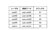
- FIG. 4 shows an example of a data table stored by the DB 324 of FIG.
- the data table of FIG. 4 includes user IDs, vein data, and office IDs.
- the user ID is identification information of the user who is the registrant
- the vein data is feature data representing features of the palm vein image of the user.
- Vein data is an example of registered biometric data.
- the office ID is identification information of the office 301-i to which the user belongs.
- the office ID of office 301-1 is "A1”
- the office ID of office 301-2 is "A2”
- the office ID of office 301-3 is "A3”.
- the user indicated by the user ID "user01” and the user indicated by the user ID “user02” belong to the office 301-1 indicated by the office ID "A1".
- the user indicated by the user ID “user03” belongs to the office 301-2 indicated by the office ID "A2".
- the user indicated by the user ID "user04” and the user indicated by the user ID “userxx” belong to the office 301-3 indicated by the office ID "A3".
- the user's vein data "user_vein01” indicated by the user ID "user01” and the user's vein data “user_vein02” indicated by the user ID “user02” belong to the group of the office 301-1.
- the user's vein data "user_vein03" indicated by the user ID "user03” belongs to the group of the office 301-2.
- the user's vein data "user_vein04" indicated by the user ID “user04” and the user's vein data “user_veinxx” indicated by the user ID “userxx” belong to the office 301-3 group.
- FIG. 5 shows a functional configuration example of the authentication device 322-i in FIG. Authentication device 322-i of FIG.
- the communication unit 513 communicates with the router 321 via the communication network 325 and communicates with the control device 323 and the DB 324 via the communication network 326 .
- the comparison unit 511 acquires one or more pieces of registered biometric data belonging to the group of the office 301 - i from the DB 324 via the communication unit 513 and stores the acquired registered biometric data in the storage unit 512 .
- the registered biometric data belonging to the group of the office 301-i corresponding to the authentication device 322-i is developed in the storage unit 512.
- FIG. 6 shows an example of a data table stored by the authentication devices 322-1 to 322-3 in FIG.
- FIG. 6(a) shows an example of a data table stored in the storage unit 512 of the authentication device 322-1.
- the data table of FIG. 6(a) includes user IDs, vein data, and office IDs of two users belonging to the group of office 301-1.
- FIG. 6(b) shows an example of a data table stored in the storage unit 512 of the authentication device 322-2.
- the data table in FIG. 6B includes user IDs, vein data, and office IDs of users belonging to the group of office 301-2.
- FIG. 6(c) shows an example of a data table stored in the storage unit 512 of the authentication device 322-3.
- the data table of FIG. 6(c) includes user IDs, vein data, and office IDs of two users belonging to the group of office 301-3.
- the comparison unit 511 uses the biometric data received from the processing device 313-i as the biometric data to be authenticated, and compares the biometric data to be authenticated with each registered biometric data in the storage unit 512 to obtain a 1:N ratio. Authenticate. The comparison unit 511 then transmits the authentication result of the 1:N authentication to the processing device 313-i via the communication unit 513.
- the authentication result indicates successful authentication.
- the authentication result indicates authentication failure.
- the comparison unit 511 can perform 1:N authentication using containers, for example.
- the data table containing the enrolled biometric data is implemented as data stored by the container.
- the container may act as an authenticator on behalf of authenticator 322-i.
- the processing device 313-i Upon receiving an authentication result indicating successful authentication from the authentication device 322-i, the processing device 313-i performs predetermined processing. On the other hand, when receiving an authentication result indicating authentication failure from the authentication device 322-i, the processing device 313-i does not perform the predetermined process.
- the predetermined process is a process of permitting the person to be authenticated to operate the multifunction device. If the processing device 313-i is a payment machine, the predetermined process is a process of paying for food or articles purchased by the person to be authenticated. If the processing device 313-i is a locker control device, the predetermined process is a process of unlocking the door of the locker. If the processing device 313-i is a gate control device, the predetermined processing is processing to open the gate.
- the operations of the sensor 312-i and the processor 314-i of the office 301-i are similar to those of the sensor 311-i and the processor 313-i.
- a user belonging to each office 301-i may move to another office 301-i due to a business trip or the like.
- the user indicated by the user ID "user01" is the user 303 belonging to the office 301-1.
- the user 303 uses the sensor 311-2 and the sensor 312-2 in the office 301-2.
- the registered biometric data of user 303 belongs to the group of office 301-1 and does not belong to the group of office 301-2, so it is not included in the data table of FIG. 6(b). Therefore, if the authentication device 322-2 performs 1:N authentication, authentication of the user 303 will fail.
- the mobile terminal device 315 owned by the user 303 and the control device 323 of the distributed authentication system 302 perform office switching processing.
- the mobile terminal device 315 is, for example, a smart phone, tablet, notebook personal computer, or wearable device.
- FIG. 7 shows a functional configuration example of the mobile terminal device 315 of FIG.
- Communication unit 714 communicates with distributed authentication system 302 via communication network 331 .
- the receiving unit 711 receives radio waves from GPS (Global Positioning System) satellites, and the detecting unit 712 detects the position of the mobile terminal device 315 from the received radio waves.
- the receiving unit 711 may receive radio waves from a wireless LAN access point such as Wi-Fi (registered trademark) instead of radio waves from GPS satellites, and detect the position of the mobile terminal device 315 from the received radio waves. good.
- the switching unit 713 transmits a switching request including the user ID and location information of the user 303 to the distributed authentication system 302 via the communication unit 714 .
- the location information of the user 303 information indicating the location of the mobile terminal device 315 detected by the detection unit 712 is used.
- User 303 location information may include, for example, latitude and longitude.
- the office switching process can be started without the user 303 being aware of it.
- the router 321 of the distributed authentication system 302 receives the switching request from the mobile terminal device 315 and transfers the received switching request to the control device 323 .
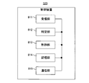
- FIG. 8 shows a functional configuration example of the control device 323 in FIG.
- the control device 323 of FIG. 8 includes a reception unit 811 , a specification unit 812 , a control unit 813 , a storage unit 814 and a communication unit 815 .
- the reception unit 811, the identification unit 812, and the control unit 813 correspond to the reception unit 111, the identification unit 112, and the control unit 113 in FIG. 1, respectively.
- the communication unit 815 communicates with the router 321 via the communication network 325, and communicates with the authentication devices 322-1 to 322-3 and the DB 324 via the communication network 326.
- Storage unit 814 stores an office mapping table including information on offices 301-1 to 301-3.
- FIG. 9 shows an example of an office mapping table stored in the storage unit 814 of FIG.
- the office mapping table of FIG. 9 includes area and office IDs.
- the area is information indicating the location of the office 301-i
- the office ID is identification information of the office 301-i. Areas may include, for example, latitude and longitude ranges.
- Office 301-1 indicated by office ID “A1” exists in area “R1"
- office 301-2 indicated by office ID “A2” exists in area “R2”
- office 301-2 indicated by office ID "A3” exists.
- 301-3 exists in area "R3”.
- the communication unit 815 receives a switching request from the router 321, and the accepting unit 811 accepts the received switching request.
- the specifying unit 812 specifies an area corresponding to the location information included in the accepted switching request, among the areas included in the office mapping table.
- the identifying unit 812 identifies, for example, an area including the latitude and longitude indicated by the positional information as the area corresponding to the positional information.
- the specifying unit 812 acquires the office ID from the entry including the specified area, and specifies the office 301-i indicated by the acquired office ID. Identify i.
- the control unit 813 transmits the user ID included in the accepted switching request to the DB 324 via the communication unit 815.
- the DB 324 extracts the office ID from the entry containing the received user ID in the data table and returns it to the control device 323 .
- the control unit 813 compares the office ID acquired from the office mapping table and the office ID received from the DB 324, and updates the data table of the DB 324 if the two office IDs are different. By updating the DB 324 when the two office IDs are different, unnecessary updates can be prevented when the user 303 moves within the same office 301-i.
- the control unit 813 transmits an update request including the user ID included in the switching request and the acquired office ID to the DB 324 via the communication unit 815.
- the DB 324 changes the office ID of the entry including the user ID included in the received update request to the office ID included in the update request.
- the office 301-i where the user is staying and the office 301-i with which the user is associated in the DB 324 will match.
- control unit 813 transmits an update instruction to the authentication devices 322-1 to 322-3 via the communication unit 815.
- the comparison unit 511 of each authentication device 322-i acquires one or more registered biometric data belonging to the group of the office 301-i from the DB 324 via the communication unit 513 according to the received update instruction. Then, the comparison unit 511 updates the data table in the storage unit 512 using the acquired registered biometric data. As a result, the authentication device 322-i associated with the office 301-i where the user is staying and the authentication device 322-i storing the registered biometric data of the user are matched.
- the control unit 813 When the office ID obtained from the office mapping table matches the office ID received from the DB 324, the control unit 813 does not update the data table of the DB 324.
- the switching request When the switching request is transmitted from the mobile terminal device 315 located in the office 301-2, the switching request includes the user ID "user01" of the user 303 and the location information corresponding to the area "R2" where the office 301-2 is located. including.
- the specifying unit 812 specifies the area "R2" among the areas included in the office mapping table, and acquires the office ID "A2" from the entry including the area "R2". Thereby, the identifying unit 812 identifies the office 301-2 and the authentication device 322-2 corresponding to the office 301-2.
- the control unit 813 transmits the user ID "user01" to the DB 324 and receives from the DB 324 the office ID "A1" associated with the user ID "user01".
- the office ID “A2” acquired from the office mapping table is different from the office ID “A1” received from the DB 324 , so the control unit 813 updates the data table of the DB 324 .
- the control unit 813 transmits an update request including the user ID "user01” and the office ID "A2" to the DB 324.
- the DB 324 changes the office ID "A1" of the entry including the user ID "user01” to the office ID "A2" included in the update request in the data table.
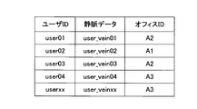
- FIG. 10 shows an example of the data table updated in the DB324.
- the office ID of the entry including the user ID "user01" in the data table of FIG. 4 is changed from "A1" to "A2".
- the control unit 813 transmits an update instruction to the authentication devices 322-1 to 322-3, and the comparison unit 511 of each authentication device 322-i retrieves the registered biometric data from the updated data table of the DB 324. It acquires and updates the data table in the storage unit 512 .
- the comparison unit 511 of the authentication device 322-1 erases the registered biometric data of the user 303 from the storage unit 512 of the authentication device 322-1, and the comparison unit 511 of the authentication device 322-2 deletes the The registered biometric data of the user 303 is added to the storage unit 512 of the .
- the process in which the control unit 813 transmits an update instruction to the authentication device 322-1 corresponds to the process in which the authentication device 322-1 erases the registered biometric data of the user 303. Further, the process in which the control unit 813 transmits the update instruction to the authentication device 322-2 corresponds to the process of storing the registered biometric data of the user 303 in the authentication device 322-2.
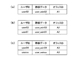
- FIG. 11 shows an example of the data table updated in the authentication devices 322-1 to 322-3.
- FIG. 11(a) shows an example of the data table updated in the storage unit 512 of the authentication device 322-1.
- the entry including the user ID "user01”, the vein data "user_vein01", and the office ID "A1" registered in the data table of FIG. 6(a) is deleted. .
- FIG. 11(b) shows an example of the updated data table in the storage unit 512 of the authentication device 322-2.
- an entry including user ID "user01”, vein data "user_vein01", and office ID "A2" is added to the data table of FIG. 6(b).
- FIG. 11(c) shows an example of the updated data table in the storage unit 512 of the authentication device 322-3.
- the data table of FIG. 11(c) is the same as the data table of FIG. 6(c).
- the sensor 311-2 of the office 301-2 acquires biometric information from the user 303 and outputs it to the processing device 313-2.
- the processing device 313 - 2 converts the biometric information output from the sensor 311 - 2 into biometric data and transmits the biometric data to the distributed authentication system 302 .
- the authentication device 322-2 performs 1:N authentication using the biometric data of the user 303 received from the processing device 313-2 as authentication target biometric data, and transmits the authentication result to the processing device 313-2. In this case, the authentication device 322-2 successfully authenticates the user 303 because the registered biometric data of the user 303 is included in the group of the office 301-2.
- the user 303 may use the mobile terminal device 315 to manually send the switching request to the distributed authentication system 302 . Also, the user 303 may use the processing device 313 - 2 or the processing device 314 - 2 instead of the mobile terminal device 315 to send the switching request to the distributed authentication system 302 .
- Each authentication device 322-i can perform 1:N authentication at high speed.
- the registered biometric data of the moved user performs 1:N authentication of the new office 301-i by office switching processing.
- authentication device 322-i Stored in authentication device 322-i.
- the registered biometric data distributed to the authentication devices 322-1 to 322-3 can be flexibly controlled, and the user can use services based on biometric authentication even at the office 301-i to which the user has moved. it becomes possible to
- FIG. 12 shows an example of biometric authentication processing performed by the biometric authentication system in FIG.
- the comparison unit 511 of the authentication device 322-1 acquires one or more entries belonging to the group of the office 301-1 from the data table of the DB 324 at a predetermined opportunity, and stores the acquired entries in the storage unit 512. (Step 1201).
- the predetermined trigger may be a fixed period, or may be when the DB 324 is updated. Updating the DB 324 includes adding new entries to the data table and updating or deleting existing entries.
- the user 303 belonging to the office 301-1 causes the sensor 311-1 to acquire biometric information when using the service provided by the processing device 313-1 (step 1202).
- Sensor 311-1 acquires biological information from user 303 and outputs it to processor 313-1 (step 1203).
- the processing device 313-1 converts the biometric information output from the sensor 311-1 into biometric data, and transmits an authentication request including the biometric data to the distributed authentication system 302 (step 1204).
- the router 321 of the distributed authentication system 302 receives the authentication request from the processing device 313-1, and based on the routing table, determines the authentication device 322-1 corresponding to the office 301-1 as the transfer destination (step 1205). The router 321 then transfers the received authentication request to the authentication device 322-1 (step 1206).
- the comparison unit 511 of the authentication device 322-1 uses the biometric data included in the authentication request received from the router 321 as the biometric data to be authenticated, and performs 1:N authentication on the biometric data to be authenticated (step 1207). The comparison unit 511 then transmits the authentication result of the 1:N authentication to the processing device 313-1 (step 1208).
- the processing device 313-1 When the received authentication result indicates successful authentication, the processing device 313-1 performs a predetermined process (step 1209) to provide a service to the user 303 (step 1210).
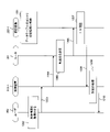
- FIG. 13 shows an example of office switching processing performed by the biometric authentication system in FIG. A user 303 belonging to the office 301-1 moves from the office 301-1 to the office 301-2 due to a business trip or the like (step 1301).
- the receiving unit 711 of the mobile terminal device 315 possessed by the user 303 detects the movement of the user 303 from changes in radio waves received from GPS satellites or wireless LAN access points (step 1302), and determines the position of the mobile terminal device 315. Detect (step 1303). Then, the switching unit 713 generates a switching request including the user ID “user01” of the user 303 and the location information corresponding to the area “R2” where the office 301-2 is located (step 1304), and distributes authentication. Send to system 302 (step 1305).
- the specifying unit 812 of the control device 323 included in the distributed authentication system 302 specifies the area "R2" corresponding to the location information included in the received switching request among the areas included in the office mapping table. Then, the identifying unit 812 identifies the office 301-2 and the authentication device 322-2 corresponding to the office 301-2 by acquiring the office ID "A2" from the entry including the area "R2" (step 1306).
- the control unit 813 acquires the office ID "A1" associated with the user ID "user01” from the DB324.
- the control unit 813 since the office ID "A2" obtained from the office mapping table is different from the office ID "A1” obtained from the DB 324, the control unit 813 updates the data table of the DB 324 (step 1307). .
- the office ID of the entry including the user ID "user01” is changed from "A1" to "A2".
- control unit 813 transmits update instructions to the authentication devices 322-1 to 322-3 (step 1308).
- Comparison unit 511 of each authentication device 322-i acquires one or more registered biometric data belonging to the group of office 301-i from DB 324 and updates the data table in storage unit 512 according to the received update instruction.
- the control unit 813 transmits a switching completion notification to the portable terminal device 315 (step 1309).
- the configuration of the information processing apparatus 101 in FIG. 1 is merely an example, and some components may be omitted or changed according to the usage or conditions of the information processing apparatus 101.
- the configuration of the biometric authentication system in FIG. 3 is merely an example, and some components may be omitted or changed according to the usage or conditions of the biometric authentication system.
- the number of offices 301-i may be two or four or more.
- the number of sensors and processing devices provided in each office 301-i may be one or three or more.
- the number of authentication devices 322-i included in the distributed authentication system 302 may be two or four or more.
- the flowchart in FIG. 2 is merely an example, and some of the processes may be omitted or changed according to the configuration or conditions of the information processing apparatus 101.
- the data tables shown in FIGS. 4, 6, 10, and 11 are only examples, and the data tables change according to the use of the biometric authentication system, the type of biometric information, and the number of registrants.
- the office mapping table shown in FIG. 9 is merely an example, and the office mapping table changes according to the number of offices 301-i.
- the biometric authentication process shown in FIG. 12 and the office switching process shown in FIG. 13 are merely examples, and the biometric authentication process and the office switching process change according to the configuration or conditions of the biometric authentication system.
- FIG. 14 shows a hardware configuration example of an information processing apparatus used as the information processing apparatus 101 in FIG. 1, the authentication apparatus 322-i in FIG. 3, the control apparatus 323, and the mobile terminal apparatus 315.
- the information processing device of FIG. 14 includes a CPU (Central Processing Unit) 1401, a memory 1402, an input device 1403, an output device 1404, an auxiliary storage device 1405, a media drive device 1406, and a network connection device 1407. These components are hardware and are connected to each other by bus 1408 .
- CPU Central Processing Unit
- the memory 1402 is, for example, a ROM (Read Only Memory), a RAM (Random Access Memory), a semiconductor memory such as a flash memory, and stores programs and data used for processing.
- Memory 1402 may operate as storage unit 512 in FIG. 5 or storage unit 814 in FIG.
- a CPU 1401 (processor) operates as the reception unit 111, the identification unit 112, and the control unit 113 in FIG. 1 by executing programs using the memory 1402, for example.
- the CPU 1401 also operates as the comparison unit 511 in FIG. 5 by executing a program using the memory 1402 .
- the CPU 1401 also operates as the switching unit 713 in FIG. 7 by executing a program using the memory 1402 .
- the CPU 1401 also operates as the reception unit 811, the identification unit 812, and the control unit 813 in FIG. 8 by executing programs using the memory 1402. FIG.
- the input device 1403 is, for example, a keyboard, pointing device, etc., and is used for inputting instructions or information from the user or operator.
- the output device 1404 is, for example, a display device, a printer, a speaker, etc., and is used for outputting an inquiry to a user or operator or processing results.
- the processing result may be an authentication result.
- the auxiliary storage device 1405 is, for example, a magnetic disk device, an optical disk device, a magneto-optical disk device, a tape device, or the like. Secondary storage device 1405 may be flash memory or a hard disk drive.
- the information processing apparatus can store programs and data in the auxiliary storage device 1405 and load them into the memory 1402 for use.
- a medium drive device 1406 drives a portable recording medium 1409 and accesses its recorded contents.
- a portable recording medium 1409 is a memory device, flexible disk, optical disk, magneto-optical disk, or the like.
- the portable recording medium 1409 may be a CD-ROM (Compact Disk Read Only Memory), a DVD (Digital Versatile Disk), a USB (Universal Serial Bus) memory, or the like.
- a user or operator can store programs and data in the portable recording medium 1409 and load them into the memory 1402 for use.
- a computer-readable recording medium for storing programs and data used for processing may be a physical (non-temporary) recording medium such as memory 1402, auxiliary storage device 1405, or portable recording medium 1409. is a medium.
- the network connection device 1407 is a communication interface circuit that is connected to the communication network 331, the communication network 325, or the communication network 326 and performs data conversion associated with communication.
- the information processing device can receive programs and data from an external device via the network connection device 1407, load them into the memory 1402, and use them.
- the network connection device 1407 may operate as the communication unit 513 in FIG. 5, the communication unit 714 in FIG. 7, or the communication unit 815 in FIG.
- the same information processing device as in FIG. 14 can be used.
- the information processing device does not need to include all the components shown in FIG. 14, and it is possible to omit some of the components depending on the application or conditions.
- the input device 1403 and the output device 1404 may be omitted if no user or operator interface is required. If the information processing device does not use the portable recording medium 1409, the medium drive device 1406 may be omitted.
Landscapes
- Engineering & Computer Science (AREA)
- Computer Security & Cryptography (AREA)
- Theoretical Computer Science (AREA)
- Computer Hardware Design (AREA)
- Software Systems (AREA)
- Physics & Mathematics (AREA)
- General Engineering & Computer Science (AREA)
- General Physics & Mathematics (AREA)
- Mobile Radio Communication Systems (AREA)
Priority Applications (2)
| Application Number | Priority Date | Filing Date | Title |
|---|---|---|---|
| PCT/JP2021/021198 WO2022254654A1 (ja) | 2021-06-03 | 2021-06-03 | 記憶制御方法、情報処理装置、記憶制御システム、及び記憶制御プログラム |
| JP2023525278A JPWO2022254654A1 (https=) | 2021-06-03 | 2021-06-03 |
Applications Claiming Priority (1)
| Application Number | Priority Date | Filing Date | Title |
|---|---|---|---|
| PCT/JP2021/021198 WO2022254654A1 (ja) | 2021-06-03 | 2021-06-03 | 記憶制御方法、情報処理装置、記憶制御システム、及び記憶制御プログラム |
Publications (1)
| Publication Number | Publication Date |
|---|---|
| WO2022254654A1 true WO2022254654A1 (ja) | 2022-12-08 |
Family
ID=84324026
Family Applications (1)
| Application Number | Title | Priority Date | Filing Date |
|---|---|---|---|
| PCT/JP2021/021198 Ceased WO2022254654A1 (ja) | 2021-06-03 | 2021-06-03 | 記憶制御方法、情報処理装置、記憶制御システム、及び記憶制御プログラム |
Country Status (2)
| Country | Link |
|---|---|
| JP (1) | JPWO2022254654A1 (https=) |
| WO (1) | WO2022254654A1 (https=) |
Cited By (1)
| Publication number | Priority date | Publication date | Assignee | Title |
|---|---|---|---|---|
| WO2024194962A1 (ja) * | 2023-03-17 | 2024-09-26 | 日本電信電話株式会社 | 生体認証システム、生体情報配備場所決定装置、生体情報配備場所決定方法、及びプログラム |
Citations (4)
| Publication number | Priority date | Publication date | Assignee | Title |
|---|---|---|---|---|
| JP2008021071A (ja) * | 2006-07-12 | 2008-01-31 | Fujitsu Ltd | 個人認証装置および個人認証方法 |
| JP2009230695A (ja) * | 2008-03-25 | 2009-10-08 | Oki Electric Ind Co Ltd | 事業所管理サーバ、出張所認証装置、出張所処理端末、出張所の開所システム、プログラム |
| JP2010191856A (ja) * | 2009-02-20 | 2010-09-02 | Fujitsu Ltd | 照合装置及び認証装置 |
| US20200322792A1 (en) * | 2017-12-20 | 2020-10-08 | Maxell, Ltd. | Terminal device, personal authentication system and personal authentication method |
-
2021
- 2021-06-03 WO PCT/JP2021/021198 patent/WO2022254654A1/ja not_active Ceased
- 2021-06-03 JP JP2023525278A patent/JPWO2022254654A1/ja active Pending
Patent Citations (4)
| Publication number | Priority date | Publication date | Assignee | Title |
|---|---|---|---|---|
| JP2008021071A (ja) * | 2006-07-12 | 2008-01-31 | Fujitsu Ltd | 個人認証装置および個人認証方法 |
| JP2009230695A (ja) * | 2008-03-25 | 2009-10-08 | Oki Electric Ind Co Ltd | 事業所管理サーバ、出張所認証装置、出張所処理端末、出張所の開所システム、プログラム |
| JP2010191856A (ja) * | 2009-02-20 | 2010-09-02 | Fujitsu Ltd | 照合装置及び認証装置 |
| US20200322792A1 (en) * | 2017-12-20 | 2020-10-08 | Maxell, Ltd. | Terminal device, personal authentication system and personal authentication method |
Cited By (1)
| Publication number | Priority date | Publication date | Assignee | Title |
|---|---|---|---|---|
| WO2024194962A1 (ja) * | 2023-03-17 | 2024-09-26 | 日本電信電話株式会社 | 生体認証システム、生体情報配備場所決定装置、生体情報配備場所決定方法、及びプログラム |
Also Published As
| Publication number | Publication date |
|---|---|
| JPWO2022254654A1 (https=) | 2022-12-08 |
Similar Documents
| Publication | Publication Date | Title |
|---|---|---|
| EP3504859B1 (en) | Remote usage of locally stored biometric authentication data | |
| US8913270B2 (en) | Authentication system having an authentication apparatus including an authentication unit configured to search records of identification information associated with group information to find matching identification information matching obtained identification information of a user, authentication method, and apparatus | |
| JP5458597B2 (ja) | 照合装置及び認証装置 | |
| US9204298B2 (en) | Multilevel authentication | |
| US20180211093A1 (en) | Method of processing fingerprint information | |
| US20100045787A1 (en) | Authenticating apparatus, authenticating system, and authenticating method | |
| US11070549B2 (en) | Electronic mechanism to self-authenticate and automate actions | |
| JP7620238B2 (ja) | 管理サーバ、テレワーク管理支援システム、テレワーク管理支援方法ならびにプログラム | |
| US7817825B2 (en) | Apparatus, system and method for person verification | |
| JP2014119865A (ja) | 情報処理システム、情報処理方法、機器、認証装置及びプログラム | |
| US20130065556A1 (en) | Multilevel Authentication | |
| US12267320B2 (en) | Multi-user biometric authentication | |
| JP2018120375A (ja) | システム及び方法 | |
| CN114915453A (zh) | 访问响应方法以及装置 | |
| US10936706B2 (en) | Biometric authentication | |
| US9201406B2 (en) | Information processing apparatus, information processing method, and computer-readable recording medium storing a program | |
| WO2022254654A1 (ja) | 記憶制御方法、情報処理装置、記憶制御システム、及び記憶制御プログラム | |
| US12574372B2 (en) | Sharing a biometric token across platforms and devices for authentication | |
| JP2012118833A (ja) | アクセス制御方法 | |
| US12073839B2 (en) | Authentication by speech at a machine | |
| JP2018207344A (ja) | 画像処理システム、画像形成装置及びプログラム | |
| JP6829698B2 (ja) | 認証システムおよび認証方法 | |
| US10606995B2 (en) | Character input device, character input method, and character input program | |
| JP2010267198A (ja) | 認証装置、方法、及び、プログラム | |
| KR101988365B1 (ko) | 얼굴 인식 시스템 및 그 방법 |
Legal Events
| Date | Code | Title | Description |
|---|---|---|---|
| 121 | Ep: the epo has been informed by wipo that ep was designated in this application |
Ref document number: 21944155 Country of ref document: EP Kind code of ref document: A1 |
|
| WWE | Wipo information: entry into national phase |
Ref document number: 2023525278 Country of ref document: JP |
|
| NENP | Non-entry into the national phase |
Ref country code: DE |
|
| 122 | Ep: pct application non-entry in european phase |
Ref document number: 21944155 Country of ref document: EP Kind code of ref document: A1 |