WO2022250168A1 - 方向性電磁鋼板 - Google Patents
方向性電磁鋼板 Download PDFInfo
- Publication number
- WO2022250168A1 WO2022250168A1 PCT/JP2022/021936 JP2022021936W WO2022250168A1 WO 2022250168 A1 WO2022250168 A1 WO 2022250168A1 JP 2022021936 W JP2022021936 W JP 2022021936W WO 2022250168 A1 WO2022250168 A1 WO 2022250168A1
- Authority
- WO
- WIPO (PCT)
- Prior art keywords
- atomic
- less
- content
- steel sheet
- crystalline
- Prior art date
Links
- 229910000831 Steel Inorganic materials 0.000 title claims abstract description 136
- 239000010959 steel Substances 0.000 title claims abstract description 136
- 238000000576 coating method Methods 0.000 claims abstract description 243
- 239000011248 coating agent Substances 0.000 claims abstract description 242
- NBIIXXVUZAFLBC-UHFFFAOYSA-N Phosphoric acid Chemical compound OP(O)(O)=O NBIIXXVUZAFLBC-UHFFFAOYSA-N 0.000 claims abstract description 241
- 229910000147 aluminium phosphate Inorganic materials 0.000 claims abstract description 121
- 239000013078 crystal Substances 0.000 claims abstract description 26
- 229910052720 vanadium Inorganic materials 0.000 claims abstract description 18
- 229910052750 molybdenum Inorganic materials 0.000 claims abstract description 15
- 229910052726 zirconium Inorganic materials 0.000 claims abstract description 15
- 229910052721 tungsten Inorganic materials 0.000 claims abstract description 14
- 229910001392 phosphorus oxide Inorganic materials 0.000 claims abstract description 7
- VSAISIQCTGDGPU-UHFFFAOYSA-N tetraphosphorus hexaoxide Chemical compound O1P(O2)OP3OP1OP2O3 VSAISIQCTGDGPU-UHFFFAOYSA-N 0.000 claims abstract description 6
- BHEPBYXIRTUNPN-UHFFFAOYSA-N hydridophosphorus(.) (triplet) Chemical compound [PH] BHEPBYXIRTUNPN-UHFFFAOYSA-N 0.000 claims description 131
- 229910001224 Grain-oriented electrical steel Inorganic materials 0.000 claims description 100
- 229910000976 Electrical steel Inorganic materials 0.000 claims description 36
- 239000000463 material Substances 0.000 claims description 17
- 238000005520 cutting process Methods 0.000 claims description 12
- OAICVXFJPJFONN-UHFFFAOYSA-N Phosphorus Chemical compound [P] OAICVXFJPJFONN-UHFFFAOYSA-N 0.000 claims description 4
- 230000026731 phosphorylation Effects 0.000 claims description 4
- 238000006366 phosphorylation reaction Methods 0.000 claims description 4
- 229960004838 phosphoric acid Drugs 0.000 abstract 2
- 235000011007 phosphoric acid Nutrition 0.000 abstract 2
- XEEYBQQBJWHFJM-UHFFFAOYSA-N Iron Chemical compound [Fe] XEEYBQQBJWHFJM-UHFFFAOYSA-N 0.000 description 126
- 238000000137 annealing Methods 0.000 description 122
- 238000000034 method Methods 0.000 description 92
- 229910052742 iron Inorganic materials 0.000 description 48
- 230000008569 process Effects 0.000 description 44
- 239000000203 mixture Substances 0.000 description 41
- 238000010438 heat treatment Methods 0.000 description 39
- CPLXHLVBOLITMK-UHFFFAOYSA-N Magnesium oxide Chemical compound [Mg]=O CPLXHLVBOLITMK-UHFFFAOYSA-N 0.000 description 35
- 239000011572 manganese Substances 0.000 description 35
- 229910052839 forsterite Inorganic materials 0.000 description 33
- HCWCAKKEBCNQJP-UHFFFAOYSA-N magnesium orthosilicate Chemical compound [Mg+2].[Mg+2].[O-][Si]([O-])([O-])[O-] HCWCAKKEBCNQJP-UHFFFAOYSA-N 0.000 description 33
- 229910019142 PO4 Inorganic materials 0.000 description 32
- 239000011651 chromium Substances 0.000 description 32
- 235000021317 phosphate Nutrition 0.000 description 32
- 239000010452 phosphate Substances 0.000 description 31
- NBIIXXVUZAFLBC-UHFFFAOYSA-K phosphate Chemical compound [O-]P([O-])([O-])=O NBIIXXVUZAFLBC-UHFFFAOYSA-K 0.000 description 30
- 238000005261 decarburization Methods 0.000 description 29
- PXHVJJICTQNCMI-UHFFFAOYSA-N nickel Substances [Ni] PXHVJJICTQNCMI-UHFFFAOYSA-N 0.000 description 29
- 239000011777 magnesium Substances 0.000 description 27
- 239000012535 impurity Substances 0.000 description 25
- 238000004519 manufacturing process Methods 0.000 description 24
- 239000011669 selenium Substances 0.000 description 24
- 238000005098 hot rolling Methods 0.000 description 23
- 238000007254 oxidation reaction Methods 0.000 description 23
- 239000000126 substance Substances 0.000 description 23
- 238000004458 analytical method Methods 0.000 description 21
- 239000012467 final product Substances 0.000 description 21
- 230000003647 oxidation Effects 0.000 description 21
- 229910052717 sulfur Inorganic materials 0.000 description 21
- 238000005097 cold rolling Methods 0.000 description 20
- 238000010894 electron beam technology Methods 0.000 description 18
- 229910052757 nitrogen Inorganic materials 0.000 description 18
- 238000001953 recrystallisation Methods 0.000 description 18
- 229910052711 selenium Inorganic materials 0.000 description 18
- 239000000243 solution Substances 0.000 description 18
- 230000000694 effects Effects 0.000 description 17
- 239000000395 magnesium oxide Substances 0.000 description 17
- IJGRMHOSHXDMSA-UHFFFAOYSA-N Atomic nitrogen Chemical compound N#N IJGRMHOSHXDMSA-UHFFFAOYSA-N 0.000 description 16
- 229910052782 aluminium Inorganic materials 0.000 description 16
- 239000008199 coating composition Substances 0.000 description 16
- 230000001965 increasing effect Effects 0.000 description 16
- 230000005381 magnetic domain Effects 0.000 description 16
- 229910018072 Al 2 O 3 Inorganic materials 0.000 description 15
- VYPSYNLAJGMNEJ-UHFFFAOYSA-N Silicium dioxide Chemical compound O=[Si]=O VYPSYNLAJGMNEJ-UHFFFAOYSA-N 0.000 description 15
- 239000003112 inhibitor Substances 0.000 description 15
- 230000015572 biosynthetic process Effects 0.000 description 14
- 239000010949 copper Substances 0.000 description 14
- 238000005554 pickling Methods 0.000 description 14
- 229910052710 silicon Inorganic materials 0.000 description 14
- 229910052799 carbon Inorganic materials 0.000 description 13
- 238000001816 cooling Methods 0.000 description 13
- 239000010955 niobium Substances 0.000 description 13
- 238000005121 nitriding Methods 0.000 description 13
- 238000005096 rolling process Methods 0.000 description 13
- 239000010936 titanium Substances 0.000 description 13
- 239000011701 zinc Substances 0.000 description 13
- 238000009413 insulation Methods 0.000 description 12
- 238000004445 quantitative analysis Methods 0.000 description 12
- 229910052698 phosphorus Inorganic materials 0.000 description 11
- 238000012360 testing method Methods 0.000 description 11
- 229910052804 chromium Inorganic materials 0.000 description 10
- 229910052749 magnesium Inorganic materials 0.000 description 10
- 229910052748 manganese Inorganic materials 0.000 description 10
- 229910052759 nickel Inorganic materials 0.000 description 10
- 239000002244 precipitate Substances 0.000 description 10
- 230000002411 adverse Effects 0.000 description 9
- QGZKDVFQNNGYKY-UHFFFAOYSA-N Ammonia Chemical compound N QGZKDVFQNNGYKY-UHFFFAOYSA-N 0.000 description 8
- 239000010960 cold rolled steel Substances 0.000 description 8
- 239000008119 colloidal silica Substances 0.000 description 8
- 229910052760 oxygen Inorganic materials 0.000 description 8
- XLYOFNOQVPJJNP-UHFFFAOYSA-N water Substances O XLYOFNOQVPJJNP-UHFFFAOYSA-N 0.000 description 8
- 239000003795 chemical substances by application Substances 0.000 description 7
- ZCDOYSPFYFSLEW-UHFFFAOYSA-N chromate(2-) Chemical compound [O-][Cr]([O-])(=O)=O ZCDOYSPFYFSLEW-UHFFFAOYSA-N 0.000 description 7
- 239000007789 gas Substances 0.000 description 7
- 239000001257 hydrogen Substances 0.000 description 7
- 229910052739 hydrogen Inorganic materials 0.000 description 7
- 229910052787 antimony Inorganic materials 0.000 description 6
- 229910052796 boron Inorganic materials 0.000 description 6
- 230000007423 decrease Effects 0.000 description 6
- 230000009467 reduction Effects 0.000 description 6
- 230000003746 surface roughness Effects 0.000 description 6
- 229910052718 tin Inorganic materials 0.000 description 6
- UFHFLCQGNIYNRP-UHFFFAOYSA-N Hydrogen Chemical compound [H][H] UFHFLCQGNIYNRP-UHFFFAOYSA-N 0.000 description 5
- 229910052802 copper Inorganic materials 0.000 description 5
- 238000010191 image analysis Methods 0.000 description 5
- 239000011159 matrix material Substances 0.000 description 5
- 229910052758 niobium Inorganic materials 0.000 description 5
- 230000035882 stress Effects 0.000 description 5
- 229910052719 titanium Inorganic materials 0.000 description 5
- QAOWNCQODCNURD-UHFFFAOYSA-N Sulfuric acid Chemical compound OS(O)(=O)=O QAOWNCQODCNURD-UHFFFAOYSA-N 0.000 description 4
- 239000002253 acid Substances 0.000 description 4
- 229910021529 ammonia Inorganic materials 0.000 description 4
- 230000001747 exhibiting effect Effects 0.000 description 4
- -1 inclusions Substances 0.000 description 4
- 239000011261 inert gas Substances 0.000 description 4
- 230000005389 magnetism Effects 0.000 description 4
- 238000005259 measurement Methods 0.000 description 4
- 229910052751 metal Inorganic materials 0.000 description 4
- 239000002184 metal Substances 0.000 description 4
- 229910001463 metal phosphate Inorganic materials 0.000 description 4
- 238000001556 precipitation Methods 0.000 description 4
- 238000012545 processing Methods 0.000 description 4
- 239000000047 product Substances 0.000 description 4
- 239000002994 raw material Substances 0.000 description 4
- 229910052725 zinc Inorganic materials 0.000 description 4
- OKTJSMMVPCPJKN-UHFFFAOYSA-N Carbon Chemical compound [C] OKTJSMMVPCPJKN-UHFFFAOYSA-N 0.000 description 3
- PWHULOQIROXLJO-UHFFFAOYSA-N Manganese Chemical compound [Mn] PWHULOQIROXLJO-UHFFFAOYSA-N 0.000 description 3
- HEMHJVSKTPXQMS-UHFFFAOYSA-M Sodium hydroxide Chemical compound [OH-].[Na+] HEMHJVSKTPXQMS-UHFFFAOYSA-M 0.000 description 3
- WGLPBDUCMAPZCE-UHFFFAOYSA-N Trioxochromium Chemical compound O=[Cr](=O)=O WGLPBDUCMAPZCE-UHFFFAOYSA-N 0.000 description 3
- 238000005162 X-ray Laue diffraction Methods 0.000 description 3
- XAGFODPZIPBFFR-UHFFFAOYSA-N aluminium Chemical compound [Al] XAGFODPZIPBFFR-UHFFFAOYSA-N 0.000 description 3
- 238000005452 bending Methods 0.000 description 3
- 229910052797 bismuth Inorganic materials 0.000 description 3
- 239000000470 constituent Substances 0.000 description 3
- 238000000354 decomposition reaction Methods 0.000 description 3
- 230000006866 deterioration Effects 0.000 description 3
- KZHJGOXRZJKJNY-UHFFFAOYSA-N dioxosilane;oxo(oxoalumanyloxy)alumane Chemical compound O=[Si]=O.O=[Si]=O.O=[Al]O[Al]=O.O=[Al]O[Al]=O.O=[Al]O[Al]=O KZHJGOXRZJKJNY-UHFFFAOYSA-N 0.000 description 3
- 238000002149 energy-dispersive X-ray emission spectroscopy Methods 0.000 description 3
- 230000004907 flux Effects 0.000 description 3
- 238000009776 industrial production Methods 0.000 description 3
- 229910052863 mullite Inorganic materials 0.000 description 3
- 229910052814 silicon oxide Inorganic materials 0.000 description 3
- 239000007787 solid Substances 0.000 description 3
- 238000005406 washing Methods 0.000 description 3
- XKRFYHLGVUSROY-UHFFFAOYSA-N Argon Chemical compound [Ar] XKRFYHLGVUSROY-UHFFFAOYSA-N 0.000 description 2
- RYGMFSIKBFXOCR-UHFFFAOYSA-N Copper Chemical compound [Cu] RYGMFSIKBFXOCR-UHFFFAOYSA-N 0.000 description 2
- VEXZGXHMUGYJMC-UHFFFAOYSA-N Hydrochloric acid Chemical compound Cl VEXZGXHMUGYJMC-UHFFFAOYSA-N 0.000 description 2
- GRYLNZFGIOXLOG-UHFFFAOYSA-N Nitric acid Chemical compound O[N+]([O-])=O GRYLNZFGIOXLOG-UHFFFAOYSA-N 0.000 description 2
- BUGBHKTXTAQXES-UHFFFAOYSA-N Selenium Chemical compound [Se] BUGBHKTXTAQXES-UHFFFAOYSA-N 0.000 description 2
- XUIMIQQOPSSXEZ-UHFFFAOYSA-N Silicon Chemical compound [Si] XUIMIQQOPSSXEZ-UHFFFAOYSA-N 0.000 description 2
- NINIDFKCEFEMDL-UHFFFAOYSA-N Sulfur Chemical compound [S] NINIDFKCEFEMDL-UHFFFAOYSA-N 0.000 description 2
- 238000010521 absorption reaction Methods 0.000 description 2
- 230000004075 alteration Effects 0.000 description 2
- QVGXLLKOCUKJST-UHFFFAOYSA-N atomic oxygen Chemical compound [O] QVGXLLKOCUKJST-UHFFFAOYSA-N 0.000 description 2
- 230000005540 biological transmission Effects 0.000 description 2
- 238000004040 coloring Methods 0.000 description 2
- 238000012790 confirmation Methods 0.000 description 2
- 238000012937 correction Methods 0.000 description 2
- 230000001186 cumulative effect Effects 0.000 description 2
- 230000007547 defect Effects 0.000 description 2
- 238000010586 diagram Methods 0.000 description 2
- 239000006185 dispersion Substances 0.000 description 2
- 238000001035 drying Methods 0.000 description 2
- 238000010292 electrical insulation Methods 0.000 description 2
- 230000002708 enhancing effect Effects 0.000 description 2
- 150000002431 hydrogen Chemical class 0.000 description 2
- 230000001771 impaired effect Effects 0.000 description 2
- 238000002354 inductively-coupled plasma atomic emission spectroscopy Methods 0.000 description 2
- 230000002401 inhibitory effect Effects 0.000 description 2
- 230000000670 limiting effect Effects 0.000 description 2
- 239000007788 liquid Substances 0.000 description 2
- 150000002739 metals Chemical class 0.000 description 2
- 229910017604 nitric acid Inorganic materials 0.000 description 2
- 150000004767 nitrides Chemical class 0.000 description 2
- 239000001301 oxygen Substances 0.000 description 2
- 230000036961 partial effect Effects 0.000 description 2
- 238000005498 polishing Methods 0.000 description 2
- 238000006116 polymerization reaction Methods 0.000 description 2
- 239000011148 porous material Substances 0.000 description 2
- FGIUAXJPYTZDNR-UHFFFAOYSA-N potassium nitrate Chemical compound [K+].[O-][N+]([O-])=O FGIUAXJPYTZDNR-UHFFFAOYSA-N 0.000 description 2
- 230000002829 reductive effect Effects 0.000 description 2
- 229920006395 saturated elastomer Polymers 0.000 description 2
- 238000000926 separation method Methods 0.000 description 2
- 239000010703 silicon Substances 0.000 description 2
- 239000000377 silicon dioxide Substances 0.000 description 2
- VWDWKYIASSYTQR-UHFFFAOYSA-N sodium nitrate Chemical compound [Na+].[O-][N+]([O-])=O VWDWKYIASSYTQR-UHFFFAOYSA-N 0.000 description 2
- LPXPTNMVRIOKMN-UHFFFAOYSA-M sodium nitrite Chemical compound [Na+].[O-]N=O LPXPTNMVRIOKMN-UHFFFAOYSA-M 0.000 description 2
- 239000006104 solid solution Substances 0.000 description 2
- 239000011593 sulfur Substances 0.000 description 2
- ZOXJGFHDIHLPTG-UHFFFAOYSA-N Boron Chemical compound [B] ZOXJGFHDIHLPTG-UHFFFAOYSA-N 0.000 description 1
- VYZAMTAEIAYCRO-UHFFFAOYSA-N Chromium Chemical compound [Cr] VYZAMTAEIAYCRO-UHFFFAOYSA-N 0.000 description 1
- FYYHWMGAXLPEAU-UHFFFAOYSA-N Magnesium Chemical compound [Mg] FYYHWMGAXLPEAU-UHFFFAOYSA-N 0.000 description 1
- ZOKXTWBITQBERF-UHFFFAOYSA-N Molybdenum Chemical compound [Mo] ZOKXTWBITQBERF-UHFFFAOYSA-N 0.000 description 1
- IOVCWXUNBOPUCH-UHFFFAOYSA-N Nitrous acid Chemical group ON=O IOVCWXUNBOPUCH-UHFFFAOYSA-N 0.000 description 1
- ABLZXFCXXLZCGV-UHFFFAOYSA-N Phosphorous acid Chemical compound OP(O)=O ABLZXFCXXLZCGV-UHFFFAOYSA-N 0.000 description 1
- 206010039509 Scab Diseases 0.000 description 1
- 229910004298 SiO 2 Inorganic materials 0.000 description 1
- 229910004283 SiO 4 Inorganic materials 0.000 description 1
- ATJFFYVFTNAWJD-UHFFFAOYSA-N Tin Chemical compound [Sn] ATJFFYVFTNAWJD-UHFFFAOYSA-N 0.000 description 1
- GWEVSGVZZGPLCZ-UHFFFAOYSA-N Titan oxide Chemical compound O=[Ti]=O GWEVSGVZZGPLCZ-UHFFFAOYSA-N 0.000 description 1
- RTAQQCXQSZGOHL-UHFFFAOYSA-N Titanium Chemical compound [Ti] RTAQQCXQSZGOHL-UHFFFAOYSA-N 0.000 description 1
- 238000002441 X-ray diffraction Methods 0.000 description 1
- AZFNGPAYDKGCRB-XCPIVNJJSA-M [(1s,2s)-2-amino-1,2-diphenylethyl]-(4-methylphenyl)sulfonylazanide;chlororuthenium(1+);1-methyl-4-propan-2-ylbenzene Chemical compound [Ru+]Cl.CC(C)C1=CC=C(C)C=C1.C1=CC(C)=CC=C1S(=O)(=O)[N-][C@@H](C=1C=CC=CC=1)[C@@H](N)C1=CC=CC=C1 AZFNGPAYDKGCRB-XCPIVNJJSA-M 0.000 description 1
- 150000007513 acids Chemical class 0.000 description 1
- 239000012670 alkaline solution Substances 0.000 description 1
- 238000005275 alloying Methods 0.000 description 1
- PNEYBMLMFCGWSK-UHFFFAOYSA-N aluminium oxide Inorganic materials [O-2].[O-2].[O-2].[Al+3].[Al+3] PNEYBMLMFCGWSK-UHFFFAOYSA-N 0.000 description 1
- ILRRQNADMUWWFW-UHFFFAOYSA-K aluminium phosphate Chemical compound O1[Al]2OP1(=O)O2 ILRRQNADMUWWFW-UHFFFAOYSA-K 0.000 description 1
- 238000004873 anchoring Methods 0.000 description 1
- WATWJIUSRGPENY-UHFFFAOYSA-N antimony atom Chemical compound [Sb] WATWJIUSRGPENY-UHFFFAOYSA-N 0.000 description 1
- 239000007864 aqueous solution Substances 0.000 description 1
- 229910052786 argon Inorganic materials 0.000 description 1
- 125000004429 atom Chemical group 0.000 description 1
- 239000012752 auxiliary agent Substances 0.000 description 1
- SJKRCWUQJZIWQB-UHFFFAOYSA-N azane;chromium Chemical compound N.[Cr] SJKRCWUQJZIWQB-UHFFFAOYSA-N 0.000 description 1
- RRZKHZBOZDIQJG-UHFFFAOYSA-N azane;manganese Chemical compound N.[Mn] RRZKHZBOZDIQJG-UHFFFAOYSA-N 0.000 description 1
- JRPBQTZRNDNNOP-UHFFFAOYSA-N barium titanate Chemical compound [Ba+2].[Ba+2].[O-][Ti]([O-])([O-])[O-] JRPBQTZRNDNNOP-UHFFFAOYSA-N 0.000 description 1
- 229910002113 barium titanate Inorganic materials 0.000 description 1
- JCXGWMGPZLAOME-UHFFFAOYSA-N bismuth atom Chemical compound [Bi] JCXGWMGPZLAOME-UHFFFAOYSA-N 0.000 description 1
- 229910021538 borax Inorganic materials 0.000 description 1
- KGBXLFKZBHKPEV-UHFFFAOYSA-N boric acid Chemical compound OB(O)O KGBXLFKZBHKPEV-UHFFFAOYSA-N 0.000 description 1
- 239000004327 boric acid Substances 0.000 description 1
- 238000005266 casting Methods 0.000 description 1
- 230000008859 change Effects 0.000 description 1
- 238000006243 chemical reaction Methods 0.000 description 1
- XTEGARKTQYYJKE-UHFFFAOYSA-N chloric acid Chemical compound OCl(=O)=O XTEGARKTQYYJKE-UHFFFAOYSA-N 0.000 description 1
- 229940005991 chloric acid Drugs 0.000 description 1
- QBWCMBCROVPCKQ-UHFFFAOYSA-N chlorous acid Chemical compound OCl=O QBWCMBCROVPCKQ-UHFFFAOYSA-N 0.000 description 1
- 229940077239 chlorous acid Drugs 0.000 description 1
- 229910000423 chromium oxide Inorganic materials 0.000 description 1
- 229910052681 coesite Inorganic materials 0.000 description 1
- 230000000052 comparative effect Effects 0.000 description 1
- 150000001875 compounds Chemical class 0.000 description 1
- 238000009749 continuous casting Methods 0.000 description 1
- 230000007797 corrosion Effects 0.000 description 1
- 238000005260 corrosion Methods 0.000 description 1
- 229910052906 cristobalite Inorganic materials 0.000 description 1
- 238000002447 crystallographic data Methods 0.000 description 1
- 230000006378 damage Effects 0.000 description 1
- 230000002950 deficient Effects 0.000 description 1
- 230000003111 delayed effect Effects 0.000 description 1
- 238000009826 distribution Methods 0.000 description 1
- 238000005485 electric heating Methods 0.000 description 1
- 238000000866 electrolytic etching Methods 0.000 description 1
- 238000002524 electron diffraction data Methods 0.000 description 1
- 238000000921 elemental analysis Methods 0.000 description 1
- 238000000724 energy-dispersive X-ray spectrum Methods 0.000 description 1
- 238000011156 evaluation Methods 0.000 description 1
- 230000005284 excitation Effects 0.000 description 1
- 230000036571 hydration Effects 0.000 description 1
- 238000006703 hydration reaction Methods 0.000 description 1
- 238000007654 immersion Methods 0.000 description 1
- 230000006872 improvement Effects 0.000 description 1
- 230000006698 induction Effects 0.000 description 1
- 238000009434 installation Methods 0.000 description 1
- 230000010354 integration Effects 0.000 description 1
- 238000010884 ion-beam technique Methods 0.000 description 1
- 229910001337 iron nitride Inorganic materials 0.000 description 1
- 230000001678 irradiating effect Effects 0.000 description 1
- 238000003475 lamination Methods 0.000 description 1
- 238000000691 measurement method Methods 0.000 description 1
- 230000004048 modification Effects 0.000 description 1
- 238000012986 modification Methods 0.000 description 1
- 239000011733 molybdenum Substances 0.000 description 1
- 229910000476 molybdenum oxide Inorganic materials 0.000 description 1
- 230000007935 neutral effect Effects 0.000 description 1
- GUCVJGMIXFAOAE-UHFFFAOYSA-N niobium atom Chemical compound [Nb] GUCVJGMIXFAOAE-UHFFFAOYSA-N 0.000 description 1
- PQQKPALAQIIWST-UHFFFAOYSA-N oxomolybdenum Chemical compound [Mo]=O PQQKPALAQIIWST-UHFFFAOYSA-N 0.000 description 1
- HWGNBUXHKFFFIH-UHFFFAOYSA-I pentasodium;[oxido(phosphonatooxy)phosphoryl] phosphate Chemical compound [Na+].[Na+].[Na+].[Na+].[Na+].[O-]P([O-])(=O)OP([O-])(=O)OP([O-])([O-])=O HWGNBUXHKFFFIH-UHFFFAOYSA-I 0.000 description 1
- MPNNOLHYOHFJKL-UHFFFAOYSA-N peroxyphosphoric acid Chemical compound OOP(O)(O)=O MPNNOLHYOHFJKL-UHFFFAOYSA-N 0.000 description 1
- 125000002467 phosphate group Chemical group [H]OP(=O)(O[H])O[*] 0.000 description 1
- 150000003013 phosphoric acid derivatives Chemical class 0.000 description 1
- 150000003016 phosphoric acids Chemical class 0.000 description 1
- 239000011574 phosphorus Substances 0.000 description 1
- LFGREXWGYUGZLY-UHFFFAOYSA-N phosphoryl Chemical class [P]=O LFGREXWGYUGZLY-UHFFFAOYSA-N 0.000 description 1
- 239000000049 pigment Substances 0.000 description 1
- 235000010333 potassium nitrate Nutrition 0.000 description 1
- 239000004323 potassium nitrate Substances 0.000 description 1
- 235000010289 potassium nitrite Nutrition 0.000 description 1
- 239000004304 potassium nitrite Substances 0.000 description 1
- 239000000843 powder Substances 0.000 description 1
- 239000011164 primary particle Substances 0.000 description 1
- 238000000746 purification Methods 0.000 description 1
- 230000008439 repair process Effects 0.000 description 1
- 238000001350 scanning transmission electron microscopy Methods 0.000 description 1
- 238000007652 sheet-forming process Methods 0.000 description 1
- 235000012239 silicon dioxide Nutrition 0.000 description 1
- 239000002002 slurry Substances 0.000 description 1
- 238000002791 soaking Methods 0.000 description 1
- UKLNMMHNWFDKNT-UHFFFAOYSA-M sodium chlorite Chemical compound [Na+].[O-]Cl=O UKLNMMHNWFDKNT-UHFFFAOYSA-M 0.000 description 1
- 229960002218 sodium chlorite Drugs 0.000 description 1
- 235000010344 sodium nitrate Nutrition 0.000 description 1
- 239000004317 sodium nitrate Substances 0.000 description 1
- 235000010288 sodium nitrite Nutrition 0.000 description 1
- YPPQYORGOMWNMX-UHFFFAOYSA-L sodium phosphonate pentahydrate Chemical compound [Na+].[Na+].[O-]P([O-])=O YPPQYORGOMWNMX-UHFFFAOYSA-L 0.000 description 1
- 235000019830 sodium polyphosphate Nutrition 0.000 description 1
- 235000010339 sodium tetraborate Nutrition 0.000 description 1
- 235000019832 sodium triphosphate Nutrition 0.000 description 1
- 230000000087 stabilizing effect Effects 0.000 description 1
- 229910052682 stishovite Inorganic materials 0.000 description 1
- 238000005728 strengthening Methods 0.000 description 1
- 230000008646 thermal stress Effects 0.000 description 1
- 150000003568 thioethers Chemical class 0.000 description 1
- OGIDPMRJRNCKJF-UHFFFAOYSA-N titanium oxide Inorganic materials [Ti]=O OGIDPMRJRNCKJF-UHFFFAOYSA-N 0.000 description 1
- 229910052905 tridymite Inorganic materials 0.000 description 1
- UNXRWKVEANCORM-UHFFFAOYSA-N triphosphoric acid Chemical compound OP(O)(=O)OP(O)(=O)OP(O)(O)=O UNXRWKVEANCORM-UHFFFAOYSA-N 0.000 description 1
- 229940048102 triphosphoric acid Drugs 0.000 description 1
- BSVBQGMMJUBVOD-UHFFFAOYSA-N trisodium borate Chemical compound [Na+].[Na+].[Na+].[O-]B([O-])[O-] BSVBQGMMJUBVOD-UHFFFAOYSA-N 0.000 description 1
- GPPXJZIENCGNKB-UHFFFAOYSA-N vanadium Chemical compound [V]#[V] GPPXJZIENCGNKB-UHFFFAOYSA-N 0.000 description 1
Images

Classifications
-
- C—CHEMISTRY; METALLURGY
- C21—METALLURGY OF IRON
- C21D—MODIFYING THE PHYSICAL STRUCTURE OF FERROUS METALS; GENERAL DEVICES FOR HEAT TREATMENT OF FERROUS OR NON-FERROUS METALS OR ALLOYS; MAKING METAL MALLEABLE, e.g. BY DECARBURISATION OR TEMPERING
- C21D8/00—Modifying the physical properties by deformation combined with, or followed by, heat treatment
- C21D8/12—Modifying the physical properties by deformation combined with, or followed by, heat treatment during manufacturing of articles with special electromagnetic properties
- C21D8/1277—Modifying the physical properties by deformation combined with, or followed by, heat treatment during manufacturing of articles with special electromagnetic properties involving a particular surface treatment
- C21D8/1283—Application of a separating or insulating coating
-
- C—CHEMISTRY; METALLURGY
- C23—COATING METALLIC MATERIAL; COATING MATERIAL WITH METALLIC MATERIAL; CHEMICAL SURFACE TREATMENT; DIFFUSION TREATMENT OF METALLIC MATERIAL; COATING BY VACUUM EVAPORATION, BY SPUTTERING, BY ION IMPLANTATION OR BY CHEMICAL VAPOUR DEPOSITION, IN GENERAL; INHIBITING CORROSION OF METALLIC MATERIAL OR INCRUSTATION IN GENERAL
- C23C—COATING METALLIC MATERIAL; COATING MATERIAL WITH METALLIC MATERIAL; SURFACE TREATMENT OF METALLIC MATERIAL BY DIFFUSION INTO THE SURFACE, BY CHEMICAL CONVERSION OR SUBSTITUTION; COATING BY VACUUM EVAPORATION, BY SPUTTERING, BY ION IMPLANTATION OR BY CHEMICAL VAPOUR DEPOSITION, IN GENERAL
- C23C22/00—Chemical surface treatment of metallic material by reaction of the surface with a reactive liquid, leaving reaction products of surface material in the coating, e.g. conversion coatings, passivation of metals
- C23C22/05—Chemical surface treatment of metallic material by reaction of the surface with a reactive liquid, leaving reaction products of surface material in the coating, e.g. conversion coatings, passivation of metals using aqueous solutions
- C23C22/06—Chemical surface treatment of metallic material by reaction of the surface with a reactive liquid, leaving reaction products of surface material in the coating, e.g. conversion coatings, passivation of metals using aqueous solutions using aqueous acidic solutions with pH less than 6
- C23C22/07—Chemical surface treatment of metallic material by reaction of the surface with a reactive liquid, leaving reaction products of surface material in the coating, e.g. conversion coatings, passivation of metals using aqueous solutions using aqueous acidic solutions with pH less than 6 containing phosphates
- C23C22/08—Orthophosphates
- C23C22/12—Orthophosphates containing zinc cations
-
- C—CHEMISTRY; METALLURGY
- C21—METALLURGY OF IRON
- C21D—MODIFYING THE PHYSICAL STRUCTURE OF FERROUS METALS; GENERAL DEVICES FOR HEAT TREATMENT OF FERROUS OR NON-FERROUS METALS OR ALLOYS; MAKING METAL MALLEABLE, e.g. BY DECARBURISATION OR TEMPERING
- C21D8/00—Modifying the physical properties by deformation combined with, or followed by, heat treatment
- C21D8/12—Modifying the physical properties by deformation combined with, or followed by, heat treatment during manufacturing of articles with special electromagnetic properties
-
- C—CHEMISTRY; METALLURGY
- C21—METALLURGY OF IRON
- C21D—MODIFYING THE PHYSICAL STRUCTURE OF FERROUS METALS; GENERAL DEVICES FOR HEAT TREATMENT OF FERROUS OR NON-FERROUS METALS OR ALLOYS; MAKING METAL MALLEABLE, e.g. BY DECARBURISATION OR TEMPERING
- C21D9/00—Heat treatment, e.g. annealing, hardening, quenching or tempering, adapted for particular articles; Furnaces therefor
- C21D9/46—Heat treatment, e.g. annealing, hardening, quenching or tempering, adapted for particular articles; Furnaces therefor for sheet metals
-
- C—CHEMISTRY; METALLURGY
- C22—METALLURGY; FERROUS OR NON-FERROUS ALLOYS; TREATMENT OF ALLOYS OR NON-FERROUS METALS
- C22C—ALLOYS
- C22C38/00—Ferrous alloys, e.g. steel alloys
- C22C38/002—Ferrous alloys, e.g. steel alloys containing In, Mg, or other elements not provided for in one single group C22C38/001 - C22C38/60
-
- C—CHEMISTRY; METALLURGY
- C22—METALLURGY; FERROUS OR NON-FERROUS ALLOYS; TREATMENT OF ALLOYS OR NON-FERROUS METALS
- C22C—ALLOYS
- C22C38/00—Ferrous alloys, e.g. steel alloys
- C22C38/008—Ferrous alloys, e.g. steel alloys containing tin
-
- C—CHEMISTRY; METALLURGY
- C22—METALLURGY; FERROUS OR NON-FERROUS ALLOYS; TREATMENT OF ALLOYS OR NON-FERROUS METALS
- C22C—ALLOYS
- C22C38/00—Ferrous alloys, e.g. steel alloys
- C22C38/02—Ferrous alloys, e.g. steel alloys containing silicon
-
- C—CHEMISTRY; METALLURGY
- C22—METALLURGY; FERROUS OR NON-FERROUS ALLOYS; TREATMENT OF ALLOYS OR NON-FERROUS METALS
- C22C—ALLOYS
- C22C38/00—Ferrous alloys, e.g. steel alloys
- C22C38/04—Ferrous alloys, e.g. steel alloys containing manganese
-
- C—CHEMISTRY; METALLURGY
- C22—METALLURGY; FERROUS OR NON-FERROUS ALLOYS; TREATMENT OF ALLOYS OR NON-FERROUS METALS
- C22C—ALLOYS
- C22C38/00—Ferrous alloys, e.g. steel alloys
- C22C38/08—Ferrous alloys, e.g. steel alloys containing nickel
-
- C—CHEMISTRY; METALLURGY
- C22—METALLURGY; FERROUS OR NON-FERROUS ALLOYS; TREATMENT OF ALLOYS OR NON-FERROUS METALS
- C22C—ALLOYS
- C22C38/00—Ferrous alloys, e.g. steel alloys
- C22C38/12—Ferrous alloys, e.g. steel alloys containing tungsten, tantalum, molybdenum, vanadium, or niobium
-
- C—CHEMISTRY; METALLURGY
- C22—METALLURGY; FERROUS OR NON-FERROUS ALLOYS; TREATMENT OF ALLOYS OR NON-FERROUS METALS
- C22C—ALLOYS
- C22C38/00—Ferrous alloys, e.g. steel alloys
- C22C38/14—Ferrous alloys, e.g. steel alloys containing titanium or zirconium
-
- C—CHEMISTRY; METALLURGY
- C22—METALLURGY; FERROUS OR NON-FERROUS ALLOYS; TREATMENT OF ALLOYS OR NON-FERROUS METALS
- C22C—ALLOYS
- C22C38/00—Ferrous alloys, e.g. steel alloys
- C22C38/16—Ferrous alloys, e.g. steel alloys containing copper
-
- C—CHEMISTRY; METALLURGY
- C22—METALLURGY; FERROUS OR NON-FERROUS ALLOYS; TREATMENT OF ALLOYS OR NON-FERROUS METALS
- C22C—ALLOYS
- C22C38/00—Ferrous alloys, e.g. steel alloys
- C22C38/18—Ferrous alloys, e.g. steel alloys containing chromium
- C22C38/32—Ferrous alloys, e.g. steel alloys containing chromium with boron
-
- C—CHEMISTRY; METALLURGY
- C22—METALLURGY; FERROUS OR NON-FERROUS ALLOYS; TREATMENT OF ALLOYS OR NON-FERROUS METALS
- C22C—ALLOYS
- C22C38/00—Ferrous alloys, e.g. steel alloys
- C22C38/18—Ferrous alloys, e.g. steel alloys containing chromium
- C22C38/34—Ferrous alloys, e.g. steel alloys containing chromium with more than 1.5% by weight of silicon
-
- C—CHEMISTRY; METALLURGY
- C22—METALLURGY; FERROUS OR NON-FERROUS ALLOYS; TREATMENT OF ALLOYS OR NON-FERROUS METALS
- C22C—ALLOYS
- C22C38/00—Ferrous alloys, e.g. steel alloys
- C22C38/60—Ferrous alloys, e.g. steel alloys containing lead, selenium, tellurium, or antimony, or more than 0.04% by weight of sulfur
-
- C—CHEMISTRY; METALLURGY
- C23—COATING METALLIC MATERIAL; COATING MATERIAL WITH METALLIC MATERIAL; CHEMICAL SURFACE TREATMENT; DIFFUSION TREATMENT OF METALLIC MATERIAL; COATING BY VACUUM EVAPORATION, BY SPUTTERING, BY ION IMPLANTATION OR BY CHEMICAL VAPOUR DEPOSITION, IN GENERAL; INHIBITING CORROSION OF METALLIC MATERIAL OR INCRUSTATION IN GENERAL
- C23C—COATING METALLIC MATERIAL; COATING MATERIAL WITH METALLIC MATERIAL; SURFACE TREATMENT OF METALLIC MATERIAL BY DIFFUSION INTO THE SURFACE, BY CHEMICAL CONVERSION OR SUBSTITUTION; COATING BY VACUUM EVAPORATION, BY SPUTTERING, BY ION IMPLANTATION OR BY CHEMICAL VAPOUR DEPOSITION, IN GENERAL
- C23C22/00—Chemical surface treatment of metallic material by reaction of the surface with a reactive liquid, leaving reaction products of surface material in the coating, e.g. conversion coatings, passivation of metals
- C23C22/05—Chemical surface treatment of metallic material by reaction of the surface with a reactive liquid, leaving reaction products of surface material in the coating, e.g. conversion coatings, passivation of metals using aqueous solutions
- C23C22/06—Chemical surface treatment of metallic material by reaction of the surface with a reactive liquid, leaving reaction products of surface material in the coating, e.g. conversion coatings, passivation of metals using aqueous solutions using aqueous acidic solutions with pH less than 6
- C23C22/07—Chemical surface treatment of metallic material by reaction of the surface with a reactive liquid, leaving reaction products of surface material in the coating, e.g. conversion coatings, passivation of metals using aqueous solutions using aqueous acidic solutions with pH less than 6 containing phosphates
- C23C22/08—Orthophosphates
- C23C22/18—Orthophosphates containing manganese cations
-
- C—CHEMISTRY; METALLURGY
- C23—COATING METALLIC MATERIAL; COATING MATERIAL WITH METALLIC MATERIAL; CHEMICAL SURFACE TREATMENT; DIFFUSION TREATMENT OF METALLIC MATERIAL; COATING BY VACUUM EVAPORATION, BY SPUTTERING, BY ION IMPLANTATION OR BY CHEMICAL VAPOUR DEPOSITION, IN GENERAL; INHIBITING CORROSION OF METALLIC MATERIAL OR INCRUSTATION IN GENERAL
- C23C—COATING METALLIC MATERIAL; COATING MATERIAL WITH METALLIC MATERIAL; SURFACE TREATMENT OF METALLIC MATERIAL BY DIFFUSION INTO THE SURFACE, BY CHEMICAL CONVERSION OR SUBSTITUTION; COATING BY VACUUM EVAPORATION, BY SPUTTERING, BY ION IMPLANTATION OR BY CHEMICAL VAPOUR DEPOSITION, IN GENERAL
- C23C22/00—Chemical surface treatment of metallic material by reaction of the surface with a reactive liquid, leaving reaction products of surface material in the coating, e.g. conversion coatings, passivation of metals
- C23C22/05—Chemical surface treatment of metallic material by reaction of the surface with a reactive liquid, leaving reaction products of surface material in the coating, e.g. conversion coatings, passivation of metals using aqueous solutions
- C23C22/06—Chemical surface treatment of metallic material by reaction of the surface with a reactive liquid, leaving reaction products of surface material in the coating, e.g. conversion coatings, passivation of metals using aqueous solutions using aqueous acidic solutions with pH less than 6
- C23C22/07—Chemical surface treatment of metallic material by reaction of the surface with a reactive liquid, leaving reaction products of surface material in the coating, e.g. conversion coatings, passivation of metals using aqueous solutions using aqueous acidic solutions with pH less than 6 containing phosphates
- C23C22/08—Orthophosphates
- C23C22/20—Orthophosphates containing aluminium cations
-
- C—CHEMISTRY; METALLURGY
- C23—COATING METALLIC MATERIAL; COATING MATERIAL WITH METALLIC MATERIAL; CHEMICAL SURFACE TREATMENT; DIFFUSION TREATMENT OF METALLIC MATERIAL; COATING BY VACUUM EVAPORATION, BY SPUTTERING, BY ION IMPLANTATION OR BY CHEMICAL VAPOUR DEPOSITION, IN GENERAL; INHIBITING CORROSION OF METALLIC MATERIAL OR INCRUSTATION IN GENERAL
- C23C—COATING METALLIC MATERIAL; COATING MATERIAL WITH METALLIC MATERIAL; SURFACE TREATMENT OF METALLIC MATERIAL BY DIFFUSION INTO THE SURFACE, BY CHEMICAL CONVERSION OR SUBSTITUTION; COATING BY VACUUM EVAPORATION, BY SPUTTERING, BY ION IMPLANTATION OR BY CHEMICAL VAPOUR DEPOSITION, IN GENERAL
- C23C22/00—Chemical surface treatment of metallic material by reaction of the surface with a reactive liquid, leaving reaction products of surface material in the coating, e.g. conversion coatings, passivation of metals
- C23C22/05—Chemical surface treatment of metallic material by reaction of the surface with a reactive liquid, leaving reaction products of surface material in the coating, e.g. conversion coatings, passivation of metals using aqueous solutions
- C23C22/06—Chemical surface treatment of metallic material by reaction of the surface with a reactive liquid, leaving reaction products of surface material in the coating, e.g. conversion coatings, passivation of metals using aqueous solutions using aqueous acidic solutions with pH less than 6
- C23C22/07—Chemical surface treatment of metallic material by reaction of the surface with a reactive liquid, leaving reaction products of surface material in the coating, e.g. conversion coatings, passivation of metals using aqueous solutions using aqueous acidic solutions with pH less than 6 containing phosphates
- C23C22/08—Orthophosphates
- C23C22/22—Orthophosphates containing alkaline earth metal cations
-
- C—CHEMISTRY; METALLURGY
- C23—COATING METALLIC MATERIAL; COATING MATERIAL WITH METALLIC MATERIAL; CHEMICAL SURFACE TREATMENT; DIFFUSION TREATMENT OF METALLIC MATERIAL; COATING BY VACUUM EVAPORATION, BY SPUTTERING, BY ION IMPLANTATION OR BY CHEMICAL VAPOUR DEPOSITION, IN GENERAL; INHIBITING CORROSION OF METALLIC MATERIAL OR INCRUSTATION IN GENERAL
- C23C—COATING METALLIC MATERIAL; COATING MATERIAL WITH METALLIC MATERIAL; SURFACE TREATMENT OF METALLIC MATERIAL BY DIFFUSION INTO THE SURFACE, BY CHEMICAL CONVERSION OR SUBSTITUTION; COATING BY VACUUM EVAPORATION, BY SPUTTERING, BY ION IMPLANTATION OR BY CHEMICAL VAPOUR DEPOSITION, IN GENERAL
- C23C22/00—Chemical surface treatment of metallic material by reaction of the surface with a reactive liquid, leaving reaction products of surface material in the coating, e.g. conversion coatings, passivation of metals
- C23C22/05—Chemical surface treatment of metallic material by reaction of the surface with a reactive liquid, leaving reaction products of surface material in the coating, e.g. conversion coatings, passivation of metals using aqueous solutions
- C23C22/06—Chemical surface treatment of metallic material by reaction of the surface with a reactive liquid, leaving reaction products of surface material in the coating, e.g. conversion coatings, passivation of metals using aqueous solutions using aqueous acidic solutions with pH less than 6
- C23C22/40—Chemical surface treatment of metallic material by reaction of the surface with a reactive liquid, leaving reaction products of surface material in the coating, e.g. conversion coatings, passivation of metals using aqueous solutions using aqueous acidic solutions with pH less than 6 containing molybdates, tungstates or vanadates
- C23C22/42—Chemical surface treatment of metallic material by reaction of the surface with a reactive liquid, leaving reaction products of surface material in the coating, e.g. conversion coatings, passivation of metals using aqueous solutions using aqueous acidic solutions with pH less than 6 containing molybdates, tungstates or vanadates containing also phosphates
-
- C—CHEMISTRY; METALLURGY
- C23—COATING METALLIC MATERIAL; COATING MATERIAL WITH METALLIC MATERIAL; CHEMICAL SURFACE TREATMENT; DIFFUSION TREATMENT OF METALLIC MATERIAL; COATING BY VACUUM EVAPORATION, BY SPUTTERING, BY ION IMPLANTATION OR BY CHEMICAL VAPOUR DEPOSITION, IN GENERAL; INHIBITING CORROSION OF METALLIC MATERIAL OR INCRUSTATION IN GENERAL
- C23C—COATING METALLIC MATERIAL; COATING MATERIAL WITH METALLIC MATERIAL; SURFACE TREATMENT OF METALLIC MATERIAL BY DIFFUSION INTO THE SURFACE, BY CHEMICAL CONVERSION OR SUBSTITUTION; COATING BY VACUUM EVAPORATION, BY SPUTTERING, BY ION IMPLANTATION OR BY CHEMICAL VAPOUR DEPOSITION, IN GENERAL
- C23C22/00—Chemical surface treatment of metallic material by reaction of the surface with a reactive liquid, leaving reaction products of surface material in the coating, e.g. conversion coatings, passivation of metals
- C23C22/73—Chemical surface treatment of metallic material by reaction of the surface with a reactive liquid, leaving reaction products of surface material in the coating, e.g. conversion coatings, passivation of metals characterised by the process
- C23C22/74—Chemical surface treatment of metallic material by reaction of the surface with a reactive liquid, leaving reaction products of surface material in the coating, e.g. conversion coatings, passivation of metals characterised by the process for obtaining burned-in conversion coatings
-
- H—ELECTRICITY
- H01—ELECTRIC ELEMENTS
- H01F—MAGNETS; INDUCTANCES; TRANSFORMERS; SELECTION OF MATERIALS FOR THEIR MAGNETIC PROPERTIES
- H01F1/00—Magnets or magnetic bodies characterised by the magnetic materials therefor; Selection of materials for their magnetic properties
- H01F1/01—Magnets or magnetic bodies characterised by the magnetic materials therefor; Selection of materials for their magnetic properties of inorganic materials
- H01F1/03—Magnets or magnetic bodies characterised by the magnetic materials therefor; Selection of materials for their magnetic properties of inorganic materials characterised by their coercivity
- H01F1/12—Magnets or magnetic bodies characterised by the magnetic materials therefor; Selection of materials for their magnetic properties of inorganic materials characterised by their coercivity of soft-magnetic materials
- H01F1/14—Magnets or magnetic bodies characterised by the magnetic materials therefor; Selection of materials for their magnetic properties of inorganic materials characterised by their coercivity of soft-magnetic materials metals or alloys
- H01F1/147—Alloys characterised by their composition
- H01F1/14766—Fe-Si based alloys
- H01F1/14775—Fe-Si based alloys in the form of sheets
- H01F1/14783—Fe-Si based alloys in the form of sheets with insulating coating
-
- H—ELECTRICITY
- H01—ELECTRIC ELEMENTS
- H01F—MAGNETS; INDUCTANCES; TRANSFORMERS; SELECTION OF MATERIALS FOR THEIR MAGNETIC PROPERTIES
- H01F1/00—Magnets or magnetic bodies characterised by the magnetic materials therefor; Selection of materials for their magnetic properties
- H01F1/01—Magnets or magnetic bodies characterised by the magnetic materials therefor; Selection of materials for their magnetic properties of inorganic materials
- H01F1/03—Magnets or magnetic bodies characterised by the magnetic materials therefor; Selection of materials for their magnetic properties of inorganic materials characterised by their coercivity
- H01F1/12—Magnets or magnetic bodies characterised by the magnetic materials therefor; Selection of materials for their magnetic properties of inorganic materials characterised by their coercivity of soft-magnetic materials
- H01F1/14—Magnets or magnetic bodies characterised by the magnetic materials therefor; Selection of materials for their magnetic properties of inorganic materials characterised by their coercivity of soft-magnetic materials metals or alloys
- H01F1/16—Magnets or magnetic bodies characterised by the magnetic materials therefor; Selection of materials for their magnetic properties of inorganic materials characterised by their coercivity of soft-magnetic materials metals or alloys in the form of sheets
- H01F1/18—Magnets or magnetic bodies characterised by the magnetic materials therefor; Selection of materials for their magnetic properties of inorganic materials characterised by their coercivity of soft-magnetic materials metals or alloys in the form of sheets with insulating coating
-
- C—CHEMISTRY; METALLURGY
- C23—COATING METALLIC MATERIAL; COATING MATERIAL WITH METALLIC MATERIAL; CHEMICAL SURFACE TREATMENT; DIFFUSION TREATMENT OF METALLIC MATERIAL; COATING BY VACUUM EVAPORATION, BY SPUTTERING, BY ION IMPLANTATION OR BY CHEMICAL VAPOUR DEPOSITION, IN GENERAL; INHIBITING CORROSION OF METALLIC MATERIAL OR INCRUSTATION IN GENERAL
- C23C—COATING METALLIC MATERIAL; COATING MATERIAL WITH METALLIC MATERIAL; SURFACE TREATMENT OF METALLIC MATERIAL BY DIFFUSION INTO THE SURFACE, BY CHEMICAL CONVERSION OR SUBSTITUTION; COATING BY VACUUM EVAPORATION, BY SPUTTERING, BY ION IMPLANTATION OR BY CHEMICAL VAPOUR DEPOSITION, IN GENERAL
- C23C22/00—Chemical surface treatment of metallic material by reaction of the surface with a reactive liquid, leaving reaction products of surface material in the coating, e.g. conversion coatings, passivation of metals
- C23C22/05—Chemical surface treatment of metallic material by reaction of the surface with a reactive liquid, leaving reaction products of surface material in the coating, e.g. conversion coatings, passivation of metals using aqueous solutions
- C23C22/06—Chemical surface treatment of metallic material by reaction of the surface with a reactive liquid, leaving reaction products of surface material in the coating, e.g. conversion coatings, passivation of metals using aqueous solutions using aqueous acidic solutions with pH less than 6
- C23C22/24—Chemical surface treatment of metallic material by reaction of the surface with a reactive liquid, leaving reaction products of surface material in the coating, e.g. conversion coatings, passivation of metals using aqueous solutions using aqueous acidic solutions with pH less than 6 containing hexavalent chromium compounds
- C23C22/33—Chemical surface treatment of metallic material by reaction of the surface with a reactive liquid, leaving reaction products of surface material in the coating, e.g. conversion coatings, passivation of metals using aqueous solutions using aqueous acidic solutions with pH less than 6 containing hexavalent chromium compounds containing also phosphates
-
- C—CHEMISTRY; METALLURGY
- C23—COATING METALLIC MATERIAL; COATING MATERIAL WITH METALLIC MATERIAL; CHEMICAL SURFACE TREATMENT; DIFFUSION TREATMENT OF METALLIC MATERIAL; COATING BY VACUUM EVAPORATION, BY SPUTTERING, BY ION IMPLANTATION OR BY CHEMICAL VAPOUR DEPOSITION, IN GENERAL; INHIBITING CORROSION OF METALLIC MATERIAL OR INCRUSTATION IN GENERAL
- C23C—COATING METALLIC MATERIAL; COATING MATERIAL WITH METALLIC MATERIAL; SURFACE TREATMENT OF METALLIC MATERIAL BY DIFFUSION INTO THE SURFACE, BY CHEMICAL CONVERSION OR SUBSTITUTION; COATING BY VACUUM EVAPORATION, BY SPUTTERING, BY ION IMPLANTATION OR BY CHEMICAL VAPOUR DEPOSITION, IN GENERAL
- C23C22/00—Chemical surface treatment of metallic material by reaction of the surface with a reactive liquid, leaving reaction products of surface material in the coating, e.g. conversion coatings, passivation of metals
- C23C22/05—Chemical surface treatment of metallic material by reaction of the surface with a reactive liquid, leaving reaction products of surface material in the coating, e.g. conversion coatings, passivation of metals using aqueous solutions
- C23C22/06—Chemical surface treatment of metallic material by reaction of the surface with a reactive liquid, leaving reaction products of surface material in the coating, e.g. conversion coatings, passivation of metals using aqueous solutions using aqueous acidic solutions with pH less than 6
- C23C22/40—Chemical surface treatment of metallic material by reaction of the surface with a reactive liquid, leaving reaction products of surface material in the coating, e.g. conversion coatings, passivation of metals using aqueous solutions using aqueous acidic solutions with pH less than 6 containing molybdates, tungstates or vanadates
- C23C22/43—Chemical surface treatment of metallic material by reaction of the surface with a reactive liquid, leaving reaction products of surface material in the coating, e.g. conversion coatings, passivation of metals using aqueous solutions using aqueous acidic solutions with pH less than 6 containing molybdates, tungstates or vanadates containing also hexavalent chromium compounds
Definitions
- the present invention relates to grain-oriented electrical steel sheets.
- the present invention relates to a grain-oriented electrical steel sheet having excellent film adhesion of an insulation film without having a forsterite film.
- Grain-oriented electrical steel sheets are mainly used for transformers. Transformers are continuously excited and generate energy loss for a long period of time from installation to disposal. It is the main index that determines performance.
- a forsterite coating which is an oxide coating containing Mg, is formed on the surface of a base steel sheet, and an insulating coating is formed on the surface of the forsterite coating.
- the coating on the base steel plate includes the forsterite coating and the insulating coating.
- Each of the forsterite coating and the insulating coating has both an insulating function and a tension imparting function to the base steel plate.
- the forsterite coating is composed of an annealing separator containing magnesia (MgO) as a main component and silicon oxide (SiO 2 ) formed on the base steel sheet during decarburization annealing in the finish annealing that causes secondary recrystallization in the steel sheet. is formed by reaction during heat treatment at 900-1200° C. for 30 hours or more.
- MgO magnesia
- SiO 2 silicon oxide
- the insulation coating is applied to the steel sheet after final annealing, for example, by applying a coating solution containing phosphoric acid or phosphate, colloidal silica, and chromic anhydride or chromate, and heating at 300 to 950 ° C. for 10 seconds or more. It is formed by baking and drying.
- the above-mentioned adhesion has been mainly ensured by the anchor effect due to the unevenness of the interface between the base steel plate and the forsterite coating.
- the unevenness of the interface interferes with domain wall movement when the grain-oriented electrical steel sheet is magnetized, and is a factor that hinders the reduction of iron loss.
- Patent Document 2 proposes a technique for forming an insulating coating on the surface of the base steel plate in a smooth state without the forsterite coating on the base steel plate.
- the forsterite coating is removed by pickling or the like, and the surface of the base steel sheet is smoothed by chemical polishing or electrolytic polishing.
- an annealing separating agent containing alumina Al 2 O 3 is used during finish annealing to suppress the formation of the forsterite coating itself, so that the surface of the base steel sheet is to smooth the
- Patent Document 3 and Patent Document 4 propose a technique for increasing it.
- the insulating coating has a crystalline phosphide-containing layer containing crystalline phosphide.
- the intermediate layer has the selectively oxidized region, and the thickness of the intermediate layer in the region where the selectively oxidized region exists is 50 nm or more.
- An object of the present invention is to provide a grain-oriented electrical steel sheet having excellent adhesion of an insulation coating even without a forsterite coating.
- a grain-oriented electrical steel sheet according to one aspect of the present invention, A base material steel plate that is a silicon steel plate, an intermediate layer disposed in contact with the silicon steel plate; an insulating coating disposed on and in contact with the intermediate layer; has The intermediate layer is Si content: 20 atomic % or more and 70 atomic % or less, O content: 30 atomic % or more and 80 atomic % or less, Mg content: less than 20 atomic %, P content: less than 5 atomic %, Fe content: less than 20 atomic %, and an average film thickness of the oxide film is 2 nm or more and 500 nm or less, The insulating coating is P content: 5 atomic % or more and 30 atomic % or less, Si content: 5 atomic % or more and 30 atomic % or less, O content: 30 atomic % or more and 80 atomic % or less, Fe content: 1 atomic % or more and less than 25 atomic %, Cr
- the second crystalline phosphorous oxide contains at least one selected from the group consisting of V, W, Zr, Co, and Mo.
- the phosphoric acid-based coating is applied along the plate thickness direction on a cut surface whose cutting direction is parallel to the plate thickness direction, on an inner region in contact with the oxide film and a surface region not in contact with the oxide film.
- the first crystalline phosphorous oxide and the second crystalline phosphorous oxide included in the internal region may have a large total area ratio of the crystalline phosphorous oxide.
- the total area ratio of the first crystalline phosphorous oxide and the second crystalline phosphorous oxide contained in the surface region is 0% or more and 30% or less, and the first crystalline phosphorous oxide contained in the internal region
- the total area ratio of the crystalline phosphorous oxide and the second crystalline phosphorous oxide may be 3% or more and 50% or less.
- the internal region is equally divided along the plate thickness direction on the cut surface into a first internal region in contact with the oxide film and a second internal region not in contact with the oxide film.
- the area ratio of the second crystalline phosphorous oxide contained in the first internal region is calculated by dividing the area ratio of the first crystalline phosphorous oxide contained in the first internal region and the second crystalline phosphorylation The percentage of the value divided by the total area ratio of the object is the first area ratio
- the area ratio of the second crystalline phosphorous oxide contained in the second internal region is calculated by comparing the area ratio of the first crystalline phosphorous oxide contained in the second internal region and the second crystalline phosphorylation contained in the second internal region.
- the second area ratio may be larger than the first area ratio.
- the first area ratio may be 0% or more and 70% or less, and the second area ratio may be 50% or more and 100% or less.
- the equivalent circle diameter of the second crystalline phosphorous oxide may be 5 nm or more and 300 nm or less on average.
- BRIEF DESCRIPTION OF THE DRAWINGS It is a cross-sectional schematic diagram which shows the layered structure of the grain-oriented electrical steel plate which concerns on one Embodiment of this invention.
- BRIEF DESCRIPTION OF THE DRAWINGS It is a cross-sectional schematic diagram which shows the layered structure of the grain-oriented electrical steel sheet which concerns on preferable embodiment of this invention.
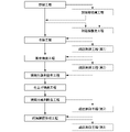
- 1 is a flow chart showing a method of manufacturing a grain-oriented electrical steel sheet according to an embodiment of the present invention.
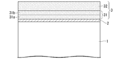
- FIG. 1 is a schematic cross-sectional view showing the layer structure of a grain-oriented electrical steel sheet according to one embodiment of the present invention.
- the grain-oriented electrical steel sheet according to the present embodiment has no forsterite coating on the surface of the base material steel sheet 1 when viewed on a cut plane whose cutting direction is parallel to the thickness direction.
- a material steel plate 1 has an intermediate layer 2 mainly composed of silicon oxide on the surface thereof, and has an insulating coating 3 derived from phosphate and colloidal silica on the intermediate layer 2 .
- the grain-oriented electrical steel sheet according to the present embodiment is A base material steel plate that is a silicon steel plate, an intermediate layer disposed in contact with the silicon steel plate; and an insulating coating disposed in contact with the intermediate layer,
- the intermediate layer is Si content: 20 atomic % or more and 70 atomic % or less, O content: 30 atomic % or more and 80 atomic % or less, Mg content: less than 20 atomic %, P content: less than 5 atomic %, Fe content: less than 20 atomic %, is an oxide film that satisfies
- the insulating coating is P content: 5 atomic % or more and 30 atomic % or less, Si content: 5 atomic % or more and 30 atomic % or less, O content: 30 atomic % or more and 80 atomic % or less, Fe content: 1 atomic % or more and less than 25 atomic %, Cr content: less than 1.0 atomic %, Al content: 0 atomic % or more and 10 atomic
- the intermediate layer is not the forsterite coating but the Si-based oxide film
- the insulating coating is the phosphoric acid-based coating
- the phosphoric acid-based coating has the first and a second crystalline phosphorous oxide.
- the phosphoric acid-based coating is positioned on the outermost surface of the layer structure of the grain-oriented electrical steel sheet.
- This phosphoric acid coating is formed on the base steel plate in a high-temperature environment using a substance with a smaller thermal expansion coefficient than the base steel plate, so the phosphoric acid coating and the base steel plate contract during cooling. A difference occurs, and as a result, the phosphoric acid-based coating imparts tension to the base steel sheet.
- a grain-oriented electrical steel sheet in which tension is applied to the base material steel sheet is preferably improved in iron loss characteristics.
- the phosphate coating In order for the phosphate coating to impart tension to the base steel plate, it is important that the phosphate coating and the base steel plate are in close contact.
- the coating composition and thickness of the phosphoric acid-based coating are controlled, and the phosphoric acid-based coating contains multiple types of crystalline phosphates.
- the phosphoric acid-based coating contains basic elements and, if necessary, optional elements as a coating composition. Moreover, it is preferable that the remainder of the basic elements and the selective elements consist of impurities.
- the phosphoric acid-based coating contains, as a basic element, P content: 5 atomic % or more and 30 atomic % or less, Si content: 5 atomic % or more and 30 atomic % or less, O content: 30 atomic % or more and 80 atomic % or less, and Fe content: 1 atomic % or more and less than 25 atomic %, should be satisfied.
- the phosphoric acid-based coating as a selective element, Al content: 0 atomic % or more and 10 atomic % or less, Mg content: 0 atomic % or more and 10 atomic % or less, Mn content: 0 atomic % or more and 10 atomic % or less, Ni content: 0 atomic % or more and 10 atomic % or less, Zn content: 0 atomic % or more and 10 atomic % or less Total content of Al + Mg + Mn + Ni + Zn: 0.1 atomic % or more and 10 atomic % or less, V content: 0 atomic % or more and 10 atomic % or less, W content: 0 atomic % or more and 10 atomic % or less, Zr content: 0 atomic % or more and 10 atomic % or less, Co content: 0 atomic % or more and 10 atomic % or less, Mo content: 0 atomic % or more and 10 atomic % or less, Total
- the phosphate-based coating of grain-oriented electrical steel sheets is formed by baking a coating solution containing phosphate, colloidal silica, and chromate. This chromate is added for improving corrosion resistance, improving chemical resistance, and suppressing voids.
- the phosphoric acid-based coating of the grain-oriented electrical steel sheet according to the present embodiment is formed by baking a coating solution that contains phosphate and colloidal silica but does not contain chromate. Therefore, as described above, the Cr content in the phosphoric acid-based coating of the grain-oriented electrical steel sheet according to the present embodiment is limited to less than 1.0 atomic percent.
- the Cr content is preferably 0.8 atomic % or less, more preferably 0.5 atomic % or less.
- limiting the Cr content of the phosphoric acid-based coating to less than 1.0 atomic % allows the above-described first crystalline phosphate and This is one of the control conditions for forming the crystalline phosphorous oxide of No. 2. The details of the conditions for forming these crystalline phosphorous oxides will be described later.
- P, Si, O, and Fe which are the basic elements of the phosphoric acid-based coating, diffuse from the phosphate and colloidal silica contained in the coating solution, the oxidation reaction during baking heat treatment, and the base steel plate.
- Al, Mg, Mn, Ni, Zn, V, W, Zr, Co, and Mo which are selective elements for the phosphoric acid coating, are derived from the phosphate contained in the coating solution.
- at least one phosphate selected from Al, Mg, Mn, Ni, Zn, V, W, Zr, Co, and Mo may be used as the phosphate contained in the coating solution.
- At least one phosphate selected from Al, Mg, Mn, Ni, and Zn is used as the phosphate contained in the coating solution, and the phosphate-based coating has a coating composition of The total content of Al+Mg+Mn+Ni+Zn: 0.1 atomic % or more and 10 atomic % or less may be satisfied.
- aluminum phosphate may be used as the phosphate contained in the coating solution, and the phosphoric acid-based coating may satisfy an Al content of 0.1 atomic % or more and 10 atomic % or less as the coating composition.
- the phosphate contained in the coating solution at least one phosphate selected from Co, Mo, V, W, and Zr is used, and the phosphate-based coating has a coating composition of V + W + Zr + Co + Mo total content: 0.1 atomic % or more and 10 atomic % or less.
- the above-mentioned Cr is an impurity in the phosphoric acid-based coating, and these impurities originate from elements mixed from the raw material or manufacturing environment when forming the phosphoric acid-based coating, or elements diffused from the base steel sheet.
- the lower limit of the content of impurities is not particularly limited, and the lower the better, so it may be 0%.
- the film composition of the phosphoric acid-based film should satisfy the above conditions in order to improve the film adhesion.
- the Cr content of the phosphoric acid-based coating is limited to less than 1.0 atomic percent.
- the P content is preferably more than 8 atomic % and less than 17 atomic % as the film composition (average film composition) of the phosphoric acid-based film.
- the Si content is more than 7 atomic %, preferably less than 19 atomic %
- the O content is preferably more than 58 atomic %, preferably less than 66 atomic %.
- the Fe content is greater than 1 atomic %, preferably less than 20 atomic %
- the Cr content is preferably less than 0.2 atomic %
- the Al content is preferably less than 10 atomic %.
- Mg content is preferably less than 10 atomic %, preferably less than 3 atomic %
- Mn content is preferably less than 10
- the Ni content is preferably less than 10 atomic %, preferably less than 3 atomic %
- the Zn content is 10
- the total content of Al + Mg + Mn + Ni + Zn is preferably 0.1 atomic % or more, preferably more than 1 atomic %, and 10 atomic % %, preferably less than 3 atomic %
- the V content is preferably less than 3.0 atomic %, preferably less than 2 atomic %
- the W content is It is preferably less than 3.0 atomic %, preferably less than 2 atomic %
- Zr content is preferably less than 3.0 atomic %, preferably
- the coating composition of the phosphoric acid-based coating can be analyzed by SEM-EDS (Scanning Electron Microscope-Energy Dispersive X-ray Spectroscopy) or TEM-EDS (Transmission Electron Microscope-Energy Dispersive X-ray Spectroscopy) if the composition is analyzed using the cutting surface. good. The details of the method for measuring the coating composition will be described later.
- the average film thickness of the phosphoric acid-based coating is 0.1 ⁇ m or more and 10 ⁇ m or less when viewed on a cut surface whose cutting direction is parallel to the plate thickness direction.
- the average thickness of the phosphoric acid-based coating is less than 0.1 ⁇ m, it becomes difficult to apply the required tension to the base steel sheet. The above is more preferable.
- the average thickness of the phosphoric acid-based coating exceeds 10 ⁇ m, cracks may occur in the phosphoric acid-based coating during the formation of the phosphoric acid-based coating. 5 ⁇ m or less is more preferable.
- the average film thickness of the phosphoric acid-based coating can be obtained by line analysis of the cut surface using SEM-EDS or TEM-EDS. The details of the method for measuring the average film thickness will be described later.
- the first crystalline phosphorous oxide having a crystal structure corresponding to Fe 2 P 2 O 7 and the crystal structure Fe 7 (P 2 O 7 ) and a second crystalline phosphorous oxide corresponding to 4 .
- the coating adhesion is improved.
- the presence of crystalline phosphorous oxide in the amorphous phosphoric acid-based coating increases the overall elasticity of the phosphoric acid-based coating. It is thought that the stress accumulated in the film is relieved without being locally concentrated, and as a result, the phosphoric acid-based coating becomes difficult to peel off. In particular, it is believed that the second crystalline phosphorous oxide exhibits the above effect remarkably.
- the intermediate layer is not a forsterite film but a Si-based oxide film.
- the phosphoric acid-based coating should satisfy a Cr content of less than 1.0 atomic percent as the coating composition.
- III Control the formation conditions when forming the phosphoric acid-based coating. Both the first crystalline phosphorous oxide and the second crystalline phosphorous oxide are formed in the phosphoric acid-based coating only when all of these three conditions are satisfied.
- the intermediate layer is not a forsterite film but a Si-based oxide film. If the intermediate layer is a forsterite coating, the problem of coating adhesion does not exist in the first place, and crystalline phosphorous oxide is not formed in the phosphoric acid-based coating.
- condition (II) it is important that the Cr content be less than 1.0 atomic % as the film composition of the phosphoric acid-based film. If the Cr content of the phosphoric acid-based coating is 1.0 atomic % or more, even if the first crystalline phosphorous oxide is formed in the phosphoric acid-based coating, the second crystalline phosphorous No oxides are formed.
- the reason why the second crystalline phosphorous oxide is not formed in the phosphoric acid-based coating when the Cr content of the phosphoric acid-based coating is 1.0 atomic % or more is currently unknown, but the following Possible cause. If the Cr content of the phosphoric acid-based coating is 1.0 atomic % or more, (Fe, Cr) 2 P 2 O 7 is formed in the phosphoric acid-based coating. This (Fe, Cr) 2 P 2 O 7 tends to be preferentially formed.
- condition (III) it is important to control the formation conditions during the formation of the phosphoric acid coating. Even if the conditions (I) and (II) are satisfied, if the formation conditions are not suitably controlled during the formation of the phosphoric acid-based coating, the phosphoric acid-based coating will contain crystalline phosphorous oxides, especially secondary crystals. Phosphorus oxides are not formed.
- the presence of the first crystalline phosphorous oxide and the second crystalline phosphorous oxide may be confirmed using TEM.
- electron beam diffraction is performed on the phosphoric acid-based coating, the crystal structure of the crystalline phase contained in the electron beam irradiation region is identified from the electron beam diffraction pattern, and the crystal structure corresponds to Fe 2 P 2 O 7 . 1 and a second crystalline phosphorous oxide whose crystal structure corresponds to that of Fe 7 (P 2 O 7 ) 4 are confirmed.
- the details of the identification method of the crystalline phosphorous oxide will be described later.
- the phosphoric acid-based coating contains both the first crystalline phosphorous oxide and the second crystalline phosphorous oxide, the coating adhesion is improved. Therefore, the composition, form, and size of the crystalline phosphorous oxide are not particularly limited. However, in order to favorably improve film adhesion, it is preferable that the composition, form, and size of the crystalline phosphorous oxide have the following characteristics.
- the phosphoric acid-based coating satisfies, as a coating composition, a total content of V + W + Zr + Co + Mo: 0.1 atomic % or more and 10 atomic % or less, and the second crystalline phosphoric oxide, At least one selected from the group consisting of V, W, Zr, Co, and Mo is preferably included.
- Fe 7 (P 2 (Fe, M) 7 ( P 2 O 7 ) 4 is likely to be formed as the second crystalline phosphorous oxide having the O 7 ) 4 structure.
- M is at least one selected from the group consisting of V, W, Zr, Co and Mo.
- V, W, Zr, Co, or Mo contained in the phosphoric acid-based coating as a coating composition emits an electron beam to this deposit, for example.
- elemental analysis is performed by irradiation, it is detected as a peak corresponding to the element in the EDS spectrum. be.
- the number of the second crystalline phosphorous oxides formed increases, and the effect of each formed second crystalline phosphorous oxide on the film adhesion also preferably increases. As a result, the film adhesion is favorably improved.
- the phosphoric acid-based coating when viewed on a cut plane whose cutting direction is parallel to the plate thickness direction, is divided into the inner region in contact with the oxide film and the inner region in contact with the oxide film.
- the surface region is divided into two equal parts, the first crystalline phosphorous oxide contained in the inner region is smaller than the total area ratio of the first crystalline phosphorous oxide and the second crystalline phosphorous oxide contained in the surface region. It is preferable that the total area ratio of the oxide and the second crystalline phosphorous oxide is large.
- the overall elasticity of the phosphoric acid-based coating is preferably increased. Therefore, it is considered that the stress is preferably relaxed under the bending stress, and as a result, the phosphoric acid-based coating becomes difficult to peel off.
- the total area ratio of the first crystalline phosphorylated oxide and the second crystalline phosphorous oxide contained in the surface region is 0% or more and 30% or less, and the first crystalline phosphorylated oxide contained in the inner region
- the total area ratio of the substance and the second crystalline phosphorous oxide is preferably 3% or more and 50% or less.
- the first crystalline phosphorous oxide and the second crystalline phosphorous oxide are contained more in the inner region than in the surface region in the phosphoric acid-based coating, and the first crystalline phosphoric oxide and the second crystalline phosphoric oxide When the total area ratio of the phosphoric oxides is within the above range, the overall elasticity of the phosphoric acid-based coating is more preferably increased, and the coating adhesion is more preferably improved.
- the internal region when viewed on a cut surface whose cutting direction is parallel to the plate thickness direction, the internal region is divided into the first internal region in contact with the oxide film and the oxide film and a second inner region that does not touch the
- the area ratio of the second crystalline phosphorous oxide contained in the first internal region is defined as the total area ratio of the first crystalline phosphorous oxide and the second crystalline phosphorous oxide contained in the first internal region.
- the percentage of the value divided by is the first area ratio
- the area ratio of the second crystalline phosphorous oxide contained in the second internal region is defined as the total area ratio of the first crystalline phosphorous oxide and the second crystalline phosphorous oxide contained in the second internal region.
- the second area ratio is preferably larger than the first area ratio.
- the overall elasticity of the phosphate-based coating preferably increases, and under bending stress It is thought that the stress is favorably relieved at , and as a result, the phosphoric acid-based coating becomes difficult to peel off.
- the first area ratio is 0% or more and 70% or less
- the second area ratio is 50% or more and 100% or less.
- the entire phosphoric acid-based coating contains more of the second crystalline phosphorous oxide than the first inner region in the inner region, and the second area ratio is within the above range, the entire phosphoric acid-based coating
- the elastic elasticity is further preferably increased, and the film adhesion is further preferably improved.
- FIG. 2 is a schematic cross-sectional view showing the layer structure of a grain-oriented electrical steel sheet according to a preferred embodiment of the present invention.
- FIG. 2 illustrates the surface region 32, internal region 31, first internal region 31a, and second internal region 31b of the phosphoric acid coating 3 (insulating coating 3).
- the equivalent circle diameter of the second crystalline phosphorous oxide is preferably 5 nm or more and 300 nm or less on average.
- the equivalent circle diameter of the second crystalline phosphorous oxide is preferably 20 nm or more, and preferably 220 nm or less.
- oxide film that is the intermediate layer of the grain-oriented electrical steel sheet according to this embodiment will be described.
- the oxide film is located between the phosphoric acid coating and the base steel sheet on the layer structure of the grain-oriented electrical steel sheet.
- This oxide film is not a forsterite film but a Si-based oxide film, and has a function of adhering the phosphoric acid-based film and the base steel plate.
- the oxide film contains basic elements as a coating composition. Moreover, in addition to the basic elements, optional elements may be included as necessary. Moreover, it is preferable that the remainder of the basic elements and the selective elements consist of impurities.
- the oxide film contains, as a basic element, Si content: 20 atomic % or more and 70 atomic % or less, and O content: 30 atomic % or more and 80 atomic % or less, should be satisfied.
- the oxide film may contain constituent elements of the base steel sheet as selective elements, and the total content thereof may satisfy 0.1 atomic % or more and 20 atomic % or less.
- the oxide film as an impurity, Mg content: less than 20 atomic %, P content: less than 5 atomic %, and Fe content: less than 20 atomic %, should be satisfied.
- a forsterite coating (mainly composed of Mg 2 SiO 4 coating) is formed.
- the interface between the intermediate layer and the base steel sheet is intended to be smooth without the presence of the forsterite coating.
- the above conditions (I) to (III) are satisfied, and the first crystalline phosphorous oxide and the second of crystalline phosphorous oxide.
- the intermediate layer must be controlled to be a Si-based oxide film instead of a forsterite film.
- the Mg content is limited to less than 20 atomic %.
- the Mg content is preferably 15 atomic % or less, more preferably 10 atomic % or less.
- the basic elements of the oxide film Si and O, are derived from the constituent elements of the base steel sheet and from the oxidation reaction when the oxide film is formed.
- Mg, P, and Fe described above are impurities of the oxide film, and these impurities originate from elements mixed from the raw material or the manufacturing environment, or elements diffused from the base steel sheet or the phosphoric acid coating.
- the lower limit of the content of impurities is not particularly limited, and the lower the better, so it may be 0%.
- the Si content is preferably more than 26 atomic %, preferably less than 44 atomic %, as the film composition (average film composition) of the oxide film.
- the O content is preferably greater than 38 atomic %, preferably less than 68 atomic %, the Mg content is preferably less than 20 atomic %, and the P content is less than 5 atomic %. or the Fe content is preferably less than 20 atomic %.
- the film composition of the oxide film can be obtained by analyzing the composition of the cut surface using SEM-EDS or TEM-EDS in the same manner as the film composition of the phosphoric acid-based film. The details of the method for measuring the coating composition will be described later.
- the average film thickness of the oxide film is 2 nm or more and 500 nm or less when viewed on a cut surface whose cutting direction is parallel to the plate thickness direction.
- the average film thickness of the oxide film is less than 2 nm, the effect of relieving thermal stress is not sufficiently exhibited, so the average film thickness is preferably 2 nm or more, more preferably 5 nm or more.
- the average thickness of the oxide film exceeds 500 nm, the thickness becomes non-uniform and defects such as voids and cracks occur in the layer. is more preferred.
- the average film thickness of the oxide film can be obtained by line analysis of the cut surface using SEM-EDS or TEM-EDS, similar to the film composition of the phosphoric acid-based film. The details of the method for measuring the average film thickness will be described later.
- a base material steel plate is a base material of a grain-oriented electrical steel plate, and is a silicon steel plate.
- the silicon steel sheet should have a Si content of 0.8% by mass or more and 7.0% by mass or less, and the crystal orientation should be controlled to the ⁇ 110 ⁇ 001> orientation (Goss orientation).
- the ⁇ 110 ⁇ 001> orientation means that the ⁇ 110 ⁇ plane of the crystal is parallel to the rolling plane and the ⁇ 001> axis of the crystal is parallel to the rolling direction.
- the steel composition of the silicon steel sheet is not directly related to the presence of the first crystalline phosphorous oxide and the second crystalline phosphorous oxide in the phosphoric acid-based coating.
- the steel composition of the steel plate is not particularly limited. However, the steel composition of a silicon steel sheet that is preferable as a grain-oriented electrical steel sheet will be described below.
- % relating to the steel composition of the silicon steel sheet means % by mass.
- the silicon steel sheet contain, as chemical components, basic elements, optional elements as necessary, and the remainder consisting of Fe and impurities.
- the silicon steel sheet is mass%, Si: 0.8% or more and 7.0% or less, Mn: 0 or more and 1.00% or less, Cr: 0 or more and 0.30% or less, Cu: 0 or more and 0.40% or less, P: 0 or more and 0.50% or less, Sn: 0 or more and 0.30% or less, Sb: 0 or more and 0.30% or less, Ni: 0 or more and 1.00% or less, B: 0 or more and 0.008% or less, V: 0 or more and 0.15% or less, Nb: 0 or more and 0.2% or less, Mo: 0 or more and 0.10% or less, Ti: 0 or more and 0.015% or less, Bi: 0 or more and 0.010% or less, Al: 0 or more and 0.005% or less, C: 0 or more and 0.005% or less, N: 0 or more and 0.005% or less, S: 0 or more and 0.005% or less, Se
- the silicon steel sheet should contain Si as a basic element (main alloying element).
- Si 0.8% or more and 7.0% or less
- Si is an element effective in increasing electrical resistance and reducing iron loss as a chemical component of a silicon steel sheet. If the Si content exceeds 7.0%, the material tends to crack during cold rolling, making rolling difficult. On the other hand, when the Si content is less than 0.8%, the electrical resistance becomes small and the iron loss in the product may increase. Therefore, Si may be contained in the range of 0.8% or more and 7.0% or less.
- the lower limit of the Si content is preferably 2.0%, more preferably 2.5%, even more preferably 2.8%.
- the upper limit of the Si content is preferably 5.0%, more preferably 3.5%.
- the silicon steel sheet may contain impurities.
- impurities refers to substances mixed from ores and scraps used as raw materials or from the manufacturing environment or the like during the industrial production of steel.
- the silicon steel sheet may contain selective elements in addition to the basic elements and impurities described above.
- selective elements Mn, Cr, Cu, P, Sn, Sb, Ni, B, V, Nb, Mo, Ti, Bi, Al, C, N , S, and Se.
- These selective elements may be contained depending on the purpose. Therefore, it is not necessary to limit the lower limit of these selective elements, and the lower limit may be 0%. Moreover, even if these selective elements are contained as impurities, the above effect is not impaired.
- Mn 0 to 1.00% Mn (manganese), like Si, is an element effective in increasing electrical resistance and reducing iron loss. It also functions as an inhibitor by binding with S or Se. Therefore, Mn may be contained in the range of 1.00% or less.
- the lower limit of the Mn content is preferably 0.05%, more preferably 0.08%, even more preferably 0.09%.
- the upper limit of the Mn content is preferably 0.50%, more preferably 0.20%.
- Cr 0 to 0.30% Cr (chromium), like Si, is an element effective in increasing electric resistance and reducing iron loss. Therefore, Cr may be contained in the range of 0.30% or less.
- the lower limit of the Cr content is preferably 0.02%, more preferably 0.05%.
- the upper limit of the Cr content is preferably 0.20%, more preferably 0.12%.
- Cu is also an effective element for increasing electrical resistance and reducing iron loss. Therefore, Cu may be contained in the range of 0.40% or less. If the Cu content exceeds 0.40%, the effect of reducing iron loss is saturated and may cause surface defects called "copper scab" during hot rolling.
- the lower limit of the Cu content is preferably 0.05%, more preferably 0.10%.
- the upper limit of the Cu content is preferably 0.30%, more preferably 0.20%.
- P 0 to 0.50%
- P is also an effective element for increasing electric resistance and reducing iron loss. Therefore, P may be contained in the range of 0.50% or less. If the P content exceeds 0.50%, problems may arise in the rollability of the silicon steel sheet.
- the lower limit of the P content is preferably 0.005%, more preferably 0.01%.
- the upper limit of the P content is preferably 0.20%, more preferably 0.15%.
- Sn 0 to 0.30%
- Sb 0 to 0.30%
- Sn (tin) and Sb (antimony) stabilize secondary recrystallization and develop the ⁇ 110 ⁇ 001> orientation. It is an effective element. Therefore, Sn may be contained in the range of 0.30% or less, and Sb may be contained in the range of 0.30% or less. If the Sn or Sb content exceeds 0.30%, the magnetic properties may be adversely affected.
- the lower limit of the Sn content is preferably 0.02%, more preferably 0.05%.
- the upper limit of the Sn content is preferably 0.15%, more preferably 0.10%.
- the lower limit of the Sb content is preferably 0.01%, more preferably 0.03%.
- the upper limit of the Sb content is preferably 0.15%, more preferably 0.10%.
- Ni 0 to 1.00%
- Ni nickel
- Ni is also an effective element for increasing electric resistance and reducing iron loss.
- Ni is an element effective in controlling the metal structure of the hot-rolled sheet and enhancing the magnetic properties. Therefore, Ni may be contained in the range of 1.00% or less. If the Ni content exceeds 1.00%, secondary recrystallization may become unstable.
- the lower limit of the Ni content is preferably 0.01%, more preferably 0.02%.
- the upper limit of the Ni content is preferably 0.20%, more preferably 0.10%.
- B 0 to 0.008%
- B is an element effective in exhibiting an inhibitory effect as BN. Therefore, B may be contained in the range of 0.008% or less. If the B content exceeds 0.008%, the magnetic properties may be adversely affected.
- the lower limit of the B content is preferably 0.0005%, more preferably 0.001%.
- the upper limit of the B content is preferably 0.005%, more preferably 0.003%.
- V 0 to 0.15%
- Nb 0 to 0.2%
- Ti 0 to 0.015%
- V vanadium
- Nb niobium
- Ti titanium
- the V content may be 0.15% or less
- the Nb content may be 0.2% or less
- the Ti content may be 0.015% or less.
- the lower limit of the V content is preferably 0.002%, more preferably 0.01%.
- the upper limit of the V content is preferably 0.10% or less, more preferably 0.05%.
- the lower limit of the Nb content is preferably 0.005%, more preferably 0.02%.
- the upper limit of the Nb content is preferably 0.1%, more preferably 0.08%.
- the lower limit of the Ti content is preferably 0.002%, more preferably 0.004%.
- the upper limit of the Ti content is preferably 0.010%, more preferably 0.008%.
- Mo 0 to 0.10%
- Mo molybdenum
- Mo is also an effective element for increasing electric resistance and reducing iron loss. Therefore, Mo may be contained in the range of 0.10% or less. If the Mo content exceeds 0.10%, problems may arise in the rollability of the steel sheet.
- the lower limit of the Mo content is preferably 0.005%, more preferably 0.01%.
- the upper limit of the Mo content is preferably 0.08%, more preferably 0.05%.
- Bi 0 to 0.010%
- Bi bismuth
- Bi is an element effective in stabilizing precipitates such as sulfides and strengthening the function as an inhibitor. Therefore, Bi may be contained in the range of 0.010% or less. If the Bi content exceeds 0.010%, the magnetic properties may be adversely affected.
- the lower limit of the Bi content is preferably 0.001%, more preferably 0.002%.
- the upper limit of the Bi content is preferably 0.008%, more preferably 0.006%.
- Al 0 to 0.005%
- Al is an element effective in exhibiting an inhibitory effect by bonding with N. Therefore, Al may be contained in the range of 0.01 to 0.065% before finish annealing, for example, at the slab stage.
- the Al content of the final product is preferably 0.005% or less.
- the upper limit of the Al content in the final product is preferably 0.004%, more preferably 0.003%.
- the Al content of the final product is an impurity, and the lower limit is not particularly limited, and the lower the better. However, since it is industrially not easy to make the Al content of the final product 0%, the lower limit of the Al content of the final product may be more than 0% or 0.0005%.
- Al content shows content of acid-soluble Al.
- C is an effective element for adjusting the primary recrystallization texture and enhancing the magnetic properties.
- N nitrogen
- C may be contained in the range of 0.02 to 0.10% before decarburization annealing, for example, in the slab stage.
- N may be contained in the range of 0.01 to 0.05% before finish annealing, for example, after nitriding annealing.
- these elements remain as impurities in the final product and each of C and N exceeds 0.005%, the magnetic properties may be adversely affected.
- each of C and N in the final product is preferably 0.005% or less.
- Each of C and N in the final product is preferably 0.004% or less, more preferably 0.003% or less.
- the total content of C and N in the final product is preferably 0.005% or less.
- C and N in the final product are impurities, and their content is not particularly limited, and the smaller the better. However, since it is industrially difficult to make the C and N contents of the final product 0%, respectively, the C and N contents of the final product may each exceed 0%. 0005% or more.
- S 0 or more and 0.005% or less
- Se 0 to 0.005%
- S (sulfur) and Se (selenium) are elements effective in exhibiting an inhibitor effect by bonding with Mn or the like. Therefore, S and Se may each be contained in the range of 0.005 to 0.050% before finish annealing, for example, at the slab stage. However, if these elements remain as impurities in the final product and each of S and Se exceeds 0.005%, the magnetic properties may be adversely affected. Therefore, S and Se in the final product are each preferably 0.005% or less. Each of S and Se in the final product is preferably 0.004% or less, more preferably 0.003% or less.
- the total content of S and Se in the final product is preferably 0.005% or less.
- S and Se in the final product are impurities, and their contents are not particularly limited, and the smaller the better. However, since it is industrially not easy to make the S and Se contents of the final product 0%, the S and Se contents of the final product may each exceed 0%. 0005% or more.
- the silicon steel sheet contains, as selected elements, Mn: 0.05% or more and 1.00% or less, Cr: 0.02% or more and 0.30% or less, and Cu: 0.05% or more by mass%. 0.40% or less, P: 0.005% or more and 0.50% or less, Sn: 0.02% or more and 0.30% or less, Sb: 0.01% or more and 0.30% or less, Ni: 0.01 % or more and 1.00% or less, B: 0.0005% or more and 0.008% or less, V: 0.002% or more and 0.15% or less, Nb: 0.005% or more and 0.2% or less, Mo: 0 .005% or more and 0.10% or less, Ti: 0.002% or more and 0.015% or less, and Bi: 0.001% or more and 0.010% or less.
- Mn 0.05% or more and 1.00% or less
- Cr 0.02% or more and 0.30% or less
- Cu 0.05% or more by mass%.
- P 0.005% or more and
- the chemical composition of the silicon steel sheet can be measured by a general analytical method. The details of the method for measuring the steel composition will be described later.
- the silicon steel sheet preferably has a texture developed in the ⁇ 110 ⁇ 001> orientation. Magnetic properties are preferably improved by controlling the silicon steel sheet to have a Goss orientation.
- the thickness of the silicon steel sheet is not particularly limited, the average thickness is preferably 0.35 mm or less, more preferably 0.30 mm or less, in order to further reduce iron loss.
- the lower limit of the thickness of the silicon steel sheet is not particularly limited, it may be 0.10 mm from the viewpoint of manufacturing equipment and cost.
- the surface roughness of the silicon steel sheet (the roughness of the interface between the intermediate layer and the base steel sheet) is preferably smooth.
- the surface roughness of the silicon steel sheet is preferably 0.5 ⁇ m or less, more preferably 0.3 ⁇ m or less in terms of arithmetic mean roughness (Ra).
- the lower limit of the arithmetic mean roughness (Ra) of the base steel sheet is not particularly limited, but if it is 0.1 ⁇ m or less, the iron loss improvement effect becomes saturated, so the lower limit may be 0.1 ⁇ m.
- the grain-oriented electrical steel sheet according to the present embodiment has excellent coating adhesion even without the forsterite coating. Therefore, iron loss characteristics are favorably improved.
- the layer structure of the grain-oriented electrical steel sheets described above may be specified, for example, by the following method.
- a test piece is cut from the grain-oriented electrical steel sheet, and the layer structure of the test piece is observed with a scanning electron microscope (SEM) or a transmission electron microscope (TEM).
- SEM scanning electron microscope
- TEM transmission electron microscope
- a layer with a thickness of 300 nm or more may be observed with an SEM, and a layer with a thickness of less than 300 nm may be observed with a TEM.
- a test piece is cut so that the cutting direction is parallel to the plate thickness direction (more specifically, the test piece is cut so that the cut surface is parallel to the plate thickness direction and perpendicular to the rolling direction. cutting), and the cross-sectional structure of this cut surface is observed with an SEM at a magnification that allows each layer to be included in the observation field.
- SEM backscattered electron composition image
- the base material steel sheet can be distinguished as a light color, the intermediate layer as a dark color, and the insulation coating as a neutral color.
- SEM-EDS is used to perform line analysis along the plate thickness direction and quantitatively analyze the chemical components of each layer. For example, five elements of Fe, P, Si, O, and Mg are quantitatively analyzed.
- the device to be used is not particularly limited. ESPRIT 1.9) manufactured by the company may be used.
- the Fe content is less than 80 atomic%, and the P content is 5 atomic%.
- the Si content is 5 atomic % or more and the O content is 30 atomic % or more, and the line segment (thickness) on the scanning line of the line analysis corresponding to this region is 300 nm or more , this region is determined to be a phosphoric acid coating.
- the phosphate-based coating contains the above-described selective elements such as aluminum, magnesium, nickel, and manganese derived from phosphate. may be
- the precipitates, inclusions, and pores contained in the coating are not included in the determination target, and the matrix satisfies the above quantitative analysis results.
- the area is judged to be a phosphoric acid coating. For example, if it is confirmed from the COMPO image and line analysis results that there are precipitates, inclusions, and vacancies on the scanning line of the line analysis, the result of quantitative analysis as the mother phase without including this region Judging by Precipitates, inclusions, and vacancies can be distinguished from the matrix phase by the contrast in the COMPO image, and can be distinguished from the matrix phase by the abundance of constituent elements in the quantitative analysis results.
- this region is the intermediate layer We judge that it is.
- the intermediate layer should satisfy Fe content of less than 80 atomic percent, P content of less than 5 atomic percent, Si content of 20 atomic percent or more, and O content of 30 atomic percent or more. Also, if the intermediate layer is not a forsterite coating but an oxide film mainly composed of silicon oxide, the content of Mg in the intermediate layer should be less than 20 atomic %.
- the results of quantitative analysis of the intermediate layer are the results of quantitative analysis of the parent phase, excluding the results of analysis of precipitates, inclusions, pores, and the like contained in the intermediate layer. When identifying the intermediate layer, it is preferable to identify it at a position that does not include precipitates, inclusions, and voids on the scanning line of the line analysis.
- the above COMPO image observation and SEM-EDS quantitative analysis to identify each layer and measure the thickness are carried out at 5 or more locations by changing the observation field. About the thickness of each layer obtained at a total of five or more locations, the average value is obtained from the values excluding the maximum value and the minimum value, and this average value is taken as the average thickness of each layer.
- a layer having a line segment (thickness) of less than 300 nm on the line analysis scanning line exists in at least one of the five or more observation fields described above, the corresponding layer is observed in detail with a TEM. Then, a TEM is used to identify and measure the thickness of the layer in question.
- a test piece containing layers to be observed in detail using a TEM is cut out by FIB (Focused Ion Beam) processing so that the cutting direction is parallel to the plate thickness direction (more specifically, the cut surface is parallel to the plate thickness direction).
- a test piece is cut out so that it is parallel and perpendicular to the rolling direction), and the cross-sectional structure of this cut surface is observed with STEM (Scanning-TEM) at a magnification in which the corresponding layer is included in the observation field (bright field image). . If each layer does not fall within the observation field of view, the cross-sectional structure is observed in a plurality of continuous fields of view.
- TEM-EDS is used to perform line analysis along the plate thickness direction and perform quantitative analysis of the chemical components of each layer. Five elements of Fe, P, Si, O and Mg are to be quantitatively analyzed.
- the device to be used is not particularly limited, for example, TEM (JEM-2100F manufactured by JEOL Ltd.), EDS (JED-2300T manufactured by JEOL Ltd.), EDS analysis software (AnalysisStation manufactured by JEOL Ltd.) can be used. good.
- each layer is specified and the average film thickness of each layer is measured.
- the method of specifying each layer using TEM and the method of measuring the average film thickness of each layer may be carried out according to the above-described method using SEM.
- each layer specified by TEM is 5 nm or less
- a TEM having a spherical aberration correction function is used from the viewpoint of spatial resolution.
- point analysis is performed at intervals of, for example, 2 nm or less along the plate thickness direction, the line segment (film thickness) of each layer is measured, and this line segment is the film of each layer.
- thickness may be used.
- EDS analysis can be performed with a spatial resolution of about 0.2 nm.
- an oxide film exists in contact with the base steel sheet, and a phosphoric acid-based coating exists in contact with the oxide film.
- a phosphoric acid-based coating exists in contact with the oxide film.
- the film composition of the phosphoric acid-based coating and the oxide film may be quantitatively analyzed in detail using SEM-EDS or TEM-EDS within the region of the phosphoric acid-based coating and oxide film specified above. For this quantitative analysis, line analysis or point analysis may be performed at multiple points within the target area. Further, when quantitatively analyzing the film composition, the elements to be quantitatively analyzed are not the five elements of Fe, P, Si, O, and Mg, but all the elements to be quantitatively analyzed. For the film composition of the phosphoric acid-based coating and the oxide film, the average composition may be obtained within the regions of the phosphoric acid-based coating and the oxide film specified above.
- a first crystalline phosphorous oxide having a crystal structure corresponding to Fe 2 P 2 O 7 and a crystal structure corresponding to Fe 7 (P 2 O 7 ) 4 The following method may be used to determine whether or not the second crystalline phosphorous oxide is included.
- the test piece containing the phosphoric acid coating is cut out by FIB processing so that the cutting direction is parallel to the plate thickness direction (specifically, the cut surface is in the plate thickness direction A test piece is cut out parallel to and perpendicular to the rolling direction), and the cross-sectional structure of this cut surface is observed with a TEM at a magnification that allows the phosphoric acid coating to enter the observation field.
- Wide-area electron beam diffraction is performed on the phosphoric acid coating in the observation field with an electron beam diameter of 1/10 of the phosphoric acid coating or 200 nm, whichever is smaller, and some crystalline phase is detected in the electron beam irradiation region. Existence of is confirmed from the electron beam diffraction pattern.
- the chemical composition of the target crystalline phase is that the total content of Fe, P, and O is 70 atomic % or more and 100 atomic % or less, and Si is 10 atomic % or less. If so, it can be determined to be a crystalline and phosphorus-containing phase, and this crystalline phase is determined to be a crystalline phosphorous oxide.
- electron beam diffraction is performed with the electron beam narrowed down so that information can be obtained only from the target crystalline phase, and the target crystalline phase is analyzed from the electron diffraction pattern. to identify the crystal structure of the crystalline phase. This identification may be performed using the PDF (Powder Diffraction File) of the ICDD (International Center for Diffraction Data).
- the crystalline phase is the first crystalline phosphorous oxide having the Fe 2 P 2 O 7 structure or the first crystalline phosphorous oxide having the Fe 7 (P 2 O 7 ) 4 structure. 2 crystalline phosphorous oxide.
- identification of whether or not the crystalline phase has the Fe 2 P 2 O 7 structure refer to PDF:No. 01-072-1516. Further, identification of whether or not the crystalline phase has the Fe 7 (P 2 O 7 ) 4 structure is described in PDF:No. 01-079-2259. When the crystalline phase is identified based on the above PDF, the identification may be performed with a tolerance of ⁇ 5% for the interplanar spacing and ⁇ 3° for the interplanar angle.
- the area ratio of crystalline phosphorous oxide can be obtained as follows. For example, by the above method, the first crystalline phosphorous oxide and the second crystalline phosphorous oxide are specified, the specified crystalline phosphorous oxide and the matrix are binarized, and the crystalline phosphorous oxide is analyzed by image analysis. It suffices to obtain the area ratio of the oxide. For example, the area ratio of the first crystalline phosphorous oxide contained in the surface region is the percentage obtained by dividing the total area of the first crystalline phosphorous oxide by the total area of the surface region. In addition, the binarization of the image for image analysis is based on the identification result of the crystalline phosphate, and the image is binarized by manually coloring the crystalline phosphate on the tissue photograph. may be changed.
- crystalline phosphorous oxide is observed as a black precipitate. Therefore, the black precipitates and the matrix phase may be binarized and the area ratio of the crystalline phosphorous oxide may be obtained by image analysis.
- This area ratio is the total area ratio of the first crystalline phosphorous oxide and the second crystalline phosphorous oxide included in the observation field. Therefore, the abundance ratio (area ratio) between the first crystalline phosphorous oxide and the second crystalline phosphorous oxide is obtained in advance, and the first crystal is obtained from this abundance ratio and the above-described total area ratio.
- the area ratio of the crystalline phosphorous oxide and the area ratio of the second crystalline phosphorous oxide may be obtained.
- V, W, Zr, Co, or Mo is contained in the second crystalline phosphoric oxide in the phosphoric acid-based coating.
- the elements contained in the second crystalline phosphorous oxide having the Fe 7 (P 2 O 7 ) 4 structure specified above may be qualitatively analyzed using TEM-EDS. Since the second crystalline phosphorous oxide is thermally unstable as a precipitate, it is difficult to perform a quantitative analysis. , W, Zr, Co, or Mo is included.
- the equivalent circle diameter of the second crystalline phosphorous oxide may be obtained as follows.
- the equivalent circle diameters of at least 5 or more crystalline phosphorous oxides are obtained by image analysis in each of a total of 5 or more observation fields, and the average value is obtained by excluding the maximum and minimum values from the obtained circle equivalent diameters. Then, this average value is adopted as the average circle-equivalent diameter of the crystalline phosphorous oxide.
- the binarization of the image for image analysis is based on the identification result of the crystalline phosphate, and the image is binarized by manually coloring the crystalline phosphate on the tissue photograph. may be changed.
- the steel composition of the silicon steel sheet described above may be observed, for example, by the following method.
- the steel composition may be measured using ICP-AES (Inductively Coupled Plasma-Atomic Emission Spectrometry).
- C and S can be measured using a combustion-infrared absorption method
- N can be measured using an inert gas fusion-thermal conductivity method
- O can be measured using an inert gas fusion-nondispersive infrared absorption method.
- the grain-oriented electrical steel sheet to be the measurement sample has an oxide film or a phosphoric acid-based film on the surface
- the steel composition is measured after removing these films by the following method.
- a grain-oriented electrical steel sheet having a coating may be immersed in a hot alkaline solution. Specifically, a coating (oxide film and phosphoric acid coating) can be removed. The time for immersion in the aqueous sodium hydroxide solution may be changed according to the thickness of the film on the silicon steel sheet.
- the texture of the silicon steel sheet can be measured by a general analysis method. For example, it may be measured by an X-ray diffraction method (Laue method).
- the Laue method is a method of irradiating a steel plate with an X-ray beam perpendicularly and analyzing the transmitted or reflected diffraction spots. By analyzing the diffraction spots, it is possible to identify the crystal orientation of the location irradiated with the X-ray beam. By changing the irradiation position and analyzing the diffraction spots at a plurality of positions, the crystal orientation distribution at each irradiation position can be measured.
- the Laue method is a technique suitable for measuring the crystal orientation of metal structures having coarse grains.
- the surface roughness of the silicon steel sheet may be measured using a contact surface roughness meter or a non-contact laser surface roughness meter.
- the surface of the silicon steel sheet has an oxide film or a phosphoric acid film, the surface roughness is measured after removing these films by the above method.
- FIG. 3 is a flow chart showing a method of manufacturing a grain-oriented electrical steel sheet according to one embodiment of the present invention.
- steps surrounded by solid lines are essential steps, and steps surrounded by broken lines are optional steps.
- the method of manufacturing the grain-oriented electrical steel sheet according to this embodiment is not limited to the following method.
- the following manufacturing method is an example for manufacturing the grain-oriented electrical steel sheet according to this embodiment.
- a method for manufacturing a grain-oriented electrical steel sheet according to the present embodiment is a method for manufacturing a grain-oriented electrical steel sheet that does not have a forsterite coating, and includes the following steps.
- a hot-rolling step of hot-rolling a steel slab having a predetermined chemical composition to obtain a hot-rolled steel sheet (ii) Cold-rolling the hot-rolled steel sheet once or twice or more with intermediate annealing cold rolling step (iii) decarburization annealing of the cold rolled steel sheet to obtain a decarburized annealed sheet (iv) Al 2 O 3 and MgO are added to the decarburized annealed sheet Annealing separator application step (v) of applying and drying an annealing separator containing and Finish annealing step (vi) to obtain a finish annealed plate by performing finish annealing on the decarburized annealed plate coated with the annealing separator Annealing separator removing step (vii) for removing excess anne
- the method for manufacturing a grain-oriented electrical steel sheet according to the present embodiment may further include the following steps.
- the chemical composition is mass%, C: 0.020% or more and 0.10% or less, Si: 0.80% or more and 7.0% or less, Mn: 0.05% or more and 1.0% or less, Total of S + Se: 0 or more and 0.050% or less, Acid-soluble Al: 0.010% or more and 0.065% or less, N: 0.004% or more and 0.012% or less, Cr: 0 or more and 0.30% or less, Cu: 0 or more and 0.40% or less, P: 0 or more and 0.50% or less, Sn: 0 or more and 0.30% or less, Sb: 0 or more and 0.30% or less, Ni: 0 or more and 1.0% or less, B: 0 or more and 0.008% or less, V: 0 or more and 0.15% or less, Nb: 0 or more and 0.20% or less, Mo: 0 or more and 0.10% or less, Ti: 0 or more and 0.015% or less, Bi:
- molten steel having a predetermined chemical composition may be melted, and the slab may be manufactured using the molten steel.
- a slab may be produced by a continuous casting method, or an ingot may be produced using molten steel, and the ingot may be bloomed to produce a slab.
- you may manufacture a slab by another method.
- the thickness of the slab is not particularly limited, it is, for example, 150 to 350 mm.
- the thickness of the slab is preferably 220-280 mm.
- a so-called thin slab having a thickness of 10 to 70 mm may be used as the slab.
- % related to chemical composition means % by mass.
- C 0.020% or more and 0.10% or less
- C (carbon) is an element effective in controlling the primary recrystallized structure, but it has an adverse effect on the magnetic properties, so it is removed by decarburization annealing before finish annealing. is an element.
- the C content of the steel slab exceeds 0.10%, the decarburization annealing time becomes long, resulting in a decrease in productivity. Therefore, the C content is made 0.10% or less. It is preferably 0.085% or less, more preferably 0.070% or less.
- a lower C content is preferable, but when considering the productivity in industrial production and the magnetic properties of the product, the practical lower limit of the C content is 0.020%.
- Si 0.80% or more and 7.0% or less
- Silicon (Si) increases the electrical resistance of the grain-oriented electrical steel sheet and reduces iron loss. If the Si content is less than 0.80%, ⁇ -transformation occurs during finish annealing, and the crystal orientation of the grain-oriented electrical steel sheet is damaged. Therefore, the Si content is 0.80% or more.
- the Si content is preferably 2.0% or more, more preferably 2.50% or more.
- the Si content exceeds 7.0%, the cold workability deteriorates and cracks are likely to occur during cold rolling. Therefore, the Si content is 7.0% or less.
- the Si content is preferably 5.0% or less, more preferably 3.5% or less.
- Mn 0.05% or more and 1.0% or less
- Manganese (Mn) increases the electrical resistance of the grain-oriented electrical steel sheet and reduces iron loss. Moreover, Mn combines with S or Se to generate MnS or MnSe and functions as an inhibitor. Secondary recrystallization is stable when the Mn content is in the range of 0.05% or more and 1.0% or less. Therefore, the Mn content is 0.05% or more and 1.0% or less. A preferred lower limit for the Mn content is 0.08%, more preferably 0.09%. A preferable upper limit of the Mn content is 0.50%, more preferably 0.20%.
- S and Se are elements that combine with Mn to form MnS or MnSe that functions as an inhibitor. If the total (S+Se) of either or both of S and Se exceeds 0.050%, the precipitation dispersion of MnS and MnSe becomes uneven after hot rolling. In this case, the desired secondary recrystallized structure cannot be obtained, the magnetic flux density decreases, MnS remains in the steel after purification, and the hysteresis loss deteriorates. Therefore, the total content of S and Se should be 0.050% or less.
- the lower limit of the total content of S and Se is not particularly limited, and may be 0%. This lower limit may be 0.003% or 0.005%. When used as an inhibitor, it is preferably 0.015% or more.
- Acid-soluble Al 0.010% or more and 0.065% or less Acid-soluble Al (aluminum) (Sol.Al) binds to N and functions as an inhibitor AlN or (Al, Si) N is an element that produces If the acid-soluble Al is less than 0.010%, the effect is not sufficiently exhibited, and the secondary recrystallization does not proceed sufficiently. Therefore, the acid-soluble Al content is made 0.010% or more.
- the acid-soluble Al content is preferably 0.015% or more, more preferably 0.020% or more.
- acid-soluble Al is made 0.065% or less.
- Acid-soluble Al is preferably 0.055% or less, more preferably 0.050% or less.
- N 0.004% to 0.012% N (nitrogen) is an element that combines with Al to form AlN or (Al, Si)N that functions as an inhibitor. If the N content is less than 0.004%, the formation of AlN and (Al, Si)N becomes insufficient, so the N content is made 0.004% or more. It is preferably 0.006% or more, more preferably 0.007% or more. On the other hand, if the N content exceeds 0.012%, there is concern that blisters (voids) may be formed in the steel sheet. Therefore, the N content is made 0.012% or less.
- the chemical composition of the steel slab contains the above elements, with the balance being Fe and impurities.
- one or more selected elements may be contained within the following range instead of part of Fe.
- optional elements contained instead of part of Fe include Cr, Cu, P, Sn, Sb, Ni, B, V, Nb, Mo, Ti, and Bi.
- the lower limit is 0% for each.
- impurities refers to substances mixed from ores and scraps used as raw materials or from the manufacturing environment or the like during the industrial production of steel.
- Hot rolling conditions are not particularly limited. For example, the following conditions.
- the slab is heated prior to hot rolling.
- the slab is loaded into a known heating furnace or a known soaking furnace and heated.
- One method is to heat the slab below 1280°C.
- the slab heating temperature is not particularly limited. If the heating temperature is too low, hot rolling becomes difficult and productivity may decrease. Therefore, the heating temperature should be set in the range of 1280° C. or less in consideration of productivity.
- a preferable lower limit of the slab heating temperature is 1100°C.
- a preferred upper limit for the heating temperature of the slab is 1250°C.
- the slab is heated to a temperature as high as 1320° C. or higher.
- a temperature as high as 1320° C. or higher.
- AlN and Mn(S, Se) are dissolved and finely precipitated in subsequent steps, so that secondary recrystallization can be stably developed. It is also possible to omit the slab heating process itself and start hot rolling after casting before the temperature of the slab drops.
- a hot rolling mill for example, comprises a roughing mill and a finishing mill arranged downstream of the roughing mill.
- the roughing mill comprises a row of roughing stands.
- Each roughing stand includes a plurality of rolls arranged one above the other.
- the finishing mill likewise comprises a row of finishing stands.
- Each finishing stand includes a plurality of rolls arranged one above the other.
- the finishing temperature in the hot rolling process (the temperature of the steel sheet at the delivery side of the finishing rolling stand where the steel sheet is finally rolled in the finishing mill) is, for example, 700 to 1150°C.
- a hot-rolled steel sheet is manufactured by the hot-rolling process described above.
- the hot-rolled steel sheet obtained in the hot-rolling step is annealed (hot-rolled sheet annealing) to obtain a hot-rolled annealed sheet.
- the steel sheet after the hot-rolled sheet annealing process is called a hot-rolled annealed sheet.
- Hot-rolled sheet annealing is carried out for the purpose of homogenizing the heterogeneous structure generated during hot rolling as much as possible, controlling the precipitation of AlN, which is an inhibitor (fine precipitation), and controlling the second phase/solid solution carbon.
- Annealing conditions should just select well-known conditions according to the objective. For example, when homogenizing a heterogeneous structure generated during hot rolling, the hot-rolled steel sheet is held at an annealing temperature (furnace temperature in a hot-rolled steel annealing furnace) of 750-1200° C. for 30-600 seconds.
- the hot-rolled sheet annealing is not necessarily performed, and whether or not the hot-rolled sheet annealing step is performed may be determined according to the properties required for the grain-oriented electrical steel sheet to be finally manufactured and the manufacturing cost.
- ⁇ Hot-rolled sheet pickling process> In the hot-rolled sheet pickling process, if necessary, the surface of the hot-rolled steel sheet after the hot-rolling process, or the hot-rolled annealed sheet after the hot-rolled sheet annealing process when the hot-rolled sheet is annealed. Pickling is carried out to remove the produced scale.
- the pickling conditions are not particularly limited, and known conditions may be used.
- the hot rolled steel sheet or hot rolled annealed sheet is subjected to cold rolling once or twice or more with intermediate annealing. It is rolled into a cold-rolled steel sheet.
- the steel sheet after the cold-rolling process is called a cold-rolled steel sheet.
- a preferable cold rolling reduction in the final cold rolling is preferably 80% or more, more preferably 90% or more.
- a preferred upper limit for the final cold rolling reduction is 95%.
- Final cold rolling rate (%) (1-thickness of steel sheet after final cold rolling/thickness of steel sheet before final cold rolling) x 100
- ⁇ Decarburization annealing process> the cold-rolled steel sheet produced in the cold rolling step is subjected to magnetic domain control treatment as necessary, and then subjected to decarburization annealing for primary recrystallization. Also, in the decarburization annealing, C, which adversely affects magnetic properties, is removed from the steel sheet.
- the steel sheet after the decarburization annealing process is called a decarburization-annealed sheet.
- the degree of oxidation (PH 2 O/PH 2 ) in the annealing atmosphere is set to 0.01 to 0.15, the annealing temperature is 750 to 900 ° C., and the temperature is 10 to 600. Hold for seconds.
- PH 2 O/PH 2 which is the degree of oxidation, can be defined by the ratio between the water vapor partial pressure PH 2 O (atm) and the hydrogen partial pressure PH 2 (atm) in the atmosphere.
- the degree of oxidation (PH 2 O/PH 2 ) is less than 0.01, the decarburization rate will be slow and the productivity will decrease, decarburization failure will occur, and the magnetism after finish annealing will deteriorate.
- the annealing temperature is lower than 750° C., the decarburization rate is slow, which not only lowers the productivity, but also causes defective decarburization and deteriorates the magnetism after finish annealing.
- the primary recrystallized grain size exceeds the desired size, so the magnetism after finish annealing deteriorates. Further, when the holding time is less than 10 seconds, decarburization cannot be sufficiently performed. On the other hand, if it exceeds 600 seconds, the productivity is lowered and the primary recrystallized grain size exceeds the desired size, so that the magnetism after finish annealing is deteriorated.
- the heating rate in the process of increasing the temperature up to the annealing temperature may be controlled according to the degree of oxidation (PH 2 O/PH 2 ).
- the average heating rate may be 5 to 1000° C./sec.
- the average heating rate may be 5 to 3000° C./sec.
- the cold-rolled steel sheet is further annealed in an ammonia-containing atmosphere at one or more stages before, during, or after the above-mentioned holding. processing may be performed.
- the decarburization annealing step preferably includes nitriding treatment. By further performing nitriding treatment in the decarburization annealing process, inhibitors such as AlN and (Al, Si) N are generated before secondary recrystallization in the finish annealing process, so secondary recrystallization can be stably performed. can be expressed.
- the conditions for the nitriding treatment are not particularly limited, it is preferable to perform the nitriding treatment so as to increase the nitrogen content by 0.003% or more, preferably 0.005% or more, and more preferably 0.007% or more. Since the effect saturates when the nitrogen (N) content is 0.030% or more, the nitriding treatment may be performed so that the nitrogen (N) content is 0.030% or less.
- Conditions for the nitriding treatment are not particularly limited, and known conditions may be used.
- the nitriding treatment is performed after decarburization annealing in which the degree of oxidation (PH 2 O/PH 2 ) is 0.01 to 0.15 and the temperature is maintained at 750 to 900° C. for 10 to 600 seconds, the cold rolled steel sheet is cooled to room temperature.
- Nitriding treatment is carried out in an atmosphere containing ammonia during the temperature drop process without cooling to . It is preferable to keep the degree of oxidation (PH 2 O/PH 2 ) in the range of 0.0001 to 0.01 in the process of lowering the temperature.
- the decarburized annealed sheet (including the decarburized annealed sheet subjected to nitriding treatment) after the decarburization annealing step is subjected to magnetic domain control treatment as necessary, and then Al 2 O 3 and An annealing separator containing MgO is applied, and the applied annealing separator is dried.
- the annealing separator contains MgO and does not contain Al 2 O 3 , a forsterite coating is formed on the steel sheet in the final annealing process.
- the annealing separator contains Al 2 O 3 and does not contain MgO, mullite (3Al 2 O 3 .2SiO 2 ) is formed on the steel sheet. This mullite hinders the movement of the domain wall, and thus causes deterioration of the magnetic properties of the grain-oriented electrical steel sheet.
- an annealing separator containing Al 2 O 3 and MgO as main components is used as the annealing separator.
- the annealing separator containing Al 2 O 3 and MgO as main components, it is possible to obtain a steel sheet having a smooth surface without forming a forsterite coating on the surface after finish annealing.
- Al 2 O 3 and MgO are the main components means that the total content of Al 2 O 3 and MgO in the annealing separator is 50% by mass or more.
- the annealing separator has a MgO/(MgO+Al 2 O 3 ) mass ratio of MgO and Al 2 O 3 of 5 to 50% and a hydrated water content of 1.5 mass % or less. If MgO/(MgO+Al 2 O 3 ) is less than 5%, a large amount of mullite is formed, resulting in deterioration of iron loss. On the other hand, if it exceeds 50%, forsterite is formed, resulting in deterioration of iron loss.
- the hydrated water content in the annealing separator is more than 1.5% by mass, the secondary recrystallization becomes unstable, and the steel sheet surface is oxidized ( SiO2 is formed) during finish annealing, resulting in can be difficult to smooth.
- the lower limit of hydrated water content is not particularly limited, but may be, for example, 0.1% by mass.
- the annealing separator is applied to the surface of the steel sheet by water slurry application or electrostatic application.
- nitrides such as manganese nitride, iron nitride, and chromium nitride, which decompose before secondary recrystallization in the final annealing process and nitride the decarburized steel sheet or decarburized steel sheet, are used as the annealing separating agent. may be added.
- ⁇ Finish annealing process> The decarburized annealed sheet coated with the annealing separator is subjected to finish annealing to obtain a finish annealed sheet.
- finish annealing plate By subjecting the decarburized and annealed sheet coated with the annealing separator to final annealing, secondary recrystallization proceeds and the crystal orientation is accumulated in the ⁇ 110 ⁇ 001> orientation.
- the steel plate after the finish annealing process is called a finish annealing plate.
- the degree of oxidation (PH 2 O/PH 2 ) is set to 0.00010 to 0.2, and an inert gas (nitrogen or argon), the dew point shall be 0°C or less.
- the atmosphere contains hydrogen and the degree of oxidation is less than 0.00010, the dense surface silica film formed by the decarburization annealing is reduced before the secondary recrystallization of the finish annealing, making the secondary recrystallization imperfect. become stable.
- the degree of oxidation exceeds 0.2, the decomposition of inhibitors such as AlN and (Al, Si)N is accelerated and the secondary recrystallization becomes unstable.
- the atmosphere is an inert gas that does not contain hydrogen, if the dew point exceeds 0 ° C., the decomposition of inhibitors such as AlN and (Al, Si) N is promoted, and secondary recrystallization becomes unstable. Become.
- the lower limit of the dew point is not particularly limited, it may be -30°C, for example.
- annealing separator removal step In the annealing separator removal step, excess annealing separators such as unreacted annealing separators that did not react with the steel sheet during finish annealing are removed from the surface of the steel sheet after finish annealing (finish-annealed sheet) by washing with water or pickling. Remove by methods involving one or both.
- a scrubber may be used to remove excess annealing separator.
- the scrubber it is possible to reliably remove the excess annealing separator that deteriorates the wettability in the insulating coating forming process.
- the pickling when pickling is performed to remove the excess annealing separator, the pickling may be performed using an acid solution having a volume ratio concentration of less than 20%.
- a solution containing less than 20% by volume in total of one or more of sulfuric acid, nitric acid, hydrochloric acid, phosphoric acid, chloric acid, chromium oxide aqueous solution, chromic sulfuric acid, permanganic acid, peroxosulfuric acid and peroxophosphoric acid is used. is preferred, and more preferably less than 10% by volume.
- the lower limit of the volume ratio concentration is not particularly limited, it may be, for example, 0.1% by volume. By using such a solution, it is possible to efficiently remove the excess annealing separator from the surface of the steel sheet.
- the volume % may be a ratio based on the volume at room temperature.
- the liquid temperature of the solution it is preferable to set the liquid temperature of the solution to 20 to 80°C. By setting the liquid temperature within the above range, the surplus annealing separating agent on the surface of the steel sheet can be efficiently removed.
- an insulating coating is formed on the surface of the finish-annealed sheet after the annealing separating agent removing step, after subjecting the surface to a magnetic domain control treatment as necessary.
- the steel sheet after the insulating coating forming process is called a grain-oriented electrical steel sheet.
- this insulating coating reduces the iron loss as a single steel sheet, and improves the electrical insulation between the steel sheets when the grain-oriented electrical steel sheets are laminated and used. By ensuring the iron core, the core loss is reduced.
- the insulation coating is applied to the surface of the final annealed sheet with a coating solution containing at least one of phosphate or colloidal silica as a main component and not containing chromate, baked at 350 to 600 ° C., and then baked at 800 to 1000 ° C. formed by heat treatment at a temperature of
- the above coating solution does not contain chromate, 100 parts by mass of a first metal phosphate in terms of solid content, which is a metal phosphate of one or more metals selected from Al, Fe, Mg, Mn, Ni, and Zn; 3 to 20 parts by mass in terms of solid content of a second metal phosphate which is a metal phosphate of one or more metals selected from Co, Mo, V, W, and Zr; 35 to 125 parts by mass of colloidal silica in terms of solid content; 0.3 to 6.0 parts by mass of a polymerization auxiliary agent; and preferably no chromate.
- a first metal phosphate in terms of solid content which is a metal phosphate of one or more metals selected from Al, Fe, Mg, Mn, Ni, and Zn
- a second metal phosphate which is a metal phosphate of one or more metals selected from Co, Mo, V, W, and Zr
- 35 to 125 parts by mass of colloidal silica in terms of solid content
- the colloidal silica has an average primary particle size of 7 to 30 nm.
- the above polymerization auxiliary is nitrous acid, sodium nitrite, potassium nitrite, nitric acid, sodium nitrate, potassium nitrate, chlorous acid, sodium chlorite, phosphonic acid, sodium phosphonate, triphosphoric acid, sodium triphosphate, polyphosphorus It is preferably one or more selected from the group consisting of acids and sodium polyphosphate.
- the above coating solution preferably further contains one or more selected from the group consisting of boric acid, sodium borate, titanium oxide, molybdenum oxide, pigments, and barium titanate.
- the baking temperature of the insulating coating is less than 350°C, the insulating coating will drip during threading, causing a poor appearance, and an insulating coating with sufficient adhesion cannot be obtained.
- the temperature exceeds 600° C. the heating rate is too high, so that curing proceeds only on the outermost surface of the insulating coating, and curing of the inside is delayed, which causes poor coating formation and insufficient coating adhesion.
- the heat treatment temperature after baking is less than 800° C., the coating will be poorly formed (insufficient hardening), and sufficient coating tension will not be obtained.
- the temperature exceeds 1000° C. decomposition of the phosphate occurs, resulting in poor film formation and insufficient film adhesion.
- the atmosphere gas is a mixed gas containing 5 to 100% by volume of hydrogen and 95 to 0% by volume of nitrogen, and the oxidation degree (PH 2 O/PH 2 ) of the atmosphere is 0.001 to 0. .15.
- the holding time at 800 to 1000° C. during heat treatment is 10 to 120 seconds.
- the steel sheet After the heat treatment under the above conditions, the steel sheet is cooled.
- the atmosphere gas is a mixed gas containing 5 to 100% by volume of hydrogen and 95 to 0% by volume of nitrogen, and the oxidation degree (PH 2 O/PH 2 ) of the atmosphere is 0.001 to 0. .1. Also, when cooling after the heat treatment, the average cooling rate in the temperature range of 800 to 500° C. is 5 to 45° C./sec.
- the degree of oxidation of the atmosphere during cooling after the heat treatment of the insulating coating is changed to a lower value than the degree of oxidation of the atmosphere during the heat treatment of the insulating coating.
- the oxidation degree of the atmosphere when cooling after the heat treatment of the insulating coating is It is not necessary to change to a value lower than the oxidation degree of the atmosphere.
- the atmosphere gas and degree of oxidation during heat treatment of the insulating coating, the atmosphere gas, degree of oxidation, and cooling rate during cooling after heat treatment, and the degree of oxidation of the atmosphere during heat treatment and cooling of the insulating coating are changed. corresponds to the above condition (III).
- the atmosphere gas, degree of oxidation, and cooling rate during cooling after heat treatment, and the degree of oxidation of the atmosphere during heat treatment and cooling of the insulating coating corresponds to the above condition (III).
- annealing separation A magnetic domain control process may be provided between the agent removing process and the insulating coating forming process (third) or after the insulating coating forming process (fourth).
- the width of the 180° magnetic domain may be narrowed (the 180° magnetic domain may be subdivided) by forming linear or dot-like grooves extending in a direction intersecting the rolling direction at predetermined intervals along the rolling direction.
- linear or point-like stress-distorted portions or grooves extending in a direction intersecting the rolling direction are formed at predetermined intervals along the rolling direction. , narrow the width of the 180° magnetic domain (subdivide the 180° magnetic domain).
- Laser beam irradiation, electron beam irradiation, etc. can be applied when forming the stress-distorted portion.
- a mechanical groove forming method using gears or the like, a chemical groove forming method using electrolytic etching, and a thermal groove forming method using laser irradiation can be applied. If the insulating coating is damaged due to the formation of the stress-distorted portion or the groove, and the characteristics such as insulation deteriorate, the insulating coating may be formed again to repair the damage.
- the present invention is not limited to this one conditional example. Various conditions can be adopted in the present invention as long as the objects of the present invention are achieved without departing from the gist of the present invention.
- a steel slab whose chemical composition was adjusted so that the chemical composition of the silicon steel sheet had the composition shown in Table 1 was heated to 1150° C. and subjected to hot rolling to obtain a hot-rolled steel sheet with a thickness of 2.6 mm. After subjecting this hot-rolled steel sheet to hot-rolled sheet annealing as necessary, it is cold-rolled once or cold-rolled multiple times with intermediate annealing intervening to obtain a cold-rolled steel sheet having a final thickness of 0.22 mm. and This cold-rolled steel sheet was decarburized and annealed, and then subjected to a nitriding treatment in which it was held in an ammonia-containing atmosphere while the temperature was being lowered. From slab heating to nitriding, well-known conditions were applied.
- the annealing separator having the ratio of Al 2 O 3 and MgO (MgO/(Al 2 O 3 +MgO)) and the hydration moisture under the conditions shown in Tables 2 to 5 was applied and dried.
- the total content of Al 2 O 3 and MgO in the annealing separator was 50% by mass or more.
- the decarburized annealed sheet coated with the annealing separator was subjected to finish annealing at 1200° C. for 20 hours.
- a coating solution for forming an insulating film with adjusted components was applied, baked, and heat-treated under the conditions shown in Tables 2 to 5. After the heat treatment, cooling was performed under the conditions shown in Tables 2 to 5 to form an insulating coating.
- magnetic domain control was performed after the insulating film forming process.
- a laser was used to form stress-strain or grooves.
- the obtained grain-oriented electrical steel sheet No. 1 to 73 were evaluated for iron loss and film adhesion.
- iron loss W17/50 (W/kg) at an excitation magnetic flux density of 1.7 T and a frequency of 50 Hz was measured for a sample taken from the produced grain-oriented electrical steel sheet by the Epstein test. A case in which the iron loss W17/50 was less than 0.68 W/kg was judged to be acceptable.
- Base material steel plate (silicon steel plate) 2 Intermediate layer (oxide film) 3 Insulating coating (phosphate coating) 31 internal region 31a first internal region 31b second internal region 32 surface region
Landscapes
- Chemical & Material Sciences (AREA)
- Engineering & Computer Science (AREA)
- Mechanical Engineering (AREA)
- Organic Chemistry (AREA)
- Metallurgy (AREA)
- Materials Engineering (AREA)
- Physics & Mathematics (AREA)
- Chemical Kinetics & Catalysis (AREA)
- General Chemical & Material Sciences (AREA)
- Electromagnetism (AREA)
- Crystallography & Structural Chemistry (AREA)
- Thermal Sciences (AREA)
- Dispersion Chemistry (AREA)
- Power Engineering (AREA)
- Manufacturing & Machinery (AREA)
- Soft Magnetic Materials (AREA)
- Chemical Treatment Of Metals (AREA)
- Manufacturing Of Steel Electrode Plates (AREA)
Abstract
Description
本願は、2021年5月28日に、日本に出願された特願2021-090213号に基づき優先権を主張し、その内容をここに援用する。
(1)本発明の一態様に係る方向性電磁鋼板は、
珪素鋼板である母材鋼板と、
前記珪素鋼板上に接して配された中間層と、
前記中間層上に接して配された絶縁被膜と、
を有し、
前記中間層が、
Si含有量:20原子%以上70原子%以下、
O含有量 :30原子%以上80原子%以下、
Mg含有量:20原子%未満、
P含有量 :5原子%未満、
Fe含有量:20原子%未満、
を満たす酸化膜であり、且つ
前記酸化膜の平均膜厚が、2nm以上500nm以下であり、
前記絶縁被膜が、
P含有量 :5原子%以上30原子%以下、
Si含有量:5原子%以上30原子%以下、
O含有量 :30原子%以上80原子%以下、
Fe含有量:1原子%以上25原子%未満、
Cr含有量:1.0原子%未満、
Al含有量:0原子%以上10原子%以下、
Mg含有量:0原子%以上10原子%以下、
Mn含有量:0原子%以上10原子%以下、
Ni含有量:0原子%以上10原子%以下、
Zn含有量:0原子%以上10原子%以下、
Al+Mg+Mn+Ni+Znの合計含有量:0.1原子%以上10原子%以下、
V含有量 :0原子%以上10原子%以下、
W含有量 :0原子%以上10原子%以下、
Zr含有量:0原子%以上10原子%以下、
Co含有量:0原子%以上10原子%以下、
Mo含有量:0原子%以上10原子%以下、
V+W+Zr+Co+Moの合計含有量:0.1原子%以上10原子%以下、
を満たすリン酸系被膜であり、且つ
前記リン酸系被膜の平均膜厚が、0.1μm以上10μm以下であり、
前記リン酸系被膜中に、結晶構造がFe2P2O7に対応する第1の結晶質リン酸化物と、結晶構造がFe7(P2O7)4に対応する第2の結晶質リン酸化物とが含まれ、
前記第2の結晶質リン酸化物に、V、W、Zr、Co、およびMoからなるグループから選択される少なくとも1種が含まれる。
(2)上記(1)に記載の方向性電磁鋼板では、
前記リン酸系被膜を、切断方向が板厚方向と平行な切断面上で前記板厚方向に沿って、前記酸化膜に接している内部領域と、前記酸化膜に接していない表面領域とに2等分割したとき、
前記表面領域に含まれる前記第1の結晶質リン酸化物および前記第2の結晶質リン酸化物の合計面積率より、前記内部領域に含まれる前記第1の結晶質リン酸化物および前記第2の結晶質リン酸化物の合計面積率が大きくてもよい。
(3)上記(1)または(2)に記載の方向性電磁鋼板では、
前記表面領域に含まれる前記第1の結晶質リン酸化物および前記第2の結晶質リン酸化物の前記合計面積率が0%以上30%以下であり、前記内部領域に含まれる前記第1の結晶質リン酸化物および前記第2の結晶質リン酸化物の前記合計面積率が3%以上50%以下であってもよい。
(4)上記(1)から(3)の何れか1つに記載の方向性電磁鋼板では、
前記内部領域を、前記切断面上で前記板厚方向に沿って、前記酸化膜に接している第1の内部領域と、前記酸化膜に接していない第2の内部領域とに2等分割し、
前記第1の内部領域に含まれる前記第2の結晶質リン酸化物の面積率を、前記第1の内部領域に含まれる前記第1の結晶質リン酸化物および前記第2の結晶質リン酸化物の合計面積率で割った値の百分率を、第1の面積比率とし、
前記第2の内部領域に含まれる前記第2の結晶質リン酸化物の面積率を、前記第2の内部領域に含まれる前記第1の結晶質リン酸化物および前記第2の結晶質リン酸化物の合計面積率で割った値の百分率を、第2の面積比率としたとき、
前記第1の面積比率より、前記第2の面積比率が大きくてもよい。
(5)上記(1)から(4)の何れか1つに記載の方向性電磁鋼板では、
前記第1の面積比率が0%以上70%以下であり、前記第2の面積比率が50%以上100%以下であってもよい。
(6)上記(1)から(5)の何れか1つに記載の方向性電磁鋼板では、
前記第2の結晶質リン酸化物の円相当直径が、平均で5nm以上300nm以下であってもよい。
珪素鋼板である母材鋼板と、
上記珪素鋼板上に接して配された中間層と、
上記中間層上に接して配された絶縁被膜と、を有し、
上記中間層が、
Si含有量:20原子%以上70原子%以下、
O含有量 :30原子%以上80原子%以下、
Mg含有量:20原子%未満、
P含有量 :5原子%未満、
Fe含有量:20原子%未満、
を満たす酸化膜であり、且つ
上記酸化膜の平均膜厚が、2nm以上500nm以下であり、
上記絶縁被膜が、
P含有量 :5原子%以上30原子%以下、
Si含有量:5原子%以上30原子%以下、
O含有量 :30原子%以上80原子%以下、
Fe含有量:1原子%以上25原子%未満、
Cr含有量:1.0原子%未満、
Al含有量:0原子%以上10原子%以下、
Mg含有量:0原子%以上10原子%以下、
Mn含有量:0原子%以上10原子%以下、
Ni含有量:0原子%以上10原子%以下、
Zn含有量:0原子%以上10原子%以下、
Al+Mg+Mn+Ni+Znの合計含有量:0.1原子%以上10原子%以下、
V含有量 :0原子%以上10原子%以下、
W含有量 :0原子%以上10原子%以下、
Zr含有量:0原子%以上10原子%以下、
Co含有量:0原子%以上10原子%以下、
Mo含有量:0原子%以上10原子%以下、
V+W+Zr+Co+Moの合計含有量:0.1原子%以上10原子%以下、
を満たすリン酸系被膜であり、且つ
上記リン酸系被膜の平均膜厚が、0.1μm以上10μm以下であり、
上記リン酸系被膜中に、結晶構造がFe2P2O7に対応する第1の結晶質リン酸化物と、結晶構造がFe7(P2O7)4に対応する第2の結晶質リン酸化物とが含まれ、
上記第2の結晶質リン酸化物に、V、W、Zr、Co、およびMoからなるグループから選択される少なくとも1種が含まれる。
リン酸系被膜は、方向性電磁鋼板の層構造上で最表面に位置する。このリン酸系被膜は、母材鋼板よりも熱膨張係数が小さい物質を用いて高温環境下で母材鋼板上に形成されるため、冷却の際にリン酸系被膜と母材鋼板とで収縮差が生じ、その結果、リン酸系被膜が母材鋼板に対して張力を付与することとなる。母材鋼板に張力が付与された方向性電磁鋼板では、鉄損特性が好ましく改善される。
P含有量 :5原子%以上30原子%以下、
Si含有量:5原子%以上30原子%以下、
O含有量 :30原子%以上80原子%以下、および
Fe含有量:1原子%以上25原子%未満、
を満足すればよい。
また、リン酸系被膜が、選択元素として、
Al含有量:0原子%以上10原子%以下、
Mg含有量:0原子%以上10原子%以下、
Mn含有量:0原子%以上10原子%以下、
Ni含有量:0原子%以上10原子%以下、
Zn含有量:0原子%以上10原子%以下
Al+Mg+Mn+Ni+Znの合計含有量:0.1原子%以上10原子%以下、
V含有量 :0原子%以上10原子%以下、
W含有量 :0原子%以上10原子%以下、
Zr含有量:0原子%以上10原子%以下、
Co含有量:0原子%以上10原子%以下、
Mo含有量:0原子%以上10原子%以下、
V+W+Zr+Co+Moの合計含有量:0.1原子%以上10原子%以下、
を満足すればよい。
また、リン酸系被膜が、不純物として、
Cr含有量:1.0原子%未満
を満足すればよい。
(II)リン酸系被膜が、被膜組成として、Cr含有量:1.0原子%未満を満足すること。
(III)リン酸系被膜形成時に、形成条件を制御すること。
これら3つの条件を全て満足する場合にのみ、リン酸系被膜中に、第1の結晶質リン酸化物および第2の結晶質リン酸化物の両方が形成される。
第1の内部領域に含まれる第2の結晶質リン酸化物の面積率を、第1の内部領域に含まれる第1の結晶質リン酸化物および第2の結晶質リン酸化物の合計面積率で割った値の百分率を、第1の面積比率とし、
第2の内部領域に含まれる第2の結晶質リン酸化物の面積率を、第2の内部領域に含まれる第1の結晶質リン酸化物および第2の結晶質リン酸化物の合計面積率で割った値の百分率を、第2の面積比率としたとき、
第1の面積比率より、第2の面積比率が大きいことが好ましい。
酸化膜は、方向性電磁鋼板の層構造上で、リン酸系被膜と母材鋼板との中間に位置する。この酸化膜はフォルステライト被膜ではなくSi系酸化膜であり、リン酸系被膜と母材鋼板とを密着させる機能を有する。
Si含有量:20原子%以上70原子%以下、および
O含有量:30原子%以上80原子%以下、
を満足すればよい。
また、酸化膜が、選択元素として、母材鋼板の構成元素を含有してもよく、その合計含有量が0.1原子%以上20%原子%以下を満足してもよい。
また、酸化膜が、不純物として、
Mg含有量:20原子%未満、
P含有量:5原子%未満、および
Fe含有量:20原子%未満、
を満足すればよい。
母材鋼板は、方向性電磁鋼板の基材であり、珪素鋼板である。この珪素鋼板は、Si含有量が0.8質量%以上7.0質量%以下であり、結晶方位が{110}<001>方位(ゴス方位)に制御されていればよい。
Si:0.8%以上7.0%以下、
Mn:0以上1.00%以下、
Cr:0以上0.30%以下、
Cu:0以上0.40%以下、
P :0以上0.50%以下、
Sn:0以上0.30%以下、
Sb:0以上0.30%以下、
Ni:0以上1.00%以下、
B :0以上0.008%以下、
V :0以上0.15%以下、
Nb:0以上0.2%以下、
Mo:0以上0.10%以下、
Ti:0以上0.015%以下、
Bi:0以上0.010%以下、
Al:0以上0.005%以下、
C :0以上0.005%以下、
N :0以上0.005%以下、
S :0以上0.005%以下、
Se:0以上0.005%以下
を含有し、残部がFeおよび不純物からなればよい。
Si(シリコン)は、珪素鋼板の化学成分として、電気抵抗を高め、鉄損を下げるのに有効な元素である。Si含有量が7.0%を超えると、冷間圧延時に材料が割れ易くなり、圧延し難くなることがある。一方、Si含有量が0.8%未満では、電気抵抗が小さくなり、製品における鉄損が増加してしまうことがある。従って、Siを0.8%以上7.0%以下の範囲で含有させてもよい。Si含有量の下限は、2.0%であることが好ましく、2.5%であることがより好ましく、2.8%であることがさらに好ましい。Si含有量の上限は、5.0%であることが好ましく、3.5%であることがより好ましい。
Mn(マンガン)は、Siと同様に、電気抵抗を高めて鉄損を低減するのに有効な元素である。また、SまたはSeと結合してインヒビターとして機能する。従って、Mnを1.00%以下の範囲で含有させてもよい。Mn含有量の下限は、0.05%であることが好ましく、0.08%であることがより好ましく、0.09%であることがさらに好ましい。Mn含有量の上限は、0.50%であることが好ましく、0.20%であることがより好ましい。
Cr(クロム)は、Siと同様に、電気抵抗を高めて鉄損を低減するのに有効な元素である。従って、Crを0.30%以下の範囲で含有させてもよい。Cr含有量の下限は、0.02%であることが好ましく、0.05%であることがより好ましい。Cr含有量の上限は、0.20%であることが好ましく、0.12%であることがより好ましい。
Cu(銅)も、電気抵抗を高めて鉄損を低減するのに有効な元素である。従って、Cuを0.40%以下の範囲で含有させてもよい。Cu含有量が0.40%を超えると、鉄損低減効果が飽和してしまうとともに、熱間圧延時に“カッパーヘゲ”なる表面疵の原因になることがある。Cu含有量の下限は、0.05%であることが好ましく、0.10%であることがより好ましい。Cu含有量の上限は、0.30%であることが好ましく、0.20%であることがより好ましい。
P(リン)も、電気抵抗を高めて鉄損を低減するのに有効な元素である。従って、Pを0.50%以下の範囲で含有させてもよい。P含有量が0.50%を超えると、珪素鋼板の圧延性に問題が生じることがある。P含有量の下限は、0.005%であることが好ましく、0.01%であることがより好ましい。P含有量の上限は、0.20%であることが好ましく、0.15%であることがより好ましい。
Sb:0以上0.30%以下
Sn(スズ)およびSb(アンチモン)は、二次再結晶を安定化させ、{110}<001>方位を発達させるのに有効な元素である。従って、Snを0.30%以下、またSbを0.30%以下の範囲で含有させてもよい。SnまたはSbの含有量が、それぞれ0.30%を超えると、磁気特性に悪影響を及ぼすおそれがある。
Sn含有量の下限は、0.02%であることが好ましく、0.05%であることがより好ましい。Sn含有量の上限は、0.15%であることが好ましく、0.10%であることがより好ましい。
Sb含有量の下限は、0.01%であることが好ましく、0.03%であることがより好ましい。Sb含有量の上限は、0.15%であることが好ましく、0.10%であることがより好ましい。
Ni(ニッケル)も、電気抵抗を高めて鉄損を低減するのに有効な元素である。また、Niは、熱延板の金属組織を制御して、磁気特性を高めるうえで有効な元素である。従って、Niを1.00%以下の範囲で含有させてもよい。Ni含有量が1.00%を超えると、二次再結晶が不安定になることがある。Ni含有量の下限は、0.01%であることが好ましく、0.02%であることがより好ましい。Ni含有量の上限は、0.20%であることが好ましく、0.10%であることがより好ましい。
B(ホウ素)は、BNとしてインヒビター効果を発揮するのに有効な元素である。従って、Bを0.008%以下の範囲で含有させてもよい。B含有量が0.008%を超えると、磁気特性に悪影響を及ぼすおそれがある。B含有量の下限は、0.0005%であることが好ましく、0.001%であることがより好ましい。B含有量の上限は、0.005%であることが好ましく、0.003%であることがより好ましい。
Nb:0以上0.2%以下
Ti:0以上0.015%以下
V(バナジウム)、Nb(ニオブ)、及びTi(チタン)は、NやCと結合してインヒビターとして機能するのに有効な元素である。従って、Vを0.15%以下、Nbを0.2%以下、Tiを0.015%以下の範囲で含有させてもよい。これらの元素が最終製品(電磁鋼板)に残留して、V含有量が0.15%を超え、Nb含有量が0.2%を超え、またはTi含有量が0.015%を超えると、磁気特性を低下させるおそれがある。
V含有量の下限は、0.002%であることが好ましく、0.01%であることがより好ましい。V含有量の上限は、0.10%以下であることが好ましく、0.05%であることがより好ましい。
Nb含有量の下限は、0.005%であることが好ましく、0.02%であることがより好ましい。Nb含有量の上限は、0.1%であることが好ましく、0.08%であることがより好ましい。
Ti含有量の下限は、0.002%であることが好ましく、0.004%であることがより好ましい。Ti含有量の上限は、0.010%であることが好ましく、0.008%であることがより好ましい。
Mo(モリブデン)も、電気抵抗を高めて鉄損を低減するのに有効な元素である。従って、Moを0.10%以下の範囲で含有させてもよい。Mo含有量が0.10%を超えると、鋼板の圧延性に問題が生じることがある。Mo含有量の下限は、0.005%であることが好ましく、0.01%であることがより好ましい。Mo含有量の上限は、0.08%であることが好ましく、0.05%であることがより好ましい。
Bi(ビスマス)は、硫化物等の析出物を安定化してインヒビターとしての機能を強化するのに有効な元素である。従って、Biを0.010%以下の範囲で含有させてもよい。Bi含有量が0.010%を超えると、磁気特性に悪影響が及ぼすことがある。Bi含有量の下限は、0.001%であることが好ましく、0.002%であることがより好ましい。Bi含有量の上限は、0.008%であることが好ましく、0.006%であることがより好ましい。
Al(アルミニウム)は、Nと結合してのインヒビター効果を発揮するのに有効な元素である。従って、仕上げ焼鈍前、例えばスラブの段階でAlを0.01~0.065%の範囲で含有させてもよい。しかしながらAlが最終製品(電磁鋼板)に不純物として残留して、Al含有量が0.005%を超えると、磁気特性に悪影響を及ぼすことがある。従って、最終製品のAl含有量は0.005%以下であることが好ましい。最終製品のAl含有量の上限は、0.004%であることが好ましく、0.003%であることがより好ましい。なお、最終製品のAl含有量は、不純物であり、下限は特に制限されず、少ないほど好ましい。ただ、最終製品のAl含有量を0%にすることは工業的に容易ではないので、最終製品のAl含有量の下限を、0%超としてもよく、0.0005%としてもよい。なお、Al含有量は、酸可溶性Alの含有量を示す。
N:0以上0.005%以下、
C(炭素)は、一次再結晶集合組織を調整して磁気特性を高めるうえで有効な元素である。また、N(窒素)はAlやBなどと結合してインヒビター効果を発揮するうえで有効な元素である。従って、Cは脱炭焼鈍前、例えばスラブの段階で0.02~0.10%の範囲で含有させても良い。また、Nは仕上げ焼鈍前、例えば窒化焼鈍後の段階で0.01~0.05%の範囲で含有させてもよい。しかしながら、これらの元素が最終製品に不純物として残留して、CおよびNのそれぞれが0.005%を超えると、磁気特性に悪影響を及ぼすことがある。従って、最終製品のCおよびNは、それぞれ0.005%以下であることが好ましい。最終製品のCおよびNは、それぞれ、0.004%以下であることが好ましく、0.003%以下であることがより好ましい。また、最終製品のCおよびNの合計含有量は0.005%以下であることが好ましい。なお、最終製品のCおよびNは、不純物であり、それらの含有量は特に制限されず、少ないほど好ましい。ただ、最終製品のCおよびNの含有量を、それぞれ0%にすることは工業的に容易ではないので、最終製品のCおよびNの含有量は、それぞれ、0%超としてもよく、0.0005%以上としてもよい。
Se:0以上0.005%以下
S(硫黄)およびSe(セレン)は、Mnなどと結合してインヒビター効果を発揮するうえで有効な元素である。従って、SおよびSeを仕上げ焼鈍前、例えばスラブの段階でそれぞれ0.005~0.050%の範囲で含有させてもよい。しかしながら、これらの元素が最終製品に不純物として残留して、SおよびSeのそれぞれが0.005%を超えると、磁気特性に悪影響を及ぼすことがある。従って、最終製品のSおよびSeは、それぞれ0.005%以下であることが好ましい。最終製品のSおよびSeは、それぞれ、0.004%以下であることが好ましく、0.003%以下であることがより好ましい。また、最終製品のSおよびSeの合計含有量は0.005%以下であることが好ましい。なお、最終製品のSおよびSeは、不純物であり、それらの含有量は特に制限されず、少ないほど好ましい。ただ、最終製品のSおよびSeの含有量を、それぞれ0%にすることは工業的に容易ではないので、最終製品のSおよびSeの含有量は、それぞれ、0%超としてもよく、0.0005%以上としてもよい。
まず、上記した方向性電磁鋼板の層構造は、例えば、下記の方法によって特定すればよい。
図3は、本発明の一実施形態に係る方向性電磁鋼板の製造方法を示すフローチャートである。図3中で、実線で囲まれた工程は必須工程、破線で囲まれた工程は任意の工程であることを示す。
(i)所定の化学組成を有する鋼片を、熱間圧延して熱延鋼板を得る熱延工程
(ii)上記熱延鋼板を、1回または中間焼鈍を挟む2回以上の冷間圧延を施して冷延鋼板を得る冷延工程
(iii)上記冷延鋼板に脱炭焼鈍を行って脱炭焼鈍板を得る脱炭焼鈍工程
(iv)上記脱炭焼鈍板に、Al2O3とMgOとを含有する焼鈍分離剤を塗布して乾燥させる焼鈍分離剤塗布工程
(v)焼鈍分離剤が塗布された上記脱炭焼鈍板に仕上げ焼鈍を行い、仕上げ焼鈍板を得る仕上げ焼鈍工程
(vi)上記仕上げ焼鈍板の表面から余剰の焼鈍分離剤を、水洗または酸洗の一方または両方を含む方法によって除去する焼鈍分離剤除去工程
(vii)上記仕上げ焼鈍板の表面に絶縁被膜を形成する絶縁被膜形成工程
(a)熱延鋼板を焼鈍する熱延板焼鈍工程
(b)熱延鋼板を酸洗する熱延板酸洗工程
(c)磁区制御処理を行う磁区制御工程
熱延工程では、化学組成として、質量%で、
C :0.020%以上0.10%以下、
Si:0.80%以上7.0%以下、
Mn:0.05%以上1.0%以下、
S+Seの合計:0以上0.050%以下、
酸可溶性Al:0.010%以上0.065%以下、
N:0.004%以上0.012%以下、
Cr:0以上0.30%以下、
Cu:0以上0.40%以下、
P :0以上0.50%以下、
Sn:0以上0.30%以下、
Sb:0以上0.30%以下、
Ni:0以上1.0%以下、
B :0以上0.008%以下、
V :0以上0.15%以下、
Nb:0以上0.20%以下、
Mo:0以上0.10%以下、
Ti:0以上0.015%以下、
Bi:0以上0.010%以下、
を含有し、残部がFeおよび不純物からなる鋼片を、熱間圧延して熱延鋼板を得る。本実施形態では、熱延工程後の鋼板を、熱延鋼板と呼ぶ。
C(炭素)は、一次再結晶組織の制御に有効な元素であるが、磁気特性に悪影響を及ぼすので、仕上げ焼鈍前に脱炭焼鈍で除去する元素である。鋼片のC含有量が0.10%を超えると、脱炭焼鈍時間が長くなり、生産性が低下する。そのため、C含有量は0.10%以下とする。好ましくは0.085%以下、より好ましくは0.070%以下である。
シリコン(Si)は、方向性電磁鋼板の電気抵抗を高めて鉄損を低下させる。Si含有量が0.80%未満であれば、仕上げ焼鈍時にγ変態が生じて、方向性電磁鋼板の結晶方位が損なわれてしまう。したがって、Si含有量は0.80%以上である。Si含有量は好ましくは2.0%以上であり、より好ましくは2.50%以上である。
一方、Si含有量が7.0%を超えれば、冷間加工性が低下して、冷間圧延時に割れが発生しやすくなる。したがって、Si含有量は7.0%以下である。Si含有量は好ましくは5.0%以下であり、さらに好ましくは3.5%以下である。
マンガン(Mn)は、方向性電磁鋼板の電気抵抗を高めて鉄損を低下させる。また、Mnは、S又はSeと結合して、MnS、又は、MnSeを生成し、インヒビターとして機能する。Mn含有量が0.05%以上1.0%以下の範囲内にある場合に、二次再結晶が安定する。したがって、Mn含有量は、0.05%以上1.0%以下である。Mn含有量の好ましい下限は0.08%であり、さらに好ましくは0.09%である。Mn含有量の好ましい上限は0.50%であり、さらに好ましくは0.20%である。
S(硫黄)及びSe(セレン)は、Mnと結合して、インヒビターとして機能するMnSまたはMnSeを形成する元素である。
S及びSeのいずれかまたは両方の合計(S+Se)が0.050%超であると、熱間圧延後にMnSやMnSeの析出分散が不均一となる。この場合、所望の二次再結晶組織が得られず、磁束密度が低下したり、純化後にMnSが鋼中に残存し、ヒステリシス損が劣化したりする。そのため、SとSeとの合計含有量は、0.050%以下とする。
SとSeとの合計含有量の下限は、特に制限されず、0%であればよい。この下限は、0.003%としてもよく、0.005%としてもよい。インヒビターとして用いる場合、好ましくは0.015%以上である。
酸可溶性Al(アルミニウム)(Sol.Al)は、Nと結合して、インヒビターとして機能するAlNや(Al、Si)Nを生成する元素である。酸可溶性Alが0.010%未満では、効果が十分に発現せず、二次再結晶が十分に進行しない。そのため、酸可溶性Al含有量は0.010%以上とする。酸可溶性Al含有量は好ましくは0.015%以上、より好ましくは0.020%以上である。
N(窒素)は、Alと結合して、インヒビターとして機能するAlNや(Al、Si)Nを形成する元素である。N含有量が0.004%未満では、AlNや(Al、Si)Nの形成が不十分となるので、Nは0.004%以上とする。好ましくは0.006%以上、より好ましくは0.007%以上である。
一方、N含有量が0.012%超であると、鋼板中にブリスター(空孔)が形成されることが懸念される。そのため、N含有量を0.012%以下とする。
Cu:0以上0.40%以下、
P :0以上0.50%以下、
Sn:0以上0.30%以下、
Sb:0以上0.30%以下、
Ni:0以上1.00%以下、
B :0以上0.008%以下、
V :0以上0.15%以下、
Nb:0以上0.2%以下、
Mo:0以上0.10%以下、
Ti:0以上0.015%以下、
Bi:0以上0.010%以下、
これらの選択元素は、公知の目的に応じて含有させればよい。これらの選択元素の含有量の下限値を設ける必要はなく、下限値が0%でもよい。
熱間圧延条件については特に限定されない。例えば、以下の条件である。
熱間圧延に先立ちスラブを加熱する。スラブを周知の加熱炉又は周知の均熱炉に装入して、加熱する。1つの方法として、スラブを1280℃以下に加熱する。スラブの加熱温度を1280℃以下とすることにより、たとえば、1280℃よりも高い温度で加熱した場合の諸問題(専用の加熱炉が必要なこと、及び溶融スケール量の多さ等)を回避することができる。スラブの加熱温度の下限値は特に限定されない。加熱温度が低すぎる場合、熱間圧延が困難になって、生産性が低下することがある。したがって、加熱温度は、1280℃以下の範囲で生産性を考慮して設定すればよい。スラブの加熱温度の好ましい下限は1100℃である。スラブの加熱温度の好ましい上限は1250℃である。
スラブ加熱工程そのものを省略して、鋳造後、スラブの温度が下がるまでに熱間圧延を開始することも可能である。
熱延工程における仕上げ温度(仕上げ圧延機にて最後に鋼板を圧下する仕上げ圧延スタンドの出側での鋼板温度)は、たとえば700~1150℃である。以上の熱延工程により、熱延鋼板を製造する。
熱延板焼鈍工程では、必要に応じて、熱延工程によって得られた熱延鋼板に対して、焼鈍(熱延板焼鈍)を行って熱延焼鈍板を得る。本実施形態では、熱延板焼鈍工程後の鋼板を、熱延焼鈍板と呼ぶ。
熱延板焼鈍は必ずしも行う必要がなく、熱延板焼鈍工程の実施の有無は、最終的に製造される方向性電磁鋼板に要求される特性及び製造コストに応じて決定すればよい。
熱延板酸洗工程では、熱延工程後の熱延鋼板、または熱延板焼鈍を行った場合には、熱延板焼鈍工程後の熱延焼鈍板に対し、必要に応じて、表面に生成したスケールを除去するため、酸洗を行う。酸洗条件については特に限定されず、公知の条件で行えばよい。
冷延工程では、熱延工程後、熱延板焼鈍工程後、または熱延板酸洗工程後の熱延鋼板または熱延焼鈍板に対し、1回または中間焼鈍を挟む2回以上の冷間圧延を施して冷延鋼板とする。本実施形態では、冷延工程後の鋼板を、冷延鋼板と呼ぶ。
最終の冷間圧延率(%)=(1-最終の冷間圧延後の鋼板の板厚/最終の冷間圧延前の鋼板の板厚)×100
脱炭焼鈍工程では、冷延工程により製造された冷延鋼板に対して、必要に応じて磁区制御処理を行った後、脱炭焼鈍を実施して一次再結晶させる。また、脱炭焼鈍では、磁気特性に悪影響を及ぼすCを鋼板から除去する。本実施形態では、脱炭焼鈍工程後の鋼板を、脱炭焼鈍板と呼ぶ。
また、焼鈍温度が750℃未満であると、脱炭速度が遅くなり生産性が低下するだけでなく、脱炭不良が生じ、仕上げ焼鈍後の磁性が劣化する。一方、900℃超であると一次再結晶粒径が所望のサイズを超えてしまうため、仕上げ焼鈍後の磁性が劣化する。
また、保持時間が10秒未満であると、脱炭を充分に行うことができない。一方、600秒超であると生産性が低下する上、一次再結晶粒径が所望のサイズを超えてしまうため、仕上げ焼鈍後の磁性が劣化する。
例えば、窒化処理を、酸化度(PH2O/PH2)を0.01~0.15、750~900℃で10~600秒保持した脱炭焼鈍後に行う場合には、冷延鋼板を室温まで冷却することなく、降温の過程でアンモニアを含有する雰囲気中で保持して窒化処理を行う。降温の過程で酸化度(PH2O/PH2)を0.0001~0.01の範囲とすることが好ましい。窒化処理を、酸化度(PH2O/PH2)を0.01~0.15、750~900℃で10~600秒の脱炭焼鈍保持中に行う場合には、この酸化度の雰囲気ガスにアンモニアを導入すればよい。
焼鈍分離剤塗布工程では、脱炭焼鈍工程後の脱炭焼鈍板(窒化処理を行った脱炭焼鈍板も含む)に対し、必要に応じて磁区制御処理を行った後、Al2O3とMgOとを含有する焼鈍分離剤を塗布し、塗布した焼鈍分離剤を乾燥させる。
MgO/(MgO+Al2O3)が5%未満では、多量のムライトが形成されるため、鉄損が劣化する。一方、50%超では、フォルステライトが形成されるため、鉄損が劣化する。
また、焼鈍分離剤における水和水分が1.5質量%超であると、二次再結晶が不安定になったり、仕上げ焼鈍中に鋼板表面が酸化され(SiO2が形成され)、鋼板表面の平滑化が困難となる場合がある。水和水分の下限は、特に制限されないが、例えば0.1質量%とすればよい。
上記焼鈍分離剤が塗布された脱炭焼鈍板に仕上げ焼鈍を行い、仕上げ焼鈍板とする。焼鈍分離剤を塗布した脱炭焼鈍板に仕上げ焼鈍を施すことで、二次再結晶が進行し、結晶方位が{110}<001>方位に集積する。本実施形態では、仕上げ焼鈍工程後の鋼板を、仕上げ焼鈍板と呼ぶ。
雰囲気に応じて露点、または酸化度を上記の範囲とすることで、二次再結晶を安定して発現して方位集積度を高めることができる。
焼鈍分離剤除去工程では、仕上げ焼鈍後の鋼板(仕上げ焼鈍板)の表面から、仕上げ焼鈍で鋼板と反応しなかった未反応の焼鈍分離剤等の余剰な焼鈍分離剤を、水洗または酸洗の一方または両方を含む方法によって除去する。
絶縁被膜形成工程では、焼鈍分離剤除去工程後の仕上げ焼鈍板の表面に、必要に応じて磁区制御処理を行った後、絶縁被膜を形成する。本実施形態では、絶縁被膜形成工程後の鋼板を、方向性電磁鋼板と呼ぶ。
固形分換算で100質量部の、Al、Fe、Mg、Mn、Ni、およびZnの中から選ばれる1種または2種以上の金属のリン酸金属塩である第一のリン酸金属塩と;
固形分換算で3~20質量部の、Co、Mo、V、W、およびZrの中から選ばれる1種または2種以上の金属のリン酸金属塩である第二のリン酸金属塩と;
固形分換算で35~125質量部のコロイダルシリカと;
0.3~6.0質量部の重合補助剤と;
を含有し、クロム酸塩を含有しないことが好ましい。
本実施形態に係る方向性電磁鋼板の製造方法では、冷延工程と脱炭焼鈍工程との間(第1)、脱炭焼鈍工程と焼鈍分離剤塗布工程との間(第2)、焼鈍分離剤除去工程と絶縁被膜形成工程との間(第3)、または絶縁被膜形成工程後(第4)のいずれかに、磁区制御処理を行う磁区制御工程を備えてもよい。
作製した方向性電磁鋼板から採取した試料に対し、JIS C 2550-1:2000に基づき、エプスタイン試験により励磁磁束密度1.7T、周波数50Hzにおける鉄損W17/50(W/kg)を測定した。鉄損W17/50が0.68W/kg未満の場合を合格と判断した。
製造した方向性電磁鋼板から採取した試験片を、直径20mmまたは直径15mmの円筒に巻き付け(180°曲げ)、曲げ戻した時の被膜残存面積率で、絶縁被膜の被膜密着性を評価した。絶縁被膜の被膜密着性の評価は、目視で絶縁被膜の剥離の有無を判断した。鋼板から剥離せず、被膜残存面積率が90%以上を「VERY GOOD」、86%以上90%未満を「GOOD」、80%以上86%未満を「Poor」、80%未満を「NG」とした。試験条件が直径20mmまたは直径15mmの何れの場合も、被膜残存面積率が86%以上の場合(上記の「VERY GOOD」または「GOOD」)を合格と判断した。
結果を表18~21に示す。
これに対し、No.1~73のうち、比較例は、製品特徴の少なくとも1つが本発明範囲を外れており、鉄損及び/または被膜密着性が劣っていた。


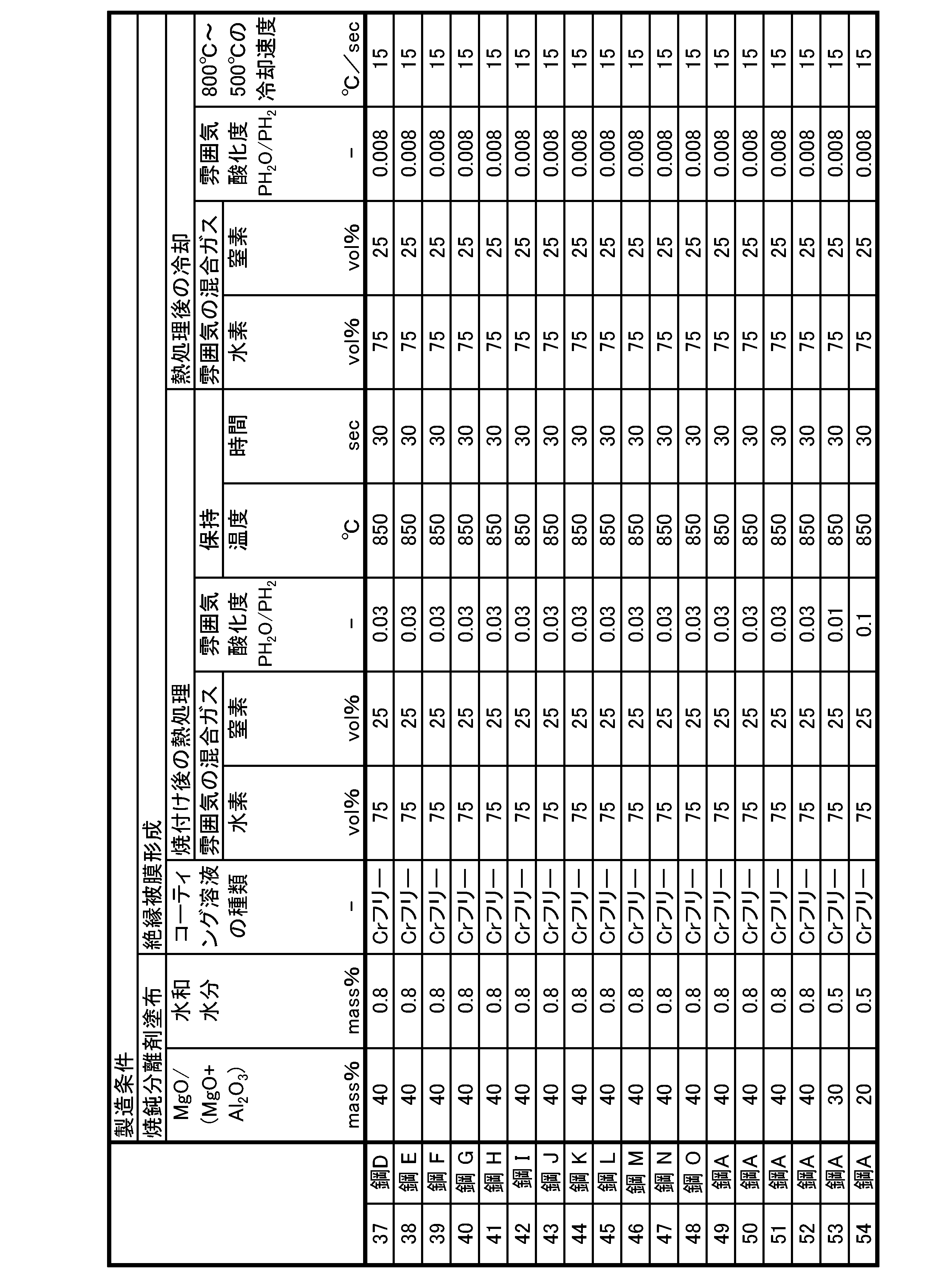

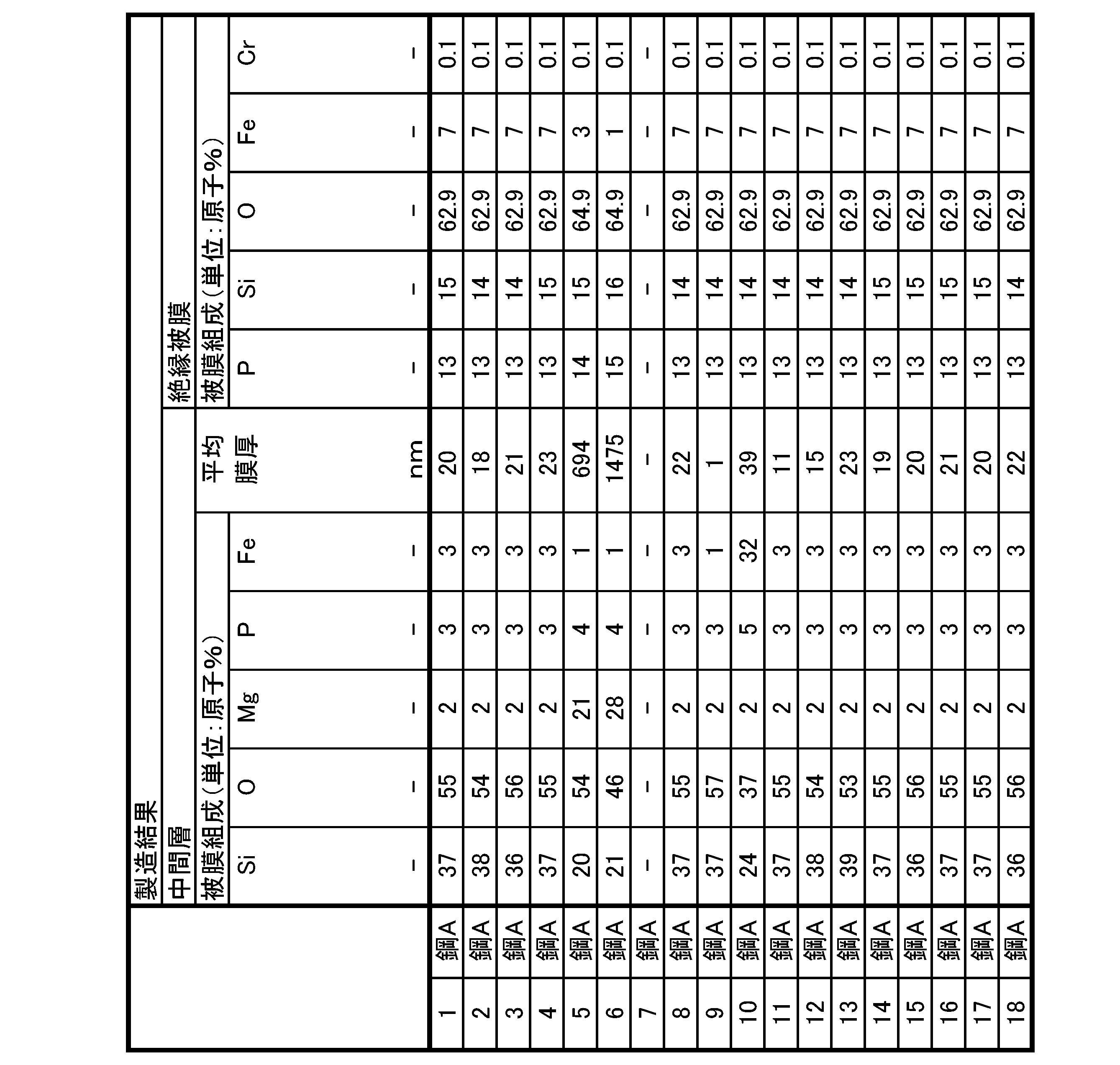


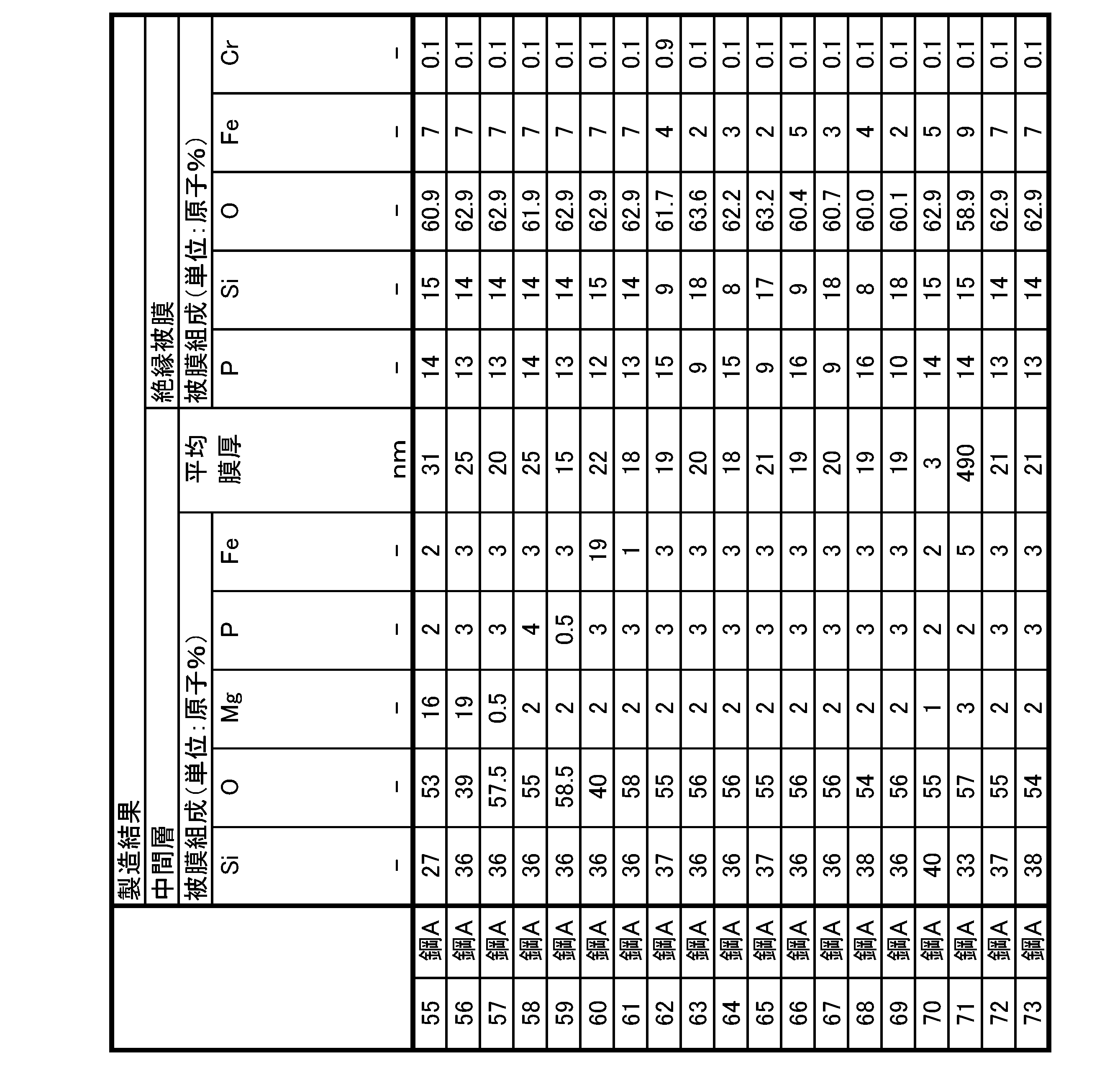


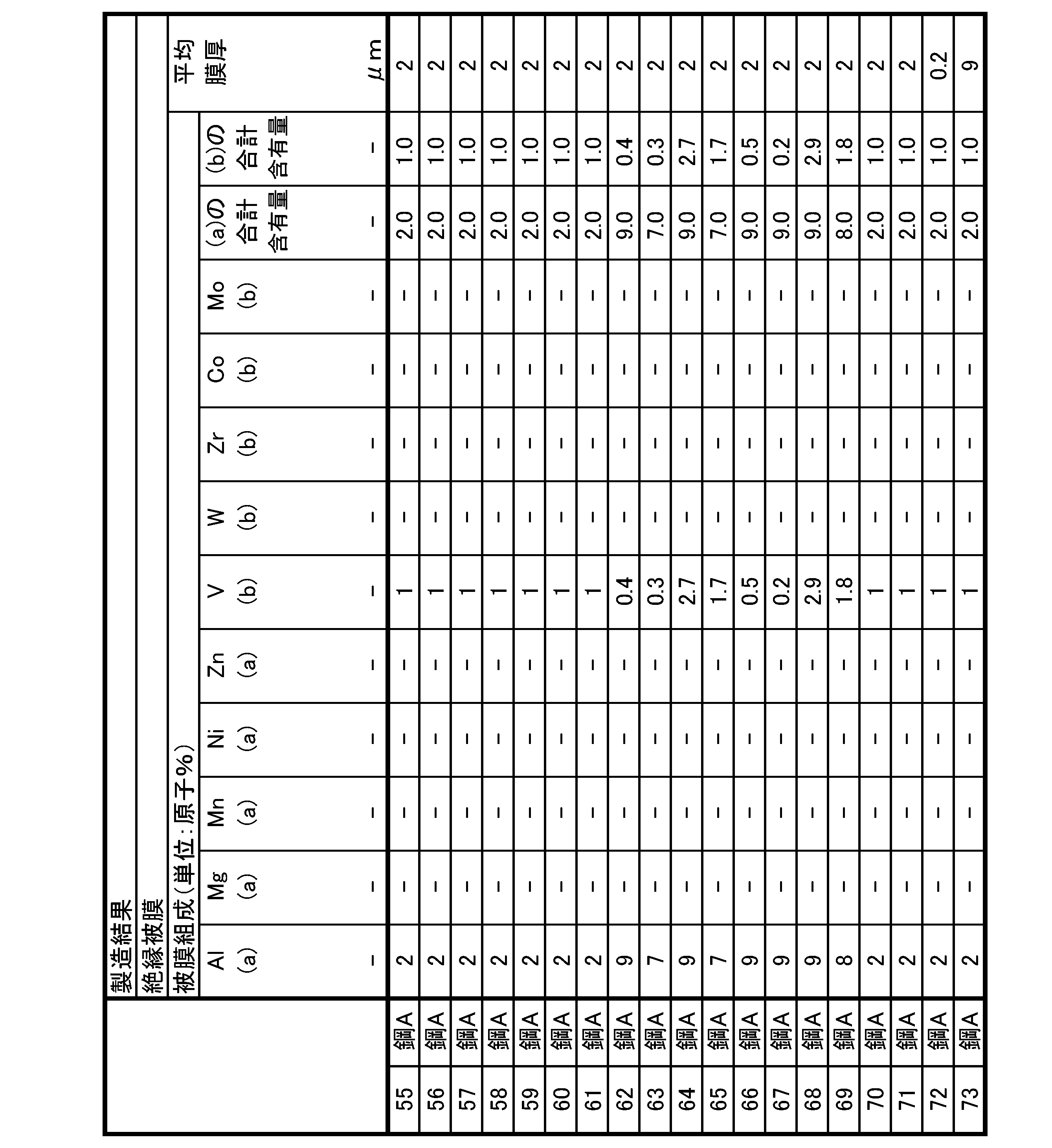


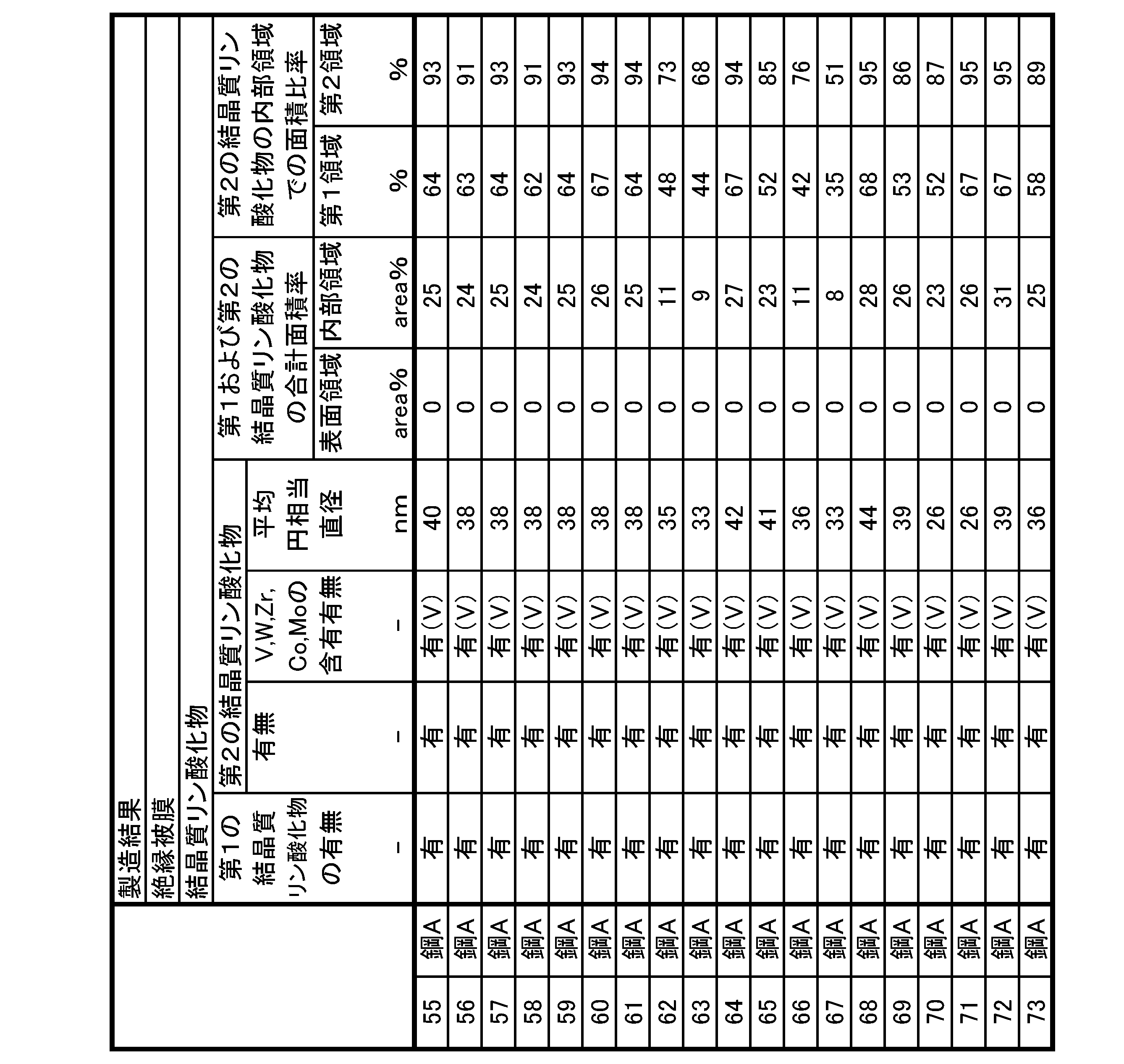


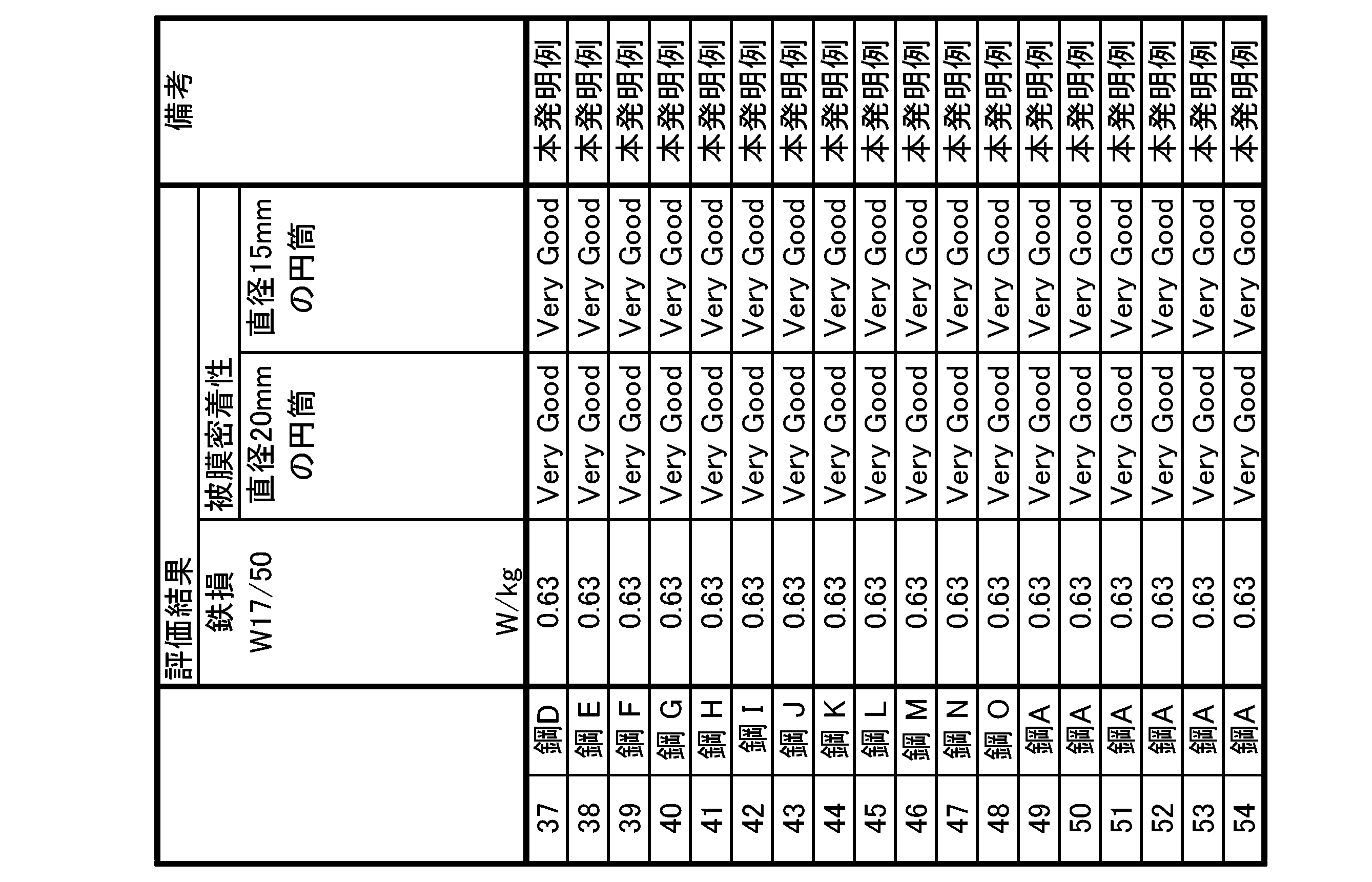

2 中間層(酸化膜)
3 絶縁被膜(リン酸系被膜)
31 内部領域
31a 第1の内部領域
31b 第2の内部領域
32 表面領域
Claims (6)
- 珪素鋼板である母材鋼板と、
前記珪素鋼板上に接して配された中間層と、
前記中間層上に接して配された絶縁被膜と、
を有する方向性電磁鋼板において、
前記中間層が、
Si含有量:20原子%以上70原子%以下、
O含有量 :30原子%以上80原子%以下、
Mg含有量:20原子%未満、
P含有量 :5原子%未満、
Fe含有量:20原子%未満、
を満たす酸化膜であり、且つ
前記酸化膜の平均膜厚が、2nm以上500nm以下であり、
前記絶縁被膜が、
P含有量 :5原子%以上30原子%以下、
Si含有量:5原子%以上30原子%以下、
O含有量 :30原子%以上80原子%以下、
Fe含有量:1原子%以上25原子%未満、
Cr含有量:1.0原子%未満、
Al含有量:0原子%以上10原子%以下、
Mg含有量:0原子%以上10原子%以下、
Mn含有量:0原子%以上10原子%以下、
Ni含有量:0原子%以上10原子%以下、
Zn含有量:0原子%以上10原子%以下、
Al+Mg+Mn+Ni+Znの合計含有量:0.1原子%以上10原子%以下、
V含有量 :0原子%以上10原子%以下、
W含有量 :0原子%以上10原子%以下、
Zr含有量:0原子%以上10原子%以下、
Co含有量:0原子%以上10原子%以下、
Mo含有量:0原子%以上10原子%以下、
V+W+Zr+Co+Moの合計含有量:0.1原子%以上10原子%以下、
を満たすリン酸系被膜であり、且つ
前記リン酸系被膜の平均膜厚が、0.1μm以上10μm以下であり、
前記リン酸系被膜中に、結晶構造がFe2P2O7に対応する第1の結晶質リン酸化物と、結晶構造がFe7(P2O7)4に対応する第2の結晶質リン酸化物とが含まれ、
前記第2の結晶質リン酸化物に、V、W、Zr、Co、およびMoからなるグループから選択される少なくとも1種が含まれる、
ことを特徴とする方向性電磁鋼板。 - 前記リン酸系被膜を、切断方向が板厚方向と平行な切断面上で前記板厚方向に沿って、前記酸化膜に接している内部領域と、前記酸化膜に接していない表面領域とに2等分割したとき、
前記表面領域に含まれる前記第1の結晶質リン酸化物および前記第2の結晶質リン酸化物の合計面積率より、前記内部領域に含まれる前記第1の結晶質リン酸化物および前記第2の結晶質リン酸化物の合計面積率が大きい、
ことを特徴とする請求項1に記載の方向性電磁鋼板。 - 前記表面領域に含まれる前記第1の結晶質リン酸化物および前記第2の結晶質リン酸化物の前記合計面積率が0%以上30%以下であり、前記内部領域に含まれる前記第1の結晶質リン酸化物および前記第2の結晶質リン酸化物の前記合計面積率が3%以上50%以下である、
ことを特徴とする請求項2に記載の方向性電磁鋼板。 - 前記内部領域を、前記切断面上で前記板厚方向に沿って、前記酸化膜に接している第1の内部領域と、前記酸化膜に接していない第2の内部領域とに2等分割し、
前記第1の内部領域に含まれる前記第2の結晶質リン酸化物の面積率を、前記第1の内部領域に含まれる前記第1の結晶質リン酸化物および前記第2の結晶質リン酸化物の合計面積率で割った値の百分率を、第1の面積比率とし、
前記第2の内部領域に含まれる前記第2の結晶質リン酸化物の面積率を、前記第2の内部領域に含まれる前記第1の結晶質リン酸化物および前記第2の結晶質リン酸化物の合計面積率で割った値の百分率を、第2の面積比率としたとき、
前記第1の面積比率より、前記第2の面積比率が大きい、
ことを特徴とする請求項2または請求項3に記載の方向性電磁鋼板。 - 前記第1の面積比率が0%以上70%以下であり、前記第2の面積比率が50%以上100%以下である、
ことを特徴とする請求項4に記載の方向性電磁鋼板。 - 前記第2の結晶質リン酸化物の円相当直径が、平均で5nm以上300nm以下である、ことを特徴とする請求項1~5の何れか1項に記載の方向性電磁鋼板。
Priority Applications (5)
| Application Number | Priority Date | Filing Date | Title |
|---|---|---|---|
| JP2023524262A JPWO2022250168A1 (ja) | 2021-05-28 | 2022-05-30 | |
| EP22811436.9A EP4350033A1 (en) | 2021-05-28 | 2022-05-30 | Grain-oriented electromagnetic steel sheet |
| KR1020237040411A KR20240000581A (ko) | 2021-05-28 | 2022-05-30 | 방향성 전자 강판 |
| CN202280037619.2A CN117396633A (zh) | 2021-05-28 | 2022-05-30 | 方向性电磁钢板 |
| BR112023024536A BR112023024536A2 (pt) | 2021-05-28 | 2022-05-30 | Chapa de aço elétrico de grão orientado |
Applications Claiming Priority (2)
| Application Number | Priority Date | Filing Date | Title |
|---|---|---|---|
| JP2021-090213 | 2021-05-28 | ||
| JP2021090213 | 2021-05-28 |
Publications (1)
| Publication Number | Publication Date |
|---|---|
| WO2022250168A1 true WO2022250168A1 (ja) | 2022-12-01 |
Family
ID=84228983
Family Applications (1)
| Application Number | Title | Priority Date | Filing Date |
|---|---|---|---|
| PCT/JP2022/021936 WO2022250168A1 (ja) | 2021-05-28 | 2022-05-30 | 方向性電磁鋼板 |
Country Status (6)
| Country | Link |
|---|---|
| EP (1) | EP4350033A1 (ja) |
| JP (1) | JPWO2022250168A1 (ja) |
| KR (1) | KR20240000581A (ja) |
| CN (1) | CN117396633A (ja) |
| BR (1) | BR112023024536A2 (ja) |
| WO (1) | WO2022250168A1 (ja) |
Citations (11)
| Publication number | Priority date | Publication date | Assignee | Title |
|---|---|---|---|---|
| JPS4996920A (ja) | 1973-01-22 | 1974-09-13 | ||
| WO2002088403A1 (fr) | 2001-04-23 | 2002-11-07 | Nippon Steel Corporation | Procede de production de tole d'acier au silicium unidirectionnel exempte de pellicule de revetement minerale inorganique |
| JP2009041074A (ja) * | 2007-08-09 | 2009-02-26 | Jfe Steel Kk | 方向性電磁鋼板用クロムフリー絶縁被膜処理液および絶縁被膜付方向性電磁鋼板の製造方法 |
| JP2017137540A (ja) * | 2016-02-05 | 2017-08-10 | 新日鐵住金株式会社 | 方向性電磁鋼板の絶縁被膜用処理剤、方向性電磁鋼板、及び、方向性電磁鋼板の絶縁被膜処理方法 |
| WO2018051902A1 (ja) * | 2016-09-13 | 2018-03-22 | Jfeスチール株式会社 | クロムフリー絶縁張力被膜付き方向性電磁鋼板およびその製造方法 |
| WO2019013350A1 (ja) | 2017-07-13 | 2019-01-17 | 新日鐵住金株式会社 | 方向性電磁鋼板 |
| WO2019013353A1 (ja) | 2017-07-13 | 2019-01-17 | 新日鐵住金株式会社 | 方向性電磁鋼板 |
| WO2020149337A1 (ja) * | 2019-01-16 | 2020-07-23 | 日本製鉄株式会社 | 方向性電磁鋼板の製造方法 |
| WO2020149332A1 (ja) * | 2019-01-16 | 2020-07-23 | 日本製鉄株式会社 | 方向性電磁鋼板の製造方法 |
| WO2020149319A1 (ja) * | 2019-01-16 | 2020-07-23 | 日本製鉄株式会社 | 方向性電磁鋼板およびその製造方法 |
| JP2021090213A (ja) | 2021-02-10 | 2021-06-10 | アンリツ株式会社 | 平衡不平衡変換器及びそれを備えた半導体集積回路 |
-
2022
- 2022-05-30 JP JP2023524262A patent/JPWO2022250168A1/ja active Pending
- 2022-05-30 CN CN202280037619.2A patent/CN117396633A/zh active Pending
- 2022-05-30 WO PCT/JP2022/021936 patent/WO2022250168A1/ja active Application Filing
- 2022-05-30 BR BR112023024536A patent/BR112023024536A2/pt unknown
- 2022-05-30 EP EP22811436.9A patent/EP4350033A1/en active Pending
- 2022-05-30 KR KR1020237040411A patent/KR20240000581A/ko unknown
Patent Citations (11)
| Publication number | Priority date | Publication date | Assignee | Title |
|---|---|---|---|---|
| JPS4996920A (ja) | 1973-01-22 | 1974-09-13 | ||
| WO2002088403A1 (fr) | 2001-04-23 | 2002-11-07 | Nippon Steel Corporation | Procede de production de tole d'acier au silicium unidirectionnel exempte de pellicule de revetement minerale inorganique |
| JP2009041074A (ja) * | 2007-08-09 | 2009-02-26 | Jfe Steel Kk | 方向性電磁鋼板用クロムフリー絶縁被膜処理液および絶縁被膜付方向性電磁鋼板の製造方法 |
| JP2017137540A (ja) * | 2016-02-05 | 2017-08-10 | 新日鐵住金株式会社 | 方向性電磁鋼板の絶縁被膜用処理剤、方向性電磁鋼板、及び、方向性電磁鋼板の絶縁被膜処理方法 |
| WO2018051902A1 (ja) * | 2016-09-13 | 2018-03-22 | Jfeスチール株式会社 | クロムフリー絶縁張力被膜付き方向性電磁鋼板およびその製造方法 |
| WO2019013350A1 (ja) | 2017-07-13 | 2019-01-17 | 新日鐵住金株式会社 | 方向性電磁鋼板 |
| WO2019013353A1 (ja) | 2017-07-13 | 2019-01-17 | 新日鐵住金株式会社 | 方向性電磁鋼板 |
| WO2020149337A1 (ja) * | 2019-01-16 | 2020-07-23 | 日本製鉄株式会社 | 方向性電磁鋼板の製造方法 |
| WO2020149332A1 (ja) * | 2019-01-16 | 2020-07-23 | 日本製鉄株式会社 | 方向性電磁鋼板の製造方法 |
| WO2020149319A1 (ja) * | 2019-01-16 | 2020-07-23 | 日本製鉄株式会社 | 方向性電磁鋼板およびその製造方法 |
| JP2021090213A (ja) | 2021-02-10 | 2021-06-10 | アンリツ株式会社 | 平衡不平衡変換器及びそれを備えた半導体集積回路 |
Also Published As
| Publication number | Publication date |
|---|---|
| EP4350033A1 (en) | 2024-04-10 |
| BR112023024536A2 (pt) | 2024-02-15 |
| KR20240000581A (ko) | 2024-01-02 |
| JPWO2022250168A1 (ja) | 2022-12-01 |
| CN117396633A (zh) | 2024-01-12 |
Similar Documents
| Publication | Publication Date | Title |
|---|---|---|
| US11186891B2 (en) | Grain-oriented electrical steel sheet and method for producing same | |
| JP7299511B2 (ja) | 方向性電磁鋼板の製造方法 | |
| JP6915690B2 (ja) | 方向性電磁鋼板 | |
| JP6828820B2 (ja) | 方向性電磁鋼板、及び方向性電磁鋼板の製造方法 | |
| JP7235058B2 (ja) | 方向性電磁鋼板の製造方法 | |
| JP7188458B2 (ja) | 方向性電磁鋼板およびその製造方法 | |
| WO2020149340A1 (ja) | 方向性電磁鋼板およびその製造方法 | |
| JP7269505B2 (ja) | 方向性電磁鋼板の製造方法 | |
| WO2022250168A1 (ja) | 方向性電磁鋼板 | |
| JP7299512B2 (ja) | 方向性電磁鋼板の製造方法 | |
| JP7315857B2 (ja) | 方向性電磁鋼板の製造方法 | |
| WO2020149330A1 (ja) | 方向性電磁鋼板の製造方法 | |
| WO2022250163A1 (ja) | 方向性電磁鋼板 | |
| JP7200687B2 (ja) | 方向性電磁鋼板及びその製造方法 | |
| US20240186042A1 (en) | Grain-oriented electrical steel sheet | |
| WO2023204269A1 (ja) | 方向性電磁鋼板およびその製造方法 | |
| JP7188105B2 (ja) | 方向性電磁鋼板 | |
| WO2023204266A1 (ja) | 方向性電磁鋼板およびその製造方法 | |
| RU2776382C1 (ru) | Лист анизотропной электротехнической стали и способ его производства | |
| JP7230930B2 (ja) | 方向性電磁鋼板の製造方法 | |
| WO2023204267A1 (ja) | 方向性電磁鋼板およびその製造方法 | |
| JP7269504B2 (ja) | 方向性電磁鋼板の製造方法 | |
| WO2022215710A1 (ja) | 方向性電磁鋼板及び絶縁被膜の形成方法 | |
| WO2022215709A1 (ja) | 方向性電磁鋼板及び絶縁被膜の形成方法 | |
| JP2020111811A (ja) | 方向性電磁鋼板 |
Legal Events
| Date | Code | Title | Description |
|---|---|---|---|
| 121 | Ep: the epo has been informed by wipo that ep was designated in this application |
Ref document number: 22811436 Country of ref document: EP Kind code of ref document: A1 |
|
| WWE | Wipo information: entry into national phase |
Ref document number: 2023524262 Country of ref document: JP |
|
| ENP | Entry into the national phase |
Ref document number: 20237040411 Country of ref document: KR Kind code of ref document: A |
|
| WWE | Wipo information: entry into national phase |
Ref document number: 1020237040411 Country of ref document: KR |
|
| WWE | Wipo information: entry into national phase |
Ref document number: 202280037619.2 Country of ref document: CN Ref document number: 18564043 Country of ref document: US |
|
| REG | Reference to national code |
Ref country code: BR Ref legal event code: B01A Ref document number: 112023024536 Country of ref document: BR |
|
| WWE | Wipo information: entry into national phase |
Ref document number: 2023130835 Country of ref document: RU |
|
| NENP | Non-entry into the national phase |
Ref country code: DE |
|
| WWE | Wipo information: entry into national phase |
Ref document number: 2022811436 Country of ref document: EP |
|
| ENP | Entry into the national phase |
Ref document number: 2022811436 Country of ref document: EP Effective date: 20240102 |
|
| ENP | Entry into the national phase |
Ref document number: 112023024536 Country of ref document: BR Kind code of ref document: A2 Effective date: 20231123 |