WO2022250048A1 - 画像処理方法、画像処理装置、及びプログラム - Google Patents
画像処理方法、画像処理装置、及びプログラム Download PDFInfo
- Publication number
- WO2022250048A1 WO2022250048A1 PCT/JP2022/021237 JP2022021237W WO2022250048A1 WO 2022250048 A1 WO2022250048 A1 WO 2022250048A1 JP 2022021237 W JP2022021237 W JP 2022021237W WO 2022250048 A1 WO2022250048 A1 WO 2022250048A1
- Authority
- WO
- WIPO (PCT)
- Prior art keywords
- light
- oct
- scan data
- image
- data
- Prior art date
- Legal status (The legal status is an assumption and is not a legal conclusion. Google has not performed a legal analysis and makes no representation as to the accuracy of the status listed.)
- Ceased
Links
Images




Classifications
-
- A—HUMAN NECESSITIES
- A61—MEDICAL OR VETERINARY SCIENCE; HYGIENE
- A61B—DIAGNOSIS; SURGERY; IDENTIFICATION
- A61B3/00—Apparatus for testing the eyes; Instruments for examining the eyes
- A61B3/10—Objective types, i.e. instruments for examining the eyes independent of the patients' perceptions or reactions
Definitions
- the technology of the present disclosure relates to an image processing method, an image processing device, and a program.
- US Publication No. 2020/0214557 discloses a technique for acquiring a tomographic image of an eye to be examined. Acquiring a tomographic image at a wide angle is desired.
- An image processing method is image processing performed by a processor, and is based on interference light between return light and reference light obtained by scanning signal light.
- the method includes acquiring OCT data and correcting differences in contrast of a plurality of A-scan data included in the OCT data to generate corrected OCT data.
- An image processing apparatus is an image processing apparatus including a processor, wherein the processor generates a acquiring OCT data of the fundus of the eye to be inspected using a device; and correcting differences in contrast of a plurality of A-scan data included in the OCT data to generate corrected OCT data.
- a program is provided in a computer, acquiring OCT data of the fundus of an eye to be inspected based on interference light between a return light obtained by scanning a signal light and a reference light; and C. correcting differences in contrast of a plurality of A-scan data included in the OCT data to generate corrected OCT data.
- FIG. 1 is a block diagram of an ophthalmic system 100;
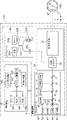
- FIG. 1 is a block diagram showing the overall configuration of an ophthalmologic apparatus 110.
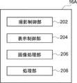
- FIG. 4 is an explanatory diagram of functions realized by an image processing program executed by the CPU 16A of the ophthalmologic apparatus 110;
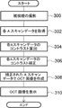
- FIG. 4 is a flowchart showing image processing performed by a CPU 16A;
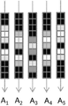
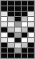
- FIG. 4 is a diagram showing the relationship between scan angle and polarization and A-scan; It is a figure which shows each A scan data.
- 6B is a diagram showing an OCT image based on each A-scan data of FIG. 6A;
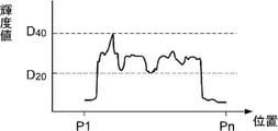
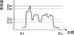
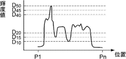
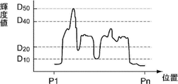
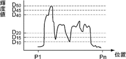
- FIG. 10 is a diagram of calculated contrast of A1 scan data; It is the figure which calculated the contrast of A2 scan data.
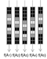
- FIG. 8B is a diagram showing an OCT image based on each A-scan data after the correction in FIG. 8A; 7B is a diagram obtained by correcting the contrast of the A1 scan data of FIG. 7A; FIG. 7C is a diagram obtained by correcting the contrast of the A2 scan data of FIG. 7B; FIG. 5 shows a screen shot 500 displayed on viewer 150.
- FIG. 8B is a diagram showing an OCT image based on each A-scan data after the correction in FIG. 8A; 7B is a diagram obtained by correcting the contrast of the A1 scan data of FIG. 7A; FIG. 7C is a diagram obtained by correcting the contrast of the A2 scan data of FIG. 7B; FIG. 5 shows a screen shot 500 displayed on viewer 150.
- FIG. 1 shows a schematic configuration of an ophthalmic system 100.
- the ophthalmologic system 100 includes an ophthalmologic apparatus 110 , a server apparatus (hereinafter referred to as “server”) 140 , and a display apparatus (hereinafter referred to as “viewer”) 150 .
- the ophthalmologic device 110 acquires a fundus image.
- the server 140 associates a plurality of fundus images obtained by photographing the fundus of a plurality of patients with the ophthalmologic apparatus 110 and the axial length measured by an axial length measuring device (not shown) with the patient ID. memorize.
- the viewer 150 displays the fundus image acquired by the server 140 and the analysis results.
- the ophthalmologic apparatus 110 is an example of the "image processing apparatus" of the technology of the present disclosure.
- Network 130 is any network such as LAN, WAN, the Internet, or a wide area Ethernet network.
- LAN local area network
- WAN wide area network
- Ethernet wide area Ethernet network
- the viewer 150 is a client in a client-server system, and a plurality of viewers 150 are connected via a network. Also, a plurality of servers 140 may be connected via a network in order to ensure system redundancy.
- the ophthalmologic apparatus 110 has an image processing function and an image viewing function of the viewer 150, the ophthalmologic apparatus 110 can acquire, process, and view fundus images in a stand-alone state.
- the server 140 has the image viewing function of the viewer 150, the configuration of the ophthalmologic apparatus 110 and the server 140 enables fundus image acquisition, image processing, and image viewing.
- ophthalmologic equipment inspection equipment for visual field measurement, intraocular pressure measurement, etc.
- diagnosis support device that performs image analysis using AI (Artificial Intelligence) are connected via the network 130 to the ophthalmic equipment 110, the server 140, and the viewer. 150 may be connected.
- AI Artificial Intelligence
- SLO scanning laser ophthalmoscope
- OCT optical coherence tomography
- the horizontal direction is the "X direction”
- the vertical direction to the horizontal plane is the "Y direction”.
- the ophthalmologic device 110 includes an imaging device 14 and a control device 16 .
- the imaging device 14 includes an SLO unit 18 and an OCT unit 20 and acquires a fundus image of the eye 12 to be examined.
- the two-dimensional fundus image acquired by the SLO unit 18 is hereinafter referred to as an SLO image.
- a tomographic image of the retina, a front image (en-face image), and the like created based on the OCT data acquired by the OCT unit 20 are referred to as OCT images.
- the control device 16 comprises a computer having a CPU (Central Processing Unit) 16A, a RAM (Random Access Memory) 16B, a ROM (Read-Only Memory) 16C, and an input/output (I/O) port 16D. ing.
- the ROM 16C stores an image processing program shown in FIG. 4, which will be described later.
- the CPU 16A is an example of the "processor” of the technology of the present disclosure.
- the ROM 16C is an example of the “storage unit” of the technology of the present disclosure.
- Controller 16 is an example of a "computer program product.”
- the control device 16 has an input/display device 16E connected to the CPU 16A via an I/O port 16D.
- the input/display device 16E has a graphic user interface that displays an image of the subject's eye 12 and receives various instructions from the user. Graphic user interfaces include touch panel displays.
- the control device 16 also includes an image processor 17 connected to the I/O port 16D.
- the image processor 17 generates an image of the subject's eye 12 based on the data obtained by the imaging device 14 .
- the control device 16 is connected to the network 130 via the communication interface 16F.
- the control device 16 of the ophthalmic device 110 includes the input/display device 16E, but the technology of the present disclosure is not limited to this.
- the controller 16 of the ophthalmic device 110 may not have the input/display device 16E, but may have a separate input/display device physically separate from the ophthalmic device 110.
- the display device includes an image processor unit that operates under the control of the display control section 204 of the CPU 16A of the control device 16.
- FIG. The image processor unit may display an SLO image or the like based on the image signal output by the display control unit 204 .
- the imaging device 14 operates under the control of the CPU 16A of the control device 16.
- the imaging device 14 includes an SLO unit 18 , an imaging optical system 19 and an OCT unit 20 .
- the imaging optical system 19 includes an optical scanner 22 and a wide-angle optical system 30 .
- the optical scanner 22 two-dimensionally scans the light emitted from the SLO unit 18 in the X and Y directions.
- the optical scanner 22 may be any optical element capable of deflecting a light beam, such as a polygon mirror or a galvanomirror. Moreover, those combinations may be sufficient.
- the optical scanner 22 synthesizes the light from the SLO unit 18 and the light from the OCT unit 20.
- the wide-angle optical system 30 may be a reflective optical system using a concave mirror such as an elliptical mirror, a refractive optical system using a wide-angle lens, or a catadioptric system combining concave mirrors and lenses.
- a wide-angle optical system using an elliptical mirror, a wide-angle lens, etc. it is possible to photograph not only the central part of the fundus but also the peripheral part of the retina.
- the wide-angle optical system 30 realizes observation in a wide field of view (FOV: Field of View) 12A at the fundus.
- the FOV 12A indicates a range that can be photographed by the photographing device 14.
- FIG. FOV12A can be expressed as a viewing angle.
- a viewing angle may be defined by an internal illumination angle and an external illumination angle in this embodiment.
- the external irradiation angle is an irradiation angle defined by using the pupil 27 as a reference for the irradiation angle of the light beam irradiated from the ophthalmologic apparatus 110 to the eye 12 to be examined.
- the internal illumination angle is an illumination angle defined by using the eyeball center O as a reference for the illumination angle of the luminous flux that illuminates the fundus F.
- the external illumination angle and the internal illumination angle are in correspondence. For example, an external illumination angle of 120 degrees corresponds to an internal illumination angle of approximately 160 degrees. In this embodiment, the internal illumination angle is 200 degrees.
- UWF-SLO fundus image an SLO fundus image obtained by photographing at an angle of view of 160 degrees or more with an internal irradiation angle is referred to as a UWF-SLO fundus image.
- UWF is an abbreviation for UltraWide Field.
- the wide-angle optical system 30, which has an ultra-wide field of view (FOV) of the fundus, can image the area beyond the posterior pole of the fundus of the eye 12 to be examined and beyond the equator. You can take pictures of existing structures.
- FOV ultra-wide field of view
- the ophthalmologic apparatus 110 can photograph the region 12A with an internal illumination angle of 200° with the eyeball center O of the subject's eye 12 as a reference position.
- the internal illumination angle of 200° is 110° in terms of the external illumination angle with the pupil of the eyeball of the subject's eye 12 as a reference.
- the wide-angle optical system 30 irradiates the laser light from the pupil with an external irradiation angle of 110°, and photographs the fundus region with an internal irradiation angle of 200°.
- the SLO system is implemented by the control device 16, SLO unit 18, and imaging optical system 19 shown in FIG. Since the SLO system includes the wide-angle optical system 30, it enables fundus imaging with a wide FOV 12A.
- the SLO unit 18 includes a B light (blue light) light source 40, a G light (green light) light source 42, an R light (red light) light source 44, and an IR light (infrared (for example, near infrared light)) light source. It comprises a light source 46 and optical systems 48, 50, 52, 54 and 56 that reflect or transmit the light from the light sources 40, 42, 44 and 46 and guide them to one optical path.
- Optical systems 48, 56 are mirrors and optical systems 50, 52, 54 are beam splitters.
- the B light is reflected by the optical system 48, transmitted through the optical system 50, and reflected by the optical system 54, the G light is reflected by the optical systems 50 and 54, and the R light is transmitted by the optical systems 52 and 54.
- the IR light is reflected by optical systems 52 and 56 and directed to one optical path, respectively.
- the SLO unit 18 is configured to be switchable between a light source that emits laser light with different wavelengths, such as a mode that emits R light and G light, and a mode that emits infrared light, or a combination of light sources that emit light.
- a light source that emits laser light with different wavelengths
- the example shown in FIG. 2 includes four light sources, that is, the B light source 40, the G light source 42, the R light source 44, and the IR light source 46
- the technology of the present disclosure is not limited to this.
- the SLO unit 18 may further include a white light source and emit light in various modes such as a mode emitting G light, R light, and B light, and a mode emitting only white light. good.
- the light that has entered the imaging optical system 19 from the SLO unit 18 is scanned in the X and Y directions by the optical scanner 22 .
- the scanning light passes through the wide-angle optical system 30 and the pupil 27 and illuminates the fundus. Reflected light reflected by the fundus enters the SLO unit 18 via the wide-angle optical system 30 and the optical scanner 22 .
- the SLO unit 18 has a beam splitter 64 that reflects the B light from the posterior segment (fundus) of the subject's eye 12 and transmits other than the B light, and G light from the light transmitted through the beam splitter 64 .
- a beam splitter 58 that reflects and transmits light other than G light is provided.
- the SLO unit 18 has a beam splitter 60 that reflects the R light and transmits other than the R light out of the light transmitted through the beam splitter 58 .
- the SLO unit 18 has a beam splitter 62 that reflects IR light out of the light transmitted through the beam splitter 60 .
- the SLO unit 18 includes a B light detection element 70 for detecting B light reflected by the beam splitter 64, a G light detection element 72 for detecting G light reflected by the beam splitter 58, and an R light reflected by the beam splitter 60.
- An R photodetector element 74 and an IR photodetector element 76 for detecting IR light reflected by the beam splitter 62 are provided.
- the light (reflected light reflected by the fundus) that is incident on the SLO unit 18 via the wide-angle optical system 30 and the optical scanner 22 is reflected by the beam splitter 64 and received by the B light detection element 70 in the case of B light.
- the beam splitter 58 In the case of G light, it is reflected by the beam splitter 58 and received by the G light detection element 72 .
- the incident light, in the case of R light passes through the beam splitter 58 , is reflected by the beam splitter 60 , and is received by the R light detection element 74 .
- the incident light, in the case of IR light passes through the beam splitters 58 and 60 , is reflected by the beam splitter 62 , and is received by the IR photodetector 76 .
- the image processor 17 operating under the control of the CPU 16A uses the signals detected by the B photodetector 70, the G photodetector 72, the R photodetector 74, and the IR photodetector 76 to produce a UWF-SLO image. Generate.
- a UWF-SLO image generated using the signal detected by the B photodetector 70 is called a B-UWF-SLO image (B-color fundus image).
- a UWF-SLO image generated using the signals detected by the G photodetector 72 is called a G-UWF-SLO image (G color fundus image).
- a UWF-SLO image generated using the signal detected by the R photodetector 74 is called an R-UWF-SLO image (R color fundus image).
- a UWF-SLO image generated using the signal detected by the IR photodetector 76 is called an IR-UWF-SLO image (IR fundus image).
- UWF-SLO images include these R-color fundus images, G-color fundus images, B-color fundus images, and IR fundus images. Also included is a fluorescence UWF-SLO image of fluorescence.
- control device 16 controls the light sources 40, 42, 44 to emit light simultaneously.
- a G-color fundus image, an R-color fundus image, and a B-color fundus image whose respective positions correspond to each other are obtained.
- An RGB color fundus image is obtained from the G color fundus image, the R color fundus image, and the B color fundus image.
- the control device 16 controls the light sources 42 and 44 to emit light at the same time, and the fundus of the subject's eye 12 is photographed simultaneously with the G light and the R light, thereby obtaining a G-color fundus image and an R-color fundus image corresponding to each other at each position.
- a fundus image is obtained.
- An RG color fundus image is obtained from the G color fundus image and the R color fundus image.
- a full-color fundus image may be generated using the G-color fundus image, the R-color fundus image, and the B-color fundus image.
- the field of view (FOV) of the fundus can be set to a super-wide angle, and the area extending from the posterior pole of the fundus to the equator of the subject's eye 12 can be photographed.
- the OCT system is implemented by the control device 16, OCT unit 20, and imaging optical system 19 shown in FIG. Since the OCT system includes the wide-angle optical system 30, OCT imaging of the peripheral part of the fundus can be performed in the same manner as the SLO fundus image imaging described above. In other words, the wide-angle optical system 30 with a super-wide field of view (FOV) of the eye fundus captures the fundus of the subject's eye 12 at a wide angle. It is possible to perform OCT imaging of a region exceeding It is possible to acquire OCT data of structures such as vortex veins that exist in the peripheral part of the eye fundus, and obtain 3D structures of vortex veins by performing image processing on tomographic images of vortex veins and OCT data.
- FOV super-wide field of view
- the OCT unit 20 includes a light source 20A, a sensor (detection element) 20B, a first optical coupler 20C, a reference optical system 20D, a collimating lens 20E, and a second optical coupler 20F.
- the light emitted from the light source 20A is split by the first optical coupler 20C.
- One of the split lights is collimated by the collimating lens 20E and then enters the imaging optical system 19 as signal light.
- the signal light passes through the wide-angle optical system 30 and the pupil 27 and illuminates the fundus.
- the signal light reflected by the fundus enters the OCT unit 20 via the wide-angle optical system 30, and enters the second optical coupler 20F via the collimating lens 20E and the first optical coupler 20C.
- the other light emitted from the light source 20A and branched by the first optical coupler 20C enters the reference optical system 20D as reference light, passes through the reference optical system 20D, and enters the second optical coupler 20F. do.
- the image processor 17 operating under the control of the image processor 206 performs processing such as Fourier transform on the detection signal detected by the sensor 20B to generate OCT data. It is also possible for the image processor 17 to generate an OCT image such as a tomographic image or an en-face image based on the OCT data.
- the OCT unit 20 can scan a predetermined range (for example, a rectangular range of 6 mm x 6 mm) in one OCT imaging.
- the predetermined range is not limited to 6 mm x 6 mm, but may be a square range of 12 mm x 12 mm or 23 mm x 23 mm, or a rectangular range such as 14 mm x 9 mm, 6 mm x 3.5 mm, or any rectangular range. can. It may also be in a range of circular diameters such as 6 mm, 12 mm, and 23 mm in diameter.
- the ophthalmologic apparatus 110 can scan the region 12A with an internal irradiation angle of 200°. That is, by controlling the optical scanner 22, OCT imaging of a predetermined range including vortex veins is performed. The ophthalmologic apparatus 110 can generate OCT data through the OCT imaging.
- the ophthalmologic apparatus 110 can generate OCT images such as tomographic images (B-scan images) of the fundus including vortex veins, OCT volume data including vortex veins, and en-face images (OCT images) which are cross sections of the OCT volume data.
- OCT images such as tomographic images (B-scan images) of the fundus including vortex veins, OCT volume data including vortex veins, and en-face images (OCT images) which are cross sections of the OCT volume data.
- a frontal image generated based on the volume data can be generated.
- the OCT image includes an OCT image of the central part of the fundus (the posterior pole part of the eyeball where the macula, the optic papilla, etc. are present).
- the OCT data (or image data of an OCT image) is sent from the ophthalmologic apparatus 110 to the server 140 via the communication interface 16F and stored in a storage device (not shown).
- the light source 20A exemplifies a wavelength sweep type SS-OCT (Swept-Source OCT). It may be an OCT system of any type.
- SS-OCT Tin-Source OCT
- the image processing program has a shooting control function, a display control function, an image processing function, and a processing function.
- the CPU 16A functions as a shooting control unit 202, a display control unit 204, an image processing unit 206, and a processing unit 208, as shown in FIG.
- the image processing unit 206 is an example of the “acquisition unit” and the “generation unit” of the technology of the present disclosure.
- the CPU 16A of the control device 16 of the ophthalmologic apparatus 110 executes the image processing program to implement the image processing shown in the flowchart of FIG.
- the processing shown in the flowchart of FIG. 4 is an example of the "image processing method" of the technology of the present disclosure.
- Patient information (patient ID, name, gender, age, and whether the eye to be examined is the right or left eye) is input via the display screen of the input/display device 16E, and the start button provided on the display screen is pressed. Once actuated, the image processing process shown in FIG. 4 is started.
- the display control unit 204 and the imaging control unit 202 control the OCT unit 20 and the imaging optical system 19 to capture a desired imaging range of the fundus of the subject's eye 12 specified by the user.
- the display control unit 204 displays a display screen for OCT imaging on the input/display device 16E.
- a UWF fundus image and an OCT imaging start button are displayed on the display screen. The user designates a desired imaging range on the UWF fundus image and operates an OCT imaging start button.
- the photographing control unit 202 controls the OCT unit 20 and the photographing optical system 19 to scan the range specified by the user. Then, the image processing unit 206 generates OCT data based on the detection signal of the sensor 20B and stores it in the RAM 16B.
- the OCT data is composed of a plurality of A-scan data.
- the A-scan data is data obtained by scanning in the depth (optical axis) direction of the fundus of the subject's eye 12 (this scanning is called "A-scan").
- FIG. 5 is a diagram showing the relationship between scanning positions A1 to A5 on the fundus corresponding to five pieces of A - scan data from A1-scan data to A5-scan data and the polarization state.
- each of the plurality of A-scan data is A-scan data at different scanning positions.
- FIG. 6A shows A-scan data with scanning positions A1 to A5.
- the A3 scan data is A scan data at the position of the fundus where the signal light is incident along the optical axis passing through the center of the eyeball.
- the A2 scan data is the A scan data at the scanning position located below the scanning position of the A3 scan data.
- the A1 scan data is the A scan data at the scanning position located below the scanning position of the A2 scan data.
- the A4 scan data is the A scan data at the scanning position located below the scanning position of the A3 scan data.
- A5 scan data is A scan data at a scanning position located above the scanning position of A4 scan data.
- the image processing unit 206 acquires the OCT data of the fundus of the subject's eye 12 from the RAM 16B, and acquires each A-scan data of a plurality of A-scan data included in the OCT data.
- the image processing unit 206 also assigns the position of the A-scan data on the subject's eye (for example, the position on the fundus if it is the fundus) to each A-scan data.
- the position on the subject's eye is calculated from the scanning position when scanning the desired imaging range (predetermined region) of the fundus.
- the position on the subject's eye may be calculated based on the control signal of the optical scanner 22 .
- the image processing unit 206 assigns positions on the subject's eye to all A-scans included in the OCT data.
- the position on the subject's eye is coordinate data, and may be the fundus or the anterior segment of the eye such as the cornea.
- the image processing unit 206 calculates the contrast of each A-scan data.
- the contrast is the difference between the substantially maximum luminance (luminance greater than the threshold value) and the substantially minimum luminance (luminance less than the threshold value) of a pixel in the A-scan data.
- the luminance means the brightness of the pixels forming the A-scan data.
- the image processing unit 206 determines the contrast of the A1 scan data from the pixel value of each pixel of the A1 scan data in FIG. 6A, as shown in FIG. , the minimum luminance value is D20 .
- P1 to Pn are positions in the depth direction of the fundus where return light that interferes with the reference light is generated. From the pixel value of each pixel of the A2 scan data in FIG. 6A, the contrast of the A2 scan data is determined as shown in FIG . Calculate as
- the contrast of the A3 scan data is calculated assuming that the maximum luminance value is D50 and the minimum luminance value is D10 , as shown in FIG. 7C.
- the image processing unit 206 also calculates the contrast for A4 scan data and A5 scan data, and calculates the contrast for all A scan data included in the OCT data.
- the angle of incidence of the signal light on the fundus differs depending on the scanning position on the fundus. Therefore, the degree of polarization of the reflected light also differs according to the incident angle of the signal light to the fundus.
- the polarization state of the reference light is always the same. Therefore, the degree to which the polarization states of the signal light and the reference light match changes according to the scanning position.
- the intensity of the interference light decreases. Therefore, the intensity of the interference light changes according to the scanning position. In other words, the intensity of the interference light varies depending on the scanning position, and the variation in the intensity of the interference light is particularly large in OCT data captured at a wide angle. A change in the intensity of the interference light appears as a change in the contrast of each A-scan data constituting the OCT data.
- FIG. 6A shows the luminance value of each A-scan data (A 1 , A 2 , A 3 , A 4 , A 5 ) when the OCT data consists of five pieces of A-scan data.
- FIG. 6B is a diagram showing an OCT image generated from the five A-scan data of FIG. 6A.
- the contrast of the A-scan data at each scan position is different from the contrast of the A-scan data at other scan positions. For example, between the A1 scan data and the A3 scan data, the A1 scan data has a higher contrast.
- the image processing unit 206 corrects the difference in contrast of each A-scan data calculated in step 304 and generates corrected OCT data.
- a histogram of pixel values in specific A-scan data and predetermined A-scan data are used as correction targets, and a plurality of other A-scan data (A 1 scan data, A 2 scan data, A 4 scan data, and A 5 scan data) can be corrected.
- the image processing unit 206 corrects the luminance value of each pixel of each A-scan data so that the contrast of other A-scan data (A 1 , A 2 , A 4 , A 5 ) becomes the reference contrast.
- the image processing unit 206 converts the maximum luminance value D40 and the minimum luminance value D20 of the A1 scan data in FIG. 7A to the maximum luminance value D50 as shown in FIG. 9A. , is corrected to the minimum value D10 of the luminance value. Similarly, pixel values of other pixels in the A1 scan data are increased at the rate of increase of the maximum luminance value for pixel values larger than the intermediate value, and are increased at the minimum luminance value for pixel values smaller than the intermediate value. Decrease at the rate of decrease in value. In this manner, the image processing unit 206 corrects the A1 scan data of FIG. 6A and outputs f(A1), which is the corrected A1 scan data shown in FIG. 8A.
- the maximum luminance value D 45 and the minimum luminance value D 15 of the A2 scan data in FIG. 7B are changed to the maximum luminance value D 50 and the minimum luminance value D 10 as shown in FIG. 9B. to correct.
- the pixel values of other pixels in the A2 scan data are also corrected in the same manner as in the above A1 scan data.
- the image processing unit 206 corrects the A2 scan data of FIG. 6A and outputs f(A2), which is the corrected A scan data shown in FIG. 8A.
- the image processing unit 206 similarly performs correction to generate corrected A-scan data f(A 4 , ) and f(A 5 ). is assumed to be f(A 3 ), which is A-scan data after correction. In this way, the image processing unit 206 corrects the contrast of the A scan data (A 1 , A 2 , A 4 , A 5 ) shown in FIG. 6A, and the corrected scan data shown in FIG. 8A ( Generate f(A 1 ), f(A 2 ), f(A 4 ), f(A 5 )). This correction makes it possible to correct the difference in contrast for each A-scan.
- the contrast correction according to the present embodiment is particularly effective when capturing an OCT image at a wide angle of view, or when capturing a portion where the curvature of the fundus changes greatly, such as when capturing an OCT image of the periphery of the fundus. is.
- the change in the state of polarization is greater than in the OCT imaging with a narrow angle of view at the center of the fundus. Therefore, there is a tendency for the difference in contrast between A-scans in OCT data to increase.
- OCT data and OCT images with uniform contrast can be generated regardless of whether the OCT imaging range is wide or the peripheral part of the fundus is imaged.
- An OCT image can be formed in which each pixel in the same layer has the same luminance value.
- step 308 the image processing unit 206 uses the A-scan data whose contrast difference has been corrected in step 306 to create an OCT image (tomographic image/B-scan image) as shown in FIG. 8B.
- the display control unit 204 causes the input/display device 16E to display the generated OCT image.
- the processing unit 208 stores the image data of the OCT image created in step 308 and the OCT data including the corrected A-scan data in the RAM 16B.
- the processing unit 208 transmits to the server 140 the patient ID, the UWF fundus image, the desired imaging range on the UWF fundus image, the image data of the OCT image, and the OCT data including the corrected A-scan data.
- the server 140 stores OCT data consisting of a UWF fundus image, a desired imaging range on the UWF fundus image, image data of the OCT image, and corrected A-scan data in a storage device (not shown) in correspondence with the patient ID.
- the server 140 in response to a request from the viewer 150, the server 140, along with patient information (patient ID, name, gender, age, information on whether the eye to be examined is the right or left eye), a UWF fundus image, and The OCT data including the desired imaging range in , the image data of the OCT image, and the corrected A-scan data are transmitted to the viewer 150 .
- the viewer 150 displays patient information, a UWF fundus image, a desired imaging range on the UWF fundus image, and an OCT image on a display (not shown).
- FIG. 10 shows the display contents of the screen 500 displayed on the display of the viewer 150.
- FIG. Screen screen 500 has patient information display area 502 , UWFSLO image display area 504 , and OCT image display area 506 .
- the patient information display area 502 has a patient ID display field 502A, a patient name display field 502B, a gender display field 502C, an age display field 502D, and a right/left eye display field 502E. Each of these fields (502A to 502E) displays information.
- the screen screen 500 displays a right eye UWFSLO image 404 in a UWFSLO image display area 504 . On the UWFSLO image 404 , the position of the OCT image 702 on the fundus (desired imaging range) is superimposed as an arrow mark 402 . An OCT image 702 whose contrast has been corrected is displayed in the OCT image display area 506 .
- the user can confirm the position of the OCT image 702 on the fundus with the viewer 150 . Furthermore, diagnosis can be performed using the OCT image with corrected contrast.
- the contrast of each A-scan data is corrected so as to be the same as the contrast (reference contrast) of other A-scan data.
- a singular luminance value such as a maximum value, a minimum value, or a median value, in each A-scan data, such that the difference is within a predetermined value
- the singular luminance value e.g., maximum value, minimum value, or median value
- the contrast can be calculated at least for the specific luminance value.
- the contrast can be corrected at least for the specific luminance value.
- a luminance value representing lightness is used as a pixel value, but the technology of the present disclosure is not limited to this. A value representing one may be used.
- the contrast of the A-scan data at the center of the eyeball is used as the reference, but in the technology of the present disclosure, the contrast of the A-scan data at a specific position is used as the reference, not limited to the center of the eyeball.
- the correction ratio may be changed depending on the scanning position.
- the contrast of the A-scan data at the center of the eyeball is used as a reference.
- contrast is corrected using a scanning position and a correction coefficient table including correction coefficients (parameters dependent on the number of bright pixels) for correcting each pixel value of A-scan data at that scanning position. You may do so.
- processing unit 208 reads the correction coefficient table from RAM 16B or server 140 prior to step 300 in FIG.
- the image processing unit 206 corrects each pixel value of the A-scan data using the read correction coefficient.
- the CPU 16A of the ophthalmologic apparatus 110 corrects the difference in contrast between the A-scan data.
- OCT data acquired by the ophthalmologic apparatus 110 is transmitted to the server 140, and the CPU of the server 140 corrects the contrast difference of each A-scan data included in the OCT data. good too.
- the CPU of a computer separate from the viewer 150 and the ophthalmologic apparatus 110 may be used.
- each component may exist either singly or two or more.
- data processing is realized by a software configuration using a computer
- data processing may be executed only by a hardware configuration such as FPGA or ASIC.
- a part of the data processing may be performed by a software configuration, and the rest of the data processing may be performed by a hardware configuration.
- the technology of the present disclosure includes the following technology, as it includes both cases in which image processing is realized by software configuration using a computer and cases in which it is not.
- An image processing device comprising:
- An image processing method comprising:
- a computer program product for obtaining an OCT signal comprising:
- the computer program product comprises a computer readable storage medium that is not itself a transitory signal;
- the computer-readable storage medium stores a program, Said program to the computer, acquiring OCT data of the fundus of the subject's eye based on interference light between the return light and the reference light obtained by scanning the signal light; correcting differences in contrast of a plurality of A-scan data included in the OCT data to generate corrected OCT data; cause the process to be executed, including computer program product.
Landscapes
- Life Sciences & Earth Sciences (AREA)
- Health & Medical Sciences (AREA)
- Medical Informatics (AREA)
- Biophysics (AREA)
- Ophthalmology & Optometry (AREA)
- Engineering & Computer Science (AREA)
- Biomedical Technology (AREA)
- Heart & Thoracic Surgery (AREA)
- Physics & Mathematics (AREA)
- Molecular Biology (AREA)
- Surgery (AREA)
- Animal Behavior & Ethology (AREA)
- General Health & Medical Sciences (AREA)
- Public Health (AREA)
- Veterinary Medicine (AREA)
- Eye Examination Apparatus (AREA)
Abstract
プロセッサが行う画像処理であって、信号光を走査して得られた戻り光と参照光との干渉光に基づいて被検眼の眼底のOCTデータを取得するステップと、前記OCTデータに含まれる複数のAスキャンデータのコントラストの差を補正し、補正されたOCTデータを生成するステップと、を含む。
Description
本開示の技術は、画像処理方法、画像処理装置、及びプログラムに関する。
米国公開2020/0214557公報には、被検眼の断層画像を取得する技術が開示されている。広角で断層画像を取得することが望まれている。
本開示の技術の第1の態様の画像処理方法は、プロセッサが行う画像処理であって、信号光を走査して得られた戻り光と参照光との干渉光に基づいて被検眼の眼底のOCTデータを取得するステップと、前記OCTデータに含まれる複数のAスキャンデータのコントラストの差を補正し、補正されたOCTデータを生成するステップと、を含む。
本開示の技術の第2の態様の画像処理装置は、プロセッサを備えた画像処理装置であって、前記プロセッサは、信号光を走査して得られた戻り光と参照光との干渉光に基づいて被検眼の眼底のOCTデータを取得するステップと、前記OCTデータに含まれる複数のAスキャンデータのコントラストの差を補正し、補正されたOCTデータを生成するステップと、を実行する。
本開示の技術の第3の態様のプログラムは、コンピュータに、信号光を走査して得られた戻り光と参照光との干渉光に基づいて被検眼の眼底のOCTデータを取得するステップと、前記OCTデータに含まれる複数のAスキャンデータのコントラストの差を補正し、補正されたOCTデータを生成するステップと、を実行させる。
[第1の実施の形態]
以下、本開示の技術の実施形態に係る眼科システム100について図面を参照して説明する。図1には、眼科システム100の概略構成が示されている。図1に示すように、眼科システム100は、眼科装置110と、サーバ装置(以下、「サーバ」という)140と、表示装置(以下、「ビューワ」という)150と、を備えている。眼科装置110は、眼底画像を取得する。サーバ140は、眼科装置110によって複数の患者の眼底が撮影されることにより得られた複数の眼底画像と、図示しない眼軸長測定装置により測定された眼軸長とを、患者IDに対応して記憶する。ビューワ150は、サーバ140により取得した眼底画像や解析結果を表示する。
以下、本開示の技術の実施形態に係る眼科システム100について図面を参照して説明する。図1には、眼科システム100の概略構成が示されている。図1に示すように、眼科システム100は、眼科装置110と、サーバ装置(以下、「サーバ」という)140と、表示装置(以下、「ビューワ」という)150と、を備えている。眼科装置110は、眼底画像を取得する。サーバ140は、眼科装置110によって複数の患者の眼底が撮影されることにより得られた複数の眼底画像と、図示しない眼軸長測定装置により測定された眼軸長とを、患者IDに対応して記憶する。ビューワ150は、サーバ140により取得した眼底画像や解析結果を表示する。
眼科装置110は、本開示の技術の「画像処理装置」の一例である。
眼科装置110、サーバ140、およびビューワ150は、ネットワーク130を介して、相互に接続されている。ネットワーク130は、LAN、WAN、インターネットや広域イーサ網等の任意のネットワークである。例えば、眼科システム100が1つの病院に構築される場合には、ネットワーク130にLANを採用することができる。
ビューワ150は、クライアントサーバシステムにおけるクライアントであり、ネットワークを介して複数台が接続される。また、サーバ140も、システムの冗長性を担保するために、ネットワークを介して複数台が接続されていてもよい。又は、眼科装置110が画像処理機能およびビューワ150の画像閲覧機能を備えるのであれば、眼科装置110がスタンドアロン状態で、眼底画像の取得、画像処理、および画像閲覧が可能となる。また、サーバ140がビューワ150の画像閲覧機能を備えるのであれば、眼科装置110とサーバ140との構成で、眼底画像の取得、画像処理、および画像閲覧が可能となる。
なお、他の眼科機器(視野測定、眼圧測定などの検査機器)やAI(Artificial Intelligence)を用いた画像解析を行う診断支援装置がネットワーク130を介して、眼科装置110、サーバ140、およびビューワ150に接続されていてもよい。
次に、図2を参照して、眼科装置110の構成を説明する。
説明の便宜上、走査型レーザ検眼鏡(Scanning Laser Ophthalmoscope)を「SLO」と称する。また、光干渉断層計(Optical Coherence Tomography)を「OCT」と称する。
なお、眼科装置110が水平面に設置された場合の水平方向を「X方向」、水平面に対する垂直方向を「Y方向」とし、被検眼12の前眼部の瞳孔の中心と眼球の中心とを結ぶ方向を「Z方向」とする。従って、X方向、Y方向、およびZ方向は互いに垂直である。
眼科装置110は、撮影装置14および制御装置16を含む。撮影装置14は、SLOユニット18およびOCTユニット20を備えており、被検眼12の眼底の眼底画像を取得する。以下、SLOユニット18により取得された二次元眼底画像をSLO画像と称する。また、OCTユニット20により取得されたOCTデータに基づいて作成された網膜の断層画像や正面画像(en-face画像)などをOCT画像と称する。
制御装置16は、CPU(Central Processing Unit(中央処理装置))16A、RAM(Random Access Memory)16B、ROM(Read-Only Memory)16C、および入出力(I/O)ポート16Dを有するコンピュータを備えている。
本実施形態では、ROM16Cには、後述する図4に示す画像処理プログラムが記憶されている。
CPU16Aは、本開示の技術の「プロセッサ」の一例である。ROM16Cは、本開示の技術の「記憶部」の一例である。制御装置16は、「コンピュータープログラム製品」の一例である。
本実施形態では、ROM16Cには、後述する図4に示す画像処理プログラムが記憶されている。
CPU16Aは、本開示の技術の「プロセッサ」の一例である。ROM16Cは、本開示の技術の「記憶部」の一例である。制御装置16は、「コンピュータープログラム製品」の一例である。
制御装置16は、I/Oポート16Dを介してCPU16Aに接続された入力/表示装置16Eを備えている。入力/表示装置16Eは、被検眼12の画像を表示したり、ユーザから各種指示を受け付けたりするグラフィックユーザインターフェースを有する。グラフィックユーザインターフェースとしては、タッチパネル・ディスプレイが挙げられる。
また、制御装置16は、I/Oポート16Dに接続された画像処理器17を備えている。画像処理器17は、撮影装置14によって得られたデータに基づき被検眼12の画像を生成する。なお、制御装置16は、通信インターフェース16Fを介してネットワーク130に接続される。
上記のように、図2では、眼科装置110の制御装置16が入力/表示装置16Eを備えているが、本開示の技術はこれに限定されない。例えば、眼科装置110の制御装置16は入力/表示装置16Eを備えず、眼科装置110とは物理的に独立した別個の入力/表示装置を備えるようにしてもよい。この場合、当該表示装置は、制御装置16のCPU16Aの表示制御部204の制御下で動作する画像処理プロセッサユニットを備える。画像処理プロセッサユニットが、表示制御部204が出力指示した画像信号に基づいて、SLO画像等を表示するようにしてもよい。
撮影装置14は、制御装置16のCPU16Aの制御下で作動する。撮影装置14は、SLOユニット18、撮影光学系19、およびOCTユニット20を含む。撮影光学系19は、光学スキャナ22、および広角光学系30を含む。
光学スキャナ22は、SLOユニット18から射出された光をX方向、およびY方向に2次元走査する。光学スキャナ22は、光束を偏向できる光学素子であればよく、例えば、ポリゴンミラーや、ガルバノミラー等を用いることができる。また、それらの組み合わせであってもよい。
光学スキャナ22は、SLOユニット18からの光とOCTユニット20からの光とを合成する。
なお、広角光学系30は、楕円鏡などの凹面ミラーを用いた反射光学系や、広角レンズなどを用いた屈折光学系、あるいは、凹面ミラーやレンズを組み合わせた反射屈折光学系でもよい。楕円鏡や広角レンズなどを用いた広角光学系を用いることにより、眼底中心部だけでなく眼底周辺部の網膜を撮影することが可能となる。
楕円鏡を含むシステムを用いる場合には、国際公開WO2016/103484あるいは国際公開WO2016/103489に記載された楕円鏡を用いたシステムを用いる構成でもよい。国際公開WO2016/103484の開示および国際公開WO2016/103489の開示の各々は、その全体が参照により本明細書に取り込まれる。
広角光学系30によって、眼底において広い視野(FOV:Field of View)12Aでの観察が実現される。FOV12Aは、撮影装置14によって撮影可能な範囲を示している。FOV12Aは、視野角として表現され得る。視野角は、本実施形態において、内部照射角と外部照射角とで規定され得る。外部照射角とは、眼科装置110から被検眼12へ照射される光束の照射角を、瞳孔27を基準として規定した照射角である。また、内部照射角とは、眼底Fへ照射される光束の照射角を、眼球中心Oを基準として規定した照射角である。外部照射角と内部照射角とは、対応関係にある。例えば、外部照射角が120度の場合、内部照射角は約160度に相当する。本実施形態では、内部照射角は200度としている。
ここで、内部照射角で160度以上の撮影画角で撮影されて得られたSLO眼底画像をUWF-SLO眼底画像と称する。なお、UWFとは、UltraWide Field(超広角)の略称を指す。眼底の視野角(FOV)を超広角な角度とした広角光学系30により、被検眼12の眼底の後極部から赤道部を超える領域を撮影することができ、渦静脈などの眼底周辺部に存在する構造物を撮影できる。
眼科装置110は、被検眼12の眼球中心Oを基準位置として内部照射角が200°の領域12Aを撮影することができる。なお、200°の内部照射角は、被検眼12の眼球の瞳孔を基準とした外部照射角では110°である。つまり、広角光学系30は外部照射角110°の画角で瞳からレーザ光を照射させ、内部照射角で200°の眼底領域を撮影する。
SLOシステムは、図2に示す制御装置16、SLOユニット18、および撮影光学系19によって実現される。SLOシステムは、広角光学系30を備えるため、広いFOV12Aでの眼底撮影を可能とする。
SLOユニット18は、B光(青色光)の光源40、G光(緑色光)の光源42、R光(赤色光)の光源44、およびIR光(赤外線(例えば、近赤外光))の光源46と、光源40、42、44、46からの光を、反射又は透過して1つの光路に導く光学系48、50、52、54、56とを備えている。光学系48、56は、ミラーであり、光学系50、52、54は、ビームスプリッタ―である。B光は、光学系48で反射し、光学系50を透過し、光学系54で反射し、G光は、光学系50、54で反射し、R光は、光学系52、54を透過し、IR光は、光学系52、56で反射して、それぞれ1つの光路に導かれる。
SLOユニット18は、R光およびG光を発するモードと、赤外線を発するモードなど、波長の異なるレーザ光を発する光源あるいは発光させる光源の組合せを切り替え可能に構成されている。図2に示す例では、B光の光源40、G光の光源42、R光の光源44、およびIR光の光源46の4つの光源を備えるが、本開示の技術は、これに限定されない。例えば、SLOユニット18は、更に、白色光の光源を更に備え、G光、R光、およびB光を発するモードや、白色光のみを発するモード等の種々のモードで光を発するようにしてもよい。
SLOユニット18から撮影光学系19に入射された光は、光学スキャナ22によってX方向およびY方向に走査される。走査光は広角光学系30および瞳孔27を経由して、眼底に照射される。眼底により反射された反射光は、広角光学系30および光学スキャナ22を経由してSLOユニット18へ入射される。
SLOユニット18は、被検眼12の後眼部(眼底)からの光の内、B光を反射し且つB光以外を透過するビームスプリッタ64、ビームスプリッタ64を透過した光の内、G光を反射し且つG光以外を透過するビームスプリッタ58を備えている。SLOユニット18は、ビームスプリッタ58を透過した光の内、R光を反射し且つR光以外を透過するビームスプリッタ60を備えている。SLOユニット18は、ビームスプリッタ60を透過した光の内、IR光を反射するビームスプリッタ62を備えている。SLOユニット18は、ビームスプリッタ64により反射したB光を検出するB光検出素子70、ビームスプリッタ58により反射したG光を検出するG光検出素子72、ビームスプリッタ60により反射したR光を検出するR光検出素子74、およびビームスプリッタ62により反射したIR光を検出するIR光検出素子76を備えている。
広角光学系30および光学スキャナ22を経由してSLOユニット18へ入射された光(眼底により反射された反射光)は、B光の場合、ビームスプリッタ64で反射してB光検出素子70により受光され、G光の場合、ビームスプリッタ58で反射してG光検出素子72により受光される。上記入射された光は、R光の場合、ビームスプリッタ58を透過し、ビームスプリッタ60で反射してR光検出素子74により受光される。上記入射された光は、IR光の場合、ビームスプリッタ58、60を透過し、ビームスプリッタ62で反射してIR光検出素子76により受光される。CPU16Aの制御下で動作する画像処理器17は、B光検出素子70、G光検出素子72、R光検出素子74、およびIR光検出素子76で検出された信号を用いてUWF-SLO画像を生成する。
B光検出素子70で検出された信号を用いて生成されたUWF-SLO画像をB-UWF-SLO画像(B色眼底画像)という。G光検出素子72で検出された信号を用いて生成されたUWF-SLO画像をG-UWF-SLO画像(G色眼底画像)という。R光検出素子74で検出された信号を用いて生成されたUWF-SLO画像をR-UWF-SLO画像(R色眼底画像)という。IR光検出素子76で検出された信号を用いて生成されたUWF-SLO画像をIR-UWF-SLO画像(IR眼底画像)という。UWF-SLO画像には、これらのR色眼底画像、G色眼底画像、B色眼底画像からIR眼底画像までが含まれる。また、蛍光を撮影した蛍光のUWF-SLO画像も含まれる。
また、制御装置16が、同時に発光するように光源40、42、44を制御する。B光、G光およびR光で同時に被検眼12の眼底が撮影されることにより、各位置が互いに対応するG色眼底画像、R色眼底画像、およびB色眼底画像が得られる。G色眼底画像、R色眼底画像、およびB色眼底画像からRGBカラー眼底画像が得られる。制御装置16が、同時に発光するように光源42、44を制御し、G光およびR光で同時に被検眼12の眼底が撮影されることにより、各位置が互いに対応するG色眼底画像およびR色眼底画像が得られる。G色眼底画像およびR色眼底画像からRGカラー眼底画像が得られる。また、G色眼底画像、R色眼底画像およびB色眼底画像を用いてフルカラー眼底画像を生成するようにしてもよい。
広角光学系30により、眼底の視野角(FOV:Field of View)を超広角な角度とし、被検眼12の眼底の後極部から赤道部を超える領域を撮影することができる。
OCTシステムは、図2に示す制御装置16、OCTユニット20、および撮影光学系19によって実現される。OCTシステムは、広角光学系30を備えるため、上述したSLO眼底画像の撮影と同様に、眼底周辺部のOCT撮影を可能とする。つまり、眼底の視野角(FOV)を超広角な角度とした広角光学系30により、被検眼12の眼底を広角で撮影、具体的には、被検眼12の眼底の後極部から赤道部を超える領域のOCT撮影を行うことができる。渦静脈などの眼底周辺部に存在する構造物のOCTデータを取得でき、渦静脈の断層像や、OCTデータを画像処理することにより渦静脈の3D構造を得ることができる。
OCTユニット20は、光源20A、センサ(検出素子)20B、第一の光カプラ20C、参照光学系20D、コリメートレンズ20E、および第2の光カプラ20Fを含む。
光源20Aから射出された光は、第一の光カプラ20Cで分岐される。分岐された一方の光は、信号光として、コリメートレンズ20Eで平行光にされた後、撮影光学系19に入射される。信号光は広角光学系30および瞳孔27を経由して、眼底に照射される。眼底により反射された信号光は、および広角光学系30を経由してOCTユニット20へ入射され、コリメートレンズ20Eおよび第一の光カプラ20Cを介して、第2の光カプラ20Fに入射する。
光源20Aから射出され、第一の光カプラ20Cで分岐された他方の光は、参照光として、参照光学系20Dへ入射され、参照光学系20Dを経由して、第2の光カプラ20Fに入射する。
第2の光カプラ20Fに入射されたこれらの光、即ち、眼底で反射された信号光と、参照光とは、第2の光カプラ20Fで干渉されて干渉光を生成する。干渉光はセンサ20Bで受光される。画像処理部206の制御下で動作する画像処理器17は、センサ20Bで検出された検出信号に対してフーリエ変換などの処理を行いOCTデータを生成する。当該OCTデータに基づいて断層画像やen-face画像などのOCT画像を画像処理器17で生成することも可能である。
ここで、OCTユニット20は、所定範囲(例えば6mm×6mmの矩形範囲)を一回のOCT撮影で走査することができる。当該所定範囲は6mm×6mmに限らず、12mm×12mmや23mm×23mmの正方形の範囲でもよいし、14mm×9mm、6mm×3.5mmなど長方形の範囲でもよく、任意の矩形範囲とすることができる。また、直径6mm、12mm、23mmなどの円径の範囲であってもよい。
広角光学系30を用いることにより、眼科装置110は、内部照射角が200°の領域12Aが走査対象とすることができる。つまり、光学スキャナ22を制御することにより、渦静脈を含む所定範囲のOCT撮影を行う。眼科装置110は、当該OCT撮影によってOCTデータを生成することが可能となる。
よって、眼科装置110は、OCT画像である、渦静脈を含む眼底の断層画像(B-スキャン画像)、渦静脈を含むOCTボリュームデータや、当該OCTボリュームデータの断面であるen-face画像(OCTボリュームデータに基づいて生成された正面画像)を生成することができる。なお、OCT画像には、眼底中心部(黄斑や視神経乳頭などが存在する眼球の後極部)のOCT画像が含まれることは言うまでもない。
OCTデータ(あるいはOCT画像の画像データ)は、通信インターフェース16Fを介して眼科装置110からサーバ140へ送付され、図示しない記憶装置に記憶される。
なお、本実施形態では、光源20Aが波長掃引タイプのSS-OCT(Swept-Source OCT)を例示するが、SD-OCT(Spectral-Domain OCT)、TD-OCT(Time-Domain OCT)など、様々な方式のOCTシステムであってもよい。
次に、図3を参照して、眼科装置110のCPU16Aが画像処理プログラムを実行することで実現される各種機能について説明する。画像処理プログラムは、撮影制御機能、表示制御機能、画像処理機能、および処理機能を備えている。CPU16Aがこの各機能を有する画像処理プログラムを実行することで、CPU16Aは、図3に示すように、撮影制御部202、表示制御部204、画像処理部206、および処理部208として機能する。
画像処理部206は、本開示の技術の「取得部」及び「生成部」の一例である。
画像処理部206は、本開示の技術の「取得部」及び「生成部」の一例である。
次に、図4を用いて、眼科装置110の画像処理を詳細に説明する。眼科装置110の制御装置16のCPU16Aが画像処理プログラムを実行することで、図4のフローチャートに示された画像処理が実現される。
図4のフローチャートに示された処理は、本開示の技術の「画像処理方法」の一例である。
入力/表示装置16Eの表示画面を介して、患者の情報(患者ID、氏名、性別、年齢、被検眼が右眼か左眼かの情報)が入力され、表示画面に設けられた開始ボタンが操作されると、図4に示す画像処理プロセスがスタートする。
ステップ300で、表示制御部204及び撮影制御部202は、OCTユニット20及び撮影光学系19を制御して、ユーザにより指定された被検眼12の眼底の撮影希望範囲を撮影する。具体的には、まず、表示制御部204が、OCT撮影のための表示画面を入力/表示装置16Eに表示する。表示画面にはUWF眼底画像とOCT撮影開始ボタンとが表示されている。ユーザは、当該UWF眼底画像上で撮影希望範囲を指定し、OCT撮影開始ボタンを操作する。
ステップ300で、表示制御部204及び撮影制御部202は、OCTユニット20及び撮影光学系19を制御して、ユーザにより指定された被検眼12の眼底の撮影希望範囲を撮影する。具体的には、まず、表示制御部204が、OCT撮影のための表示画面を入力/表示装置16Eに表示する。表示画面にはUWF眼底画像とOCT撮影開始ボタンとが表示されている。ユーザは、当該UWF眼底画像上で撮影希望範囲を指定し、OCT撮影開始ボタンを操作する。
撮影開始ボタンが押されると、撮影制御部202がOCTユニット20および撮影光学系19を制御し、ユーザに指定された範囲を走査する。そして、画像処理部206が、センサ20Bの検出信号に基づいてOCTデータを生成し、RAM16Bに記憶する。当該OCTデータは複数のAスキャンデータから構成されている。なお、Aスキャンデータとは、被検眼12の眼底の深さ(光軸)方向の走査(この走査を「A-スキャン」と言う。)により得られたデータをいう。図5は、A1スキャンデータからA5スキャンデータの5個のAスキャンデータに対応する眼底上の走査位置A1からA5と偏光状態の関係を示す図である。図5に示すように、複数のAスキャンデータの各々は、それぞれ異なる走査位置のAスキャンデータである。図6Aには、走査位置がA1からA5のAスキャンデータが示されている。A3スキャンデータは、走査位置が、眼球の中心を通る光軸に沿って信号光が入射する眼底の位置におけるAスキャンデータである。A2スキャンデータは、A3スキャンデータの走査位置よりも下側に位置する走査位置におけるAスキャンデータである。A1スキャンデータは、A2スキャンデータの走査位置よりも下側に位置する走査位置におけるAスキャンデータである。A4スキャンデータは、A3スキャンデータの走査位置よりも下側に位置する走査位置におけるAスキャンデータである。A5スキャンデータは、A4スキャンデータの走査位置よりも上側に位置する走査位置におけるAスキャンデータである。
ステップ302で、画像処理部206は、RAM16Bから、被検眼12の眼底のOCTデータを取得し、OCTデータに含まれる複数のAスキャンデータの各Aスキャンデータを取得する。また、画像処理部206は、各Aスキャンデータに対して、当該Aスキャンデータの被検眼上の位置(例えば、眼底であれば眼底上の位置)を付与する。ここで、被検眼上の位置とは、眼底の撮影希望範囲(所定領域)を走査するときの走査位置から算出される。あるいは、光学スキャナ22の制御信号に基づいて、被検眼上の位置を算出するようにしてもよい。このようにして、画像処理部206は、OCTデータに含まれるすべてのAスキャンに対して被検眼上の位置を付与する。被検眼上の位置は座標データであり、眼底の場合と角膜などの前眼部の場合がある。
ステップ304で、画像処理部206は、各Aスキャンデータのコントラストを算出する。ここで、コントラストとは、Aスキャンデータにおける画素の略最高輝度(閾値よりも大きい輝度)と略最低輝度(閾値よりも小さい輝度)との差をいう。また、ここで、輝度とは、Aスキャンデータを構成する画素の明るさをいうものとする。
具体的には、画像処理部206は、図6AのA1スキャンデータの各画素の画素値から、A1スキャンデータのコントラストを、図7Aに示すように、輝度値の最大値がD40で、輝度値の最小値がD20であるとして算出する。なお、P1~Pnは、参照光と干渉する戻り光が発生する眼底の奥行方向の位置である。図6AのA2スキャンデータの各画素の画素値から、A2スキャンデータのコントラストを、図7Bに示すように、輝度値の最大値がD45で、輝度値の最小値がD15であるとして算出する。
A3スキャンデータの各画素の画素値から、A3スキャンデータのコントラストは、図7Cに示すように、輝度値の最大値がD50で、輝度値の最小値がD10であるとして算出する。同様に、画像処理部206は、A4スキャンデータおよびA5スキャンデータについてもコントラストを算出し、OCTデータに含まれるすべてのAスキャンデータのコントラストを算出する。
図5に示すように、眼底上の走査位置によって眼底への信号光の入射角度は異なる。よって、反射光の偏光の度合いも、眼底への信号光の入射角度に応じて、異なる。一方、参照光の偏光状態は、常に同じである。よって、信号光と参照光の偏光状態が一致する度合いは、走査位置に応じて変化することになる。
そして、信号光と参照光との偏光状態が異なる度合いが大きくなると、干渉光の強度はより小さくなる。よって、干渉光の強度は、走査位置に応じて変化する。つまり、走査位置により干渉光の強度は変化し、特に広角で撮影されたOCTデータでは、干渉光の強度の変化は大きくなる。そして、干渉光の強度変化は、OCTデータを構成する各Aスキャンデータのコントラストの変化となって現れる。
図6Aは、OCTデータが5個のAスキャンデータから構成されている場合の、各Aスキャンデータ(A1、A2、A3、A4、A5)の輝度値を示している。図6Bは、図6Aの5個のAスキャンデータにより生成されたOCT画像を示す図である。図6Aおよび図6Bに示すように、各走査位置のAスキャンデータのコントラストは、他の走査位置のAスキャンデータのコントラストとは異なる。例えば、A1スキャンデータとA3スキャンデータとではA1スキャンデータのほうがコントラストは大きい。
従って、走査位置が異なると、各Aスキャンデータでコントラストが異なる値となってしまう。よって、互いにコントラストが異なる各Aスキャンデータに基づいてOCT画像を表示すると、同じ層であるのに輝度値が異なるような図6Bに示すOCT画像となる。そのため、各Aスキャンデータのコントラストを補正することが必要となる。
次のステップ306で、画像処理部206は、ステップ304で算出された各Aスキャンデータのコントラストの差を補正し、補正されたOCTデータ生成する。
補正目標として、特定のAスキャンデータにおける画素値のヒストグラムや、予め定められたAスキャンデータ(本実施例ではA3スキャンデータ)を、モデルのヒストグラムとして、その他の複数の各Aスキャンデータ(A1スキャンデータ、A2スキャンデータ、A4スキャンデータ、およびA5スキャンデータ)の補正を行うことができる。
眼球の中心を通る光軸に沿って信号光が入射する眼底の位置におけるA3スキャンデータのコントラスト、即ち、輝度値の最大値がD50で、輝度値の最小値がD10を、基準コントラストとする。画像処理部206は、その他のAスキャンデータ(A1、A2、A4、A5)のコントラストを、基準コントラストになるように、それぞれのAスキャンデータの各画素の輝度値を補正する。
具体的には、画像処理部206は、図7AのA1スキャンデータの輝度値の最大値D40、輝度値の最小値D20を、図9Aに示すように、輝度値の最大値D50、輝度値の最小値D10に補正する。そして、A1スキャンデータのその他の画素の画素値も、同様に、中間値より大きい画素値は、輝度値の最大値の増加率で増加させ、中間値より小さい画素値は、輝度値の最小値の減少率で減少させる。このようにして、画像処理部206は、図6AのA1スキャンデータを補正し、図8Aに示す補正後のA1スキャンデータであるf(A1)を出力する。
また、図7BのA2スキャンデータの輝度値の最大値D45、輝度値の最小値D15を、図9Bに示すように、輝度値の最大値D50、輝度値の最小値D10に補正する。そして、A2スキャンデータのその他の画素の画素値も、上記A1スキャンデータと同様に補正する。このようにして、画像処理部206は、図6AのA2スキャンデータを補正し、図8Aに示す補正後のAスキャンデータであるf(A2)を出力する。
画像処理部206は、同様に補正を行い、補正後のAスキャンデータであるf(A4、)およびf(A5)を生成し、A3スキャンデータは基準コントラストであるので、A3スキャンデータをそのまま補正後のAスキャンデータであるf(A3)とする。このようにして、画像処理部206は、図6Aに示すAスキャンデータ(A1、A2、A4、A5)のコントラストを補正し、図8Aに示す補正後のスキャンデータである、(f(A1)、f(A2)、f(A4)、f(A5))を生成する。この補正により、Aスキャンごとのコントラストの差を補正することができる。
本実施の形態のコントラスト補正は、特に、高画角でOCT画像を撮影する場合や、眼底周辺部のOCT画像を撮影する場合などの眼底の曲率が大きく変化する部分を撮影するときに効果的である。高画角や眼底周辺部の撮影は、眼底中心部の狭い画角でのOCT撮影に比べて、偏光の状態変化が大きくなる。よって、OCTデータ中のAスキャンのコントラスト差が大きくなる傾向がある。本実施の形態では、OCT撮影の範囲が広い撮影であっても、眼底周辺部の撮影であっても、均一なコントラストのOCTデータやOCT画像を生成することができる。同じ層の各画素の輝度値が同じであるOCT画像を形成することができる。
次にステップ308で、画像処理部206は、ステップ306でコントラストの差が補正されたAスキャンデータを用いて、図8Bに示すようなOCT画像(断層画像/Bスキャン画像)を作成する。
ステップ310で、表示制御部204が、生成されたOCT画像を入力/表示装置16Eに表示させる。その他、処理部208は、ステップ308で作成されたOCT画像の画像データや補正後のAスキャンデータからなるOCTデータをRAM16Bに記憶する。処理部208は、患者IDと共に、UWF眼底画像及びUWF眼底画像上での撮影希望範囲、OCT画像の画像データや補正後のAスキャンデータからなるOCTデータをサーバ140に送信する。サーバ140は、UWF眼底画像、UWF眼底画像上での撮影希望範囲、OCT画像の画像データ、及び補正後のAスキャンデータからなるOCTデータを、患者IDに対応して、図示しない記憶装置に記憶する。また、サーバ140は、ビューワ150からのリクエストに応じて、患者の情報(患者ID、氏名、性別、年齢、被検眼が右眼か左眼かの情報)と共に、UWF眼底画像、UWF眼底画像上での撮影希望範囲、OCT画像の画像データ、及び補正後のAスキャンデータからなるOCTデータを、ビューワ150に、送信する。ビューワ150は、患者の情報と、UWF眼底画像、UWF眼底画像上での撮影希望範囲、およびOCT画像を、図示しないディスプレイに表示する。
図10には、ビューワ150のディスプレイに表示される画面スクリーン500の表示内容が示されている。画面スクリーン500は、患者情報表示領域502、UWFSLO画像表示領域504、およびOCT画像表示領域506を有する。
患者情報表示領域502は、患者ID表示フィールド502A、患者氏名表示フィールド502B、性別表示フィールド502C、年齢表示フィールド502D、および右眼左眼表示フィールド502Eを有する。これらのフィールド(502Aから502E)には各情報が表示される。
画面スクリーン500には、右眼のUWFSLO画像404がUWFSLO画像表示領域504に表示されている。UWFSLO画像404上には、OCT画像702の眼底上の位置(撮影希望範囲)が矢印のマーク402として、重畳表示される。OCT画像表示領域506には、上記コントラストが補正されたOCT画像702が表示される。
画面スクリーン500には、右眼のUWFSLO画像404がUWFSLO画像表示領域504に表示されている。UWFSLO画像404上には、OCT画像702の眼底上の位置(撮影希望範囲)が矢印のマーク402として、重畳表示される。OCT画像表示領域506には、上記コントラストが補正されたOCT画像702が表示される。
このようにして、ユーザは、ビューワ150で、OCT画像702の眼底上での位置を確認することができる。さらに、コントラストが補正されたOCT画像を用いて診断などを行うことができる。
(変形例)
<第1の変形例>
第1の実施の形態では、各Aスキャンデータのコントラストが他のAスキャンデータのコントラスト(基準コントラスト)と同じになるように、補正している。しかし、本開示の技術はこれに限定されない。特異輝度値、例えば、最大値、最小値、又は中央値が、各Aスキャンデータにおいて、差が所定値以内になるように、当該特異輝度値(例えば、最大値、最小値、又は中央値)のみを補正してもよい。
このように第1の変形例では、少なくとも特異輝度値についてはコントラストを算出することができる。また、第1の変形例では、少なくとも特異輝度値についてはコントラストを補正することができる。更に、第1の変形例では、少なくとも特異輝度値の画素については偏光の影響を補正しムラの無いOCT画像を得ることができる。
<第2の変形例>
上記第1の実施の形態では、画素値として明度を表す輝度値を用いているが、本開示の技術はこれに限定されず、輝度値に代えてまたは輝度値と共に、彩度および色相の少なくとも一方を表す値を用いてもよい。
上記第1の実施の形態では、画素値として明度を表す輝度値を用いているが、本開示の技術はこれに限定されず、輝度値に代えてまたは輝度値と共に、彩度および色相の少なくとも一方を表す値を用いてもよい。
<第3の変形例>
上記第1の実施の形態では、眼球中心位置のAスキャンデータのコントラストを基準としたが、本開示の技術では、眼球中心に限らず、特定の位置のAスキャンデータのコントラストを基準としておき、走査位置によって補正割合を変えるようにしてもよい。
上記第1の実施の形態では、眼球中心位置のAスキャンデータのコントラストを基準としたが、本開示の技術では、眼球中心に限らず、特定の位置のAスキャンデータのコントラストを基準としておき、走査位置によって補正割合を変えるようにしてもよい。
<第4の変形例>
上記第1の実施の形態では、眼球中心位置のAスキャンデータのコントラストを基準とした。しかし、本開示の技術では、走査位置とその走査位置でのAスキャンデータの各画素値を補正する補正係数(明画素数に依存したパラメータ)を備える補正係数テーブルを用いて、コントラストを補正するようにしてもよい。この場合、処理部208は、図4のステップ300に先立って、RAM16Bあるいはサーバ140から補正係数テーブルを読み出す。読み出した補正係数で、画像処理部206はAスキャンデータの各画素値を補正する。
<第4の変形例>
上記第1の実施の形態では、眼科装置110のCPU16Aで各Aスキャンデータのコントラストの差の補正を行っている。本開示の技術では、これに限らず、サーバ140に眼科装置110で取得したOCTデータ送信し、サーバ140のCPUで、当該OCTデータに含まれる各Aスキャンデータのコントラストの差の補正を行ってもよい。さらに、サーバ140ではなく、ビューワ150や眼科装置110とは別のコンピュータのCPUで行うようにしてもよい。
また、上記実施の形態で説明したデータ処理はあくまでも一例である。従って、主旨を逸脱しない範囲内において不要なステップを削除したり、新たなステップを追加したり、処理順序を入れ替えたりしてもよいことは言うまでもない。
本開示において、各構成要素(装置等)は、矛盾が生じない限りは、1つのみ存在しても2つ以上存在してもよい 。
また、上記実施の形態では、コンピュータを利用したソフトウェア構成によりデータ処理が実現される場合を例示したが、本開示の技術はこれに限定されるものではない。例えば、コンピュータを利用したソフトウェア構成に代えて、FPGA又はASIC等のハードウェア構成のみによって、データ処理が実行されるようにしてもよい。データ処理のうちの一部の処理がソフトウェア構成により実行され、残りの処理がハードウェア構成によって実行されるようにしてもよい。
このように本開示の技術は、コンピュータを利用したソフトウェア構成により画像処理が実現される場合とされない場合とを含むので、以下の技術を含む。
(第1の技術)
信号光を走査して得られた戻り光と参照光との干渉光に基づいて被検眼の眼底のOCTデータを取得する取得部と、
前記OCTデータに含まれる複数のAスキャンデータのコントラストの差を補正し、補正されたOCTデータを生成する生成部と、
を備える画像処理装置。
信号光を走査して得られた戻り光と参照光との干渉光に基づいて被検眼の眼底のOCTデータを取得する取得部と、
前記OCTデータに含まれる複数のAスキャンデータのコントラストの差を補正し、補正されたOCTデータを生成する生成部と、
を備える画像処理装置。
(第2の技術)
取得部が、信号光を走査して得られた戻り光と参照光との干渉光に基づいて被検眼の眼底のOCTデータを取得するステップと、
生成部が、前記OCTデータに含まれる複数のAスキャンデータのコントラストの差を補正し、補正されたOCTデータを生成するステップと、
を備える画像処理方法。
取得部が、信号光を走査して得られた戻り光と参照光との干渉光に基づいて被検眼の眼底のOCTデータを取得するステップと、
生成部が、前記OCTデータに含まれる複数のAスキャンデータのコントラストの差を補正し、補正されたOCTデータを生成するステップと、
を備える画像処理方法。
以上の開示内容から以下の技術が提案される。
(第3の技術)
OCT信号を得るためのコンピュータープログラム製品であって、
前記コンピュータープログラム製品は、それ自体が一時的な信号ではないコンピュータ可読記憶媒体を備え、
前記コンピュータ可読記憶媒体には、プログラムが格納されており、
前記プログラムは、
コンピュータに、
信号光を走査して得られた戻り光と参照光との干渉光に基づいて被検眼の眼底のOCTデータを取得するステップと、
前記OCTデータに含まれる複数のAスキャンデータのコントラストの差を補正し、補正されたOCTデータを生成するステップと、
を含む処理を実行させる、
コンピュータープログラム製品。
(第3の技術)
OCT信号を得るためのコンピュータープログラム製品であって、
前記コンピュータープログラム製品は、それ自体が一時的な信号ではないコンピュータ可読記憶媒体を備え、
前記コンピュータ可読記憶媒体には、プログラムが格納されており、
前記プログラムは、
コンピュータに、
信号光を走査して得られた戻り光と参照光との干渉光に基づいて被検眼の眼底のOCTデータを取得するステップと、
前記OCTデータに含まれる複数のAスキャンデータのコントラストの差を補正し、補正されたOCTデータを生成するステップと、
を含む処理を実行させる、
コンピュータープログラム製品。
本明細書に記載された全ての文献、特許出願、及び技術規格は、個々の文献、特許出願、及び技術規格が参照により取り込まれることが具体的にかつ個々に記載された場合と同様に、本明細書中に参照により取り込まれる。
なお、日本国特許出願第2021-087903号の開示は、その全体が参照により本明細書に取り込まれる。また、本明細書に記載された全ての文献、特許出願、及び技術規格は、個々の文献、特許出願、及び技術規格が参照により取り込まれることが具体的かつ個々に記された場合と同程度に、本明細書中に参照により取り込まれる。
Claims (8)
- プロセッサが行う画像処理であって、
信号光を走査して得られた戻り光と参照光との干渉光に基づいて被検眼の眼底のOCTデータを取得するステップと、
前記OCTデータに含まれる複数のAスキャンデータのコントラストの差を補正し、補正されたOCTデータを生成するステップと、
を含む画像処理方法。 - 前記補正されたOCTデータを用いて、OCT画像を生成するステップを含む、請求項1に記載の画像処理方法。
- 前記コントラストの差を補正し、補正されたOCTデータを生成するステップは、
前記複数のAスキャンデータの、それぞれのAスキャンデータのコントラストを算出するステップと、
それぞれの前記コントラストが基準コントラストになるように、前記それぞれのAスキャンデータを補正するステップと、
を含むことを特徴とする、請求項1または請求項2に記載の画像処理方法。 - 前記コントラストの算出は、Aスキャンデータにおける画素の最高輝度と最低輝度との差を求めることにより行われることを特徴とする請求項1ないし3の何れか1項に記載の画像処理方法。
- 前記複数のAスキャンデータの各々は、前記被検眼の眼底の異なる走査位置のAスキャンデータであることを特徴とする請求項1から請求項4の何れか1項に記載の画像処理方法。
- 前記OCTデータは、前記被検眼の眼底を広角で撮影することにより、得られたことを特徴とする請求項1から請求項5の何れか1項に記載の画像処理方法。
- プロセッサを備えた画像処理装置であって、
前記プロセッサは、
信号光を走査して得られた戻り光と参照光との干渉光に基づいて被検眼の眼底のOCTデータを取得するステップと、
前記OCTデータに含まれる複数のAスキャンデータのコントラストの差を補正し、補正されたOCTデータを生成するステップと、
を実行する、画像処理装置。 - コンピュータに、
信号光を走査して得られた戻り光と参照光との干渉光に基づいて被検眼の眼底のOCTデータを取得するステップと、
前記OCTデータに含まれる複数のAスキャンデータのコントラストの差を補正し、補正されたOCTデータを生成するステップと、
を実行させるプログラム。
Priority Applications (1)
| Application Number | Priority Date | Filing Date | Title |
|---|---|---|---|
| JP2023523483A JP7677411B2 (ja) | 2021-05-25 | 2022-05-24 | 画像処理方法、画像処理装置、及びプログラム |
Applications Claiming Priority (2)
| Application Number | Priority Date | Filing Date | Title |
|---|---|---|---|
| JP2021087903 | 2021-05-25 | ||
| JP2021-087903 | 2021-05-25 |
Publications (1)
| Publication Number | Publication Date |
|---|---|
| WO2022250048A1 true WO2022250048A1 (ja) | 2022-12-01 |
Family
ID=84228804
Family Applications (1)
| Application Number | Title | Priority Date | Filing Date |
|---|---|---|---|
| PCT/JP2022/021237 Ceased WO2022250048A1 (ja) | 2021-05-25 | 2022-05-24 | 画像処理方法、画像処理装置、及びプログラム |
Country Status (2)
| Country | Link |
|---|---|
| JP (1) | JP7677411B2 (ja) |
| WO (1) | WO2022250048A1 (ja) |
Citations (6)
| Publication number | Priority date | Publication date | Assignee | Title |
|---|---|---|---|---|
| JP2015188546A (ja) * | 2014-03-27 | 2015-11-02 | キヤノン株式会社 | 断層画像処理装置、断層画像処理方法及びプログラム |
| JP2018020024A (ja) * | 2016-08-05 | 2018-02-08 | キヤノン株式会社 | 画像処理装置、画像処理方法およびプログラム |
| JP2018043085A (ja) * | 2012-02-10 | 2018-03-22 | カール ツアイス メディテック アクチエンゲゼルシャフト | フルレンジ・フーリエ領域光干渉断層撮影用セグメント化および高性能可視化技術 |
| KR20190070718A (ko) * | 2017-12-13 | 2019-06-21 | 한국생산기술연구원 | 영역 분할 기법에 기반한 화질 개선 광간섭 단층 촬영 장치 및 그 영상 처리 방법 |
| JP2020048911A (ja) * | 2018-09-27 | 2020-04-02 | 株式会社トプコン | 眼科撮影装置、その制御方法、プログラム、及び記録媒体 |
| JP2020116315A (ja) * | 2019-01-28 | 2020-08-06 | 株式会社トプコン | 眼科情報処理装置、眼科装置、眼科情報処理方法、及びプログラム |
-
2022
- 2022-05-24 JP JP2023523483A patent/JP7677411B2/ja active Active
- 2022-05-24 WO PCT/JP2022/021237 patent/WO2022250048A1/ja not_active Ceased
Patent Citations (6)
| Publication number | Priority date | Publication date | Assignee | Title |
|---|---|---|---|---|
| JP2018043085A (ja) * | 2012-02-10 | 2018-03-22 | カール ツアイス メディテック アクチエンゲゼルシャフト | フルレンジ・フーリエ領域光干渉断層撮影用セグメント化および高性能可視化技術 |
| JP2015188546A (ja) * | 2014-03-27 | 2015-11-02 | キヤノン株式会社 | 断層画像処理装置、断層画像処理方法及びプログラム |
| JP2018020024A (ja) * | 2016-08-05 | 2018-02-08 | キヤノン株式会社 | 画像処理装置、画像処理方法およびプログラム |
| KR20190070718A (ko) * | 2017-12-13 | 2019-06-21 | 한국생산기술연구원 | 영역 분할 기법에 기반한 화질 개선 광간섭 단층 촬영 장치 및 그 영상 처리 방법 |
| JP2020048911A (ja) * | 2018-09-27 | 2020-04-02 | 株式会社トプコン | 眼科撮影装置、その制御方法、プログラム、及び記録媒体 |
| JP2020116315A (ja) * | 2019-01-28 | 2020-08-06 | 株式会社トプコン | 眼科情報処理装置、眼科装置、眼科情報処理方法、及びプログラム |
Also Published As
| Publication number | Publication date |
|---|---|
| JP7677411B2 (ja) | 2025-05-15 |
| JPWO2022250048A1 (ja) | 2022-12-01 |
Similar Documents
| Publication | Publication Date | Title |
|---|---|---|
| JP2023009530A (ja) | 画像処理方法、画像処理装置、及びプログラム | |
| JP5061380B2 (ja) | 眼底観察装置、眼科画像表示装置及びプログラム | |
| JP2011172822A (ja) | 光断層像撮影装置 | |
| CN102970919A (zh) | 光学相干断层图像摄像设备及其方法 | |
| JP2021079013A (ja) | 医用画像処理装置、医用画像処理装置の処理方法およびプログラム | |
| JP5990932B2 (ja) | 眼光断層画像撮像装置 | |
| JP2023123734A (ja) | 画像処理方法 | |
| JP5987355B2 (ja) | 眼光断層画像撮像装置 | |
| JP2022089086A (ja) | 画像処理方法、画像処理装置、及び画像処理プログラム | |
| JP2025083399A (ja) | 眼科装置、眼科装置の制御方法及びプログラム | |
| US20240153078A1 (en) | Image processing method, image processing program, image processing device, and ophthalmic device | |
| JP7677411B2 (ja) | 画像処理方法、画像処理装置、及びプログラム | |
| JP7715186B2 (ja) | 画像処理方法、画像処理装置、及びプログラム | |
| WO2021074960A1 (ja) | 画像処理方法、画像処理装置、及び画像処理プログラム | |
| JP7272453B2 (ja) | 画像処理方法、画像処理装置、およびプログラム | |
| US12557982B2 (en) | Image processing method, image processing device, and program | |
| JP7810981B2 (ja) | 画像処理方法、画像処理装置、眼科装置、及びプログラム | |
| JP2023066198A (ja) | 情報出力装置、眼底画像撮影装置、情報出力方法、及び情報出力プログラム | |
| JP7673803B2 (ja) | Oct信号処理方法、oct装置、およびプログラム | |
| JP2021168759A (ja) | 画像処理方法、画像処理装置、及び画像処理プログラム | |
| JP7758171B2 (ja) | 画像処理方法、画像処理装置、及びプログラム | |
| JP7800663B2 (ja) | 画像処理方法、画像処理装置、及びプログラム | |
| JP7711369B2 (ja) | 眼科装置及び画像処理方法 | |
| WO2019203314A1 (ja) | 画像処理方法、プログラム、及び画像処理装置 | |
| WO2022181729A1 (ja) | 画像処理方法、画像処理装置、及び画像処理プログラム |
Legal Events
| Date | Code | Title | Description |
|---|---|---|---|
| 121 | Ep: the epo has been informed by wipo that ep was designated in this application |
Ref document number: 22811318 Country of ref document: EP Kind code of ref document: A1 |
|
| WWE | Wipo information: entry into national phase |
Ref document number: 2023523483 Country of ref document: JP |
|
| NENP | Non-entry into the national phase |
Ref country code: DE |
|
| 122 | Ep: pct application non-entry in european phase |
Ref document number: 22811318 Country of ref document: EP Kind code of ref document: A1 |