WO2022250031A1 - 情報処理装置、情報処理方法、及びコンピュータプログラム - Google Patents
情報処理装置、情報処理方法、及びコンピュータプログラム Download PDFInfo
- Publication number
- WO2022250031A1 WO2022250031A1 PCT/JP2022/021185 JP2022021185W WO2022250031A1 WO 2022250031 A1 WO2022250031 A1 WO 2022250031A1 JP 2022021185 W JP2022021185 W JP 2022021185W WO 2022250031 A1 WO2022250031 A1 WO 2022250031A1
- Authority
- WO
- WIPO (PCT)
- Prior art keywords
- learning model
- information
- calculation
- organ
- unit
- Prior art date
- Legal status (The legal status is an assumption and is not a legal conclusion. Google has not performed a legal analysis and makes no representation as to the accuracy of the status listed.)
- Ceased
Links
Images


Classifications
-
- G—PHYSICS
- G06—COMPUTING OR CALCULATING; COUNTING
- G06V—IMAGE OR VIDEO RECOGNITION OR UNDERSTANDING
- G06V10/00—Arrangements for image or video recognition or understanding
- G06V10/70—Arrangements for image or video recognition or understanding using pattern recognition or machine learning
- G06V10/87—Arrangements for image or video recognition or understanding using pattern recognition or machine learning using selection of the recognition techniques, e.g. of a classifier in a multiple classifier system
-
- A—HUMAN NECESSITIES
- A61—MEDICAL OR VETERINARY SCIENCE; HYGIENE
- A61B—DIAGNOSIS; SURGERY; IDENTIFICATION
- A61B1/00—Instruments for performing medical examinations of the interior of cavities or tubes of the body by visual or photographical inspection, e.g. endoscopes; Illuminating arrangements therefor
- A61B1/04—Instruments for performing medical examinations of the interior of cavities or tubes of the body by visual or photographical inspection, e.g. endoscopes; Illuminating arrangements therefor combined with photographic or television appliances
- A61B1/045—Control thereof
-
- G—PHYSICS
- G06—COMPUTING OR CALCULATING; COUNTING
- G06T—IMAGE DATA PROCESSING OR GENERATION, IN GENERAL
- G06T7/00—Image analysis
-
- G—PHYSICS
- G06—COMPUTING OR CALCULATING; COUNTING
- G06T—IMAGE DATA PROCESSING OR GENERATION, IN GENERAL
- G06T7/00—Image analysis
- G06T7/0002—Inspection of images, e.g. flaw detection
- G06T7/0012—Biomedical image inspection
-
- G—PHYSICS
- G06—COMPUTING OR CALCULATING; COUNTING
- G06V—IMAGE OR VIDEO RECOGNITION OR UNDERSTANDING
- G06V10/00—Arrangements for image or video recognition or understanding
- G06V10/70—Arrangements for image or video recognition or understanding using pattern recognition or machine learning
- G06V10/77—Processing image or video features in feature spaces; using data integration or data reduction, e.g. principal component analysis [PCA] or independent component analysis [ICA] or self-organising maps [SOM]; Blind source separation
- G06V10/776—Validation; Performance evaluation
-
- G—PHYSICS
- G06—COMPUTING OR CALCULATING; COUNTING
- G06V—IMAGE OR VIDEO RECOGNITION OR UNDERSTANDING
- G06V10/00—Arrangements for image or video recognition or understanding
- G06V10/70—Arrangements for image or video recognition or understanding using pattern recognition or machine learning
- G06V10/77—Processing image or video features in feature spaces; using data integration or data reduction, e.g. principal component analysis [PCA] or independent component analysis [ICA] or self-organising maps [SOM]; Blind source separation
- G06V10/80—Fusion, i.e. combining data from various sources at the sensor level, preprocessing level, feature extraction level or classification level
- G06V10/809—Fusion, i.e. combining data from various sources at the sensor level, preprocessing level, feature extraction level or classification level of classification results, e.g. where the classifiers operate on the same input data
-
- G—PHYSICS
- G06—COMPUTING OR CALCULATING; COUNTING
- G06V—IMAGE OR VIDEO RECOGNITION OR UNDERSTANDING
- G06V10/00—Arrangements for image or video recognition or understanding
- G06V10/70—Arrangements for image or video recognition or understanding using pattern recognition or machine learning
- G06V10/82—Arrangements for image or video recognition or understanding using pattern recognition or machine learning using neural networks
-
- G—PHYSICS
- G06—COMPUTING OR CALCULATING; COUNTING
- G06V—IMAGE OR VIDEO RECOGNITION OR UNDERSTANDING
- G06V10/00—Arrangements for image or video recognition or understanding
- G06V10/98—Detection or correction of errors, e.g. by rescanning the pattern or by human intervention; Evaluation of the quality of the acquired patterns
-
- G—PHYSICS
- G16—INFORMATION AND COMMUNICATION TECHNOLOGY [ICT] SPECIALLY ADAPTED FOR SPECIFIC APPLICATION FIELDS
- G16H—HEALTHCARE INFORMATICS, i.e. INFORMATION AND COMMUNICATION TECHNOLOGY [ICT] SPECIALLY ADAPTED FOR THE HANDLING OR PROCESSING OF MEDICAL OR HEALTHCARE DATA
- G16H30/00—ICT specially adapted for the handling or processing of medical images
- G16H30/40—ICT specially adapted for the handling or processing of medical images for processing medical images, e.g. editing
-
- G—PHYSICS
- G16—INFORMATION AND COMMUNICATION TECHNOLOGY [ICT] SPECIALLY ADAPTED FOR SPECIFIC APPLICATION FIELDS
- G16H—HEALTHCARE INFORMATICS, i.e. INFORMATION AND COMMUNICATION TECHNOLOGY [ICT] SPECIALLY ADAPTED FOR THE HANDLING OR PROCESSING OF MEDICAL OR HEALTHCARE DATA
- G16H50/00—ICT specially adapted for medical diagnosis, medical simulation or medical data mining; ICT specially adapted for detecting, monitoring or modelling epidemics or pandemics
- G16H50/20—ICT specially adapted for medical diagnosis, medical simulation or medical data mining; ICT specially adapted for detecting, monitoring or modelling epidemics or pandemics for computer-aided diagnosis, e.g. based on medical expert systems
-
- G—PHYSICS
- G06—COMPUTING OR CALCULATING; COUNTING
- G06T—IMAGE DATA PROCESSING OR GENERATION, IN GENERAL
- G06T2207/00—Indexing scheme for image analysis or image enhancement
- G06T2207/10—Image acquisition modality
- G06T2207/10068—Endoscopic image
-
- G—PHYSICS
- G06—COMPUTING OR CALCULATING; COUNTING
- G06T—IMAGE DATA PROCESSING OR GENERATION, IN GENERAL
- G06T2207/00—Indexing scheme for image analysis or image enhancement
- G06T2207/20—Special algorithmic details
- G06T2207/20081—Training; Learning
-
- G—PHYSICS
- G06—COMPUTING OR CALCULATING; COUNTING
- G06T—IMAGE DATA PROCESSING OR GENERATION, IN GENERAL
- G06T2207/00—Indexing scheme for image analysis or image enhancement
- G06T2207/20—Special algorithmic details
- G06T2207/20084—Artificial neural networks [ANN]
-
- G—PHYSICS
- G06—COMPUTING OR CALCULATING; COUNTING
- G06V—IMAGE OR VIDEO RECOGNITION OR UNDERSTANDING
- G06V2201/00—Indexing scheme relating to image or video recognition or understanding
- G06V2201/03—Recognition of patterns in medical or anatomical images
-
- G—PHYSICS
- G06—COMPUTING OR CALCULATING; COUNTING
- G06V—IMAGE OR VIDEO RECOGNITION OR UNDERSTANDING
- G06V2201/00—Indexing scheme relating to image or video recognition or understanding
- G06V2201/03—Recognition of patterns in medical or anatomical images
- G06V2201/031—Recognition of patterns in medical or anatomical images of internal organs
-
- G—PHYSICS
- G06—COMPUTING OR CALCULATING; COUNTING
- G06V—IMAGE OR VIDEO RECOGNITION OR UNDERSTANDING
- G06V2201/00—Indexing scheme relating to image or video recognition or understanding
- G06V2201/03—Recognition of patterns in medical or anatomical images
- G06V2201/034—Recognition of patterns in medical or anatomical images of medical instruments
Definitions
- the present invention relates to an information processing device, an information processing method, and a computer program.
- pathological diagnosis requires specialized knowledge and experience, so part of the body tissue is excised and diagnosis is performed outside the body using a microscope.
- An object of the present invention is to provide an information processing device, an information processing method, and a computer program for deriving an integrated recognition result from the computation results of multiple types of learning models.
- An information processing apparatus includes a first calculation unit that executes calculation by a first learning model according to an input of an operating field image, and a calculation by a second learning model according to an input of the operating field image. Based on the second calculation unit to be executed, the calculation result output from the first calculation unit, and the calculation result output from the second calculation unit, an integrated recognition result for the surgical field image is derived. A derivation unit and an output unit for outputting information based on the derived recognition result are provided.
- An information processing method performs calculation by a first learning model according to an input of a surgical field image, executes calculation by a second learning model according to an input of the surgical field image, A computer executes a process of deriving an integrated recognition result for the surgical field image based on the calculation result of the first learning model and the calculation result of the second learning model, and outputting information based on the derived recognition result. do.
- a computer program executes an operation using a first learning model according to an input of an operating field image, executes an operation using a second learning model according to an input of the operating field image, Based on the computation result of the learning model and the computation result of the second learning model, an integrated recognition result for the surgical field image is derived, and the computer is caused to execute processing for outputting information based on the derived recognition result.
- an integrated recognition result can be derived from the computation results of multiple types of learning models.
- FIG. 1 is a schematic diagram illustrating a schematic configuration of a surgery support system according to Embodiment 1; FIG. It is a block diagram explaining the internal structure of an information processing apparatus.
- FIG. 4 is a schematic diagram showing an example of an operating field image;
- FIG. 4 is a schematic diagram showing a configuration example of a first learning model;
- FIG. 11 is a schematic diagram showing a configuration example of a second learning model;
- 4 is a flow chart showing the procedure of processing executed by the information processing apparatus according to the first embodiment;
- 5 is a schematic diagram showing a display example of a recognition result according to Embodiment 1.
- FIG. 4 is a schematic diagram showing a display example of warning information according to Embodiment 1.
- FIG. 5 is a schematic diagram showing a display example of a recognition result according to certainty.
- FIG. 11 is a schematic diagram showing a configuration example of a third learning model; 9 is a flow chart showing the procedure of processing executed by the information processing apparatus according to the second embodiment;
- FIG. 11 is a schematic diagram showing a display example of a recognition result according to Embodiment 2;
- FIG. 11 is a schematic diagram showing a configuration example of a fourth learning model;
- 10 is a flow chart showing a procedure of processing executed by an information processing apparatus according to Embodiment 3; 4 is a flowchart showing a procedure for deriving dimension information;
- FIG. 11 is a schematic diagram showing a configuration example of a third learning model
- 9 is a flow chart showing the procedure of processing executed by the information processing apparatus according to the second embodiment
- FIG. 11 is a schematic diagram showing a display example of a recognition result according to Embodiment 2
- FIG. 11 is a schematic diagram showing a configuration example of a fourth
- FIG. 11 is a schematic diagram showing a configuration example of a fifth learning model
- 13 is a flow chart showing a procedure of processing executed by an information processing apparatus according to a fourth embodiment
- FIG. 13 is a flow chart showing a processing procedure in modification 4-1
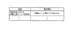
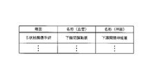
- FIG. FIG. 4 is a conceptual diagram showing an example of a prior information table
- FIG. 13 is a flow chart showing a processing procedure in modification 4-2
- FIG. 16 is a flow chart showing a processing procedure in modification 4-3
- FIG. FIG. 16 is a flow chart showing a processing procedure in modification 4-4
- FIG. FIG. 4 is a conceptual diagram showing an example of a unique name table
- FIG. 21 is an explanatory diagram for explaining an estimation method in Embodiment 7; 20 is a flow chart showing an estimation procedure in Embodiment 7.
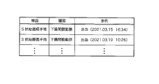
- FIG. FIG. 10 is an explanatory diagram for explaining a method of analyzing calculation results; It is a figure which shows an example of an evaluation coefficient table. It is a figure which shows an example of the calculation result of a score.
- FIG. 13 is a flow chart showing a procedure of processing executed by an information processing apparatus according to an eighth embodiment;
- FIG. FIG. 14 is a sequence diagram showing an example of processing executed by an information processing apparatus according to a ninth embodiment; 4 is a flow chart showing the procedure of processing executed by a first calculation unit; 9 is a flow chart showing a procedure of processing executed by a second calculation unit;
- FIG. 1 is a schematic diagram for explaining a schematic configuration of a surgery support system according to Embodiment 1.
- FIG. 1 is a schematic diagram for explaining a schematic configuration of a surgery support system according to Embodiment 1.
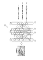
- trocars 10 In laparoscopic surgery, instead of performing an open surgery, a plurality of opening instruments called trocars 10 are attached to the patient's abdominal wall, and through the openings provided in the trocars 10, a laparoscope 11, an energy treatment instrument 12, and forceps 13 are inserted. Insert an instrument into the patient's body.
- the operator uses the energy treatment tool 12 to perform a treatment such as excision of the affected area while viewing an image of the inside of the patient's body (operative field image) captured by the laparoscope 11 in real time.
- Surgical instruments such as the laparoscope 11, the energy treatment instrument 12, and the forceps 13 are held by an operator, a robot, or the like.
- a surgeon is a medical worker involved in laparoscopic surgery, and includes a surgeon, an assistant, a nurse, a doctor who monitors the surgery, and the like.
- the laparoscope 11 includes an insertion section 11A to be inserted into the patient's body, an imaging device 11B built in the distal end portion of the insertion section 11A, an operation section 11C provided in the rear end portion of the insertion section 11A, and a camera control unit (CCU). ) 110 and a universal cord 11D for connecting to the light source device 120.
- the insertion section 11A of the laparoscope 11 is made of a rigid tube.
- a curved portion is provided at the distal end portion of the rigid tube.
- the bending mechanism in the bending section is a well-known mechanism incorporated in a general laparoscope, and is configured to bend in four directions, for example, up, down, left, and right by pulling an operation wire linked to the operation of the operation section 11C.
- the laparoscope 11 is not limited to the flexible scope having a bending portion as described above, and may be a rigid scope having no bending portion, or an imaging device having no bending portion or rigid tube.
- the imaging device 11B includes a solid-state imaging device such as CMOS (Complementary Metal Oxide Semiconductor), a driver circuit including a timing generator (TG), an analog signal processing circuit (AFE), and the like.
- the driver circuit of the imaging device 11B takes in the RGB color signals output from the solid-state imaging device in synchronization with the clock signal output from the TG, and performs necessary processing such as noise removal, amplification, and AD conversion in the AFE. , to generate image data in digital form.
- the driver circuit of the imaging device 11B transmits the generated image data to the CCU 110 via the universal code 11D.
- the operation unit 11C includes an angle lever, a remote switch, and the like operated by the operator.
- the angle lever is an operation tool that receives an operation for bending the bending portion.
- a bending operation knob, a joystick, or the like may be provided instead of the angle lever.
- the remote switch includes, for example, a changeover switch for switching between moving image display and still image display of the observation image, a zoom switch for enlarging or reducing the observation image, and the like.
- the remote switch may be assigned a specific predetermined function, or may be assigned a function set by the operator.
- the operation unit 11C may incorporate a vibrator configured by a linear resonance actuator, a piezo actuator, or the like.
- the CCU 110 vibrates the operation unit 11C by activating the vibrator built in the operation unit 11C to notify the occurrence of the event. You can let the operator know.
- Transmission cables for transmitting control signals output from the CCU 110 to the imaging device 11B and image data output from the imaging device 11B are provided inside the insertion portion 11A, the operation portion 11C, and the universal cord 11D of the laparoscope 11.
- a light guide or the like is arranged to guide the illumination light emitted from the light source device 120 to the distal end portion of the insertion portion 11A. Illumination light emitted from the light source device 120 is guided to the distal end portion of the insertion section 11A through the light guide, and is irradiated onto the surgical field through an illumination lens provided at the distal end portion of the insertion section 11A.
- light source device 120 is described as an independent device in the present embodiment, light source device 120 may be built in CCU 110 .
- the CCU 110 includes a control circuit that controls the operation of the imaging device 11B provided in the laparoscope 11, an image processing circuit that processes image data from the imaging device 11B input through the universal code 11D, and the like.
- the control circuit includes a CPU (Central Processing Unit), a ROM (Read Only Memory), a RAM (Random Access Memory), and the like.
- a control signal is output to the imaging device 11B to control imaging start, imaging stop, zooming, and the like.
- the image processing circuit is equipped with a DSP (Digital Signal Processor), image memory, etc., and performs appropriate processing such as color separation, color interpolation, gain correction, white balance adjustment, and gamma correction on image data input through the universal code 11D. process.
- the CCU 110 generates moving image frame images from the processed image data, and sequentially outputs the generated frame images to the information processing apparatus 200, which will be described later.
- the frame rate of frame images is, for example, 30 FPS (Frames Per Second).
- the CCU 110 may generate video data conforming to a predetermined standard such as NTSC (National Television System Committee), PAL (Phase Alternating Line), DICOM (Digital Imaging and Communication in Medicine). By outputting the generated video data to the display device 130, the CCU 110 can display the operative field image (video) on the display screen of the display device 130 in real time.
- the display device 130 is a monitor including a liquid crystal panel, an organic EL (Electro-Luminescence) panel, or the like. Further, CCU 110 may output the generated video data to recording device 140 and cause recording device 140 to record the video data.
- the recording device 140 includes a recording device such as an HDD (Hard Disk Drive) that records video data output from the CCU 110 together with an identifier identifying each surgery, the date and time of surgery, the location of the surgery, the name of the patient, the name of the operator, and the like.
- HDD Hard Disk Drive
- the information processing device 200 acquires the image data of the operative field image from the CCU 110, and inputs the acquired image data of the operative field image to each of the plurality of learning models, thereby executing calculations by each learning model.
- the information processing apparatus 200 derives an integrated recognition result for the surgical field image from the computation results of the plurality of learning models, and outputs information based on the derived recognition result.
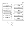
- FIG. 2 is a block diagram for explaining the internal configuration of the information processing device 200.
- the information processing apparatus 200 is a dedicated or general-purpose computer including a control unit 201, a storage unit 202, an operation unit 203, an input unit 204, a first calculation unit 205, a second calculation unit 206, an output unit 207, a communication unit 208, and the like. be.
- the information processing apparatus 200 may be a computer installed in the operating room, or may be a computer installed outside the operating room.
- the information processing apparatus 200 may be a server installed in a hospital where laparoscopic surgery is performed, or may be a server installed outside the hospital.
- the information processing apparatus 200 is not limited to a single computer, and may be a computer system including a plurality of computers and peripheral devices.
- the information processing device 200 may be a virtual machine that is virtually constructed by software.
- the control unit 201 includes, for example, a CPU, ROM, and RAM.
- the ROM included in the control unit 201 stores a control program and the like for controlling the operation of each hardware unit included in the information processing apparatus 200 .
- the CPU in the control unit 201 executes the control program stored in the ROM and various computer programs stored in the storage unit 202, which will be described later, and controls the operation of each hardware unit, so that the entire apparatus can perform the information processing according to the present application. function as a device.
- the RAM provided in the control unit 201 temporarily stores data and the like that are used during execution of calculations.
- control unit 201 is configured to include a CPU, a ROM, and a RAM. Programmable Gate Array), quantum processor, volatile or non-volatile memory, etc. Further, the control unit 201 may have functions such as a clock that outputs date and time information, a timer that measures the elapsed time from when a measurement start instruction is given until a measurement end instruction is given, and a counter that counts the number of good.
- the storage unit 202 includes a storage device such as a hard disk and flash memory.
- the storage unit 202 stores a computer program executed by the control unit 201, various data acquired from the outside, various data generated inside the apparatus, and the like.
- the computer programs stored in the storage unit 202 include a recognition processing program PG1 that causes the control unit 201 to execute processing for recognizing a recognition target included in the operative field image, and a recognition processing program PG1 that causes the display device 130 to display information based on the recognition result. and a display processing program PG2 for causing the control unit 201 to execute the processing of .
- the recognition processing program PG1 and the display processing program PG2 do not need to be independent computer programs, and may be implemented as one computer program.
- These programs are provided, for example, by a non-temporary recording medium M on which computer programs are readable.
- the recording medium M is a portable memory such as a CD-ROM, a USB memory, and an SD (Secure Digital) card.
- the control unit 201 uses a reading device (not shown) to read a desired computer program from the recording medium M, and stores the read computer program in the storage unit 202 .
- the computer program may be provided by communication.
- the control unit 201 may download a desired computer program through the communication unit 208 and store the downloaded computer program in the storage unit 202 .
- the storage unit 202 has a first learning model 310 and a second learning model 320 .
- the first learning model 310 is a learned learning model trained to output information about the first organ included in the operative field image in response to the input of the operative field image.
- the first organ is a specific organ such as esophagus, stomach, large intestine, pancreas, spleen, ureter, lung, prostate, uterus, gallbladder, liver, vas deferens, or connective tissue, fat, nerve, blood vessel, muscle, membranous. Includes non-specific organs such as structures.
- the first organ is not limited to a specific organ, and may be any structure existing in the body.
- the second learning model 320 is a learned learning model trained to output information about the second organ included in the operative field image according to the input of the operative field image.
- the second organ includes the specific organ or non-specific organ described above.
- the second organ is not limited to a specific organ, and may be any structure existing within the body. In the following description, when there is no need to distinguish between a specific organ and a non-specific organ, they are simply referred to as an organ.
- the second organ to be recognized has characteristics similar to those of the first organ, and an organ that may be misidentified as the first organ in recognition processing is selected.
- the recognition target of the first learning model 310 is the loose connective tissue
- the neural tissue (or membrane structure) is selected as the recognition target of the second learning model 320 .
- the combination of the first organ and the second organ is not limited to (a) loose connective tissue and nerve tissue (or membranous structures), (b) fat and pancreas, (c) fat to be excised and fat to be preserved, (d) two of hemorrhages, scars, and blood vessels; (e) two of ureters, arteries, and membranous structures; (f) stomach and intestine; (g) liver and spleen; There may be.
- the first learning model 310 is trained to output information about the loose connective tissue included in the operative field image in accordance with the input of the operative field image.
- a first learning model 310 includes an operative field image obtained by imaging the operative field, and correct data indicating the first organ portion (the loose connective tissue portion in the first embodiment) in the operative field image. Training data is generated by learning using an appropriate learning algorithm. The correct data indicating the first organ portion is generated by manual annotation by a specialist such as a doctor. The same is true for the second learning model 320 as well.
- the first and second learning models 310, 320 may be generated inside the information processing device 200, or may be generated by an external server. In the latter case, the information processing apparatus 200 downloads the first and second learning models 310 and 320 generated by the external server through communication, and stores the downloaded first and second learning models 310 and 320 in the storage unit 202. It should be memorized.
- the storage unit 202 as definition information of the first and second learning models 310 and 320, information of layers included in the first and second learning models 310 and 320, information of nodes constituting each layer, weight coefficients between nodes and information such as parameters determined by learning such as bias.
- the operation unit 203 includes operation devices such as a keyboard, mouse, touch panel, non-contact panel, stylus pen, and voice input using a microphone.
- the operation unit 203 receives an operation by an operator or the like, and outputs information regarding the received operation to the control unit 201 .
- the control unit 201 executes appropriate processing according to operation information input from the operation unit 203 .
- information processing apparatus 200 is configured to include operation unit 203, but may be configured to receive operations through various devices such as CCU 110 connected to the outside.
- the input unit 204 has a connection interface for connecting input devices.
- the input device connected to input unit 204 is CCU 110 .
- the input unit 204 receives image data of an operating field image captured by the laparoscope 11 and processed by the CCU 110 .
- the input unit 204 outputs input image data to the control unit 201 .
- the control unit 201 may cause the storage unit 202 to store the image data acquired from the input unit 204 .
- Image data of the operative field image may be obtained from an image processing device (not shown) that is detachably attached to the device.
- the information processing device 200 may also acquire image data of the operative field image recorded in the recording device 140 .
- the first computing unit 205 includes a processor, memory, and the like.
- An example of a processor is GPU (Graphics Processing Unit) and an example of memory is VRAM (Video RAM).
- the first calculation unit 205 executes the calculation by the first learning model 310 with the built-in processor and outputs the calculation result to the control unit 201 .
- the first calculation unit 205 draws an image to be displayed on the display device 130 on the built-in memory in accordance with an instruction from the control unit 201, and outputs the image to the display device 130 through the output unit 207, thereby obtaining a desired image. is displayed on the display device 130 .
- the second computing unit 206 like the first computing unit 205, includes a processor, memory, and the like.
- the second calculation unit 206 may be equivalent to the first calculation unit 205 or may have a lower calculation capability than the first calculation unit 205 .
- the second calculation unit 206 executes the calculation by the second learning model 320 with the built-in processor and outputs the calculation result to the control unit 201 .
- the second calculation unit 206 draws an image to be displayed on the display device 130 on the built-in memory in accordance with an instruction from the control unit 201, and outputs the image to the display device 130 through the output unit 207, thereby obtaining a desired image. is displayed on the display device 130 .
- the output unit 207 includes a connection interface for connecting output devices.
- the output device connected to the output unit 207 is the display device 130 .
- the control unit 201 When the control unit 201 generates information to be notified to the operator or the like, such as integrated recognition results derived from the calculation results of the learning models 310 and 320, the control unit 201 outputs the generated information from the output unit 207 to the display device 130. By doing so, information is displayed on the display device 130 .
- the output unit 207 may output information to be notified to the operator or the like by voice or sound.
- the communication unit 208 has a communication interface for transmitting and receiving various data.
- the communication interface provided in the communication unit 208 is a communication interface conforming to a wired or wireless communication standard used in Ethernet (registered trademark) or WiFi (registered trademark).
- Ethernet registered trademark
- WiFi registered trademark
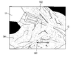
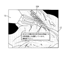
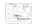
- FIG. 3 is a schematic diagram showing an example of an operating field image.
- the operative field image in the present embodiment is an image obtained by imaging the inside of the patient's abdominal cavity with the laparoscope 11 .
- the operative field image does not need to be a raw image output by the imaging device 11B of the laparoscope 11, and may be an image (frame image) processed by the CCU 110 or the like.
- the operative field imaged by the laparoscope 11 includes specific organs, tissues constituting blood vessels, nerves, etc., connective tissues existing between tissues, tissues including lesions such as tumors, and membranes and layers covering the tissues. organization is included. While grasping the relationship between these anatomical structures, the operator uses surgical tools such as the energy treatment tool 12 and the forceps 13 to dissect the tissue including the lesion.
- the surgical field image shown as an example in FIG. A scene in which tissue 502 is about to be peeled is shown.
- the loose connective tissue 502 is a fibrous connective tissue that fills between tissues and organs, and has a relatively small amount of fibers (elastic fibers) constituting the tissue.
- the loose connective tissue 502 is peeled off as necessary when expanding the organ 501 or excising a lesion.
- the loose connective tissue 502 runs vertically (in the direction of the white arrow in the figure), and the nerve tissue 503 runs in the horizontal direction (indicated by the black arrow in the figure) so as to intersect the loose connective tissue 502. direction).
- Loose connective tissue is a tissue that is detached as needed, but if nerves are damaged during the process of traction or detachment, functional impairment may occur after surgery. For example, damage to the hypogastric nerve in colon surgery can cause dysuria. Damage to the recurrent laryngeal nerve during esophagectomy or pulmonary resection can also cause dysphagia. For this reason, it would be useful for the operator if information on the results of recognition of loose connective tissue and nerve tissue could be provided to the operator.
- the information processing apparatus 200 executes calculation by the first learning model 310 and calculation by the second learning model 320 for the same operative field image, and calculates an operative field image from the two calculation results. By deriving an integrated recognition result and outputting information based on the derived recognition result, information on loose connective tissue and nerve tissue is provided to the operator.
- FIG. 4 is a schematic diagram showing a configuration example of the first learning model 310.
- the first learning model 310 is a learning model for performing image segmentation, and is constructed by a neural network with convolutional layers such as SegNet, for example.
- the learning model 310 is not limited to SegNet, but is constructed using any neural network that can perform image segmentation, such as FCN (Fully Convolutional Network), U-Net (U-Shaped Network), PSPNet (Pyramid Scene Parsing Network). good too.
- the learning model 310 may be constructed using a neural network for object detection such as YOLO (You Only Look Once) or SSD (Single Shot Multi-Box Detector) instead of the neural network for image segmentation.
- the calculation by the first learning model 310 is executed in the first calculation unit 205.
- the first computation unit 205 performs computation according to the definition information of the first learning model 310 including learned parameters.
- the first learning model 310 comprises an encoder 311, a decoder 312, and a softmax layer 313, for example.
- the encoder 311 is configured by alternately arranging convolution layers and pooling layers.
- the convolution layers are multi-layered into 2 to 3 layers. In the example of FIG. 4, the convolutional layers are shown without hatching, and the pooling layers are shown with hatching.
- the convolution layer performs a convolution operation between the input data and a filter of a predetermined size (for example, 3 ⁇ 3, 5 ⁇ 5, etc.). That is, the input value input to the position corresponding to each element of the filter is multiplied by the weighting factor preset in the filter for each element, and the linear sum of the multiplied values for each element is calculated.
- the output in the convolutional layer is obtained by adding the set bias to the calculated linear sum.
- the result of the convolution operation may be transformed by an activation function.
- ReLU Rectified Linear Unit
- the output of the convolutional layer represents a feature map that extracts the features of the input data.
- the pooling layer calculates the local statistics of the feature map output from the convolution layer, which is the upper layer connected to the input side. Specifically, a window of a predetermined size (for example, 2 ⁇ 2, 3 ⁇ 3) corresponding to the position of the upper layer is set, and local statistics are calculated from the input values within the window. For example, the maximum value can be used as the statistic.
- the size of the feature map output from the pooling layer is reduced (downsampled) according to the size of the window.
- the encoder 311 successively repeats the operations in the convolution layer and the operation in the pooling layer, thereby converting the input image of 224 pixels ⁇ 224 pixels into 112 ⁇ 112, 56 ⁇ 56, 28 ⁇ 28, . It shows that the feature map is sequentially down-sampled to a ⁇ 1 feature map.
- the output of the encoder 311 (1 ⁇ 1 feature map in the example of FIG. 4) is input to the decoder 312 .
- the decoder 312 is composed of alternating deconvolution layers and depooling layers.
- the deconvolution layers are multi-layered in 2 to 3 layers. In the example of FIG. 4, the deconvolution layers are shown without hatching, and the depooling layers are shown with hatching.
- the input feature map is deconvolved.
- the deconvolution operation is an operation to restore the feature map before the convolution operation under the presumption that the input feature map is the result of the convolution operation using a specific filter.
- a specific filter is represented by a matrix
- the product of the transposed matrix for this matrix and the input feature map is calculated to generate a feature map for output.
- the operation result of the deconvolution layer may be transformed by an activation function such as ReLU described above.
- the inverse pooling layers included in the decoder 312 are individually associated one-to-one with the pooling layers included in the encoder 311, and the associated pairs have substantially the same size.
- the inverse pooling layer again enlarges (upsamples) the size of the feature map downsampled in the pooling layer of the encoder 311 .
- the example of FIG. 4 sequentially upsamples to 1 ⁇ 1, 7 ⁇ 7, 14 ⁇ 14, . indicates that
- the output of decoder 312 (224 ⁇ 224 feature map in the example of FIG. 4) is input to softmax layer 313 .
- the softmax layer 313 outputs the probability of the label identifying the site at each position (pixel) by applying the softmax function to the input values from the deconvolution layer connected to the input side.
- the first learning model 310 may output, from the softmax layer 313, the probability indicating whether or not each pixel corresponds to loose connective tissue with respect to the input of the surgical field image.
- a calculation result by the first learning model 310 is output to the control unit 201 .
- An image (recognition image) showing the recognition result of the loose connective tissue portion is obtained by extracting pixels whose label probability output from the softmax layer 313 is equal to or greater than a threshold value (for example, 60% or greater).
- the first calculation unit 205 draws the recognition image of the loose connective tissue portion in the built-in memory (VRAM) and outputs the recognition result of the first learning model 310 to the display device 130 through the output unit 207. 130 may be displayed.
- the recognition image is an image of the same size as the operative field image, and is generated as an image in which pixels recognized as loose connective tissue are assigned specific colors.
- the color assigned to the pixels of the loose connective tissue is preferably a color that does not exist inside the human body so that it can be distinguished from organs, blood vessels, and the like.
- the color that does not exist inside the human body is, for example, a cold (blue) color such as blue or light blue.
- information indicating the degree of transparency is added to each pixel constituting the recognition image, and a non-transparent value is set for pixels recognized as loose connective tissue, and a transparent value is set for other pixels.
- an image of 224 pixels ⁇ 224 pixels is used as the input image to the first learning model 310, but the size of the input image is not limited to the above. , can be appropriately set according to the size of the operative field image obtained from the laparoscope 11 and the like. Also, the input image to the first learning model 310 does not have to be the entire operative field image obtained from the laparoscope 11, and may be a partial image generated by cutting out the region of interest of the operative field image. A region of interest that includes a treatment target is often located near the center of the operative field image. may be used. By reducing the size of the image input to the first learning model 310, it is possible to improve the recognition accuracy while increasing the processing speed.
- FIG. 5 is a schematic diagram showing a configuration example of the second learning model 320.
- the second learning model 320 includes an encoder 321, a decoder 322, and a softmax layer 323, and is configured to output information about neural tissue portions contained in the surgical field image in response to the input of the surgical field image.
- the configurations of the encoder 321, the decoder 322, and the softmax layer 323 included in the second learning model 320 are the same as those of the first learning model 310, so detailed description thereof will be omitted.
- the calculation by the second learning model 320 is executed in the second calculation unit 206.
- the second computation unit 206 performs computation according to the definition information of the second learning model 320 including learned parameters.
- the second learning model 320 according to Embodiment 1 may output, from the softmax layer 323, the probability indicating whether or not each pixel corresponds to nerve tissue with respect to the input of the surgical field image.
- a calculation result by the second learning model 320 is output to the control unit 201 .
- an image (recognition image) showing the recognition result of the neural tissue portion is obtained.
- the second calculation unit 206 draws the recognition image of the nerve tissue part in the built-in memory (VRAM) and outputs the recognition result of the second learning model 320 to the display device 130 by outputting it to the display device 130 through the output unit 207. may be displayed.
- the structure of the recognition image showing nerve tissue is similar to that of loose connective tissue, but the color assigned to the pixels of nerve tissue is a color that distinguishes it from loose connective tissue (for example, green or yellow). color).
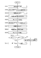
- FIG. 6 is a flow chart showing the procedure of processing executed by the information processing apparatus 200 according to the first embodiment.
- the control unit 201 of the information processing apparatus 200 reads out the recognition processing program PG1 and the display processing program PG2 from the storage unit 202 and executes them, thereby performing processing according to the following procedure.
- the operative field image obtained by imaging the operative field with the imaging device 11B of the laparoscopic 11 is output to the CCU 110 through the universal code 11D at any time.
- the control unit 201 of the information processing apparatus 200 acquires, from the input unit 204, the surgical field image in frame units output from the CCU 110 (step S101).
- the control unit 201 executes the following processing each time a surgical field image is acquired in units of frames.
- the control unit 201 sends the surgical field image in units of frames acquired through the input unit 204 to the first calculation unit 205 and the second calculation unit 206, and instructs the first calculation unit 205 and the second calculation unit 206 to perform calculation.
- a start instruction is given (step S102).
- the first calculation unit 205 executes calculation by the first learning model 310 (step S103). That is, the first computing unit 205 generates a feature map from the input surgical field image, performs computation by the encoder 311 that sequentially down-samples the generated feature map, and performs computation by the encoder 311 that sequentially up-samples the feature map input from the encoder 311. 312 and a softmax layer 313 that identifies each pixel of the feature map finally obtained from the decoder 312 .
- the first calculation unit 205 outputs the calculation result of the learning model 310 to the control unit 201 (step S104).
- the second calculation unit 206 executes calculation by the second learning model 320 (step S105). That is, the second calculation unit 206 generates a feature map from the input surgical field image, performs calculation by the encoder 321 that sequentially down-samples the generated feature map, and performs calculation by the encoder 321 that sequentially up-samples the feature map input from the encoder 321. 322 and a softmax layer 323 that identifies each pixel of the feature map finally obtained from the decoder 322 .
- the second calculation unit 206 outputs the calculation result of the learning model 320 to the control unit 201 (step S106).
- the procedure of executing the calculation by the second calculation unit 206 after the calculation by the first calculation unit 205 is performed. is preferably performed concurrently with the calculation by .
- the control unit 201 derives an integrated recognition result for the operative field image based on the computation result of the first learning model 310 and the computation result of the second learning model 320. Specifically, the control unit 201 executes the following processes.
- the control unit 201 refers to the calculation result of the first learning model 310 and executes the process of recognizing the loose connective tissue (step S107).
- the control unit 201 extracts pixels whose labels output from the softmax layer 313 of the first learning model 310 have a probability equal to or higher than a threshold value (for example, 60% or higher), thereby extracting loose connective tissue included in the surgical field image. can recognize.
- a threshold value for example, 60% or higher
- the control unit 201 refers to the calculation result of the second learning model 320 and executes the neural tissue recognition process (step S108).
- the control unit 201 extracts pixels whose labels output from the softmax layer 323 of the second learning model 320 have a probability of a threshold value or more (for example, 60% or more), thereby recognizing nerve tissue included in the operative field image. be able to.
- the control unit 201 determines whether or not the recognition result of the loose connective tissue overlaps with the recognition result of the neural tissue (step S109). In this step, it is checked whether a specific structure contained in the operative field image is recognized as loose connective tissue on the one hand and nerve tissue on the other hand. Specifically, when one pixel in the surgical field image is recognized as loose connective tissue on one side and nerve tissue on the other side, the control unit 201 determines that the recognition results overlap. Alternatively, a region in the operating field image recognized as loose connective tissue and a region in the operating field image recognized as nerve tissue may be compared to determine overlap of recognition results.
- the area ratio of the overlap between the two is a predetermined ratio or more (for example, 40% or more)
- it is determined that the recognition results overlap and if the area ratio is less than the predetermined ratio, it is determined that the recognition results do not overlap. good.
- the control unit 201 When it is determined that the recognition results do not overlap (S109: NO), the control unit 201 outputs the loose connective tissue recognition result and the neural tissue recognition result (step S110). Specifically, the control unit 201 instructs the first calculation unit 205 to superimpose the recognition image of the loose connective tissue on the surgical field image, and instructs the second calculation unit 206 to , the recognized image of the nerve tissue is superimposed on the operative field image. The first calculation unit 205 and the second calculation unit 206 draw the recognition images of the loose connective tissue and the nerve tissue in the built-in VRAM according to the instruction from the control unit 201, and output the images to the display device 130 through the output unit 207. By outputting, the recognition images of loose connective tissue and nerve tissue are superimposed on the surgical field image and displayed.
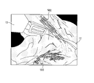
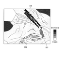
- FIG. 7 is a schematic diagram showing a display example of recognition results in the first embodiment.
- the portion recognized as the loose connective tissue 502 is shown as a hatched region
- the portion recognized as the nerve tissue 503 is shown as another hatched region for the convenience of drawing. It is shown.
- pixels recognized as loose connective tissue 502 are displayed in, for example, a blue color
- pixels recognized as nerve tissue 503 are displayed, for example, in a green color.
- the operator can distinguish between the loose connective tissue 502 and the nerve tissue 503, and can recognize, for example, the presence of the nerve tissue 503 that should not be damaged.
- the energy treatment device 12 can be used to ablate the loose connective tissue 502 .
- both the loose connective tissue recognized based on the calculation result of the first calculation unit 205 and the nerve tissue recognized based on the calculation result of the second calculation unit 206 are displayed.
- a configuration in which only one of them is displayed may be used.
- the tissue to be displayed may be selected by the operator, or may be switched by the operator's operation.
- step S109 of the flowchart shown in FIG. 6 when it is determined that the recognition results overlap (S109: YES), the control unit 201 outputs warning information indicating that a similar structure has been recognized (step S111).
- FIG. 8 is a schematic diagram showing a display example of warning information according to the first embodiment.
- FIG. 8 shows a warning when the structure 504 included in the operative field image is recognized as loose connective tissue based on the calculation result of the first calculation unit 205, and as nerve tissue based on the calculation result of the second calculation unit 206.
- An example of information display is shown.
- the first learning model 310 used by the first computation unit 205 is trained to output information on loose connective tissue in accordance with the input of the operative field image
- the second learning model 320 used by the second computation unit 206 is trained to output information about nerve tissue according to the input of the operative field image. If recognition processing is performed independently using the models 310 and 320, recognition results may overlap.
- the control unit 201 can prompt the operator for confirmation by displaying warning information as shown in FIG.
- control unit 201 is configured to display text information indicating a warning superimposed on the surgical field image.
- text information indicating the warning may be displayed on another display device (not shown).
- the control unit 201 may display a graphic indicating a warning, or issue a warning by outputting voice or sound instead of displaying text information indicating a warning.
- the control unit 201 of the information processing device 200 selects the recognition result with the higher degree of certainty. to output information based on the selected recognition result.
- the certainty factor of the recognition result by the first learning model 310 is calculated based on the probability output from the softmax layer 313 .
- the control unit 201 may calculate the degree of certainty by averaging probability values for each pixel recognized as loose connective tissue. The same applies to the certainty factor of the recognition result by the second learning model 320 . For example, as a result of recognizing the structure 504 shown in FIG. If the structure 504 is recognized as a nerve tissue with a certainty of %, the control unit 201 should present the recognition result that the structure 504 is a loose connective tissue to the operator.
- FIG. 9 is a schematic diagram showing a display example of a recognition result according to certainty. For example, as a result of recognizing the structure 505 included in the operative field image by the first learning model 310, it is recognized as a loose connective tissue with a certainty of 95%, and the same structure 505 is recognized by the second learning model 320.
- the control unit 201 colors this structure 505 in, for example, a blue-based color (black in the drawing) and presents it to the operator.
- the control unit 201 colors this structure 506 with, for example, a greenish color (white on the drawing) and presents it to the operator.
- the control unit 201 colors this structure 507 with, for example, an intermediate color between blue and green colors (gray on the drawing), and displays it to the operator.
- a configuration that changes saturation, transparency, etc. may be employed.
- Modification 1-4 When a structure recognized as a loose connective tissue and a structure recognized as a nerve tissue exist in the operative field image, the control unit 201 of the information processing apparatus 200 determines that both structures Information such as appropriate positional relationships of bodies, distances to feature points, distances to other structures, areas of other structures, etc. may be derived.
- Embodiment 1 based on the calculation result of the first learning model 310 and the calculation result of the second learning model 320, the integrated recognition result of the organs included in the surgical field is acquired. can be done.
- the information processing apparatus 200 issues a warning or stops outputting information when recognition results for similar structures are duplicated, thereby avoiding presenting results that may be erroneous in recognition to the operator. can.
- the information processing apparatus 200 includes a first learning model 310 for recognizing organs and a third learning model 330 for recognizing events.
- the organ recognized by the first learning model 310 is not limited to loose connective tissue, and may be a preset organ.
- Events recognized by the third learning model 330 are events such as bleeding, injury, and pulsation. Since other configurations of the information processing apparatus 200 are the same as those of the first embodiment, description thereof will be omitted.
- FIG. 10 is a schematic diagram showing a configuration example of the third learning model 330.
- the third learning model 330 includes an encoder 331, a decoder 332, and a softmax layer 333, and is configured to output information about events occurring in the operative field image in response to the input of the operative field image.
- Information related to events output by the third learning model 330 is information related to events such as bleeding, damage (burns caused by the energy treatment device 12), and pulsation.
- the third learning model 330 is not limited to learning models for image segmentation and object detection, but also CNN (Convolutional Neural Networks), RNN (Recurrent Neural Networks), LSTM (Long Short Term Memory), GAN (Generative Adversarial Network), etc. It may be a learning model.
- the calculation by the third learning model 330 is executed in the second calculation unit 206.
- the second calculation unit 206 performs calculation according to the definition information of the third learning model 330 including learned parameters.
- the third learning model 330 may output from the softmax layer 333 the probability indicating whether or not an event has occurred with respect to the input of the surgical field image.
- a calculation result by the third learning model 330 is output to the control unit 201 .
- the control unit 201 determines that an event has occurred in the surgical field image when the probability of the label output from the softmax layer 333 is greater than or equal to a threshold value (for example, 60% or greater).
- the control unit 201 may determine whether an event has occurred in units of pixels of the surgical field image, or may determine whether an event has occurred in units of the surgical field image.
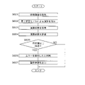
- FIG. 11 is a flow chart showing the procedure of processing executed by the information processing apparatus 200 according to the second embodiment.
- the information processing apparatus 200 executes steps S201 to S206 in the same manner as in the first embodiment each time a surgical field image is acquired.
- the control unit 201 of the information processing apparatus 200 acquires the calculation result of the first learning model 310 and the calculation result of the third learning model 330, and based on these calculation results, the integrated recognition result of the surgical field image. to derive Specifically, the control unit 201 executes the following processes.
- the control unit 201 refers to the calculation result of the first learning model 310 and executes organ recognition processing (step S207).
- the control unit 201 extracts pixels whose label probability output from the softmax layer 313 of the first learning model 310 is equal to or greater than a threshold value (e.g., 60% or greater), thereby recognizing the organ included in the operative field image. can be done.
- a threshold value e.g. 60% or greater
- the control unit 201 refers to the calculation result of the third learning model 330 and executes event recognition processing (step S208).
- the control unit 201 can determine whether an event has occurred for each pixel by extracting pixels whose label probability output from the softmax layer 333 of the third learning model 330 is equal to or greater than a threshold (for example, 60% or greater).
- the control unit 201 determines whether an event has occurred in the organ recognized in step S207 (step S209).
- the control unit 201 compares the pixels recognized as the organ in step S207 with the pixels recognized as the occurrence of the event in step S208, and if they match, determines that the event occurred in the recognized organ. .
- control unit 201 When it is determined that no event has occurred in the recognized organ (S209: NO), the control unit 201 terminates the processing according to this flowchart. Note that the control unit 201 may individually display the recognition result of the organ without associating it with the event, or may display the recognition result of the event individually without associating it with the organ.
- the control unit 201 When it is determined that an event has occurred in the recognized organ (S209: YES), the control unit 201 outputs information on the organ in which the event occurred (step S210). For example, the control unit 201 may display the name of the organ in which the event occurred as text information superimposed on the operative field image. Instead of superimposed display on the operative field image, the name of the organ in which the event occurred may be displayed outside the operative field image, or may be output by sound or voice.
- FIG. 12 is a schematic diagram showing a display example of recognition results in the second embodiment.
- the display example of FIG. 12 shows an example in which character information to the effect that bleeding has occurred from the surface of the stomach is displayed superimposed on the surgical field image.
- the control unit 201 may display information about an organ damaged by the energy treatment device 12 or the like, and may display information about an organ in which pulsation is occurring, without being limited to the bleeding organ.
- the organ may be displayed blinking in synchronization with the pulsation. Synchronization does not necessarily have to perfectly match the pulsation, and may be a periodic display close to the pulsation.
- the control unit 201 When the control unit 201 recognizes bleeding from a specific organ (for example, an important blood vessel), the data of the patient's vital signs (pulse, blood pressure, respiration, body temperature) constantly detected by a sensor (not shown) is collected. The data may be acquired as needed and the acquired data may be displayed on the display device 130 . Further, when the control unit 201 recognizes bleeding from a specific organ (for example, important blood vessels), the control unit 201 may notify the external device through the communication unit 208 .
- the notification destination external device may be a terminal carried by an anesthesiologist, or may be an in-hospital server or the like that supervises and manages events in the hospital.
- control unit 201 when the control unit 201 recognizes bleeding from an organ, the control unit 201 may change the threshold used in organ recognition or stop organ recognition. Furthermore, when the control unit 201 recognizes bleeding from an organ, it may become difficult to recognize the organ. Therefore, the control unit 201 switches to a learning model (not shown) improved for bleeding, and continues organ recognition using this learning model. You may
- control unit 201 may automatically estimate the amount of bleeding or the bleeding rate and suggest blood transfusion.
- the control unit 201 can estimate the bleeding amount by calculating the bleeding area on the image, and can estimate the bleeding rate by calculating the time change of the bleeding area.
- an integrated recognition result obtained by combining the learning model 310 for organ recognition and the learning model 320 for event recognition can be presented to the operator.
- Embodiment 3 will describe a configuration for deriving an integrated recognition result by combining organ recognition and device recognition.
- the information processing apparatus 200 includes a first learning model 310 for recognizing organs and a fourth learning model 340 for recognizing devices.
- the organ recognized by the first learning model 310 is not limited to loose connective tissue, and may be a preset organ.
- Devices recognized by the fourth learning model 340 are surgical tools used during surgery, such as the energy treatment tool 12 and the forceps 13 . Since other configurations of the information processing apparatus 200 are the same as those of the first embodiment, description thereof will be omitted.
- FIG. 13 is a schematic diagram showing a configuration example of the fourth learning model 340.
- the fourth learning model 340 includes an encoder 341, a decoder 342, and a softmax layer 343, and is configured to output information about devices included in the operative field image in response to the input of the operative field image.
- the device-related information output by the fourth learning model 340 is information related to surgical tools used during surgery, such as the energy treatment tool 12 and the forceps 13 .
- the fourth learning model 340 is not limited to a learning model for image segmentation or object detection, and may be a learning model based on CNN, RNN, LSTM, GAN, or the like.
- a plurality of fourth learning models 340 may be prepared according to the type of device.
- the calculation by the fourth learning model 340 is executed in the second calculation unit 206.
- the second calculation unit 206 performs calculation according to the definition information of the fourth learning model 340 including learned parameters.
- the fourth learning model 340 may output from the softmax layer 343 probabilities indicating whether or not each pixel corresponds to a specific device with respect to the input of the surgical field image.
- a calculation result by the fourth learning model 340 is output to the control unit 201 .
- the control unit 201 determines that a specific device included in the operative field image has been recognized.
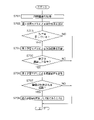
- FIG. 14 is a flow chart showing the procedure of processing executed by the information processing apparatus 200 according to the third embodiment.
- the information processing apparatus 200 executes steps S301 to S306 in the same manner as in the first embodiment each time a surgical field image is acquired.
- the control unit 201 of the information processing apparatus 200 acquires the calculation result of the first learning model 310 and the calculation result of the fourth learning model 340, and based on these calculation results, the integrated recognition result of the surgical field image. to derive Specifically, the control unit 201 executes the following processes. It is assumed that the storage unit 202 stores information on organs and information on devices recognized in the most recent (for example, one frame previous) surgical field image.
- the control unit 201 refers to the calculation result of the first learning model 310 and executes organ recognition processing (step S307).
- the control unit 201 extracts pixels whose label probability output from the softmax layer 313 of the first learning model 310 is equal to or greater than a threshold value (e.g., 60% or greater), thereby recognizing the organ included in the operative field image. can be done.
- a threshold value e.g. 60% or greater
- the control unit 201 refers to the calculation result of the fourth learning model 340 and executes device recognition processing (step S308).
- the control unit 201 extracts pixels whose labels output from the softmax layer 343 of the fourth learning model 340 have a probability of a threshold value or more (for example, 60% or more), thereby recognizing devices included in the operative field image. can be done.
- the control unit 201 determines whether the device is moving over the organ recognized in step S307 (step S309).
- the control unit 201 reads from the storage unit 202 the information on the organ and device recognized from the most recent operative field image, compares the read information on the organ and device with the information on the newly recognized organ and device, By detecting a change in position, it can be determined whether the device is moving over the organ.
- control unit 201 When determining that the device has not moved on the organ (S309: NO), the control unit 201 terminates the processing according to this flowchart. Note that the control unit 201 may display the recognition result of the organ regardless of the device, or may display the recognition result of the device regardless of the organ.
- the control unit 201 If it is determined that the device is moving on the organ (S309: YES), the control unit 201 generates display data in which the display mode of the organ is changed, and outputs the data to the display device 130 through the output unit 207 (step S310). ).
- the control unit 201 may change the display mode by changing the display color, saturation, and transparency of the organ, or may change the display mode by blinking the organ.
- the display device 130 displays the organ whose display mode has been changed.
- the information processing apparatus 200 may misrecognize the organ. Therefore, by changing the display mode and displaying, the operator can be prompted to make a decision.
- the control unit 201 may instruct the first calculation unit 205 to change the display mode, and the display mode may be changed by the processing of the first calculation unit 205 .
- the organ recognition process may be stopped.
- the control unit 201 may continuously perform the device recognition process and restart the organ recognition process at the timing when it is determined that the device has stopped.
- control unit 201 of the information processing apparatus 200 may stop outputting the recognition result of the organ.
- the calculations by the first learning model 310 and the fourth learning model 340, the organ recognition processing based on the calculation results of the first learning model 310, and the device recognition processing based on the calculation results of the fourth learning model 340 are continuously performed. is executed, and the display of the recognition image indicating the recognition result of the organ is stopped.
- the control unit 201 may restart the output process when it determines that the device has stopped.
- the control unit 201 of the information processing apparatus 200 may derive information on the organ being processed by the device based on the organ recognition processing and the device recognition processing.
- the control unit 201 can derive information on the organ being processed by the device by comparing the pixels recognized as the organ in step S307 and the pixels recognized as the device in step S308.
- the control unit 201 may output the information of the organ being processed by the device and display it on the display device 130, for example.
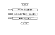
- the control unit 201 of the information processing apparatus 200 may acquire dimension information of the recognized device and derive dimension information of the recognized organ based on the acquired dimension information of the device.
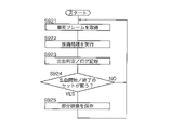
- FIG. 15 is a flowchart showing the procedure for deriving dimension information.
- the control unit 201 acquires dimension information of the recognized device (step S321).
- the device dimension information may be stored in advance in the storage unit 202 of the information processing apparatus 200, or may be stored in an external device. In the former case, the control unit 201 may acquire dimension information by reading desired information from the storage unit 202, and in the latter case, the control unit 201 may acquire dimension information by accessing an external device. Note that the dimension information does not have to be the dimensions of the entire device, and may be the dimensions of a portion of the device (for example, the cutting edge portion).
- the control unit 201 calculates the ratio between the size of the image information of the device portion indicated by the acquired size information and the size of the recognized organ on the image (step S322).
- the control unit 201 calculates the dimensions of the organ based on the device dimension information acquired in step S321 and the dimension ratio calculated in step S322 (step S323).
- the control unit 201 may output the calculated dimension information of the organ and display it on the display device 130, for example.
- the control unit 201 of the information processing apparatus 200 may derive information on the organ damaged by the device based on the organ recognition processing and the device recognition processing. For example, when the control unit 201 recognizes a device on an organ and determines that a part of the organ has changed color, it determines that damage to the organ caused by the device has been detected. A device on an organ is recognized by a procedure similar to that shown in the flow chart of FIG. Discoloration of an organ is recognized by changes in pixel values over time. When the control unit 201 detects organ damage caused by the device, the control unit 201 outputs information to that effect and causes the display device 130 to display the information, for example.
- the control unit 201 of the information processing apparatus 200 may derive information indicating whether or not the device used for the organ is appropriate based on the organ recognition processing and the device recognition processing.
- the storage unit 202 of the information processing apparatus 200 has a definition table that defines the relationship between the types of organs and devices that can be used (or devices that should not be used) for each organ. This definition table defines, for example, that sharp forceps should not be used for the intestinal tract.
- the control unit 201 recognizes the organ and device from the operative field image, and refers to the definition table described above to determine whether the device used for the organ is appropriate.
- control unit 201 If it is determined to be inappropriate (for example, sharp forceps are being used for the intestinal tract), the control unit 201 outputs information indicating that an incorrect device is being used, and displays it on the display device 130, for example. Let Also, the control unit 201 may issue a warning by voice or warning sound.
- the control unit 201 of the information processing apparatus 200 may output the operation support information of the device and display it on the display device 130, for example.
- the device operation support information is a device usage manual, and may be stored in the storage unit 202 of the information processing apparatus 200 or an external device.
- an integrated recognition result obtained by combining the learning model 310 for organ recognition and the learning model 340 for device recognition can be presented to the operator.
- Embodiment 4 will describe a configuration for deriving an integrated recognition result by combining organ recognition and scene recognition.
- the information processing apparatus 200 includes a first learning model 310 for recognizing organs and a fifth learning model 350 for recognizing scenes.
- the organ recognized by the first learning model 310 is not limited to loose connective tissue, and may be a preset organ.
- a model may be prepared for each type of organ so as to correspond to various organs.
- a scene recognized by the fifth learning model 350 is, for example, a characteristic scene indicating a characteristic scene of surgery. Since other configurations of the information processing apparatus 200 are the same as those of the first embodiment, description thereof will be omitted.
- FIG. 16 is a schematic diagram showing a configuration example of the fifth learning model 350.
- the fifth learning model 350 includes an input layer 351, an intermediate layer 352, and an output layer 353, and is configured to output information about the scene indicated by the surgical field image in response to the surgical field image input.
- the information about the scene output by the fifth learning model 350 includes the probability that the scene includes specific organs such as blood vessels, important nerves, and specific organs (ureter, spleen, etc.), blood vessel dissection, lymph node dissection, and the like.
- a fifth learning model 350 is constructed, for example, by CNN.
- the fifth learning model 350 may be a learning model built by RNN, LSTM, GAN, etc., and may be a learning model for image segmentation or object detection.
- the calculation by the fifth learning model 350 is executed in the second calculation unit 206.
- the second computation unit 206 performs computation according to the definition information of the fifth learning model 350 including learned parameters.
- the fifth learning model 350 outputs, from each node forming the output layer 353, the probability of corresponding to a specific scene with respect to the input of the surgical field image.
- a calculation result by the fifth learning model 350 is output to the control unit 201 .
- the control unit 201 performs scene recognition by selecting the scene with the highest probability among the probabilities of the scenes output from the output layer 353 .
- FIG. 17 is a flow chart showing the procedure of processing executed by the information processing apparatus 200 according to the fourth embodiment.
- the control unit 201 of the information processing apparatus 200 acquires, from the input unit 204, the surgical field image in units of frames output from the CCU 110 (step S401).
- the control unit 201 executes the following processing each time a surgical field image is acquired in units of frames.
- the control unit 201 sends the surgical field image in units of frames acquired through the input unit 204 to the first calculation unit 205 and the second calculation unit 206, and gives a calculation start instruction to the second calculation unit 206 (step S402).
- the second calculation unit 206 executes calculation by the fifth learning model 350 (step S403). That is, the first calculation unit 205 executes each calculation in the input layer 351, the intermediate layer 352, and the output layer 353 that constitute the fifth learning model 350, and calculates the probability of corresponding to a specific scene from each node of the output layer 353. to output The second calculation unit 206 outputs the calculation result of the fifth learning model 350 to the control unit 201 (step S404).
- the control unit 201 executes scene recognition processing based on the calculation result of the second calculation unit 206 (step S405). That is, the control unit 201 specifies the scene indicated by the current operative field image by selecting the scene with the highest probability among the probabilities of the scenes output from the output layer 353 .
- the control unit 201 selects a learning model for organ recognition according to the specified scene (step S406). For example, if the scene recognized in step S405 includes a ureter, the control unit 201 selects a learning model for ureter recognition. If the scene recognized in step S405 is a scene of lymph node dissection of the upper border of the pancreas in gastric cancer surgery, the control unit 201 creates a learning model for lymph node recognition, a learning model for pancreas recognition, and a learning model for stomach recognition. Select a model, etc.
- the control unit 201 selects a learning model for blood vessel recognition, a learning model for surgical devices, or the like.
- the control unit 201 can select a learning model for organ recognition according to the specified scene, not limited to the ureter, lymph node, pancreas, and stomach.
- the learning model for organ recognition selected in step S406 is hereinafter referred to as a first learning model 310.
- FIG. The control unit 201 gives an instruction to start calculation to the first calculation unit 205 together with the information of the selected first learning model 310 .
- the first calculation unit 205 executes calculation by the first learning model 310 (step S407). That is, the first computing unit 205 generates a feature map from the input surgical field image, performs computation by the encoder 311 that sequentially down-samples the generated feature map, and performs computation by the encoder 311 that sequentially up-samples the feature map input from the encoder 311. 312 and a softmax layer 313 that identifies each pixel of the feature map finally obtained from the decoder 312 . The first calculation unit 205 outputs the calculation result of the learning model 310 to the control unit 201 (step S408).
- the control unit 201 refers to the calculation result of the first learning model 310 and executes organ recognition processing (step S409).
- the control unit 201 extracts pixels whose label probability output from the softmax layer 313 of the first learning model 310 is equal to or greater than a threshold value (e.g., 60% or greater), thereby recognizing the organ included in the operative field image. can be done.
- a threshold value e.g. 60% or greater
- the control unit 201 outputs the organ recognition result (step S410). Specifically, the control unit 201 instructs the first calculation unit 205 to superimpose the recognized image of the organ on the surgical field image. In response to an instruction from the control unit 201, the first calculation unit 205 draws the recognition image of the organ in the built-in VRAM, and outputs the recognition image of the organ to the display device 130 through the output unit 207. Displayed superimposed on top. Also, a learning model that recognizes the end of a specific scene may be used to give an instruction to end the calculation of the first learning model or start a different learning model.
- Modification 4-1 When the information processing apparatus 200 is configured to perform recognition processing of a specific organ (that is, when it has only one first learning model 310), until a scene including this specific organ is recognized, A configuration in which organ recognition processing is not performed may be adopted.
- FIG. 18 is a flowchart showing the processing procedure in modification 4-1.
- the control unit 201 of the information processing apparatus 200 executes scene recognition processing each time an operating field image is acquired in the same procedure as that shown in FIG. 17 (steps S421 to S425).
- the control unit 201 determines whether or not a specific scene has been recognized by scene recognition processing (step S426).
- the control unit 201 may determine whether or not it is a preset scene, such as a scene involving the ureter, a scene of lymph node dissection, or a scene of ligation using a blood vessel clip.
- S426: NO the control unit 201 terminates the processing according to this flowchart.
- the control section 201 gives the first calculation section 205 an instruction to start calculation.
- the first calculation unit 205 executes calculation by the first learning model 310 (step S427), and outputs the calculation result by the learning model 310 to the control unit 201 (step S427). S428).
- the control unit 201 refers to the calculation result of the first learning model 310 and executes organ recognition processing (step S429).
- the control unit 201 extracts pixels whose label probability output from the softmax layer 313 of the first learning model 310 is equal to or greater than a threshold value (e.g., 60% or greater), thereby recognizing the organ included in the operative field image. can be done.
- a threshold value e.g. 60% or greater
- the control unit 201 outputs the organ recognition result (step S430). Specifically, the control unit 201 instructs the first calculation unit 205 to superimpose the recognized image of the organ on the surgical field image. In response to an instruction from the control unit 201, the first calculation unit 205 draws the recognition image of the organ in the built-in VRAM, and outputs the recognition image of the organ to the display device 130 through the output unit 207. Displayed superimposed on top.
- FIG. 19 is a conceptual diagram showing an example of the advance information table.
- Prior information is registered in the prior information table according to the scene of surgery. When lymph node dissection of the upper border of the pancreas is performed in gastric cancer surgery, the pancreas lies below the lymph nodes.
- the prior information table registers, for example, prior information that the pancreas exists under the lymph nodes in the case of lymph node dissection of the upper border of the pancreas in gastric cancer surgery. In the prior information table, not only the information shown in FIG. 19 but also various prior information corresponding to various scenes are registered.
- the advance information table may be prepared in the storage unit 202 of the information processing device 200, or may be prepared in an external device.
- FIG. 20 is a flowchart showing the processing procedure in modification 4-2.
- the control unit 201 of the information processing apparatus 200 executes scene recognition processing each time an operating field image is acquired in a procedure similar to that shown in FIG. 17 (steps S441 to S445).
- the control unit 201 accesses the storage unit 202 or an external device and acquires prior information according to the recognized scene (step S446). After obtaining the prior information, the control unit 201 gives an instruction to start the calculation to the first calculation unit 205 .
- the first calculation unit 205 executes the calculation by the first learning model 310 (step S447) and outputs the calculation result by the first learning model 310 to the control unit 201 ( step S448).
- the control unit 201 refers to the calculation result of the first learning model 310 and executes organ recognition processing (step S449).
- the control unit 201 extracts pixels whose label probability output from the softmax layer 313 of the first learning model 310 is equal to or greater than a threshold value (e.g., 60% or greater), thereby recognizing the organ included in the operative field image. can be done.
- a threshold value e.g. 60% or greater
- the control unit 201 determines whether or not the organ recognition result matches the prior information (step S450). For example, in a lymph node dissection scene of the upper border of the pancreas in gastric cancer surgery, the pancreas was recognized above the lymph nodes, despite the prior information that the pancreas was below the lymph nodes. In this case, the control unit 201 can determine that the organ recognition result and the prior information do not match.
- the control unit 201 When it is determined that the organ recognition result and the prior information do not match (S450: NO), the control unit 201 outputs warning information (step S451).
- the control unit 201 outputs character information to the effect that the organ recognition result and the prior information do not match from the output unit 207, and superimposes it on the display area of the operative field image.
- the control unit 201 may display the character information indicating the warning outside the display area of the operative field image, or may display the character information indicating the warning on another display device (not shown).
- the control unit 201 may display a graphic indicating a warning, or issue a warning by outputting voice or sound instead of displaying text information indicating a warning.
- the warning information is output.
- Output processing may be stopped.
- the calculations by the first learning model 310 and the fifth learning model 350, the organ recognition processing based on the calculation results of the first learning model 310, and the scene recognition processing based on the calculation results of the fifth learning model 350 are continuously performed. It is executed, but the display of the recognition image indicating the recognition result of the organ is stopped.
- the control unit 201 may be configured to stop the organ recognition process instead of stopping the output process.
- the control unit 201 If it is determined that the organ recognition process and the prior information match (S450: YES), the control unit 201 outputs the organ recognition result (step S452). Specifically, the control unit 201 instructs the first calculation unit 205 to superimpose the recognized image of the organ on the surgical field image. In response to an instruction from the control unit 201, the first calculation unit 205 draws the recognition image of the organ in the built-in VRAM, and outputs the recognition image of the organ to the display device 130 through the output unit 207. Displayed superimposed on top.
- the prior information is referred to after performing the organ recognition processing, but the prior information may be referred to when performing the organ recognition processing.
- the control unit 201 when prior information is obtained that the pancreas exists under the lymph nodes, the control unit 201 generates mask information so that the upper part of the lymph nodes is excluded from the recognition target, and together with the generated mask information, 1 calculation unit 205 may be instructed to start calculation.
- the first calculation unit 205 may apply a mask to the operative field image and perform calculation by the first learning model 310 based on partial images other than the masked region.
- the control unit 201 of the information processing device 200 may change the threshold used for organ recognition according to the recognized scene.
- FIG. 21 is a flow chart showing a processing procedure in modification 4-3.
- the control unit 201 of the information processing apparatus 200 executes scene recognition processing each time an operating field image is acquired in a procedure similar to that shown in FIG. 17 (steps S461 to S465).
- the control unit 201 determines whether or not a specific scene has been recognized by scene recognition processing (step S466).
- the control unit 201 may determine whether or not the scene is a preset scene, such as a scene involving a ureter or a lymph node dissection scene.
- the control unit 201 When determining that a specific scene has been recognized (S466: YES), the control unit 201 sets the threshold used for organ recognition to a relatively low first threshold ( ⁇ second threshold) (step S467). That is, the control unit 201 sets the threshold so that the recognition target organ is easily detected. After setting the threshold, the control unit 201 instructs the first calculation unit 205 to start calculation.
- the control unit 201 sets the threshold used for organ recognition to a relatively high second threshold (>first threshold) (step S468). That is, the control unit 201 sets the threshold so that the organ to be recognized is less likely to be detected. After setting the threshold value, the control unit 201 gives a calculation start instruction to the second calculation unit 206 .
- the first calculation unit 205 executes the calculation by the first learning model 310 (step S469), and outputs the calculation result by the learning model 310 to the control unit 201 (step S469). S470).
- the control unit 201 refers to the calculation result of the first learning model 310 and executes organ recognition processing (step S471).
- the control unit 201 compares the probability of the label output from the softmax layer 313 of the first learning model 310 with the threshold (first threshold or second threshold) set in step S467 or step S468. By extracting the pixels, the organ included in the operative field image can be recognized.
- the control unit 201 outputs the organ recognition result (step S472). Specifically, the control unit 201 instructs the first calculation unit 205 to superimpose the recognized image of the organ on the surgical field image. In response to an instruction from the control unit 201, the first calculation unit 205 draws the recognition image of the organ in the built-in VRAM, and outputs the recognition image of the organ to the display device 130 through the output unit 207. Displayed superimposed on top.
- the control unit 201 of the information processing device 200 may change the threshold between the period until the target organ is recognized and the period after the target organ is recognized.
- FIG. 22 is a flow chart showing a processing procedure in modification 4-4.
- the control unit 201 of the information processing apparatus 200 executes scene recognition processing and organ recognition processing each time an operating field image is acquired in the same procedure as that shown in FIG. 17 (steps S481 to S488). It is assumed that a third threshold ( ⁇ first threshold) is set in advance as a threshold used for organ recognition processing.
- the control unit 201 determines whether or not an organ has been recognized by the organ recognition processing in step S488 (step S489). For example, when the number of pixels for which the probability of labels output from the softmax layer 313 of the first learning model 310 is determined to be equal to or greater than the third threshold (eg, 30% or greater) is equal to or greater than a predetermined number, the control unit 201 It can be determined that an organ has been recognized from the operative field image.
- the third threshold eg, 30% or greater
- the control unit 201 sets the third threshold (step S490). That is, the control unit 201 maintains the preset threshold. By maintaining the threshold at a relatively low value until the organ is recognized, the organ can be easily detected, and the information processing apparatus 200 can function as a sensor for organ detection.
- the control unit 201 When determining that an organ has been recognized (S489: YES), the control unit 201 sets a first threshold higher than the third threshold (step S491). That is, when organ recognition starts, the control unit 201 changes the threshold used for organ recognition from the third threshold to the first threshold (>third threshold), so that organ recognition accuracy can be improved.
- the control unit 201 outputs the organ recognition result (step S492). Specifically, the control unit 201 instructs the first calculation unit 205 to superimpose the recognized image of the organ on the surgical field image. In response to an instruction from the control unit 201, the first calculation unit 205 draws the recognition image of the organ in the built-in VRAM, and outputs the recognition image of the organ to the display device 130 through the output unit 207. Displayed superimposed on top.
- the control unit 201 of the information processing device 200 may derive the proper name of the recognized organ from the calculation result of the first learning model 310 based on the information of the scene recognized by the scene recognition.
- FIG. 23 is a conceptual diagram showing an example of a unique name table.
- proper names of organs are registered in association with surgical scenes.
- the inferior mesenteric artery and inferior mesenteric plexus are often present in the sigmoid colon cancer surgery setting.
- the proper name table the inferior mesenteric artery and the inferior mesenteric plexus are registered as the proper names of organs for the scene of sigmoid colon cancer surgery.
- the proper name table may be prepared in the storage unit 202 of the information processing device 200, or may be prepared in an external device.
- the control unit 201 accesses the storage unit 202 or an external device according to the scene recognized by the scene recognition, reads the proper name of the organ registered in the proper name table, and obtains the unique name of the organ specified by the organ recognition. A name can be presented to the operator.
- FIG. 24 is a schematic diagram showing a display example of organ names.
- the control unit 201 may cause the display device 130 to display character information indicating that the proper name of the recognized blood vessel is the inferior mesenteric artery. Further, the control unit 201 may cause the display device 130 to display the proper name only when the operator's instruction is received through the operation unit 203 or the like.
- control unit 201 When the control unit 201 recognizes a sigmoid colon cancer surgery scene by scene recognition and recognizes a nerve using the first learning model 310 for nerve recognition, the control unit 201 refers to the proper name table to identify the nerve.
- the inferior mesenteric plexus may be estimated and displayed on the display device 130 .
- the control unit 201 of the information processing apparatus 200 may derive structure information based on scene information recognized by scene recognition and organ information recognized by organ recognition.
- the structure information derived in modification 4-6 includes information on organs that are not recognized by organ recognition, information on lesions such as cancers and tumors, and the like.
- the control unit 201 derives structure information by referring to the structure table.
- FIG. 25 is a conceptual diagram showing an example of the structure table. Information on known structures for each scene is registered in the structure table.
- the structure information is, for example, textbook organ information, and includes information such as the organ name, position, and running direction.
- the control unit 201 when the control unit 201 recognizes the portal vein in gastric surgery, it presents information to the operator that the left gastric vein branches off from the portal vein. can do.
- the control unit 201 can present information to the operator that the root of the right gastric artery is shaped like a human character.
- a structure table may be prepared for each patient.
- information on lesions for each patient obtained in advance using other medical images and examination means is registered.
- lesion information previously obtained from CT (Computed Tomography) images, MRI (Magnetic Resonance Imaging) images, ultrasonic tomographic images, optical coherence tomographic images, angiographic images, etc. is registered.
- CT Computer Tomography
- MRI Magnetic Resonance Imaging
- ultrasonic tomographic images ultrasonic tomographic images
- optical coherence tomographic images angiographic images, etc.
- the control unit 201 of the information processing apparatus 200 can refer to the structure table and present information about a lesion that does not appear in the surgical field image.
- FIG. 26 is a schematic diagram showing a display example of a structure.
- FIG. 26A shows a display example when the right gastric artery is recognized in gastric surgery.
- the control unit 201 recognizes the right gastric artery by scene recognition or organ recognition, refers to the structure table, and reads out information that the base of the right gastric artery is shaped like a human character. Based on the information read from the structure table, the control unit 201 predicts character information indicating that the base of the right gastric artery is shaped like a human character, and predicts the running of blood vessels that have not yet been confirmed, and displays the information on the display device 130 . can be displayed.
- FIG. 26B shows a display example of a lesion that does not appear in the operative field image.
- the control unit 201 refers to the structure table for each patient when recognizing a scene and an organ to perform surgery. Information on the lesion area not appearing in the field image is read. Based on the information read from the structure table, the control unit 201 can cause the display device 130 to display an image of a lesion that does not appear in the surgical field image and character information indicating that the lesion exists inside the organ. .
- the control unit 201 may display the structure as a three-dimensional image.
- the control unit 201 can display the structure as a three-dimensional image by reconstructing a plurality of tomographic images obtained in advance by CT, MRI, or the like using a method such as surface rendering or volume rendering.
- the control unit 201 may be displayed as an object in augmented reality (AR) by superimposing the three-dimensional image on the surgical field image, and virtual reality (VR: virtual reality) separately from the surgical field image.
- VR virtual reality
- the information processing apparatus 200 can recognize and display a structure such as an organ appearing in the operative field image using the first learning model 310 or the like. can be displayed using AR technology or VR technology.
- the operator can visually recognize structures such as organs appearing in the operative field image and internal structures not appearing in the operative field image, and can easily comprehend the overall image.
- the control unit 201 of the information processing apparatus 200 may predict possible events based on scene information recognized by scene recognition and organ information recognized by organ recognition.
- a case table that collects cases that occurred in past surgeries is used for event prediction.
- FIG. 27 is a conceptual diagram showing an example of a case table. In the case table, information on cases occurring during surgery is registered in association with scenes recognized by scene recognition and organs recognized by organ recognition. The table of FIG. 27 shows an example in which many cases of bleeding from the inferior mesenteric artery in the scene of sigmoid colon cancer surgery are registered.
- FIG. 28 is a schematic diagram showing a display example of events.
- the control unit 201 recognizes the scene of surgery for sigmoid colon cancer by scene recognition and recognizes the inferior mesenteric artery by organ recognition, the control unit 201 refers to the case table to determine that bleeding has occurred frequently in the past. Since it can be grasped, it can be displayed on the display device 130 as character information. Note that the control unit 201 may cause the display device 130 to display, as prior information, special cases that occurred in the past and cases that should be notified to the operator, as well as cases that occurred frequently in the past.
- the operation field image is integrated based on the calculation result obtained from the first learning model 310 for organ recognition and the calculation result obtained from the fifth learning model 350 for scene recognition. It is possible to derive an appropriate recognition result and provide the operator with information based on the derived recognition result.
- the information processing apparatus 200 derives the information of the characteristic scene in the event according to the recognition result of the event.
- a configuration will be described in which, when the information processing apparatus 200 recognizes organ damage as an event, a scene in which the damage occurs and a scene in which the damage is repaired are derived as feature scenes.
- the information processing apparatus 200 includes a third learning model 330 that has been trained to output information about damage to an organ according to an input of a surgical field image, and a scene of damage occurrence and a damage occurrence scene according to an input of a surgical field image.
- a fifth learning model 350 that is trained to output information about the restoration scene.
- the information processing apparatus 200 performs calculations using the third learning model 330 in the first calculation unit 205 and calculations using the fifth learning model 350 in the second calculation unit 206 each time a surgical field image is acquired. Further, the information processing apparatus 200 temporarily records the surgical field image (video) input from the input unit 204 in the storage unit 202 .
- FIG. 29 is a flow chart showing the procedure of processing executed by the information processing apparatus 200 according to the fifth embodiment.
- the control unit 201 executes an event (organ damage) recognition process with reference to the calculation result of the third learning model 330 each time a surgical field image is acquired, and determines whether or not there is organ damage based on the recognition result. When determining that there is organ damage, the control unit 201 executes the following processing.
- the control unit 201 executes scene recognition processing with reference to the calculation result of the fifth learning model 350 each time an operating field image is acquired (step S501), and determines the occurrence scene of the damage based on the execution result of the scene recognition processing. It is determined whether or not it has been recognized (step S502).
- the control unit 201 compares the scene of the previous frame and the scene of the current frame, and determines that the scene of injury has been recognized when the scene in which the organ is not damaged is switched to the scene in which the organ is damaged. . If it is determined that the damage occurrence scene is not recognized (S502: NO), the control unit 201 shifts the process to step S505.
- the control unit 201 extracts a partial video including the scene of damage (step S503).
- the control unit 201 designates, for example, a time point (for example, a time point several seconds before) before the damage occurrence time as the start point of the partial video, and the damage occurrence time. By designating the point in time as the end point of the partial video, the partial video including the occurrence scene is extracted.
- control unit 201 further advances the recording of the surgical field image (video), the time before the damage occurrence time is the start point of the partial video, and the time after the damage occurrence (for example, several seconds later) is the partial video.
- a partial video including the occurrence scene may be extracted by specifying the end point of the video.
- the control unit 201 stores the extracted partial video in the storage unit 202 (step S504).
- the control unit 201 cuts out a partial video between the start point and the end point specified in step S503 from the recorded video, and separately stores it in the storage unit 202 as a moving image file.
- the control unit 201 determines whether or not the damage repair scene has been recognized based on the execution result of the scene recognition processing in step S501 (step S505).
- the control unit 201 compares the scene of the previous frame and the scene of the current frame, and determines that the damage restoration scene is recognized when the scene in which the organ is damaged is switched to the scene in which the organ is not damaged. If it is determined that the damage repair scene is not recognized (S505: NO), the control unit 201 ends the processing according to this flowchart.
- the control unit 201 extracts a partial video including the repair scene (step S506).
- the control unit 201 designates, for example, a time point (for example, a time point several seconds before) as the starting point of the partial video, and the repair time as the time point before the restoration time point.
- a partial video including the restoration scene is extracted by specifying it as the end point of the partial video.
- the control unit 201 further advances the recording of the surgical field image (video), the time before the repair time is the start point of the partial video, and the time after the repair (for example, the time after several seconds) is the partial video. By specifying it as an end point, a partial video including the repaired scene may be extracted.
- the control unit 201 stores the extracted partial video in the storage unit 202 (step S507).
- the control unit 201 cuts out a partial video between the start point and the end point specified in step S506 from the recorded video, and separately stores it in the storage unit 202 as a moving image file.
- the control unit 201 registers the information of the recognized scene in the scene recording table every time it recognizes the scene.
- a scene record table is prepared in the storage unit 202 .
- FIG. 30 is a conceptual diagram showing an example of a scene record table.
- the scene record table stores, for example, the date and time when the scene was recognized, the name for identifying the recognized scene, and the moving image file of the partial video extracted when the scene was recognized, in association with each other.
- the video file showing the scene of occurrence of damage and the video file showing the scene of repair of damage are recorded in association with the date and time. Indicates the state registered in the table.
- the control unit 201 may cause the display device 130 to display the information of the scenes registered in the scene recording table.
- the control unit 201 may cause the display device 130 to display scene information in a table format so that the operator or the like can select an arbitrary scene.
- the control unit 201 may arrange objects (UI) such as thumbnails and icons representing each scene on the display screen, and accept scene selection by the operator or the like.
- UI objects
- the control unit 201 Upon receiving a selection of a scene by the operator or the like, the control unit 201 reads the moving image file of the corresponding scene from the storage unit 202 and reproduces the read moving image file. The reproduced moving image file is displayed on the display device 130 .
- the configuration may be such that the video file of the scene selected by the control unit 201 is reproduced.
- the control unit 201 refers to the scene recording table, and informs the operator that the damage has not been repaired when the scene of the damage is registered but the repair scene for the damage is not registered. Alternatively, the scene of the injury may be replayed.
- the scene of damage and the scene of repair are recognized, a partial video is extracted for each recognized scene, and stored in the storage unit 202 as a moving image file. It is not limited to occurrence scenes and repair scenes.
- the control unit 201 may recognize characteristic scenes in various events that may occur during surgery, extract partial images of the recognized characteristic scenes, and store them in the storage unit 202 as moving image files.
- control unit 201 may recognize a bleeding occurrence scene and a bleeding stop scene in response to recognition of a bleeding event, extract a partial video for each recognized scene, and store it in the storage unit 202 as a moving image file.
- control unit 201 recognizes a scene in which an artificial object such as gauze is framed in the surgical field image and a scene in which the frame is out of the surgical field image. may be extracted and stored in the storage unit 202 as a moving image file.
- the control unit 201 Since gauze is introduced into the patient's body not only at the time of bleeding, the control unit 201 does not depend on the recognition of the bleeding event, and the scene where the gauze is framed in the surgical field image during surgery, and the gauze from the surgical field image.
- a partial video for each scene may be extracted and stored in the storage unit 202 as a moving image file.
- the control unit 201 recognizes a scene in which an artificial object such as a hemostatic clip, a restraint band, a suture needle, etc. is framed in the surgical field image and a scene out of the surgical field image, not limited to gauze.
- a moving image file corresponding to a partial video of the scene may be stored in the storage unit 202 .
- a partial video (moving image file) showing a characteristic scene of an event that occurred during surgery is stored in the storage unit 202, so that it is possible to easily review the event. .
- the control unit 201 of the information processing apparatus 200 causes both the first calculation unit 205 and the second calculation unit 206 to perform calculation by the first learning model 310 for the same operative field image, and the calculation result by the first calculation unit 205 and , and the result of calculation by the second calculation unit 206, error information in the first calculation unit 205 or the second calculation unit 206 may be derived.
- FIG. 31 is a flow chart showing the procedure of processing executed by the information processing apparatus 200 according to the sixth embodiment.
- the control unit 201 causes both the first calculation unit 205 and the second calculation unit 206 to perform calculations by the first learning model 310 (step S602).
- the control unit 201 acquires the calculation result of the first calculation unit 205 and the calculation result of the second calculation unit 206 (step S603), and evaluates the calculation results (step S604).
- the control unit 201 determines whether the calculation result of the first calculation unit 205 and the calculation result of the second calculation unit 206 differ by a predetermined amount or more (step S605). If the difference is less than the predetermined amount (S605: NO), the control unit 201 terminates the processing according to this flowchart. If it is determined that the difference is greater than or equal to the predetermined amount (S605: YES), the control unit 201 determines that an error has been detected (step S606), and outputs warning information (step S607).
- the warning information may be displayed on the display device 130 and may be output by sound or voice.
- Embodiment 7 describes a configuration for estimating the usage state of a surgical instrument by combining recognition results obtained by a plurality of learning models.
- the information processing apparatus 200 includes a first learning model 310 for recognizing organs, a fourth learning model 340 for recognizing devices, and a fifth learning model 350 for recognizing scenes. .
- the first learning model 310 is a learning model that is learned to output a probability indicating whether or not each pixel constituting the operative field image corresponds to the organ to be recognized, according to the input of the operative field image.
- the control unit 201 of the information processing apparatus 200 acquires the calculation results from the first learning model 310 as needed and analyzes them in time series to estimate the influence of the surgical tool on the organ. For example, the control unit 201 calculates the number of pixels recognized as an organ by the first learning model 310, a change in area, or a loss amount of pixels recognized as an organ, and determines that a predetermined amount of pixels have disappeared. In this case, it is assumed that the surgical tool has moved onto the organ.
- the fourth learning model 340 is a learning model that is trained to output information about the device appearing in the operative field image according to the input of the operative field image.
- the fourth learning model 340 in Embodiment 7 is learned to include information on the open/closed state of the forceps 13 as information on the device.
- the fifth learning model 350 is a learning model that is learned to output information about the scene indicated by the operative field when the operative field image is input.
- the fifth learning model 350 according to Embodiment 7 is trained to include information on a scene in which an organ is grasped as information on a scene.
- FIG. 32 is an explanatory diagram for explaining the estimation method in Embodiment 7.
- FIG. The operative field image shown in FIG. 32 shows a scene in which a connective tissue filling a gap between a tissue ORG1 constituting an organ and a tissue ORG2 including a lesion such as a malignant tumor is being excised.
- the operator grasps the tissue ORG2 including the lesion with the forceps 13 and spreads it in an appropriate direction to expose the connective tissue existing between the tissue ORG2 including the lesion and the tissue ORG1 to be left.
- the operator excises the exposed connective tissue using the energy treatment instrument 12 to separate the tissue ORG2 including the lesion from the tissue ORG1 to be left.
- the control unit 201 of the information processing device 200 acquires the calculation result obtained by inputting the operative field image as shown in FIG. 32 into the fourth learning model 340, and recognizes that the forceps 13 are closed. However, with only the calculation result of the fourth learning model 340, the control unit 201 cannot grasp whether the forceps 13 are closed while grasping the organ or whether the forceps 13 are closed without grasping the organ. Can not.
- the use state of the forceps 13 is estimated by further combining the calculation results of the first learning model 310 and the fifth learning model 350.
- the control unit 201 recognizes that the forceps 13 are in a closed state from the calculation result of the fourth learning model 340, and recognizes that the forceps 13 are present on the organ from the calculation result of the first learning model 310.
- it can be recognized that the forceps 13 are closed while grasping the organ.
- FIG. 33 is a flow chart showing the estimation procedure in Embodiment 7.
- the control unit 201 of the information processing apparatus 200 acquires, from the input unit 204, the surgical field image in frame units output from the CCU 110 (step S701).
- the control unit 201 executes the following processing each time a surgical field image is acquired in units of frames.
- the control unit 201 acquires the calculation result by the fourth learning model 340 (step S702), and determines whether the forceps 13 are closed (step S703).
- the computation by the fourth learning model 340 is performed by the second computation unit 206, for example.
- the control unit 201 may acquire the calculation result of the fourth learning model 340 from the second calculation unit 206 .
- the control unit 201 terminates the processing according to this flowchart.
- the control unit 201 acquires the calculation result of the first learning model 310 (step S704), and determines whether the forceps 13 are present on the organ. (step S705).
- the calculation by the first learning model 310 is performed by the first calculation unit 205, for example.
- the control unit 201 may acquire the calculation result of the first learning model 310 from the first calculation unit 205 .
- the control unit 201 terminates the processing according to this flowchart.
- the control unit 201 acquires the calculation result of the fifth learning model 350 (step S706), and determines whether or not the organ is grasped. It judges (step S707).
- the calculation by the fifth learning model 350 is executed by the second calculation unit 206 while the calculation by the fourth learning model 340 is not being executed, for example.
- the control unit 201 may acquire the calculation result of the fifth learning model 350 from the second calculation unit 206 . If it is determined that the organ is not grasped (S707: NO), the control unit 201 terminates the processing according to this flowchart.
- step S707 If it is determined that the organ is being grasped (step S707: YES), the control unit 201 estimates that the forceps are grasping the organ (step S708).
- the estimation result may be displayed on the operative field image. For example, the color of the forceps 13 may be brightened at the timing when the grasping of the organ by the forceps 13 is completed.
- Embodiment 8 will describe a configuration for selecting an optimum learning model according to an input surgical field image.
- the information processing apparatus 200 has a plurality of learning models that recognize the same recognition target.
- a configuration for recognizing the same organ using the first learning model 310 and the second learning model 320 will be described.
- the organs recognized by the first learning model 310 and the second learning model 320 are not limited to loose connective tissue and nerve tissue, and may be preset organs.
- the first learning model 310 and the second learning model 320 are constructed using different neural networks.
- the first learning model 310 is built with SegNet and the second learning model 320 is built with U-Net.
- the combination of neural networks that construct the first learning model 310 and the second learning model 320 is not limited to the above, and any neural network may be used.
- the first learning model 310 and the second learning model 320 may be learning models with different internal configurations.
- the first learning model 310 and the second learning model 320 are learning models built using the same neural network, but differ in the type of layers, the number of layers, the number of nodes, the connection relationships of nodes, etc. can be anything.
- the first learning model 310 and the second learning model 320 may be learning models learned using different training data.
- the first learning model 310 is a learning model learned using training data including correct answer data annotated by a first expert
- the second learning model 320 is a second learning model different from the first expert. It may be a learning model trained using training data containing correct data annotated by experts in the field.
- the first learning model 310 is a learning model learned using training data including a surgical field image captured at a medical institution and annotation data (correct data) for the surgical field image.
- 320 may be a learning model learned using training data including surgical field images captured at another medical institution and annotation data (correct data) for the surgical field images.
- the information processing apparatus 200 executes the calculation by the first learning model 310 in the first calculation unit 205 and the calculation by the second learning model 320 by the second calculation unit 206 .
- the control unit 201 of the information processing device 200 analyzes the calculation result by the first calculation unit 205 and the calculation result by the second calculation unit 206, and based on the analysis results, determines the optimal learning model for organ recognition (in this embodiment, , one of the first learning model 310 and the second learning model).
- FIG. 34 is an explanatory diagram for explaining the method of analyzing calculation results.
- Each learning model for recognizing an organ outputs a probability (certainty factor) indicating whether or not each pixel corresponds to an organ to be recognized as a calculation result.
- a probability certainty factor
- FIGS. 34A to 34C distributions as shown in FIGS. 34A to 34C are obtained.
- the horizontal axis of each graph shown in FIGS. 34A to 34C represents the degree of confidence
- the vertical axis represents the number of pixels (percentage of the entire image).
- each pixel is classified with a confidence of 1 (if the probability of being an organ is 100%) or a confidence of 0 (if the probability of being an organ is 0), so the ideal learning model
- a polarized distribution as shown in FIG. 34A is obtained.
- the control unit 201 of the information processing device 200 acquires the calculation results from the first learning model 310 and the second learning model 320
- the control unit 201 aggregates the number of pixels for each certainty, and obtains a learning model having a distribution close to an ideal distribution. to select.
- the distribution obtained from the calculation result of the first learning model 310 is the distribution shown in FIG. 34B
- the distribution obtained from the calculation result of the second learning model 320 is the distribution shown in FIG. 34C
- the latter is ideal. Since the distribution is close to the normal distribution, the control unit 201 selects the second learning model 320 .
- the control unit 201 evaluates each distribution using an evaluation coefficient that increases the evaluation value as the confidence approaches 1 or 0, thereby determining whether the distribution is close to the ideal distribution.
- FIG. 35 is a diagram showing an example of an evaluation coefficient table. Such an evaluation coefficient table is prepared in the storage unit 202 in advance. In the example of FIG. 35, the evaluation coefficient is set so as to take a higher value as the certainty approaches 1 or 0.
- FIG. 36 is a diagram showing an example of score calculation results.
- FIGS. 36A-36C show the results of calculating scores for the respective distributions shown in FIGS. 34A-34C.
- the score calculated from the ideal distribution is the highest.
- the control unit 201 selects the second learning model 320 as an appropriate learning model.
- FIG. 37 is a flow chart showing the procedure of processing executed by the information processing apparatus 200 according to the eighth embodiment.
- the control unit 201 causes the first computation unit 205 to execute computation by the first learning model 310 (step S802), and acquires the computation result by the first learning model 310 (step S803).
- the control unit 201 aggregates the number of pixels for each degree of certainty for the first learning model 310 (step S804), multiplies each by an evaluation coefficient, and calculates a distribution score (first score) (step S805).
- control unit 201 causes the second calculation unit 206 to perform calculation by the second learning model 320 on the operative field image acquired in step S801 (step S806), and acquires the calculation result by the second learning model 320. (Step S807).
- the control unit 201 aggregates the number of pixels for each degree of certainty for the second learning model 320 (step S808), multiplies each by an evaluation coefficient, and calculates a distribution score (second score) (step S809).
- the procedure is to execute the calculations (S806 to S809) for the second learning model 320 after the calculations (S802 to S805) for the first learning model 310 are executed. may be executed one after the other or concurrently.
- the control unit 201 compares the first score and the second score, and determines whether or not the first score is greater than or equal to the second score (step S810).
- the control unit 201 selects the first learning model 310 as an appropriate learning model (step S811). Thereafter, the control unit 201 uses the selected first learning model 310 to perform organ recognition processing.
- the control unit 201 selects the second learning model 320 as an appropriate learning model (step S812). Thereafter, the control unit 201 uses the selected second learning model 320 to perform organ recognition processing.
- Embodiment 8 it is possible to select a more appropriate learning model and execute organ recognition processing.
- the information processing device 200 may execute organ recognition processing using the calculation result of the first learning model 310 in the foreground, and may execute calculation using the second learning model 320 in the background.
- the control unit 201 may evaluate the first learning model 310 and the second learning model 320 at regular timing, and switch the learning model used for organ recognition according to the evaluation result. Further, the control unit 201 evaluates the first learning model 310 and the second learning model 320 at the timing when an instruction is given by the operator or the like, and switches the learning model used for organ recognition according to the evaluation result. good.
- the first learning model 310 and the second learning model 320 are evaluated, and the learning model used for organ recognition is switched according to the evaluation result. may
- control unit 201 may obtain the variance and standard deviation of the distribution, and determine that the distribution is polarized when the variance and standard deviation are high.
- control unit 201 may take the value of 100-pixel ratio (%) as the value of the vertical axis of the graph, and obtain the kurtosis and skewness of the graph to evaluate the calculation result of each model. .
- control unit 201 may evaluate the calculation result of each model using the mode, percentile, or the like.
- a ninth embodiment will describe a configuration in which organ recognition is performed in the foreground and a bleeding event is recognized in the background.
- FIG. 38 is a sequence diagram showing an example of processing executed by the information processing device 200 according to the ninth embodiment.
- the image data of the operative field image output from the CCU 110 is input (video input) to the information processing apparatus 200 through the input unit 204 at any time.
- the input operative field image is constantly recorded in the storage unit 202, for example.
- the control unit 201 develops the operative field image on the memory in units of frames, and instructs the first calculation unit 205 and the second calculation unit 206 to perform calculations.
- the control unit 201 causes the first calculation unit 205 to All you have to do is to instruct the calculation for it.
- the first computation unit 205 executes computation (inference processing) based on the first learning model 310 in response to an instruction from the control unit 201, and stores the recognized image of the organ recognized based on the computation result on the built-in VRAM. Execute the drawing process.
- the organ recognition image drawn on the VRAM is output through the output unit 207 and displayed on the display device 130 .
- the information processing apparatus 200 according to the ninth embodiment executes the organ recognition (inference) process and the drawing process by the first calculation unit 205 in the foreground, thereby constantly displaying the recognized image of the organ included in the operative field image. be able to.
- the second computing unit 206 executes in the background the process of recognizing events that do not need to be recognized all the time.
- a configuration for recognizing a bleeding event will be described as an example, but a configuration for recognizing an organ damage event or a scene instead of a bleeding event may be used.
- the computing power of the second computing unit 206 may be lower than that of the first computing unit 205 .
- the second calculation unit 206 has the calculation capability to process an operating field image of 6 FPS, as shown in FIG. The processing may be performed with frequency.
- the recognition processing of multiple events may be executed in the background.
- the second calculation unit 206 has the same calculation capability as the first calculation unit 205, it is possible to execute recognition processing for up to five types of events, and events such as bleeding and organ damage can be executed sequentially. Just do it.
- FIG. 39 is a flowchart showing the procedure of processing executed by the first calculation unit 205.
- the first computing unit 205 determines whether or not the current mode is the inference mode (step S901). If the mode is the inference mode (S901: YES), the first calculation unit 205 acquires the latest frame developed on the memory by the control unit 201 (step S902), and executes inference processing (step S903). In the inference process, the first computation unit 205 performs computation according to the first learning model 310 for organ recognition. A recognized image of the organ is obtained by calculation using the first learning model 310 . The first calculation unit 205 executes drawing processing for drawing the recognized image of the organ on the built-in VRAM (step S904). The organ recognition image drawn on the VRAM is output to the display device 130 through the output unit 207 and displayed on the display device 130 . After finishing the drawing process, the first calculation unit 205 returns the process to step S901.
- the first calculation unit 205 determines whether the current time is the reproduction mode (step S905). If the playback mode is not set (S905: NO), the first calculation unit 205 returns the process to step S901.
- the first calculation unit 205 acquires the bleeding log created by the second calculation unit 206 (step S906), and acquires the specified frame from the saved partial video. (Step S907).
- the partial image is an image of the surgical field having frames in the time range from the start of bleeding to the end of bleeding.
- the partial image may be an image of the surgical field that includes the point of time when the bleeding starts and has frames from the point before the point of time before the bleeding starts to the point of time when a predetermined time range has elapsed.
- the second calculation unit 206 executes drawing processing for drawing the partial video on the built-in VRAM (step S908).
- the partial video drawn on the VRAM is output to the display device 130 through the output unit 207 and displayed on the display device 130 .
- the first calculation unit 205 returns the process to step S905.
- FIG. 40 is a flowchart showing the procedure of processing executed by the second calculation unit 206.
- the second calculation unit 206 acquires the latest frame developed on the memory by the control unit 201 (step S921), and executes inference processing (step S922). In the inference process, the second computation unit 206 performs computation according to the third learning model 330 for event recognition.
- the second calculation unit 206 executes bleeding determination processing and log recording processing based on the calculation result of the third learning model 330 (step S923). If the number of pixels recognized as bleeding (or the ratio within the surgical field image) is greater than or equal to the threshold value based on the computation result of the third learning model 330, the second computation unit 206 recognizes that the start of bleeding has been recognized. judge. Further, after recognizing the start of bleeding, the second calculation unit 206 determines that the end of bleeding is recognized when the number of pixels recognized as bleeding (or the ratio in the surgical field image) becomes less than the threshold. do. When the second calculation unit 206 recognizes the start of bleeding or the end of bleeding, it records the start of bleeding or the end of bleeding in the log.
- the second calculation unit 206 determines whether or not the set of bleeding start and bleeding end is complete (step S924). If the sets are not complete (S924: NO), the second calculation unit 206 returns the process to step S921. When the sets are complete, the second calculation unit 206 saves the partial video (step S925). That is, the second calculation unit 206 may cause the storage unit 202 to store an image of the surgical field having frames in the time range from the start of bleeding to the end of bleeding. In addition, the second calculation unit 206 may cause the storage unit 202 to store, as a partial image, an image of the surgical field including the bleeding start time and having frames from the time before the start of bleeding to the time when a predetermined time range has elapsed. .
- organ recognition is performed in the foreground and event recognition is performed in the background.
- event recognition is performed in the background.
- the first calculation unit 205 can execute drawing processing of the event recorded as a log instead of organ recognition processing and drawing processing. .
- control unit 201 constantly monitors the loads on the first calculation unit 205 and the second calculation unit 206, and selects the calculation to be performed by the second calculation unit 206 according to the load on each calculation unit. may be executed in
- the information processing apparatus 200 is configured to derive an integrated recognition result from the computation results of two types of learning models. It is also possible to adopt a configuration for deriving an appropriate recognition result. For example, by combining the first embodiment and the second embodiment, the information processing apparatus 200 combines the calculation results of the two types of learning models 310 and 320 for organ recognition and the calculation result of the learning model 330 for event recognition. Based on this, an integrated recognition result may be derived. Further, by combining the second embodiment and the third embodiment, the information processing apparatus 200 obtains the calculation result of the learning model 310 for organ recognition, the calculation result of the learning model 330 for event recognition, and the learning model for device recognition. Based on the computation results of 340, an integrated recognition result may be derived. The information processing apparatus 200 may derive an integrated recognition result by appropriately combining Embodiments 1 to 8 without being limited to these combinations.
- the first calculation unit 205 performs calculations using one of the learning models
- the second calculation unit 206 performs calculations using the other learning model.
- the hardware used is not limited to the first arithmetic unit 205 and the second arithmetic unit 206 .
- the control unit 201 may execute calculations using two or more learning models, or a virtual machine may be prepared and calculations using two or more learning models may be executed on the virtual machine.
- the order of processing is defined by the flow chart, but some processing may be executed in parallel, and the order of processing may be changed.
Landscapes
- Engineering & Computer Science (AREA)
- Theoretical Computer Science (AREA)
- Health & Medical Sciences (AREA)
- Medical Informatics (AREA)
- Physics & Mathematics (AREA)
- General Health & Medical Sciences (AREA)
- General Physics & Mathematics (AREA)
- Computer Vision & Pattern Recognition (AREA)
- Databases & Information Systems (AREA)
- Evolutionary Computation (AREA)
- Multimedia (AREA)
- Software Systems (AREA)
- Artificial Intelligence (AREA)
- Computing Systems (AREA)
- Public Health (AREA)
- Biomedical Technology (AREA)
- Quality & Reliability (AREA)
- Nuclear Medicine, Radiotherapy & Molecular Imaging (AREA)
- Radiology & Medical Imaging (AREA)
- Primary Health Care (AREA)
- Epidemiology (AREA)
- Pathology (AREA)
- Life Sciences & Earth Sciences (AREA)
- Data Mining & Analysis (AREA)
- Surgery (AREA)
- Biophysics (AREA)
- Optics & Photonics (AREA)
- Heart & Thoracic Surgery (AREA)
- Molecular Biology (AREA)
- Animal Behavior & Ethology (AREA)
- Veterinary Medicine (AREA)
- Endoscopes (AREA)
- Image Analysis (AREA)
Priority Applications (6)
| Application Number | Priority Date | Filing Date | Title |
|---|---|---|---|
| US18/562,553 US20240257509A1 (en) | 2021-05-24 | 2022-05-24 | Information Processing Device, Information Processing Method, and Recording Medium |
| CN202280037889.3A CN117396124A (zh) | 2021-05-24 | 2022-05-24 | 信息处理装置、信息处理方法、以及计算机程序 |
| JP2023522904A JP7368922B2 (ja) | 2021-05-24 | 2022-05-24 | 情報処理装置、情報処理方法、及びコンピュータプログラム |
| JP2023173728A JP7493285B2 (ja) | 2021-05-24 | 2023-10-05 | 情報処理装置、情報処理方法、及びコンピュータプログラム |
| JP2024025949A JP7562193B2 (ja) | 2021-05-24 | 2024-02-22 | 情報処理装置、情報処理方法、及びコンピュータプログラム |
| JP2024160255A JP2024169523A (ja) | 2021-05-24 | 2024-09-17 | 情報処理装置、情報処理方法、及びコンピュータプログラム |
Applications Claiming Priority (2)
| Application Number | Priority Date | Filing Date | Title |
|---|---|---|---|
| JP2021087141 | 2021-05-24 | ||
| JP2021-087141 | 2021-05-24 |
Publications (1)
| Publication Number | Publication Date |
|---|---|
| WO2022250031A1 true WO2022250031A1 (ja) | 2022-12-01 |
Family
ID=84228865
Family Applications (1)
| Application Number | Title | Priority Date | Filing Date |
|---|---|---|---|
| PCT/JP2022/021185 Ceased WO2022250031A1 (ja) | 2021-05-24 | 2022-05-24 | 情報処理装置、情報処理方法、及びコンピュータプログラム |
Country Status (4)
| Country | Link |
|---|---|
| US (1) | US20240257509A1 (enExample) |
| JP (4) | JP7368922B2 (enExample) |
| CN (1) | CN117396124A (enExample) |
| WO (1) | WO2022250031A1 (enExample) |
Cited By (3)
| Publication number | Priority date | Publication date | Assignee | Title |
|---|---|---|---|---|
| WO2024122027A1 (ja) * | 2022-12-08 | 2024-06-13 | 国立研究開発法人国立がん研究センター | 画像処理装置、手術支援システム、画像処理方法及びプログラム |
| WO2025022718A1 (ja) * | 2023-07-21 | 2025-01-30 | 富士フイルム株式会社 | 医療支援装置、内視鏡装置、医療支援方法、及びプログラム |
| WO2025047646A1 (ja) * | 2023-08-28 | 2025-03-06 | 株式会社Jmees | コンピュータプログラム、学習済モデル生成方法、画像処理方法及び画像処理装置 |
Citations (5)
| Publication number | Priority date | Publication date | Assignee | Title |
|---|---|---|---|---|
| WO2019054045A1 (ja) * | 2017-09-15 | 2019-03-21 | 富士フイルム株式会社 | 医療画像処理装置、医療画像処理方法及び医療画像処理プログラム |
| WO2019131742A1 (ja) * | 2017-12-27 | 2019-07-04 | 株式会社 Preferred Networks | 検査処理装置、検査処理方法、およびプログラム |
| JP2020089710A (ja) * | 2018-12-04 | 2020-06-11 | Hoya株式会社 | 情報処理装置、内視鏡用プロセッサ、情報処理方法およびプログラム |
| JP2020156860A (ja) * | 2019-03-27 | 2020-10-01 | 学校法人兵庫医科大学 | 脈管認識装置、脈管認識方法および脈管認識システム |
| WO2020194662A1 (ja) * | 2019-03-28 | 2020-10-01 | オリンパス株式会社 | 情報処理システム、内視鏡システム、学習済みモデル、情報記憶媒体、情報処理方法及び学習済みモデルの製造方法 |
Family Cites Families (7)
| Publication number | Priority date | Publication date | Assignee | Title |
|---|---|---|---|---|
| WO2017037705A1 (en) * | 2015-08-30 | 2017-03-09 | M.S.T. Medical Surgery Technologies Ltd | An intelligent surgical tool control system for laparoscopic surgeries |
| JPWO2019181432A1 (ja) * | 2018-03-20 | 2021-04-01 | ソニー株式会社 | 手術支援システム、情報処理装置、及びプログラム |
| JP7154386B2 (ja) * | 2019-03-25 | 2022-10-17 | 三菱電機株式会社 | レーダ装置 |
| JP7555181B2 (ja) | 2019-03-27 | 2024-09-24 | Hoya株式会社 | 内視鏡用プロセッサ、情報処理装置、プログラム、情報処理方法および学習モデルの生成方法 |
| JP2021029979A (ja) * | 2019-08-29 | 2021-03-01 | 国立研究開発法人国立がん研究センター | 教師データ生成装置、教師データ生成プログラム及び教師データ生成方法 |
| WO2021053808A1 (ja) | 2019-09-20 | 2021-03-25 | Hoya株式会社 | 内視鏡用プロセッサ、トレーニング装置、情報処理方法、トレーニング方法およびプログラム |
| WO2021075418A1 (ja) | 2019-10-18 | 2021-04-22 | 国立大学法人鳥取大学 | 画像処理方法、教師データ生成方法、学習済みモデル生成方法、発病予測方法、画像処理装置、画像処理プログラム、およびそのプログラムを記録した記録媒体 |
-
2022
- 2022-05-24 JP JP2023522904A patent/JP7368922B2/ja active Active
- 2022-05-24 WO PCT/JP2022/021185 patent/WO2022250031A1/ja not_active Ceased
- 2022-05-24 US US18/562,553 patent/US20240257509A1/en active Pending
- 2022-05-24 CN CN202280037889.3A patent/CN117396124A/zh active Pending
-
2023
- 2023-10-05 JP JP2023173728A patent/JP7493285B2/ja active Active
-
2024
- 2024-02-22 JP JP2024025949A patent/JP7562193B2/ja active Active
- 2024-09-17 JP JP2024160255A patent/JP2024169523A/ja active Pending
Patent Citations (5)
| Publication number | Priority date | Publication date | Assignee | Title |
|---|---|---|---|---|
| WO2019054045A1 (ja) * | 2017-09-15 | 2019-03-21 | 富士フイルム株式会社 | 医療画像処理装置、医療画像処理方法及び医療画像処理プログラム |
| WO2019131742A1 (ja) * | 2017-12-27 | 2019-07-04 | 株式会社 Preferred Networks | 検査処理装置、検査処理方法、およびプログラム |
| JP2020089710A (ja) * | 2018-12-04 | 2020-06-11 | Hoya株式会社 | 情報処理装置、内視鏡用プロセッサ、情報処理方法およびプログラム |
| JP2020156860A (ja) * | 2019-03-27 | 2020-10-01 | 学校法人兵庫医科大学 | 脈管認識装置、脈管認識方法および脈管認識システム |
| WO2020194662A1 (ja) * | 2019-03-28 | 2020-10-01 | オリンパス株式会社 | 情報処理システム、内視鏡システム、学習済みモデル、情報記憶媒体、情報処理方法及び学習済みモデルの製造方法 |
Cited By (3)
| Publication number | Priority date | Publication date | Assignee | Title |
|---|---|---|---|---|
| WO2024122027A1 (ja) * | 2022-12-08 | 2024-06-13 | 国立研究開発法人国立がん研究センター | 画像処理装置、手術支援システム、画像処理方法及びプログラム |
| WO2025022718A1 (ja) * | 2023-07-21 | 2025-01-30 | 富士フイルム株式会社 | 医療支援装置、内視鏡装置、医療支援方法、及びプログラム |
| WO2025047646A1 (ja) * | 2023-08-28 | 2025-03-06 | 株式会社Jmees | コンピュータプログラム、学習済モデル生成方法、画像処理方法及び画像処理装置 |
Also Published As
| Publication number | Publication date |
|---|---|
| JP7493285B2 (ja) | 2024-05-31 |
| JP2024169523A (ja) | 2024-12-05 |
| JP7368922B2 (ja) | 2023-10-25 |
| JPWO2022250031A1 (enExample) | 2022-12-01 |
| JP7562193B2 (ja) | 2024-10-07 |
| CN117396124A (zh) | 2024-01-12 |
| JP2024051041A (ja) | 2024-04-10 |
| US20240257509A1 (en) | 2024-08-01 |
| JP2023181214A (ja) | 2023-12-21 |
Similar Documents
| Publication | Publication Date | Title |
|---|---|---|
| JP7194889B2 (ja) | コンピュータプログラム、学習モデルの生成方法、手術支援装置、及び情報処理方法 | |
| US20220331052A1 (en) | Cooperation among multiple display systems to provide a healthcare user customized information | |
| JP7457415B2 (ja) | コンピュータプログラム、学習モデルの生成方法、及び支援装置 | |
| JP7493285B2 (ja) | 情報処理装置、情報処理方法、及びコンピュータプログラム | |
| EP3463032B1 (en) | Image-based fusion of endoscopic image and ultrasound images | |
| JP7146318B1 (ja) | コンピュータプログラム、学習モデルの生成方法、及び手術支援装置 | |
| JP2008301968A (ja) | 内視鏡画像処理装置 | |
| JP7311936B1 (ja) | コンピュータプログラム、学習モデルの生成方法、及び情報処理装置 | |
| JP2009039449A (ja) | 画像処理装置 | |
| KR101595962B1 (ko) | 대장내시경 수술 시뮬레이션시스템 | |
| EP4469980A1 (en) | Detecting and distinguishing critical structures in surgical procedures using machine learning | |
| US11657547B2 (en) | Endoscopic surgery support apparatus, endoscopic surgery support method, and endoscopic surgery support system | |
| WO2022219501A1 (en) | System comprising a camera array deployable out of a channel of a tissue penetrating surgical device | |
| CN117460444A (zh) | 图像处理装置、内窥镜系统、图像处理方法、程序以及信息存储介质 | |
| CN117479896A (zh) | 包括可在组织穿透外科装置的通道外展开的相机阵列的系统 | |
| CN117546252A (zh) | 外科系统的适应性和可调节性或叠加器械信息 |
Legal Events
| Date | Code | Title | Description |
|---|---|---|---|
| 121 | Ep: the epo has been informed by wipo that ep was designated in this application |
Ref document number: 22811301 Country of ref document: EP Kind code of ref document: A1 |
|
| ENP | Entry into the national phase |
Ref document number: 2023522904 Country of ref document: JP Kind code of ref document: A |
|
| WWE | Wipo information: entry into national phase |
Ref document number: 18562553 Country of ref document: US |
|
| WWE | Wipo information: entry into national phase |
Ref document number: 202280037889.3 Country of ref document: CN |
|
| NENP | Non-entry into the national phase |
Ref country code: DE |
|
| 122 | Ep: pct application non-entry in european phase |
Ref document number: 22811301 Country of ref document: EP Kind code of ref document: A1 |