WO2022249997A1 - 教師データ生成装置、教師データ生成方法、及び画像処理装置 - Google Patents
教師データ生成装置、教師データ生成方法、及び画像処理装置 Download PDFInfo
- Publication number
- WO2022249997A1 WO2022249997A1 PCT/JP2022/021023 JP2022021023W WO2022249997A1 WO 2022249997 A1 WO2022249997 A1 WO 2022249997A1 JP 2022021023 W JP2022021023 W JP 2022021023W WO 2022249997 A1 WO2022249997 A1 WO 2022249997A1
- Authority
- WO
- WIPO (PCT)
- Prior art keywords
- input image
- polygon
- control unit
- data
- image
- Prior art date
- Legal status (The legal status is an assumption and is not a legal conclusion. Google has not performed a legal analysis and makes no representation as to the accuracy of the status listed.)
- Ceased
Links
Images









Classifications
-
- G—PHYSICS
- G06—COMPUTING OR CALCULATING; COUNTING
- G06N—COMPUTING ARRANGEMENTS BASED ON SPECIFIC COMPUTATIONAL MODELS
- G06N20/00—Machine learning
-
- G—PHYSICS
- G06—COMPUTING OR CALCULATING; COUNTING
- G06T—IMAGE DATA PROCESSING OR GENERATION, IN GENERAL
- G06T7/00—Image analysis
- G06T7/50—Depth or shape recovery
-
- G—PHYSICS
- G06—COMPUTING OR CALCULATING; COUNTING
- G06T—IMAGE DATA PROCESSING OR GENERATION, IN GENERAL
- G06T7/00—Image analysis
- G06T7/10—Segmentation; Edge detection
- G06T7/11—Region-based segmentation
-
- G—PHYSICS
- G06—COMPUTING OR CALCULATING; COUNTING
- G06T—IMAGE DATA PROCESSING OR GENERATION, IN GENERAL
- G06T7/00—Image analysis
- G06T7/10—Segmentation; Edge detection
- G06T7/12—Edge-based segmentation
-
- G—PHYSICS
- G06—COMPUTING OR CALCULATING; COUNTING
- G06T—IMAGE DATA PROCESSING OR GENERATION, IN GENERAL
- G06T7/00—Image analysis
- G06T7/10—Segmentation; Edge detection
- G06T7/13—Edge detection
-
- G—PHYSICS
- G06—COMPUTING OR CALCULATING; COUNTING
- G06T—IMAGE DATA PROCESSING OR GENERATION, IN GENERAL
- G06T7/00—Image analysis
- G06T7/10—Segmentation; Edge detection
- G06T7/162—Segmentation; Edge detection involving graph-based methods
-
- G—PHYSICS
- G06—COMPUTING OR CALCULATING; COUNTING
- G06T—IMAGE DATA PROCESSING OR GENERATION, IN GENERAL
- G06T7/00—Image analysis
- G06T7/10—Segmentation; Edge detection
- G06T7/194—Segmentation; Edge detection involving foreground-background segmentation
-
- G—PHYSICS
- G06—COMPUTING OR CALCULATING; COUNTING
- G06V—IMAGE OR VIDEO RECOGNITION OR UNDERSTANDING
- G06V10/00—Arrangements for image or video recognition or understanding
- G06V10/20—Image preprocessing
- G06V10/26—Segmentation of patterns in the image field; Cutting or merging of image elements to establish the pattern region, e.g. clustering-based techniques; Detection of occlusion
-
- G—PHYSICS
- G06—COMPUTING OR CALCULATING; COUNTING
- G06V—IMAGE OR VIDEO RECOGNITION OR UNDERSTANDING
- G06V10/00—Arrangements for image or video recognition or understanding
- G06V10/70—Arrangements for image or video recognition or understanding using pattern recognition or machine learning
- G06V10/77—Processing image or video features in feature spaces; using data integration or data reduction, e.g. principal component analysis [PCA] or independent component analysis [ICA] or self-organising maps [SOM]; Blind source separation
- G06V10/774—Generating sets of training patterns; Bootstrap methods, e.g. bagging or boosting
-
- G—PHYSICS
- G06—COMPUTING OR CALCULATING; COUNTING
- G06V—IMAGE OR VIDEO RECOGNITION OR UNDERSTANDING
- G06V20/00—Scenes; Scene-specific elements
- G06V20/70—Labelling scene content, e.g. deriving syntactic or semantic representations
-
- G—PHYSICS
- G06—COMPUTING OR CALCULATING; COUNTING
- G06T—IMAGE DATA PROCESSING OR GENERATION, IN GENERAL
- G06T2207/00—Indexing scheme for image analysis or image enhancement
- G06T2207/10—Image acquisition modality
- G06T2207/10024—Color image
-
- G—PHYSICS
- G06—COMPUTING OR CALCULATING; COUNTING
- G06T—IMAGE DATA PROCESSING OR GENERATION, IN GENERAL
- G06T2207/00—Indexing scheme for image analysis or image enhancement
- G06T2207/20—Special algorithmic details
- G06T2207/20081—Training; Learning
-
- G—PHYSICS
- G06—COMPUTING OR CALCULATING; COUNTING
- G06T—IMAGE DATA PROCESSING OR GENERATION, IN GENERAL
- G06T2207/00—Indexing scheme for image analysis or image enhancement
- G06T2207/20—Special algorithmic details
- G06T2207/20084—Artificial neural networks [ANN]
-
- G—PHYSICS
- G06—COMPUTING OR CALCULATING; COUNTING
- G06V—IMAGE OR VIDEO RECOGNITION OR UNDERSTANDING
- G06V2201/00—Indexing scheme relating to image or video recognition or understanding
- G06V2201/07—Target detection
Definitions
- the present disclosure relates to a training data generation device, a training data generation method, and an image processing device.
- Patent Document 1 a device that creates teacher data including labels attached to images based on the results of image segmentation using a machine learning model.
- a training data generation device includes an input unit, a control unit, and an output unit.
- the input unit acquires at least one input image including an image to be recognized.
- the control unit executes a first process of generating polygon data along the contour of the portion determined to be the image to be recognized from the first area of the input image.
- the control unit executes a second process of setting segments obtained by dividing the input image based on the luminance gradient.
- the control unit generates corrected polygon data by correcting the polygon data based on the segments set in the second processing.
- the control unit assigns label information to the input image to generate teacher data.
- the output unit outputs the teacher data.
- a training data generation method includes obtaining at least one input image including an image to be recognized.
- the training data generation method includes executing a first process of generating polygon data along a contour of a portion determined to be the image to be recognized from the first region of the input image.
- the training data generation method includes executing a second process of setting segments obtained by dividing the input image based on luminance gradients.
- the training data generating method includes generating corrected polygon data by correcting the polygon data based on the segments set in the second process.
- the training data generation method includes adding label information to the input image.
- the training data generation method includes generating and outputting training data.
- An image processing device includes an input unit and a control unit.
- the input unit acquires at least one input image including an image to be recognized.
- the control unit executes a first process of generating polygon data along the contour of the portion determined to be the image to be recognized from the first area of the input image.
- the control unit executes a second process of setting segments obtained by dividing the input image based on the luminance gradient.
- the control unit generates corrected polygon data by correcting the polygon data based on the segments set in the second processing.
- FIG. 1 is a block diagram showing a configuration example of a training data generation device according to an embodiment
- FIG. FIG. 4 is a diagram showing an example of an input image including a recognition target
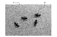
- It is a figure which shows an example of the preprocessed image which preprocessed with respect to the input image.
- FIG. 10 is a diagram showing an example of an initial polygon image in which initial polygons to be recognized are generated
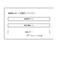
- FIG. 7 is a diagram showing an example of an operation screen for selecting an initial polygon generation mode
- FIG. 4 is a diagram showing an example of a segmented image in which regions are generated by performing superpixels
- FIG. 10 is a diagram showing an example of a segmented image obtained by performing super-pixel processing on a designated area;
- FIG. 10 is a diagram showing an example of a segment image in which a deletion area is specified among areas included in polygons to be recognized;
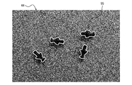
- FIG. 10 is a diagram showing an example of a corrected polygon image in which corrected polygons are generated by correcting initial polygons; It is a figure which compares an initial polygon and a correction polygon.
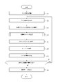
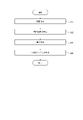
- 4 is a flow chart showing a procedure example of a teaching data generation method;
- FIG. 10 is a flow chart showing an example of a procedure for generating initial polygons by machine learning inference;
- FIG. 7 is a flow chart showing an example of a procedure for generating an initial polygon by foreground extraction using hue data;
- FIG. 10 is a flow chart showing an example of a procedure for generating initial polygons by graph cutting;
- FIG. 10 is a flow chart showing an example of a procedure for executing machine learning for generating initial polygons based on polygon correction data;
- FIG. FIG. 16 is a flow chart showing a procedure following
- the accuracy of assigning label information to an object different from the learned object may decrease.
- the robustness in assigning label information may decrease. According to the teacher data generation device and the teacher data generation device according to an embodiment of the present disclosure, robustness in assigning label information can be improved.
- a training data generation device 10 is a machine that performs segmentation on pixel-by-pixel image data including an image of a recognition target 50 (see FIG. 2 , etc.), which is image data having pixels. Create training data for generating learning models. A machine learning model that performs segmentation is also referred to as a first machine learning model.
- the training data generation device 10 generates information as training data in which polygons representing the outline of the recognition target 50 are associated with at least one input image 40 (see FIG. 2, etc.) including the recognition target 50 image.
- the training data generation device 10 may generate training data by executing the following procedure, for example.
- the training data generation device 10 executes a first process of generating polygon data along the outline of the portion of the input image 40 determined to be the image of the recognition target 50 .
- the training data generation device 10 generates an initial polygon 51 (see FIG. 4) as an initial value of polygon data.
- the training data generation device 10 also executes a second process of setting segments 52 (see FIG. 6 and the like) obtained by dividing the input image 40 into regions based on the luminance gradient.
- the training data generation device 10 may perform super-pixel processing as a second process to add segmentation information to the input image 40 . In other words, the training data generation device 10 sets the segments 52 for the input image 40 by performing superpixels.
- the training data generating device 10 modifies the polygon based on the segment 52 set in the image data to generate a modified polygon 55 (see FIG. 9).
- the corrected polygon 55 is also called corrected polygon data.
- the training data generation device 10 generates training data by adding label information for the input image 40 to the data for generating the modified polygon 55 as the polygon data in the input image 40 .
- the training data generation device 10 includes an input unit 12, a control unit 14, and an output unit 16.
- the input unit 12 receives input of the input image 40 .
- the control unit 14 acquires the input image 40 from the input unit 12 and generates teacher data based on the input image 40 .
- the output unit 16 outputs teacher data generated by the control unit 14 .
- the input unit 12 has an interface that receives input of the input image 40 .
- the output unit 16 has an interface for outputting teacher data.
- the interface may comprise a communication device configured to communicate wiredly or wirelessly.
- a communication device may be configured to be able to communicate with communication schemes based on various communication standards.
- a communication device may be configured according to known communication technologies.
- the input unit 12 may include an input device that receives input of information, data, etc. from the user.
- the input device may include, for example, a touch panel or touch sensor, or a pointing device such as a mouse.
- the input device may be configured including physical keys.
- the input device may include an audio input device such as a microphone.
- the control unit 14 may include at least one processor to provide control and processing power to perform various functions.
- the processor may execute programs that implement various functions of the controller 14 .
- a processor may be implemented as a single integrated circuit.
- An integrated circuit is also called an IC (Integrated Circuit).
- a processor may be implemented as a plurality of communicatively coupled integrated and discrete circuits. Processors may be implemented based on various other known technologies.
- the control unit 14 may include a storage unit.
- the storage unit may include an electromagnetic storage medium such as a magnetic disk, or may include a memory such as a semiconductor memory or a magnetic memory.
- the storage unit stores various information.
- the storage unit stores programs and the like executed by the control unit 14 .
- the storage unit may be configured as a non-transitory readable medium.
- the storage section may function as a work memory for the control section 14 . At least part of the storage unit may be configured separately from the control unit 14 .
- control unit 14 includes an image processing unit 141, an initial polygon generation unit 142, a superpixel unit 143, a polygon correction unit 144, a labeling unit 145, and a teacher data generation unit 146. It is assumed that each component of the control unit 14 is configured to be capable of executing processing necessary for generating teacher data.
- the control unit 14 may include a plurality of processors respectively corresponding to the plurality of components. Each processor is configured to be able to share and execute the processing of each component.
- the control unit 14 may be configured such that a single processor can execute necessary processing.
- the input unit 12 receives an input image 40 illustrated in FIG. 2 and outputs it to the control unit 14 .
- the input image 40 includes the image of the recognition target 50 and is used for generating teacher data.
- the input unit 12 may accept input of one image as the input image 40, or may accept input of two or more images.
- the image processing unit 141 of the control unit 14 performs image processing aimed at reducing noise included in the input image 40 acquired from the input unit 12 and enhancing the contour of the recognition target 50 .
- the image processing unit 141 may perform processing such as contrast correction, gamma correction, bilateral filtering, or Gaussian filtering, for example.
- the image processing unit 141 selects processing or adjusts processing parameters so that the outline of the recognition target 50 is emphasized according to the content of the acquired input image 40 or the purpose of the image processing.
- the processing executed by the image processing unit 141 is also called preprocessing.
- An image obtained by performing preprocessing on the input image 40 is also referred to as a preprocessed image 41 .
- a preprocessed image 41 is illustrated in FIG.
- the initial polygon generator 142 of the control unit 14 generates an initial polygon 51 for the preprocessed image 41, as illustrated in FIG.
- the initial polygon 51 is a line representing the contour of the recognition target 50 .
- the image in which the initial polygons 51 are generated is also called a polygon generated image 42 .
- the initial polygon generator 142 generates an initial polygon 51 for the input image 40 when preprocessing is not performed.
- the process of generating the initial polygon 51 is included in the first process.
- the initial polygon generation unit 142 may perform the processing described below in order to generate the initial polygon 51 .
- the initial polygon generating unit 142 uses a pre-trained machine learning model to execute inference of object detection by machine learning on the input image 40 or the preprocessed image 41 that has been input, and converts the output contour information into an initial polygon. It may be used as polygon 51.
- the machine learning model used for inference to generate the initial polygon 51 is also called a second machine learning model.
- the initial polygon generation unit 142 uses the initial polygon 51 obtained by machine learning inference as a cost function to generate a polygon generated image.
- Graph cut processing for 42 may also be performed.
- the initial polygon generator 142 may use the data obtained by the graph cutting process as the initial polygon 51 .
- the initial polygon generator 142 designates a region for the input image 40 or the preprocessed image 41, extracts the background color data of the designated region, and obtains the foreground contour using the hue value of the background color data. may be used as the initial polygon 51.
- the method of extracting the foreground in this manner is a general method known for chromakey synthesis and the like. If the background of the image has a simple structure, the outline can be extracted at high speed even if there are multiple objects in the foreground as the recognition target 50 .
- the initial polygon generator 142 may apply the graph cut processing to the cost function created by the user and use the obtained data as the initial polygon 51 .
- the training data generation device 10 may receive an input designated by the user as to which process the initial polygon generation section 142 is to perform.
- Input unit 12 may include a user interface.
- the input unit 12 may present a selection screen as shown in FIG. 5 to the user and receive an input from the user for selecting a process.
- Each mode illustrated in FIG. 5 may be associated with information specifying which of the processes described above is to be executed, or may be associated with parameters specified when executing each process described above.
- the initial polygon generation unit 142 may generate the initial polygon 51 by foreground extraction using hue data, graph cutting, inference by machine learning, or a combination of these methods.
- Foreground extraction using hue data can also be called background removal based on hue information.
- Inference by machine learning can also be called inference of detection of the recognition target 50 by the second machine learning model.
- the initial polygon generation unit 142 performs a predetermined algorithm including at least one of background removal based on hue information, graph cut, and inference of detection of the recognition target 50 by the second machine learning model. may be used to generate polygon data.
- the initial polygon generator 142 may specify at least a partial area of the input image 40 and generate the initial polygon 51 within that area.
- a region designated as a target for generating the initial polygon 51 is also called a first region.
- a super pixel is known as an image processing method that extracts a portion of the input image 40 with a high luminance gradient and divides the image into a plurality of regions along contour lines.
- the superpixel unit 143 of the control unit 14 performs superpixels on a designated region 53 including at least a portion of the input image 40 to divide it into segments 52, as illustrated in FIGS.
- the superpixel unit 143 associates segmentation information identifying the boundaries of the generated segments 52 with the image. Images with associated segmentation information are also referred to as segment images 43 . Execution of superpixels is included in the second processing.
- the superpixel unit 143 may appropriately set the specified area 53 (see FIG. 6) targeted for superpixels.
- the specified area 53 is also called a second area.
- the super-pixel unit 143 may set the designated area 53 so as to include all the initial polygons 51 based on the data of the initial polygons 51 .
- the superpixel unit 143 generates a segment 52 with a range including four recognition targets 50 as the specified region 53 .
- the superpixel unit 143 may set the designated area 53 so as to individually include each initial polygon 51 .
- the superpixel unit 143 generates a segment 52 by using a range that individually includes each recognition target 50 as the specified region 53 .
- the superpixel unit 143 may receive an input specifying a range from the user and set the specified area 53 based on the user's specification. When the super-pixel unit 143 automatically sets the specified area 53 , it may be possible to set how large the specified area 53 is to be relative to the area of the initial polygon 51 . The superpixel unit 143 can speed up superpixel processing and reduce the load of superpixel processing by limiting the processing range instead of the entire image.
- a polygon correction unit 144 of the control unit 14 adds a segment 52 to the initial polygon 51 or deletes a part of the segment 52 from the initial polygon 51 based on the initial polygon 51 .
- the polygon correction unit 144 corrects the initial polygon 51 or deletes the data of the initial polygon 51 to which the label is not attached based on the user's operation for the portion where the initial polygon 51 does not accurately capture the outline of the recognition target 50 . or For example, as shown in FIG. 8, when the initial polygon 51 includes the shadow of the recognition target 50 as the outline of the recognition target 50, the polygon correction unit 144 designates the segment 52 marked with an asterisk as the deletion target region 54. designated and deleted from the initial polygon 51.
- the polygon correction unit 144 can generate a corrected polygon 55 that accurately captures the contour of the recognition target 50 as shown in FIG.
- the image associated with the information of the modified polygon 55 is also called the polygon modified image 44 .
- the polygon correction unit 144 may add the asterisked segment 52 as the initial polygon 51 to generate the modified polygon 55 .
- the polygon correction unit 144 can generate a corrected polygon 55 representing a contour close to the true contour of the recognition target 50 by removing the deletion target region 54 from the range surrounded by the initial polygon 51 .
- the polygon correction unit 144 may correct the initial polygon 51 based on the segmentation information generated by the superpixel unit 143, in addition to correcting the initial polygon 51 based on the designation of arbitrary pixels or regions by the user. For example, when an arbitrary pixel value is specified by the user, the polygon correction unit 144 can generate a corrected polygon 55 by correcting the segment 52 including the specified pixel value as the foreground or background.
- the initial polygon 51 can be sped up. For example, in FIG. 10, by designating the deletion target area 54 in the range surrounded by the initial polygon 51 as the background, the portion corresponding to the shadow of the recognition target 50 can be corrected with less operation.
- the polygon correction unit 144 may automatically correct the initial polygon 51.
- the labeling unit 145 of the control unit 14 gives the input image 40 or the preprocessed image 41 label information describing the recognition target 50 whose outline is represented by the initial polygon 51 or the modified polygon 55 .
- the labeling unit 145 gives label information to the initial polygon 51 or the modified polygon 55.
- the label assigning unit 145 may receive an input of label information from the user and assign label information specified by the user.
- the label assigning unit 145 may assign label information determined by inference based on machine learning.
- the label assigning unit 145 may assign the label information at any timing during the period from the acquisition of the input image 40 from the input unit 12 to the generation of the corrected polygon 55 by the polygon correcting unit 144 .
- the teacher data generation unit 146 of the control unit 14 generates data that associates the input image 40, the data of the correction polygon 55, and the label information as teacher data, and outputs the data to the output unit 16.
- control unit 14 When the control unit 14 acquires a plurality of input images 40 from the input unit 12, it executes each of the above-described processes for each input image 40 to generate teacher data.
- the output unit 16 outputs the teacher data acquired from the control unit 14 to an external device.
- the training data generation device 10 can generate training data by generating and correcting the initial polygons 51 .
- the controller 14 of the training data generation device 10 may execute the training data generation method including the procedure of the flowchart illustrated in FIG. 11 .
- the teacher data generation method may be implemented as a teacher data generation program that is executed by a processor that constitutes the controller 14 of the teacher data generation device 10 .
- the teacher data generation program may be stored in a non-transitory computer-readable medium.
- the control unit 14 of the training data generation device 10 acquires the input image 40 via the input unit 12 (step S1).
- the control unit 14 performs preprocessing on the input image 40 (step S2).
- the control unit 14 selects a generation mode for the initial polygon 51 (step S3).
- the control unit 14 selects one of modes of inference by machine learning, foreground extraction using hue data, and graph cut.
- the control unit 14 generates an initial polygon 51 (step S4).
- the control unit 14 generates the initial polygon 51 in the mode selected in the procedure of step S3.
- the control unit 14 executes the procedure of the flow chart shown in FIG. 12 in order to generate the initial polygon 51 in the machine learning inference mode.
- the control unit 14 acquires a machine learning model (step S11).
- the control unit 14 performs inference to detect the contour of the recognition target 50 from the input image 40 using the machine learning model (step S12).
- the control unit 14 determines whether to execute graph cutting (step S13). If the control unit 14 does not determine to execute the graph cut (step S13: NO), the process proceeds to step S15. When determining to execute the graph cut (step S13: YES), the control unit 14 executes the graph cut on the input image 40 using the contour detected by executing the inference as the cost function (step S14).
- the control unit 14 generates an initial polygon 51 based on the contour of the recognition target 50 detected by executing the inference (step S15). After executing the procedure of step S15, the control unit 14 ends the execution of the flowchart of FIG. 12 and proceeds to the procedure of step S5 of FIG.
- the control unit 14 executes the procedure of the flowchart shown in FIG. 13 in order to generate the initial polygon 51 in the foreground extraction mode using hue data.
- the control unit 14 designates the range from which the foreground is to be extracted (step S21).
- the control unit 14 acquires the background color in the specified range as the peripheral hue (step S22).
- the control unit 14 removes the background (step S23).
- the control unit 14 generates the initial polygon 51 based on the outline of the foreground extracted by removing the background (step S24). After executing the procedure of step S24, the control unit 14 ends the execution of the flowchart of FIG. 13 and proceeds to the procedure of step S5 of FIG.
- the control unit 14 executes the procedure of the flowchart shown in FIG. 14 in order to generate the initial polygon 51 in graph cut mode.
- the control unit 14 generates a mask (step S31).
- the control unit 14 executes graph cutting based on the mask (step S32).
- the control unit 14 determines whether or not the graph cut has ended (step S33). If the graph cut has not ended (step S33: NO), the control unit 14 returns to the procedure of step S31.
- the control unit 14 When the graph cut is finished (step S33: YES), the control unit 14 generates the initial polygon 51 based on the extraction result of the recognition target 50 by the graph cut (step S34). After executing the procedure of step S34, the control unit 14 ends the execution of the flowchart of FIG. 14 and proceeds to the procedure of step S5 of FIG.
- the control unit 14 executes superpixel (step S5).
- the control unit 14 modifies the polygon based on the segmentation information specifying the segments 52 generated by the superpixels (step S6).
- the control unit 14 gives label information (step S7).
- the control unit 14 determines whether there is another input image 40 for generating teacher data, that is, whether there is next image data (step S8).
- step S8: YES the control unit 14 returns to the procedure of step S2 and processes the next input image 40.
- FIG. When the next input image 40 does not exist (step S8: NO), the control unit 14 associates the data of the polygon generated in the input image 40 with the label information given to the polygon to the input image 40, and creates teacher data. Generate (step S9). After executing the procedure of step S9, the control unit 14 ends the execution of the procedure of the flowchart of FIG.
- the control unit 14 may execute the label information addition procedure in step S7 at any timing from after step S1 to after step S6.
- the control unit 14 gives the label information to the input image 40 when giving the label information before generating the initial polygon 51 .
- the control unit 14 assigns the label information assigned to the input image 40 to the generated initial polygon 51 .
- the control unit 14 may extract the recognition target 50 that matches the label information given to the input image 40 and generate the initial polygon 51 for the extracted recognition target 50 .
- the control unit 14 may execute the procedure for generating the initial polygons 51 in step S4 of FIG. 11 after the procedure for executing superpixels in step S5. In this case, the control unit 14 can generate the initial polygon 51 based on the segmentation information.
- the control unit 14 may perform superpixeling on the entire image again when correcting polygons. For example, if the control unit 14 performs super-pixels only on a partial range of the input image 40 in the procedure of step S5, no segmentation information is associated outside the super-pixels range. Therefore, it can be envisioned in various embodiments that control unit 14 performs superpixeling again on the entire image when modifying polygons.
- the initial polygon 51 is modified based on segmentation information specifying segments 52 set by performing superpixels on the input image 40 or preprocessed image 41 that has been input. By doing so, the initial polygon 51 is corrected with high accuracy so that the contour represented by the corrected polygon 55 approaches the true contour of the recognition target 50 . Also, the time required to correct the initial polygon 51 is shortened.
- teacher data generation device 10 and the teacher data generation method according to the present embodiment polygons can be generated with high accuracy. As a result, robustness against non-identical objects may be improved.
- a configuration can be considered in which training data is generated by detecting the contour of the foreground from an arbitrary background with high accuracy.
- this configuration if one image contains images of a plurality of objects, the work of inputting the shape of the foreground region increases.
- the input of the shape of the foreground region can be omitted by generating the initial polygon 51 . As a result, the user's workload and working time can be reduced.
- a configuration that uses a machine learning model to label the segmentation of each pixel in an image can be considered.
- work time and work cost for preparing initial teacher data as well as computational load and computational cost for executing learning for generating a machine learning model are incurred.
- the teacher data generation device 10 and the teacher data generation method according to the present embodiment by generating the initial polygon 51 and correcting it, polygons can be generated with high accuracy without user's work. As a result, the user's workload and working time can be reduced.
- the teacher data generation device 10 may sequentially generate teacher data for each of the plurality of input images 40 .
- the teacher data generation device 10 may feed back correction data of the initial polygon 51 in the input image 40 processed in the earliest order to generate the initial polygon 51 in the input image 40 processed in the latter order.
- the accuracy of the initial polygon 51 is enhanced.
- the workload or computational load of modifying the initial polygon 51 can be reduced.
- the training data generation device 10 generates a corrected polygon 55 by deleting the shadow portion from the initial polygon 51 in the polygon correction section 144 of the control section 14 .
- the control unit 14 characterizes the image of the deleted shadow portion as corrected data, and feeds back the data characterizing the corrected data to the generation of the initial polygon 51 in the input image 40 to be processed later.
- the control unit 14 can detect the shadow portion from the input image 40 based on the data characterizing the image of the shadow portion as correction data, and remove the shadow portion from the beginning when generating the initial polygon 51 .
- the data characterizing the modified data including the image of the modified portion such as the shadow portion includes, for example, pixel value information, texture information, or shape information of the image.
- Data characterizing the modified data of the initial polygon 51 is also referred to as characterization data. Characterization data can also be used as a condition for selecting the type of image processing or determining parameters for image processing in the image processing unit 141 of the control unit 14 . That is, the image processing unit 141 may modify the parameters applied to the preprocessing for the input image 40 to be processed later, based on the modified data of the polygon data. Parameters that apply to preprocessing are also referred to as preprocessing parameter values.
- the control unit 14 may process a plurality of input images 40 including images of the same type of object.
- the machine learning model used for inference is an overrun of the input image 40.
- a trained machine learning model can be used. For example, when the control unit 14 satisfies a predetermined condition when starting to process the next input image 40, the control unit 14 generates the initial polygon 51 by learning using teacher data generated based on the input image 40 that has already been processed. You may generate and transfer a machine learning model to be used for
- the control unit 14 Based on the difference between the initial polygon 51 (polygon data) and the corrected polygon 55 (corrected polygon data) in the previously executed processing of the input image 40, the control unit 14 inputs as preprocessing of the next input image 40 to be processed. Image 40 may be corrected. Further, the control unit 14 controls the input image 40 to be processed next based on the correction data from the initial polygon 51 (polygon data) to the corrected polygon 55 (corrected polygon data) in the processing of the input image 40 previously executed. The input image 40 may be corrected as processing.
- the control unit 14 may feed back the correction data of the initial polygon 51 as described above by executing the teaching data generation method including the procedures of the flow charts illustrated in FIGS. 15 and 16 .
- the control unit 14 acquires the input image 40 via the input unit 12 (step S51).
- the control unit 14 performs preprocessing on the input image 40 (step S52).
- the control unit 14 selects a generation mode for the initial polygon 51 (step S53).
- the control unit 14 generates the initial polygon 51 (step S54).
- the control unit 14 generates the initial polygon 51 in the mode selected in the procedure of step S53.
- the control unit 14 may execute the procedure shown in any one of FIGS. 12, 13, and 14 in the procedure of step S54.
- Each procedure from steps S51 to S54 in FIG. 15 corresponds to each procedure from steps S1 to S4 in FIG.
- the control unit 14 automatically corrects the initial polygon 51 (step S55). Specifically, the control unit 14 may correct the initial polygon 51 based on correction data for the initial polygon 51 when the input image 40 was processed prior to the input image 40 currently being processed. The control unit 14 does not have to execute the procedure of step S55.
- the control unit 14 executes superpixel (step S56).
- the control unit 14 modifies the polygon based on the segmentation information specifying the segments 52 generated by the superpixels (step S57).
- the control unit 14 gives label information (step S58).
- the control unit 14 determines whether there is another input image 40 for generating teacher data, that is, whether there is next image data (step S59). If the next input image 40 does not exist (step S59: NO), the control unit 14 associates the data of the polygon generated in the input image 40 with the label information given to the polygon for the input image 40, and creates teacher data.
- Generate step S60. After executing the procedure of step S60, the control unit 14 ends the execution of the procedure of the flowchart of FIG.
- Each procedure from steps S56 to S60 in FIG. 15 corresponds to each procedure from steps S5 to S9 in FIG.
- step S61 determines whether or not the polygon has been corrected in the processing of the previous input image 40 (step S61). If there is no polygon correction in the processing of the previous input image 40 (step S61: NO), the control unit 14 returns to step S52 to process the next input image 40.
- step S62 If the polygon has been modified in the processing of the previous input image 40 (step S61: YES), the control unit 14 characterizes the modified data (step S62). The control unit 14 learns correction data (step S63). The control unit 14 may generate a machine learning model that is used to generate the initial polygon 51 by learning correction data. After executing the procedure of step S ⁇ b>63 , the control unit 14 returns to the procedure of step S ⁇ b>52 to process the next input image 40 .
- the training data generation device 10 can improve the accuracy of the initial polygon 51 by feeding back the characterization data. Further, the training data generation device 10 can further improve the accuracy of the initial polygon 51 by automatically correcting the initial polygon 51 based on the characterization data. Further, the training data generation device 10 can enhance the outline of the recognition target 50 and make it easier to detect the initial polygon 51 by adjusting the parameters in the preprocessing of the input image 40 based on the characterized data. As a result, the accuracy of the initial polygon 51 is further improved.
- a storage medium on which the program is recorded for example, an optical disk, an optical Magnetic disk, CD-ROM, CD-R, CD-RW, magnetic tape, hard disk, memory card, etc.
- the implementation form of the program is not limited to an application program such as an object code compiled by a compiler or a program code executed by an interpreter. good.
- the program may or may not be configured so that all processing is performed only in the CPU on the control board.
- the program may be configured to be partially or wholly executed by another processing unit mounted on an expansion board or expansion unit added to the board as required.
- Embodiments according to the present disclosure are not limited to any specific configuration of the embodiments described above. Embodiments of the present disclosure extend to any novel feature or combination thereof described in the present disclosure or any novel method or process step or combination thereof described. be able to.
- Descriptions such as “first” and “second” in this disclosure are identifiers for distinguishing the configurations. Configurations that are differentiated in descriptions such as “first” and “second” in this disclosure may interchange the numbers in that configuration. For example, a first process can exchange identifiers “first” and “second” with a second process. The exchange of identifiers is done simultaneously. The configurations are still distinct after the exchange of identifiers. Identifiers may be deleted. Configurations from which identifiers have been deleted are distinguished by codes. The description of identifiers such as “first” and “second” in this disclosure should not be used as a basis for interpreting the order of the configuration or the existence of lower numbered identifiers.
- the configuration according to the present disclosure includes an input unit 12 that acquires at least one input image 40 that includes an image of the recognition target 50, and a first region of the input image 40 along the contour of a portion that is determined to be the image of the recognition target 50. a first process of generating polygon data, a second process of setting segments 52 obtained by dividing the input image 40 into areas based on the luminance gradient, and a correction of the polygon data based on the segments 52 set by the second process. It may be implemented as an image processing apparatus including a control unit 14 for generating modified polygon data.
- Teacher data generation device (12: input unit, 14: control unit, 16: output unit, 141: image processing unit, 142: initial polygon generation unit, 143: super pixel unit, 144: polygon correction unit, 145: label assignment part, 146: teacher data generation part) 40 Input image 41 Preprocessed image 42 Polygon generated image 43 Segment image 44 Polygon corrected image 50 Recognition object 51 Initial polygon 52 Segment 53 Designated area 54 Deleted area 55 Corrected polygon
Landscapes
- Engineering & Computer Science (AREA)
- Theoretical Computer Science (AREA)
- Physics & Mathematics (AREA)
- General Physics & Mathematics (AREA)
- Computer Vision & Pattern Recognition (AREA)
- Multimedia (AREA)
- Software Systems (AREA)
- Computational Linguistics (AREA)
- Medical Informatics (AREA)
- Artificial Intelligence (AREA)
- Computing Systems (AREA)
- Evolutionary Computation (AREA)
- General Health & Medical Sciences (AREA)
- Health & Medical Sciences (AREA)
- Databases & Information Systems (AREA)
- Data Mining & Analysis (AREA)
- General Engineering & Computer Science (AREA)
- Mathematical Physics (AREA)
- Image Analysis (AREA)
Priority Applications (5)
| Application Number | Priority Date | Filing Date | Title |
|---|---|---|---|
| CN202280037072.6A CN117377985A (zh) | 2021-05-24 | 2022-05-20 | 教导数据生成设备、教导数据生成方法及图像处理设备 |
| US18/563,739 US20240221197A1 (en) | 2021-05-24 | 2022-05-20 | Teaching data generation device, teaching data generation method, and image processing device |
| EP22811267.8A EP4350610A4 (en) | 2021-05-24 | 2022-05-20 | Teaching data generation device, teaching data generation method, and image processing device |
| JP2023523453A JP7467773B2 (ja) | 2021-05-24 | 2022-05-20 | 教師データ生成装置、教師データ生成方法、及び画像処理装置 |
| JP2024060418A JP2024088718A (ja) | 2021-05-24 | 2024-04-03 | 教師データ生成装置、教師データ生成方法、及び画像処理装置 |
Applications Claiming Priority (2)
| Application Number | Priority Date | Filing Date | Title |
|---|---|---|---|
| JP2021-087206 | 2021-05-24 | ||
| JP2021087206 | 2021-05-24 |
Publications (1)
| Publication Number | Publication Date |
|---|---|
| WO2022249997A1 true WO2022249997A1 (ja) | 2022-12-01 |
Family
ID=84229873
Family Applications (1)
| Application Number | Title | Priority Date | Filing Date |
|---|---|---|---|
| PCT/JP2022/021023 Ceased WO2022249997A1 (ja) | 2021-05-24 | 2022-05-20 | 教師データ生成装置、教師データ生成方法、及び画像処理装置 |
Country Status (5)
| Country | Link |
|---|---|
| US (1) | US20240221197A1 (https=) |
| EP (1) | EP4350610A4 (https=) |
| JP (2) | JP7467773B2 (https=) |
| CN (1) | CN117377985A (https=) |
| WO (1) | WO2022249997A1 (https=) |
Families Citing this family (2)
| Publication number | Priority date | Publication date | Assignee | Title |
|---|---|---|---|---|
| US12333828B2 (en) * | 2021-08-04 | 2025-06-17 | Motional Ad Llc | Scalable and realistic camera blockage dataset generation |
| US12548311B2 (en) | 2021-08-04 | 2026-02-10 | Motional Ad Llc | Training a neural network using a data set with labels of multiple granularities |
Citations (7)
| Publication number | Priority date | Publication date | Assignee | Title |
|---|---|---|---|---|
| JP2012085233A (ja) * | 2010-10-14 | 2012-04-26 | Sharp Corp | 映像処理装置、映像処理方法、及びプログラム |
| JP2017220098A (ja) * | 2016-06-09 | 2017-12-14 | 日本電信電話株式会社 | 画像処理装置、画像処理方法、画像処理プログラム及び画像認識システム |
| JP2018510320A (ja) * | 2014-12-09 | 2018-04-12 | ビーエーエスエフ ソシエタス・ヨーロピアBasf Se | 光学検出器 |
| JP2019061658A (ja) * | 2017-08-02 | 2019-04-18 | 株式会社Preferred Networks | 領域判別器訓練方法、領域判別装置、領域判別器訓練装置及びプログラム |
| JP2019101535A (ja) | 2017-11-29 | 2019-06-24 | コニカミノルタ株式会社 | 教師データ作成装置および該方法ならびに画像セグメンテーション装置および該方法 |
| CN111489357A (zh) * | 2019-01-29 | 2020-08-04 | 广州市百果园信息技术有限公司 | 一种图像分割方法、装置、设备及存储介质 |
| WO2020174862A1 (ja) * | 2019-02-28 | 2020-09-03 | ソニー株式会社 | 情報処理装置、情報処理方法および情報処理システム |
Family Cites Families (9)
| Publication number | Priority date | Publication date | Assignee | Title |
|---|---|---|---|---|
| US6246782B1 (en) * | 1997-06-06 | 2001-06-12 | Lockheed Martin Corporation | System for automated detection of cancerous masses in mammograms |
| JP6330385B2 (ja) * | 2014-03-13 | 2018-05-30 | オムロン株式会社 | 画像処理装置、画像処理方法およびプログラム |
| US9972092B2 (en) * | 2016-03-31 | 2018-05-15 | Adobe Systems Incorporated | Utilizing deep learning for boundary-aware image segmentation |
| US20180260759A1 (en) * | 2017-03-07 | 2018-09-13 | Mighty AI, Inc. | Segmentation of Images |
| CN106952278A (zh) * | 2017-04-05 | 2017-07-14 | 深圳市唯特视科技有限公司 | 一种基于超像素的动态户外环境中的自动分割方法 |
| GB201709672D0 (en) * | 2017-06-16 | 2017-08-02 | Ucl Business Plc | A system and computer-implemented method for segmenting an image |
| JP7059883B2 (ja) * | 2018-10-05 | 2022-04-26 | オムロン株式会社 | 学習装置、画像生成装置、学習方法、及び学習プログラム |
| JP2020091640A (ja) * | 2018-12-05 | 2020-06-11 | 国立大学法人京都大学 | 物体分類システム、学習システム、学習データ生成方法、学習済モデル生成方法、学習済モデル、判別装置、判別方法、およびコンピュータプログラム |
| JP2020135141A (ja) * | 2019-02-14 | 2020-08-31 | 株式会社Preferred Networks | 訓練装置、訓練方法及び予測装置 |
-
2022
- 2022-05-20 CN CN202280037072.6A patent/CN117377985A/zh active Pending
- 2022-05-20 JP JP2023523453A patent/JP7467773B2/ja active Active
- 2022-05-20 US US18/563,739 patent/US20240221197A1/en active Pending
- 2022-05-20 WO PCT/JP2022/021023 patent/WO2022249997A1/ja not_active Ceased
- 2022-05-20 EP EP22811267.8A patent/EP4350610A4/en active Pending
-
2024
- 2024-04-03 JP JP2024060418A patent/JP2024088718A/ja active Pending
Patent Citations (7)
| Publication number | Priority date | Publication date | Assignee | Title |
|---|---|---|---|---|
| JP2012085233A (ja) * | 2010-10-14 | 2012-04-26 | Sharp Corp | 映像処理装置、映像処理方法、及びプログラム |
| JP2018510320A (ja) * | 2014-12-09 | 2018-04-12 | ビーエーエスエフ ソシエタス・ヨーロピアBasf Se | 光学検出器 |
| JP2017220098A (ja) * | 2016-06-09 | 2017-12-14 | 日本電信電話株式会社 | 画像処理装置、画像処理方法、画像処理プログラム及び画像認識システム |
| JP2019061658A (ja) * | 2017-08-02 | 2019-04-18 | 株式会社Preferred Networks | 領域判別器訓練方法、領域判別装置、領域判別器訓練装置及びプログラム |
| JP2019101535A (ja) | 2017-11-29 | 2019-06-24 | コニカミノルタ株式会社 | 教師データ作成装置および該方法ならびに画像セグメンテーション装置および該方法 |
| CN111489357A (zh) * | 2019-01-29 | 2020-08-04 | 广州市百果园信息技术有限公司 | 一种图像分割方法、装置、设备及存储介质 |
| WO2020174862A1 (ja) * | 2019-02-28 | 2020-09-03 | ソニー株式会社 | 情報処理装置、情報処理方法および情報処理システム |
Non-Patent Citations (1)
| Title |
|---|
| See also references of EP4350610A4 |
Also Published As
| Publication number | Publication date |
|---|---|
| CN117377985A (zh) | 2024-01-09 |
| US20240221197A1 (en) | 2024-07-04 |
| EP4350610A1 (en) | 2024-04-10 |
| JP2024088718A (ja) | 2024-07-02 |
| JPWO2022249997A1 (https=) | 2022-12-01 |
| JP7467773B2 (ja) | 2024-04-15 |
| EP4350610A4 (en) | 2025-04-23 |
Similar Documents
| Publication | Publication Date | Title |
|---|---|---|
| JP7303844B2 (ja) | データ拡張システム、データ拡張方法、及びプログラム | |
| US20220301239A1 (en) | Automatic coloring of line drawing | |
| JP2024088718A (ja) | 教師データ生成装置、教師データ生成方法、及び画像処理装置 | |
| US12125274B2 (en) | Identification information assignment apparatus, identification information assignment method, and program | |
| WO2019011342A1 (zh) | 布料识别的方法、设备、电子设备及储存介质 | |
| US9571697B2 (en) | Image processing device setting sharpness adjustment degrees for object regions and performing unsharp masking process | |
| JP7173309B2 (ja) | 学習方法、学習プログラム、および、学習装置 | |
| JP7453668B2 (ja) | 学習処理装置および学習処理方法、物体検出装置および物体検出方法、ならびに、プログラム | |
| JP2025014039A (ja) | 認識モデル生成方法及び認識モデル生成装置 | |
| JP2020135653A (ja) | 映像補正装置及びそのプログラム | |
| JP2020140659A (ja) | 情報処理装置、情報処理方法及びプログラム | |
| KR20220124593A (ko) | 의상제거 이미지에 기초한 의상 변형 방법 | |
| JP6900016B2 (ja) | 画像領域抽出処理方法及び画像領域抽出処理プログラム | |
| JP7045103B1 (ja) | データ拡張装置、データ拡張システム、及びデータ拡張プログラム | |
| JP2022147713A (ja) | 画像生成装置、学習装置、及び、画像生成方法 | |
| CN121187176A (zh) | 机器人绘画方法、装置、设备及存储介质 | |
| JP2017033556A (ja) | 画像処理方法及び電子機器 | |
| JP2022156631A (ja) | 画像補正モデル生成方法、画像補正モデル生成プログラム及び画像補正モデル生成装置 | |
| US12051135B2 (en) | System and method for a precise semantic segmentation | |
| JP7631042B2 (ja) | 学習データ生成システム | |
| JP2005217984A (ja) | 画像処理装置 | |
| US20220036040A1 (en) | Biometric recognition apparatus and biometric recognition method | |
| JP2023048873A (ja) | 情報処理装置、情報処理方法及びプログラム | |
| KR102668050B1 (ko) | 그림 이미지를 추출하는 방법, 장치 및 컴퓨터 프로그램 | |
| KR102736798B1 (ko) | 인공지능을 이용한 편집된 이미지 검출 방법 및 시스템 |
Legal Events
| Date | Code | Title | Description |
|---|---|---|---|
| 121 | Ep: the epo has been informed by wipo that ep was designated in this application |
Ref document number: 22811267 Country of ref document: EP Kind code of ref document: A1 |
|
| WWE | Wipo information: entry into national phase |
Ref document number: 202280037072.6 Country of ref document: CN Ref document number: 18563739 Country of ref document: US Ref document number: 2023523453 Country of ref document: JP |
|
| NENP | Non-entry into the national phase |
Ref country code: DE |
|
| WWE | Wipo information: entry into national phase |
Ref document number: 2022811267 Country of ref document: EP |
|
| ENP | Entry into the national phase |
Ref document number: 2022811267 Country of ref document: EP Effective date: 20240102 |
|
| WWW | Wipo information: withdrawn in national office |
Ref document number: 2022811267 Country of ref document: EP |