WO2022249997A1 - Teaching data generation device, teaching data generation method, and image processing device - Google Patents
Teaching data generation device, teaching data generation method, and image processing device Download PDFInfo
- Publication number
- WO2022249997A1 WO2022249997A1 PCT/JP2022/021023 JP2022021023W WO2022249997A1 WO 2022249997 A1 WO2022249997 A1 WO 2022249997A1 JP 2022021023 W JP2022021023 W JP 2022021023W WO 2022249997 A1 WO2022249997 A1 WO 2022249997A1
- Authority
- WO
- WIPO (PCT)
- Prior art keywords
- input image
- polygon
- control unit
- data
- image
- Prior art date
Links
- 238000012545 processing Methods 0.000 title claims abstract description 56
- 238000000034 method Methods 0.000 title claims description 106
- 238000012549 training Methods 0.000 claims description 47
- 238000012937 correction Methods 0.000 claims description 31
- 238000010801 machine learning Methods 0.000 claims description 31
- 238000007781 pre-processing Methods 0.000 claims description 12
- 230000006870 function Effects 0.000 claims description 8
- 238000001514 detection method Methods 0.000 claims description 5
- 230000011218 segmentation Effects 0.000 description 13
- 238000000605 extraction Methods 0.000 description 10
- 238000010586 diagram Methods 0.000 description 8
- 238000004891 communication Methods 0.000 description 6
- 238000005520 cutting process Methods 0.000 description 5
- 238000012217 deletion Methods 0.000 description 5
- 230000037430 deletion Effects 0.000 description 5
- 238000012512 characterization method Methods 0.000 description 4
- 230000000052 comparative effect Effects 0.000 description 4
- 238000002372 labelling Methods 0.000 description 4
- 239000000284 extract Substances 0.000 description 3
- 238000005516 engineering process Methods 0.000 description 2
- 238000001914 filtration Methods 0.000 description 2
- 238000012986 modification Methods 0.000 description 2
- 230000004048 modification Effects 0.000 description 2
- 230000003287 optical effect Effects 0.000 description 2
- 230000002093 peripheral effect Effects 0.000 description 2
- 230000004075 alteration Effects 0.000 description 1
- 238000013459 approach Methods 0.000 description 1
- 230000002146 bilateral effect Effects 0.000 description 1
- 230000015572 biosynthetic process Effects 0.000 description 1
- 238000013135 deep learning Methods 0.000 description 1
- 230000002708 enhancing effect Effects 0.000 description 1
- 238000007429 general method Methods 0.000 description 1
- 238000003709 image segmentation Methods 0.000 description 1
- 238000003672 processing method Methods 0.000 description 1
- 239000004065 semiconductor Substances 0.000 description 1
- 238000003786 synthesis reaction Methods 0.000 description 1
- 238000012546 transfer Methods 0.000 description 1
Images


Classifications
-
- G—PHYSICS
- G06—COMPUTING; CALCULATING OR COUNTING
- G06N—COMPUTING ARRANGEMENTS BASED ON SPECIFIC COMPUTATIONAL MODELS
- G06N20/00—Machine learning
-
- G—PHYSICS
- G06—COMPUTING; CALCULATING OR COUNTING
- G06T—IMAGE DATA PROCESSING OR GENERATION, IN GENERAL
- G06T7/00—Image analysis
-
- G—PHYSICS
- G06—COMPUTING; CALCULATING OR COUNTING
- G06T—IMAGE DATA PROCESSING OR GENERATION, IN GENERAL
- G06T7/00—Image analysis
- G06T7/10—Segmentation; Edge detection
- G06T7/11—Region-based segmentation
-
- G—PHYSICS
- G06—COMPUTING; CALCULATING OR COUNTING
- G06V—IMAGE OR VIDEO RECOGNITION OR UNDERSTANDING
- G06V10/00—Arrangements for image or video recognition or understanding
- G06V10/70—Arrangements for image or video recognition or understanding using pattern recognition or machine learning
- G06V10/77—Processing image or video features in feature spaces; using data integration or data reduction, e.g. principal component analysis [PCA] or independent component analysis [ICA] or self-organising maps [SOM]; Blind source separation
- G06V10/774—Generating sets of training patterns; Bootstrap methods, e.g. bagging or boosting
Definitions
- the present disclosure relates to a training data generation device, a training data generation method, and an image processing device.
- Patent Document 1 a device that creates teacher data including labels attached to images based on the results of image segmentation using a machine learning model.
- a training data generation device includes an input unit, a control unit, and an output unit.
- the input unit acquires at least one input image including an image to be recognized.
- the control unit executes a first process of generating polygon data along the contour of the portion determined to be the image to be recognized from the first area of the input image.
- the control unit executes a second process of setting segments obtained by dividing the input image based on the luminance gradient.
- the control unit generates corrected polygon data by correcting the polygon data based on the segments set in the second processing.
- the control unit assigns label information to the input image to generate teacher data.
- the output unit outputs the teacher data.
- a training data generation method includes obtaining at least one input image including an image to be recognized.
- the training data generation method includes executing a first process of generating polygon data along a contour of a portion determined to be the image to be recognized from the first region of the input image.
- the training data generation method includes executing a second process of setting segments obtained by dividing the input image based on luminance gradients.
- the training data generating method includes generating corrected polygon data by correcting the polygon data based on the segments set in the second process.
- the training data generation method includes adding label information to the input image.
- the training data generation method includes generating and outputting training data.
- An image processing device includes an input unit and a control unit.
- the input unit acquires at least one input image including an image to be recognized.
- the control unit executes a first process of generating polygon data along the contour of the portion determined to be the image to be recognized from the first area of the input image.
- the control unit executes a second process of setting segments obtained by dividing the input image based on the luminance gradient.
- the control unit generates corrected polygon data by correcting the polygon data based on the segments set in the second processing.
- FIG. 1 is a block diagram showing a configuration example of a training data generation device according to an embodiment
- FIG. FIG. 4 is a diagram showing an example of an input image including a recognition target
- It is a figure which shows an example of the preprocessed image which preprocessed with respect to the input image.
- FIG. 10 is a diagram showing an example of an initial polygon image in which initial polygons to be recognized are generated
- FIG. 7 is a diagram showing an example of an operation screen for selecting an initial polygon generation mode
- FIG. 4 is a diagram showing an example of a segmented image in which regions are generated by performing superpixels
- FIG. 10 is a diagram showing an example of a segmented image obtained by performing super-pixel processing on a designated area;
- FIG. 10 is a diagram showing an example of a segment image in which a deletion area is specified among areas included in polygons to be recognized;
- FIG. 10 is a diagram showing an example of a corrected polygon image in which corrected polygons are generated by correcting initial polygons; It is a figure which compares an initial polygon and a correction polygon.
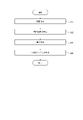
- 4 is a flow chart showing a procedure example of a teaching data generation method;
- FIG. 10 is a flow chart showing an example of a procedure for generating initial polygons by machine learning inference;
- FIG. 7 is a flow chart showing an example of a procedure for generating an initial polygon by foreground extraction using hue data;
- FIG. 10 is a flow chart showing an example of a procedure for generating initial polygons by graph cutting;
- FIG. 10 is a flow chart showing an example of a procedure for executing machine learning for generating initial polygons based on polygon correction data;
- FIG. FIG. 16 is a flow chart showing a procedure following
- the accuracy of assigning label information to an object different from the learned object may decrease.
- the robustness in assigning label information may decrease. According to the teacher data generation device and the teacher data generation device according to an embodiment of the present disclosure, robustness in assigning label information can be improved.
- a training data generation device 10 is a machine that performs segmentation on pixel-by-pixel image data including an image of a recognition target 50 (see FIG. 2 , etc.), which is image data having pixels. Create training data for generating learning models. A machine learning model that performs segmentation is also referred to as a first machine learning model.
- the training data generation device 10 generates information as training data in which polygons representing the outline of the recognition target 50 are associated with at least one input image 40 (see FIG. 2, etc.) including the recognition target 50 image.
- the training data generation device 10 may generate training data by executing the following procedure, for example.
- the training data generation device 10 executes a first process of generating polygon data along the outline of the portion of the input image 40 determined to be the image of the recognition target 50 .
- the training data generation device 10 generates an initial polygon 51 (see FIG. 4) as an initial value of polygon data.
- the training data generation device 10 also executes a second process of setting segments 52 (see FIG. 6 and the like) obtained by dividing the input image 40 into regions based on the luminance gradient.
- the training data generation device 10 may perform super-pixel processing as a second process to add segmentation information to the input image 40 . In other words, the training data generation device 10 sets the segments 52 for the input image 40 by performing superpixels.
- the training data generating device 10 modifies the polygon based on the segment 52 set in the image data to generate a modified polygon 55 (see FIG. 9).
- the corrected polygon 55 is also called corrected polygon data.
- the training data generation device 10 generates training data by adding label information for the input image 40 to the data for generating the modified polygon 55 as the polygon data in the input image 40 .
- the training data generation device 10 includes an input unit 12, a control unit 14, and an output unit 16.
- the input unit 12 receives input of the input image 40 .
- the control unit 14 acquires the input image 40 from the input unit 12 and generates teacher data based on the input image 40 .
- the output unit 16 outputs teacher data generated by the control unit 14 .
- the input unit 12 has an interface that receives input of the input image 40 .
- the output unit 16 has an interface for outputting teacher data.
- the interface may comprise a communication device configured to communicate wiredly or wirelessly.
- a communication device may be configured to be able to communicate with communication schemes based on various communication standards.
- a communication device may be configured according to known communication technologies.
- the input unit 12 may include an input device that receives input of information, data, etc. from the user.
- the input device may include, for example, a touch panel or touch sensor, or a pointing device such as a mouse.
- the input device may be configured including physical keys.
- the input device may include an audio input device such as a microphone.
- the control unit 14 may include at least one processor to provide control and processing power to perform various functions.
- the processor may execute programs that implement various functions of the controller 14 .
- a processor may be implemented as a single integrated circuit.
- An integrated circuit is also called an IC (Integrated Circuit).
- a processor may be implemented as a plurality of communicatively coupled integrated and discrete circuits. Processors may be implemented based on various other known technologies.
- the control unit 14 may include a storage unit.
- the storage unit may include an electromagnetic storage medium such as a magnetic disk, or may include a memory such as a semiconductor memory or a magnetic memory.
- the storage unit stores various information.
- the storage unit stores programs and the like executed by the control unit 14 .
- the storage unit may be configured as a non-transitory readable medium.
- the storage section may function as a work memory for the control section 14 . At least part of the storage unit may be configured separately from the control unit 14 .
- control unit 14 includes an image processing unit 141, an initial polygon generation unit 142, a superpixel unit 143, a polygon correction unit 144, a labeling unit 145, and a teacher data generation unit 146. It is assumed that each component of the control unit 14 is configured to be capable of executing processing necessary for generating teacher data.
- the control unit 14 may include a plurality of processors respectively corresponding to the plurality of components. Each processor is configured to be able to share and execute the processing of each component.
- the control unit 14 may be configured such that a single processor can execute necessary processing.
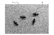
- the input unit 12 receives an input image 40 illustrated in FIG. 2 and outputs it to the control unit 14 .
- the input image 40 includes the image of the recognition target 50 and is used for generating teacher data.
- the input unit 12 may accept input of one image as the input image 40, or may accept input of two or more images.
- the image processing unit 141 of the control unit 14 performs image processing aimed at reducing noise included in the input image 40 acquired from the input unit 12 and enhancing the contour of the recognition target 50 .
- the image processing unit 141 may perform processing such as contrast correction, gamma correction, bilateral filtering, or Gaussian filtering, for example.
- the image processing unit 141 selects processing or adjusts processing parameters so that the outline of the recognition target 50 is emphasized according to the content of the acquired input image 40 or the purpose of the image processing.
- the processing executed by the image processing unit 141 is also called preprocessing.
- An image obtained by performing preprocessing on the input image 40 is also referred to as a preprocessed image 41 .
- a preprocessed image 41 is illustrated in FIG.
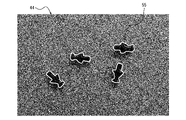
- the initial polygon generator 142 of the control unit 14 generates an initial polygon 51 for the preprocessed image 41, as illustrated in FIG.
- the initial polygon 51 is a line representing the contour of the recognition target 50 .
- the image in which the initial polygons 51 are generated is also called a polygon generated image 42 .
- the initial polygon generator 142 generates an initial polygon 51 for the input image 40 when preprocessing is not performed.
- the process of generating the initial polygon 51 is included in the first process.
- the initial polygon generation unit 142 may perform the processing described below in order to generate the initial polygon 51 .
- the initial polygon generating unit 142 uses a pre-trained machine learning model to execute inference of object detection by machine learning on the input image 40 or the preprocessed image 41 that has been input, and converts the output contour information into an initial polygon. It may be used as polygon 51.
- the machine learning model used for inference to generate the initial polygon 51 is also called a second machine learning model.
- the initial polygon generation unit 142 uses the initial polygon 51 obtained by machine learning inference as a cost function to generate a polygon generated image.
- Graph cut processing for 42 may also be performed.
- the initial polygon generator 142 may use the data obtained by the graph cutting process as the initial polygon 51 .
- the initial polygon generator 142 designates a region for the input image 40 or the preprocessed image 41, extracts the background color data of the designated region, and obtains the foreground contour using the hue value of the background color data. may be used as the initial polygon 51.
- the method of extracting the foreground in this manner is a general method known for chromakey synthesis and the like. If the background of the image has a simple structure, the outline can be extracted at high speed even if there are multiple objects in the foreground as the recognition target 50 .
- the initial polygon generator 142 may apply the graph cut processing to the cost function created by the user and use the obtained data as the initial polygon 51 .
- the training data generation device 10 may receive an input designated by the user as to which process the initial polygon generation section 142 is to perform.
- Input unit 12 may include a user interface.
- the input unit 12 may present a selection screen as shown in FIG. 5 to the user and receive an input from the user for selecting a process.
- Each mode illustrated in FIG. 5 may be associated with information specifying which of the processes described above is to be executed, or may be associated with parameters specified when executing each process described above.
- the initial polygon generation unit 142 may generate the initial polygon 51 by foreground extraction using hue data, graph cutting, inference by machine learning, or a combination of these methods.
- Foreground extraction using hue data can also be called background removal based on hue information.
- Inference by machine learning can also be called inference of detection of the recognition target 50 by the second machine learning model.
- the initial polygon generation unit 142 performs a predetermined algorithm including at least one of background removal based on hue information, graph cut, and inference of detection of the recognition target 50 by the second machine learning model. may be used to generate polygon data.
- the initial polygon generator 142 may specify at least a partial area of the input image 40 and generate the initial polygon 51 within that area.
- a region designated as a target for generating the initial polygon 51 is also called a first region.
- a super pixel is known as an image processing method that extracts a portion of the input image 40 with a high luminance gradient and divides the image into a plurality of regions along contour lines.
- the superpixel unit 143 of the control unit 14 performs superpixels on a designated region 53 including at least a portion of the input image 40 to divide it into segments 52, as illustrated in FIGS.
- the superpixel unit 143 associates segmentation information identifying the boundaries of the generated segments 52 with the image. Images with associated segmentation information are also referred to as segment images 43 . Execution of superpixels is included in the second processing.
- the superpixel unit 143 may appropriately set the specified area 53 (see FIG. 6) targeted for superpixels.
- the specified area 53 is also called a second area.
- the super-pixel unit 143 may set the designated area 53 so as to include all the initial polygons 51 based on the data of the initial polygons 51 .
- the superpixel unit 143 generates a segment 52 with a range including four recognition targets 50 as the specified region 53 .
- the superpixel unit 143 may set the designated area 53 so as to individually include each initial polygon 51 .
- the superpixel unit 143 generates a segment 52 by using a range that individually includes each recognition target 50 as the specified region 53 .
- the superpixel unit 143 may receive an input specifying a range from the user and set the specified area 53 based on the user's specification. When the super-pixel unit 143 automatically sets the specified area 53 , it may be possible to set how large the specified area 53 is to be relative to the area of the initial polygon 51 . The superpixel unit 143 can speed up superpixel processing and reduce the load of superpixel processing by limiting the processing range instead of the entire image.
- a polygon correction unit 144 of the control unit 14 adds a segment 52 to the initial polygon 51 or deletes a part of the segment 52 from the initial polygon 51 based on the initial polygon 51 .
- the polygon correction unit 144 corrects the initial polygon 51 or deletes the data of the initial polygon 51 to which the label is not attached based on the user's operation for the portion where the initial polygon 51 does not accurately capture the outline of the recognition target 50 . or For example, as shown in FIG. 8, when the initial polygon 51 includes the shadow of the recognition target 50 as the outline of the recognition target 50, the polygon correction unit 144 designates the segment 52 marked with an asterisk as the deletion target region 54. designated and deleted from the initial polygon 51.
- the polygon correction unit 144 can generate a corrected polygon 55 that accurately captures the contour of the recognition target 50 as shown in FIG.
- the image associated with the information of the modified polygon 55 is also called the polygon modified image 44 .
- the polygon correction unit 144 may add the asterisked segment 52 as the initial polygon 51 to generate the modified polygon 55 .
- the polygon correction unit 144 can generate a corrected polygon 55 representing a contour close to the true contour of the recognition target 50 by removing the deletion target region 54 from the range surrounded by the initial polygon 51 .
- the polygon correction unit 144 may correct the initial polygon 51 based on the segmentation information generated by the superpixel unit 143, in addition to correcting the initial polygon 51 based on the designation of arbitrary pixels or regions by the user. For example, when an arbitrary pixel value is specified by the user, the polygon correction unit 144 can generate a corrected polygon 55 by correcting the segment 52 including the specified pixel value as the foreground or background.
- the initial polygon 51 can be sped up. For example, in FIG. 10, by designating the deletion target area 54 in the range surrounded by the initial polygon 51 as the background, the portion corresponding to the shadow of the recognition target 50 can be corrected with less operation.
- the polygon correction unit 144 may automatically correct the initial polygon 51.
- the labeling unit 145 of the control unit 14 gives the input image 40 or the preprocessed image 41 label information describing the recognition target 50 whose outline is represented by the initial polygon 51 or the modified polygon 55 .
- the labeling unit 145 gives label information to the initial polygon 51 or the modified polygon 55.
- the label assigning unit 145 may receive an input of label information from the user and assign label information specified by the user.
- the label assigning unit 145 may assign label information determined by inference based on machine learning.
- the label assigning unit 145 may assign the label information at any timing during the period from the acquisition of the input image 40 from the input unit 12 to the generation of the corrected polygon 55 by the polygon correcting unit 144 .
- the teacher data generation unit 146 of the control unit 14 generates data that associates the input image 40, the data of the correction polygon 55, and the label information as teacher data, and outputs the data to the output unit 16.
- control unit 14 When the control unit 14 acquires a plurality of input images 40 from the input unit 12, it executes each of the above-described processes for each input image 40 to generate teacher data.
- the output unit 16 outputs the teacher data acquired from the control unit 14 to an external device.
- the training data generation device 10 can generate training data by generating and correcting the initial polygons 51 .
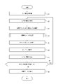
- the controller 14 of the training data generation device 10 may execute the training data generation method including the procedure of the flowchart illustrated in FIG. 11 .
- the teacher data generation method may be implemented as a teacher data generation program that is executed by a processor that constitutes the controller 14 of the teacher data generation device 10 .
- the teacher data generation program may be stored in a non-transitory computer-readable medium.
- the control unit 14 of the training data generation device 10 acquires the input image 40 via the input unit 12 (step S1).
- the control unit 14 performs preprocessing on the input image 40 (step S2).
- the control unit 14 selects a generation mode for the initial polygon 51 (step S3).
- the control unit 14 selects one of modes of inference by machine learning, foreground extraction using hue data, and graph cut.
- the control unit 14 generates an initial polygon 51 (step S4).
- the control unit 14 generates the initial polygon 51 in the mode selected in the procedure of step S3.
- the control unit 14 executes the procedure of the flow chart shown in FIG. 12 in order to generate the initial polygon 51 in the machine learning inference mode.
- the control unit 14 acquires a machine learning model (step S11).
- the control unit 14 performs inference to detect the contour of the recognition target 50 from the input image 40 using the machine learning model (step S12).
- the control unit 14 determines whether to execute graph cutting (step S13). If the control unit 14 does not determine to execute the graph cut (step S13: NO), the process proceeds to step S15. When determining to execute the graph cut (step S13: YES), the control unit 14 executes the graph cut on the input image 40 using the contour detected by executing the inference as the cost function (step S14).
- the control unit 14 generates an initial polygon 51 based on the contour of the recognition target 50 detected by executing the inference (step S15). After executing the procedure of step S15, the control unit 14 ends the execution of the flowchart of FIG. 12 and proceeds to the procedure of step S5 of FIG.
- the control unit 14 executes the procedure of the flowchart shown in FIG. 13 in order to generate the initial polygon 51 in the foreground extraction mode using hue data.
- the control unit 14 designates the range from which the foreground is to be extracted (step S21).
- the control unit 14 acquires the background color in the specified range as the peripheral hue (step S22).
- the control unit 14 removes the background (step S23).
- the control unit 14 generates the initial polygon 51 based on the outline of the foreground extracted by removing the background (step S24). After executing the procedure of step S24, the control unit 14 ends the execution of the flowchart of FIG. 13 and proceeds to the procedure of step S5 of FIG.
- the control unit 14 executes the procedure of the flowchart shown in FIG. 14 in order to generate the initial polygon 51 in graph cut mode.
- the control unit 14 generates a mask (step S31).
- the control unit 14 executes graph cutting based on the mask (step S32).
- the control unit 14 determines whether or not the graph cut has ended (step S33). If the graph cut has not ended (step S33: NO), the control unit 14 returns to the procedure of step S31.
- the control unit 14 When the graph cut is finished (step S33: YES), the control unit 14 generates the initial polygon 51 based on the extraction result of the recognition target 50 by the graph cut (step S34). After executing the procedure of step S34, the control unit 14 ends the execution of the flowchart of FIG. 14 and proceeds to the procedure of step S5 of FIG.
- the control unit 14 executes superpixel (step S5).
- the control unit 14 modifies the polygon based on the segmentation information specifying the segments 52 generated by the superpixels (step S6).
- the control unit 14 gives label information (step S7).
- the control unit 14 determines whether there is another input image 40 for generating teacher data, that is, whether there is next image data (step S8).
- step S8: YES the control unit 14 returns to the procedure of step S2 and processes the next input image 40.
- FIG. When the next input image 40 does not exist (step S8: NO), the control unit 14 associates the data of the polygon generated in the input image 40 with the label information given to the polygon to the input image 40, and creates teacher data. Generate (step S9). After executing the procedure of step S9, the control unit 14 ends the execution of the procedure of the flowchart of FIG.
- the control unit 14 may execute the label information addition procedure in step S7 at any timing from after step S1 to after step S6.
- the control unit 14 gives the label information to the input image 40 when giving the label information before generating the initial polygon 51 .
- the control unit 14 assigns the label information assigned to the input image 40 to the generated initial polygon 51 .
- the control unit 14 may extract the recognition target 50 that matches the label information given to the input image 40 and generate the initial polygon 51 for the extracted recognition target 50 .
- the control unit 14 may execute the procedure for generating the initial polygons 51 in step S4 of FIG. 11 after the procedure for executing superpixels in step S5. In this case, the control unit 14 can generate the initial polygon 51 based on the segmentation information.
- the control unit 14 may perform superpixeling on the entire image again when correcting polygons. For example, if the control unit 14 performs super-pixels only on a partial range of the input image 40 in the procedure of step S5, no segmentation information is associated outside the super-pixels range. Therefore, it can be envisioned in various embodiments that control unit 14 performs superpixeling again on the entire image when modifying polygons.
- the initial polygon 51 is modified based on segmentation information specifying segments 52 set by performing superpixels on the input image 40 or preprocessed image 41 that has been input. By doing so, the initial polygon 51 is corrected with high accuracy so that the contour represented by the corrected polygon 55 approaches the true contour of the recognition target 50 . Also, the time required to correct the initial polygon 51 is shortened.
- teacher data generation device 10 and the teacher data generation method according to the present embodiment polygons can be generated with high accuracy. As a result, robustness against non-identical objects may be improved.
- a configuration can be considered in which training data is generated by detecting the contour of the foreground from an arbitrary background with high accuracy.
- this configuration if one image contains images of a plurality of objects, the work of inputting the shape of the foreground region increases.
- the input of the shape of the foreground region can be omitted by generating the initial polygon 51 . As a result, the user's workload and working time can be reduced.
- a configuration that uses a machine learning model to label the segmentation of each pixel in an image can be considered.
- work time and work cost for preparing initial teacher data as well as computational load and computational cost for executing learning for generating a machine learning model are incurred.
- the teacher data generation device 10 and the teacher data generation method according to the present embodiment by generating the initial polygon 51 and correcting it, polygons can be generated with high accuracy without user's work. As a result, the user's workload and working time can be reduced.
- the teacher data generation device 10 may sequentially generate teacher data for each of the plurality of input images 40 .
- the teacher data generation device 10 may feed back correction data of the initial polygon 51 in the input image 40 processed in the earliest order to generate the initial polygon 51 in the input image 40 processed in the latter order.
- the accuracy of the initial polygon 51 is enhanced.
- the workload or computational load of modifying the initial polygon 51 can be reduced.
- the training data generation device 10 generates a corrected polygon 55 by deleting the shadow portion from the initial polygon 51 in the polygon correction section 144 of the control section 14 .
- the control unit 14 characterizes the image of the deleted shadow portion as corrected data, and feeds back the data characterizing the corrected data to the generation of the initial polygon 51 in the input image 40 to be processed later.
- the control unit 14 can detect the shadow portion from the input image 40 based on the data characterizing the image of the shadow portion as correction data, and remove the shadow portion from the beginning when generating the initial polygon 51 .
- the data characterizing the modified data including the image of the modified portion such as the shadow portion includes, for example, pixel value information, texture information, or shape information of the image.
- Data characterizing the modified data of the initial polygon 51 is also referred to as characterization data. Characterization data can also be used as a condition for selecting the type of image processing or determining parameters for image processing in the image processing unit 141 of the control unit 14 . That is, the image processing unit 141 may modify the parameters applied to the preprocessing for the input image 40 to be processed later, based on the modified data of the polygon data. Parameters that apply to preprocessing are also referred to as preprocessing parameter values.
- the control unit 14 may process a plurality of input images 40 including images of the same type of object.
- the machine learning model used for inference is an overrun of the input image 40.
- a trained machine learning model can be used. For example, when the control unit 14 satisfies a predetermined condition when starting to process the next input image 40, the control unit 14 generates the initial polygon 51 by learning using teacher data generated based on the input image 40 that has already been processed. You may generate and transfer a machine learning model to be used for
- the control unit 14 Based on the difference between the initial polygon 51 (polygon data) and the corrected polygon 55 (corrected polygon data) in the previously executed processing of the input image 40, the control unit 14 inputs as preprocessing of the next input image 40 to be processed. Image 40 may be corrected. Further, the control unit 14 controls the input image 40 to be processed next based on the correction data from the initial polygon 51 (polygon data) to the corrected polygon 55 (corrected polygon data) in the processing of the input image 40 previously executed. The input image 40 may be corrected as processing.
- the control unit 14 may feed back the correction data of the initial polygon 51 as described above by executing the teaching data generation method including the procedures of the flow charts illustrated in FIGS. 15 and 16 .
- the control unit 14 acquires the input image 40 via the input unit 12 (step S51).
- the control unit 14 performs preprocessing on the input image 40 (step S52).
- the control unit 14 selects a generation mode for the initial polygon 51 (step S53).
- the control unit 14 generates the initial polygon 51 (step S54).
- the control unit 14 generates the initial polygon 51 in the mode selected in the procedure of step S53.
- the control unit 14 may execute the procedure shown in any one of FIGS. 12, 13, and 14 in the procedure of step S54.
- Each procedure from steps S51 to S54 in FIG. 15 corresponds to each procedure from steps S1 to S4 in FIG.
- the control unit 14 automatically corrects the initial polygon 51 (step S55). Specifically, the control unit 14 may correct the initial polygon 51 based on correction data for the initial polygon 51 when the input image 40 was processed prior to the input image 40 currently being processed. The control unit 14 does not have to execute the procedure of step S55.
- the control unit 14 executes superpixel (step S56).
- the control unit 14 modifies the polygon based on the segmentation information specifying the segments 52 generated by the superpixels (step S57).
- the control unit 14 gives label information (step S58).
- the control unit 14 determines whether there is another input image 40 for generating teacher data, that is, whether there is next image data (step S59). If the next input image 40 does not exist (step S59: NO), the control unit 14 associates the data of the polygon generated in the input image 40 with the label information given to the polygon for the input image 40, and creates teacher data.
- Generate step S60. After executing the procedure of step S60, the control unit 14 ends the execution of the procedure of the flowchart of FIG.
- Each procedure from steps S56 to S60 in FIG. 15 corresponds to each procedure from steps S5 to S9 in FIG.
- step S61 determines whether or not the polygon has been corrected in the processing of the previous input image 40 (step S61). If there is no polygon correction in the processing of the previous input image 40 (step S61: NO), the control unit 14 returns to step S52 to process the next input image 40.
- step S62 If the polygon has been modified in the processing of the previous input image 40 (step S61: YES), the control unit 14 characterizes the modified data (step S62). The control unit 14 learns correction data (step S63). The control unit 14 may generate a machine learning model that is used to generate the initial polygon 51 by learning correction data. After executing the procedure of step S ⁇ b>63 , the control unit 14 returns to the procedure of step S ⁇ b>52 to process the next input image 40 .
- the training data generation device 10 can improve the accuracy of the initial polygon 51 by feeding back the characterization data. Further, the training data generation device 10 can further improve the accuracy of the initial polygon 51 by automatically correcting the initial polygon 51 based on the characterization data. Further, the training data generation device 10 can enhance the outline of the recognition target 50 and make it easier to detect the initial polygon 51 by adjusting the parameters in the preprocessing of the input image 40 based on the characterized data. As a result, the accuracy of the initial polygon 51 is further improved.
- a storage medium on which the program is recorded for example, an optical disk, an optical Magnetic disk, CD-ROM, CD-R, CD-RW, magnetic tape, hard disk, memory card, etc.
- the implementation form of the program is not limited to an application program such as an object code compiled by a compiler or a program code executed by an interpreter. good.
- the program may or may not be configured so that all processing is performed only in the CPU on the control board.
- the program may be configured to be partially or wholly executed by another processing unit mounted on an expansion board or expansion unit added to the board as required.
- Embodiments according to the present disclosure are not limited to any specific configuration of the embodiments described above. Embodiments of the present disclosure extend to any novel feature or combination thereof described in the present disclosure or any novel method or process step or combination thereof described. be able to.
- Descriptions such as “first” and “second” in this disclosure are identifiers for distinguishing the configurations. Configurations that are differentiated in descriptions such as “first” and “second” in this disclosure may interchange the numbers in that configuration. For example, a first process can exchange identifiers “first” and “second” with a second process. The exchange of identifiers is done simultaneously. The configurations are still distinct after the exchange of identifiers. Identifiers may be deleted. Configurations from which identifiers have been deleted are distinguished by codes. The description of identifiers such as “first” and “second” in this disclosure should not be used as a basis for interpreting the order of the configuration or the existence of lower numbered identifiers.
- the configuration according to the present disclosure includes an input unit 12 that acquires at least one input image 40 that includes an image of the recognition target 50, and a first region of the input image 40 along the contour of a portion that is determined to be the image of the recognition target 50. a first process of generating polygon data, a second process of setting segments 52 obtained by dividing the input image 40 into areas based on the luminance gradient, and a correction of the polygon data based on the segments 52 set by the second process. It may be implemented as an image processing apparatus including a control unit 14 for generating modified polygon data.
- Teacher data generation device (12: input unit, 14: control unit, 16: output unit, 141: image processing unit, 142: initial polygon generation unit, 143: super pixel unit, 144: polygon correction unit, 145: label assignment part, 146: teacher data generation part) 40 Input image 41 Preprocessed image 42 Polygon generated image 43 Segment image 44 Polygon corrected image 50 Recognition object 51 Initial polygon 52 Segment 53 Designated area 54 Deleted area 55 Corrected polygon
Landscapes
- Engineering & Computer Science (AREA)
- Theoretical Computer Science (AREA)
- Computer Vision & Pattern Recognition (AREA)
- Physics & Mathematics (AREA)
- General Physics & Mathematics (AREA)
- Software Systems (AREA)
- Medical Informatics (AREA)
- Evolutionary Computation (AREA)
- Artificial Intelligence (AREA)
- Computing Systems (AREA)
- Data Mining & Analysis (AREA)
- General Engineering & Computer Science (AREA)
- Mathematical Physics (AREA)
- Health & Medical Sciences (AREA)
- Databases & Information Systems (AREA)
- General Health & Medical Sciences (AREA)
- Multimedia (AREA)
- Image Analysis (AREA)
Abstract
Description
本開示の一実施形態に係る教師データ生成装置10は、画素を有する画像データであって、認識対象50(図2等参照)の画像を含む画像データに対して画素の単位でセグメンテーションを行う機械学習モデルを生成するための教師データを作成する。セグメンテーションを行う機械学習モデルは、第1機械学習モデルとも称される。教師データ生成装置10は、認識対象50の画像を含む少なくとも1つの入力画像40(図2等参照)に対して認識対象50の輪郭を表すポリゴンを関連づけた情報を、教師データとして生成する。 (Configuration example of training data generation device 10)
A training
教師データ生成装置10の具体的な動作例が以下説明される。 (Example of Operation of Teacher Data Generation Device 10)
A specific operation example of the training
入力部12は、図2に例示される入力画像40の入力を受け付け、制御部14に出力する。入力画像40は、認識対象50の画像を含み、教師データの生成のために用いられる。入力部12は、入力画像40として、1枚の画像の入力を受け付けてもよいし、2枚以上の画像の入力を受け付けてもよい。 <Input image>
The
制御部14の画像処理部141は、入力部12から取得した入力画像40に含まれるノイズの低減、及び、認識対象50の輪郭の強調を目的とした画像処理を実行する。画像処理部141は、例えば、コントラスト補正、ガンマ補正、バイラテラルフィルタ、又はガウシアンフィルタ等の処理を実行してよい。画像処理部141は、取得した入力画像40の内容、又は、画像処理の目的に応じて、認識対象50の輪郭が強調されるように、処理を選択したり処理のパラメータを調整したりする。画像処理部141が実行する処理は、前処理とも称される。入力画像40に対して前処理を実行して得られた画像は、前処理画像41とも称される。前処理画像41が図3に例示される。 <Pretreatment>
The
制御部14の初期ポリゴン生成部142は、図4に例示されるように、前処理画像41に対して初期ポリゴン51を生成する。初期ポリゴン51は、認識対象50の輪郭を表す線である。初期ポリゴン51を生成した画像は、ポリゴン生成画像42とも称される。初期ポリゴン生成部142は、前処理が実行されない場合、入力画像40に対して初期ポリゴン51を生成する。初期ポリゴン51を生成する処理は、第1の処理に含まれる。初期ポリゴン生成部142は、初期ポリゴン51を生成するために、以下に述べる処理を実行してよい。 <Initial polygon generation>
The
初期ポリゴン生成部142は、事前学習済みの機械学習モデルを用いて、入力された入力画像40又は前処理画像41に対して機械学習による物体検出の推論を実行し、出力された輪郭情報を初期ポリゴン51として使用してよい。初期ポリゴン51を生成するための推論に用いられる機械学習モデルは、第2機械学習モデルとも称される。初期ポリゴン生成部142は、認識対象50の輪郭が複雑である場合に真の輪郭が出力されない可能性を考慮して、機械学習の推論によって得られた初期ポリゴン51をコスト関数として、ポリゴン生成画像42に対するグラフカット処理を更に実行してよい。初期ポリゴン生成部142は、グラフカット処理によって得られるデータを初期ポリゴン51として使用してよい。 <<Inference by machine learning>>
The initial
輪郭抽出において、複数の認識対象50を1つのクラスとして学習させて前景抽出に特化したモデルを事前学習済みモデルとして用いることが有効であると知られている。そこで、初期ポリゴン生成部142は、入力画像40又は前処理画像41に対して領域を指定し、指定した領域の背景色データを抽出し、背景色データの色相値を用いて得られる前景の輪郭を初期ポリゴン51として使用してよい。このように前景を抽出する手法は、クロマキー合成等で知られる一般的な手法である。画像の背景が単純な構造である場合、認識対象50としての前景の物体が複数ある場合においても高速に輪郭が抽出され得る。 <<Foreground Extraction Using Hue Data>>
In contour extraction, it is known to be effective to learn a plurality of recognition targets 50 as one class and use a model specialized for foreground extraction as a pre-trained model. Therefore, the
初期ポリゴン生成部142は、ユーザが作成したコスト関数をグラフカット処理にかけて、得られたデータを初期ポリゴン51として使用してもよい。 <<graph cut>>
The
教師データ生成装置10は、初期ポリゴン生成部142がどの処理を実行するか、ユーザが指定する入力を入力部12で受け付けてよい。入力部12は、ユーザインタフェースを含んでよい。例えば、入力部12は、図5に示されるような選択画面をユーザに提示してユーザから処理を選択する入力を受け付けてもよい。図5に例示される各モードは、上述した処理のどれを実行するか指定する情報に関連づけられてよいし、上述した各処理を実行する際に指定するパラメータに関連づけられてもよい。 << Select process >>
The training
スーパーピクセルは、入力画像40の輝度勾配が高い箇所を抽出し、輪郭線に沿って画像内を複数領域に分割する画像処理手法として知られている。制御部14のスーパーピクセル部143は、図6及び図7に例示されるように、入力画像40の少なくとも一部を含む指定領域53に対してスーパーピクセルを実行してセグメント52に分割する。スーパーピクセル部143は、生成したセグメント52の境界を特定するセグメンテーション情報を、画像に関連づける。セグメンテーション情報が関連づけられた画像は、セグメント画像43とも称される。スーパーピクセルの実行は、第2の処理に含まれる。 <Super pixel>
A super pixel is known as an image processing method that extracts a portion of the
制御部14のポリゴン修正部144は、初期ポリゴン51に基づいて、初期ポリゴン51に対するセグメント52の追加、又は、初期ポリゴン51からの一部のセグメント52の削除等を実行する。ポリゴン修正部144は、初期ポリゴン51が認識対象50の輪郭を正確に捉えていない箇所について、ユーザの操作に基づいて初期ポリゴン51を修正したり、ラベルを付与しない初期ポリゴン51のデータを削除したりする。例えば図8に示されるように、初期ポリゴン51が認識対象50の輪郭として認識対象50の影も含んでいる場合、ポリゴン修正部144は、星印が付されたセグメント52を削除対象領域54として指定し、初期ポリゴン51から削除する。ポリゴン修正部144は、削除対象領域54を初期ポリゴン51から削除することによって、図9に例示されるように認識対象50の輪郭を正確にとらえた修正ポリゴン55を生成できる。修正ポリゴン55の情報が関連づけられた画像は、ポリゴン修正画像44とも称される。なお、初期ポリゴン51が、認識対象50の輪郭を完全に含んでいない場合、すなわち星印が付されたセグメント52が認識対象50の物体の輪郭を形成している場合には、ポリゴン修正部144は、星印が付されたセグメント52を初期ポリゴン51として追加して修正ポリゴン55を生成してもよい。 <Polygon Correction>
A
教師データ生成装置10の制御部14は、図11に例示されるフローチャートの手順を含む教師データ生成方法を実行してもよい。教師データ生成方法は、教師データ生成装置10の制御部14を構成するプロセッサに実行させる教師データ生成プログラムとして実現されてもよい。教師データ生成プログラムは、非一時的なコンピュータ読み取り可能な媒体に格納されてよい。 (Sample procedure for generating training data)
The
制御部14は、機械学習による推論のモードで初期ポリゴン51を生成するために、図12に示されるフローチャートの手順を実行する。 <Inference by machine learning>
The
制御部14は、色相データを用いた前景抽出のモードで初期ポリゴン51を生成するために、図13に示されるフローチャートの手順を実行する。 <Foreground extraction using hue data>
The
制御部14は、グラフカットのモードで初期ポリゴン51を生成するために、図14に示されるフローチャートの手順を実行する。 <Graph cut>
The
以上述べてきたように、本実施形態に係る教師データ生成装置10及び教師データ生成方法によれば、初期ポリゴン51を生成して修正することによって、認識対象50の輪郭を表すポリゴンを描画するためにかかる時間が短縮される。また、認識対象50を前景として認識して初期ポリゴン51を生成するためのユーザ操作が減少する。 (Brief Summary)
As described above, according to the training
以下、他の実施形態が説明される。 (Other embodiments)
Other embodiments are described below.
教師データ生成装置10は、複数の入力画像40それぞれについて教師データを順次生成することがある。この場合、教師データ生成装置10は、早い順番で処理した入力画像40における初期ポリゴン51の修正データを、後の順番で処理する入力画像40における初期ポリゴン51の生成にフィードバックしてよい。このようにすることで、初期ポリゴン51の精度が高められる。その結果、初期ポリゴン51の修正にかかる作業負荷又は計算負荷が低減し得る。 <Feedback of Correction Data of
The teacher
40 入力画像
41 前処理画像
42 ポリゴン生成画像
43 セグメント画像
44 ポリゴン修正画像
50 認識対象
51 初期ポリゴン
52 セグメント
53 指定領域
54 削除領域
55 修正ポリゴン 10 Teacher data generation device (12: input unit, 14: control unit, 16: output unit, 141: image processing unit, 142: initial polygon generation unit, 143: super pixel unit, 144: polygon correction unit, 145: label assignment part, 146: teacher data generation part)
40
Claims (14)
- 認識対象の画像を含む少なくとも1つの入力画像を取得する入力部と、
前記入力画像の第1領域から前記認識対象の画像と判断された部分の輪郭に沿ったポリゴンデータの生成を行う第1の処理と、前記入力画像を輝度勾配に基づき領域分割したセグメントを設定する第2の処理と、前記第2の処理で設定したセグメントに基づき前記ポリゴンデータを修正した修正ポリゴンデータの生成と、前記入力画像に対するラベル情報の付与とを実行し、教師データを生成する制御部と、
前記教師データを出力する出力部と
を備える教師データ生成装置。 an input unit that acquires at least one input image including an image to be recognized;
A first process of generating polygon data along the contour of the portion determined to be the image to be recognized from the first area of the input image, and setting segments obtained by dividing the input image into areas based on luminance gradients. A control unit that executes a second process, generates modified polygon data by modifying the polygon data based on the segments set in the second process, and adds label information to the input image to generate teacher data. When,
and an output unit that outputs the training data. - 前記第1の処理において、前記入力画像に含まれる前景と背景の認識に基づいて前記ポリゴンデータの生成を行い、
前記第2の処理において、前記入力画像を前記セグメントに分割するスーパーピクセルを実行する、請求項1に記載の教師データ生成装置。 generating the polygon data based on recognition of the foreground and background included in the input image in the first processing;
2. The training data generating apparatus according to claim 1, wherein said second processing performs super-pixel dividing said input image into said segments. - 前記制御部は、生成された前記ポリゴンデータに対応する部分を含む前記入力画像の第2領域に前記第2の処理を行い、前記第2の処理で設定されたセグメントに基づき修正して生成した前記修正ポリゴンデータに対応する前記入力画像の部分に対して前記ラベル情報の付与を実行する、請求項1又は2に記載の教師データ生成装置。 The control unit performs the second processing on a second region of the input image including a portion corresponding to the generated polygon data, and corrects and generates a segment based on the segment set in the second processing. 3. The teacher data generation device according to claim 1, wherein the label information is added to the portion of the input image corresponding to the modified polygon data.
- 前記制御部は、前記入力画像のうち前記ポリゴンデータを生成した部分を対象として前記第2の処理を実行する、請求項3に記載の教師データ生成装置。 4. The teacher data generation device according to claim 3, wherein said control unit executes said second processing on a portion of said input image for which said polygon data has been generated.
- 前記制御部は、前記第2領域を前記第1領域よりも小さく設定する、請求項3又は4に記載の教師データ生成装置。 The teacher data generation device according to claim 3 or 4, wherein the control unit sets the second area to be smaller than the first area.
- 前記制御部は、前記入力画像のうち前記認識対象を含む領域を対象として前記第2の処理を行うことによって前記セグメントを設定し、前記第2の処理を行った前記入力画像の領域における前記ポリゴンデータの作成を行う、請求項1又は2に記載の教師データ生成装置。 The control unit sets the segment by performing the second processing on a region including the recognition target in the input image, and sets the segment in the region of the input image subjected to the second processing. 3. The teacher data generation device according to claim 1, which creates data.
- 前記入力画像に前記ラベル情報を付与し、前記ラベル情報に適合する前記ポリゴンデータを生成する、請求項1から6までのいずれか一項に記載の教師データ生成装置。 The teacher data generation device according to any one of claims 1 to 6, wherein the input image is given the label information, and the polygon data conforming to the label information is generated.
- 前記制御部は、前記第1の処理において、色相情報に基づく背景除去、グラフカット、及び、第2機械学習モデルによる前記認識対象の検出の推論のうち少なくとも1つを含む所定のアルゴリズムに基づいて、前記ポリゴンデータを生成する、請求項1から7までのいずれか一項に記載の教師データ生成装置。 The control unit, in the first processing, based on a predetermined algorithm including at least one of background removal based on hue information, graph cut, and inference of detection of the recognition target by a second machine learning model 8. The teacher data generation device according to claim 1, wherein the polygon data is generated.
- 前記制御部は、前記所定のアルゴリズムとして、前記認識対象の検出の推論で得られた前記認識対象の輪郭をコスト関数として前記グラフカットを実行する、請求項8に記載の教師データ生成装置。 9. The training data generation device according to claim 8, wherein the control unit executes the graph cut using, as the predetermined algorithm, the contour of the recognition target obtained by inference of detection of the recognition target as a cost function.
- 前記制御部は、前記第2の処理で設定したセグメントに基づき前記ポリゴンデータを修正した結果に基づいて、前記第2機械学習モデルを学習させる、請求項8又は9に記載の教師データ生成装置。 10. The teacher data generation device according to claim 8 or 9, wherein the control unit learns the second machine learning model based on a result of correcting the polygon data based on the segments set in the second process.
- 前記制御部は、前記ポリゴンデータと前記修正ポリゴンデータの差分又は前記修正ポリゴンデータへの修正データに基づき、入力される前記入力画像を補正する、請求項1から10までのいずれか一項に記載の教師データ生成装置。 11. The control unit according to any one of claims 1 to 10, wherein the controller corrects the input image based on a difference between the polygon data and the corrected polygon data or correction data for the corrected polygon data. teacher data generator.
- 前記制御部は、ポリゴンデータの修正データに基づいて、後で処理される前記入力画像に対する前処理に適用する前処理パラメータ値を修正する、請求項1から11までのいずれか一項に記載の教師データ生成装置。 12. The control unit according to any one of claims 1 to 11, wherein the controller modifies a preprocessing parameter value applied to preprocessing for the input image to be processed later, based on correction data of polygon data. Teacher data generator.
- 認識対象の画像を含む少なくとも1つの入力画像を取得することと、
前記入力画像の第1領域から前記認識対象の画像と判断された部分の輪郭に沿ったポリゴンデータの生成を行う第1の処理を実行することと、
前記入力画像を輝度勾配に基づき領域分割したセグメントを設定する第2の処理を実行することと、
前記第2の処理で設定したセグメントに基づき前記ポリゴンデータを修正した修正ポリゴンデータを生成することと、
前記入力画像に対してラベル情報を付与することと、
教師データを生成して出力することと
を含む教師データ生成方法。 obtaining at least one input image including an image to be recognized;
executing a first process of generating polygon data along the contour of the portion determined to be the image to be recognized from the first region of the input image;
performing a second process of setting segments obtained by dividing the input image into regions based on luminance gradients;
generating corrected polygon data by correcting the polygon data based on the segments set in the second process;
assigning label information to the input image;
and generating and outputting teacher data. - 認識対象の画像を含む少なくとも1つの入力画像を取得する入力部と、
前記入力画像の第1領域から前記認識対象の画像と判断された部分の輪郭に沿ったポリゴンデータの生成を行う第1の処理と、前記入力画像を輝度勾配に基づき領域分割したセグメントを設定する第2の処理と、前記第2の処理で設定したセグメントに基づき前記ポリゴンデータを修正した修正ポリゴンデータの生成とを実行する制御部と、
を備える画像処理装置。 an input unit that acquires at least one input image including an image to be recognized;
A first process of generating polygon data along the contour of the portion determined to be the image to be recognized from the first area of the input image, and setting segments obtained by dividing the input image into areas based on luminance gradients. a control unit that executes a second process and generates corrected polygon data by correcting the polygon data based on the segments set in the second process;
An image processing device comprising:
Priority Applications (3)
| Application Number | Priority Date | Filing Date | Title |
|---|---|---|---|
| JP2023523453A JP7467773B2 (en) | 2021-05-24 | 2022-05-20 | Teacher data generating device, teacher data generating method, and image processing device |
| CN202280037072.6A CN117377985A (en) | 2021-05-24 | 2022-05-20 | Teaching data generation device, teaching data generation method, and image processing device |
| EP22811267.8A EP4350610A1 (en) | 2021-05-24 | 2022-05-20 | Teaching data generation device, teaching data generation method, and image processing device |
Applications Claiming Priority (2)
| Application Number | Priority Date | Filing Date | Title |
|---|---|---|---|
| JP2021-087206 | 2021-05-24 | ||
| JP2021087206 | 2021-05-24 |
Publications (1)
| Publication Number | Publication Date |
|---|---|
| WO2022249997A1 true WO2022249997A1 (en) | 2022-12-01 |
Family
ID=84229873
Family Applications (1)
| Application Number | Title | Priority Date | Filing Date |
|---|---|---|---|
| PCT/JP2022/021023 WO2022249997A1 (en) | 2021-05-24 | 2022-05-20 | Teaching data generation device, teaching data generation method, and image processing device |
Country Status (4)
| Country | Link |
|---|---|
| EP (1) | EP4350610A1 (en) |
| JP (1) | JP7467773B2 (en) |
| CN (1) | CN117377985A (en) |
| WO (1) | WO2022249997A1 (en) |
Citations (7)
| Publication number | Priority date | Publication date | Assignee | Title |
|---|---|---|---|---|
| JP2012085233A (en) * | 2010-10-14 | 2012-04-26 | Sharp Corp | Video processing device, video processing method, and program |
| JP2017220098A (en) * | 2016-06-09 | 2017-12-14 | 日本電信電話株式会社 | Image processing device, image processing method, image processing program and image recognition system |
| JP2018510320A (en) * | 2014-12-09 | 2018-04-12 | ビーエーエスエフ ソシエタス・ヨーロピアBasf Se | Optical detector |
| JP2019061658A (en) * | 2017-08-02 | 2019-04-18 | 株式会社Preferred Networks | Area discriminator training method, area discrimination device, area discriminator training device, and program |
| JP2019101535A (en) | 2017-11-29 | 2019-06-24 | コニカミノルタ株式会社 | Teacher data preparation device and method thereof and image segmentation device and method thereof |
| CN111489357A (en) * | 2019-01-29 | 2020-08-04 | 广州市百果园信息技术有限公司 | Image segmentation method, device, equipment and storage medium |
| WO2020174862A1 (en) * | 2019-02-28 | 2020-09-03 | ソニー株式会社 | Information processing device, information processing method, and information processing system |
-
2022
- 2022-05-20 EP EP22811267.8A patent/EP4350610A1/en active Pending
- 2022-05-20 CN CN202280037072.6A patent/CN117377985A/en active Pending
- 2022-05-20 JP JP2023523453A patent/JP7467773B2/en active Active
- 2022-05-20 WO PCT/JP2022/021023 patent/WO2022249997A1/en active Application Filing
Patent Citations (7)
| Publication number | Priority date | Publication date | Assignee | Title |
|---|---|---|---|---|
| JP2012085233A (en) * | 2010-10-14 | 2012-04-26 | Sharp Corp | Video processing device, video processing method, and program |
| JP2018510320A (en) * | 2014-12-09 | 2018-04-12 | ビーエーエスエフ ソシエタス・ヨーロピアBasf Se | Optical detector |
| JP2017220098A (en) * | 2016-06-09 | 2017-12-14 | 日本電信電話株式会社 | Image processing device, image processing method, image processing program and image recognition system |
| JP2019061658A (en) * | 2017-08-02 | 2019-04-18 | 株式会社Preferred Networks | Area discriminator training method, area discrimination device, area discriminator training device, and program |
| JP2019101535A (en) | 2017-11-29 | 2019-06-24 | コニカミノルタ株式会社 | Teacher data preparation device and method thereof and image segmentation device and method thereof |
| CN111489357A (en) * | 2019-01-29 | 2020-08-04 | 广州市百果园信息技术有限公司 | Image segmentation method, device, equipment and storage medium |
| WO2020174862A1 (en) * | 2019-02-28 | 2020-09-03 | ソニー株式会社 | Information processing device, information processing method, and information processing system |
Also Published As
| Publication number | Publication date |
|---|---|
| EP4350610A1 (en) | 2024-04-10 |
| CN117377985A (en) | 2024-01-09 |
| JPWO2022249997A1 (en) | 2022-12-01 |
| JP7467773B2 (en) | 2024-04-15 |
Similar Documents
| Publication | Publication Date | Title |
|---|---|---|
| US9571697B2 (en) | Image processing device setting sharpness adjustment degrees for object regions and performing unsharp masking process | |
| CN105404846A (en) | Image processing method and apparatus | |
| US20220301239A1 (en) | Automatic coloring of line drawing | |
| JP6929322B2 (en) | Data expansion system, data expansion method, and program | |
| WO2019011342A1 (en) | Cloth identification method and device, electronic device and storage medium | |
| JP7173309B2 (en) | LEARNING METHOD, LEARNING PROGRAM AND LEARNING APPARATUS | |
| US20220292690A1 (en) | Data generation method, data generation apparatus, model generation method, model generation apparatus, and program | |
| US20220012514A1 (en) | Identification information assignment apparatus, identification information assignment method, and program | |
| WO2022249997A1 (en) | Teaching data generation device, teaching data generation method, and image processing device | |
| CN112307923A (en) | Partitioned expression migration method and system | |
| JP6900016B2 (en) | Image area extraction processing method and image area extraction processing program | |
| JP7282551B2 (en) | Information processing device, information processing method and program | |
| JP2017033556A (en) | Image processing method and electronic apparatus | |
| JP2020135653A (en) | Video image correction device and program | |
| JP2022147713A (en) | Image generation device, learning device, and image generation method | |
| JP2022156631A (en) | Image correction model generation method, image correction model generation program, and image correction model generation device | |
| JP2005217984A (en) | Image processing device | |
| JP7045103B1 (en) | Data Expansion Devices, Data Expansion Systems, and Data Expansion Programs | |
| KR102668050B1 (en) | Method, apparatus and computer programs for identifying illustration images | |
| JP7453668B2 (en) | Learning processing device, learning processing method, object detection device, object detection method, and program | |
| JPWO2019082283A1 (en) | Image analyzer | |
| US20220036040A1 (en) | Biometric recognition apparatus and biometric recognition method | |
| US20230071291A1 (en) | System and method for a precise semantic segmentation | |
| JPH07121710A (en) | Method and device for image segmentation | |
| JP4838224B2 (en) | Gradation conversion device and method, program |
Legal Events
| Date | Code | Title | Description |
|---|---|---|---|
| 121 | Ep: the epo has been informed by wipo that ep was designated in this application |
Ref document number: 22811267 Country of ref document: EP Kind code of ref document: A1 |
|
| WWE | Wipo information: entry into national phase |
Ref document number: 202280037072.6 Country of ref document: CN Ref document number: 18563739 Country of ref document: US Ref document number: 2023523453 Country of ref document: JP |
|
| NENP | Non-entry into the national phase |
Ref country code: DE |
|
| WWE | Wipo information: entry into national phase |
Ref document number: 2022811267 Country of ref document: EP |
|
| ENP | Entry into the national phase |
Ref document number: 2022811267 Country of ref document: EP Effective date: 20240102 |