WO2022244442A1 - Vehicle resting apparatus - Google Patents
Vehicle resting apparatus Download PDFInfo
- Publication number
- WO2022244442A1 WO2022244442A1 PCT/JP2022/012530 JP2022012530W WO2022244442A1 WO 2022244442 A1 WO2022244442 A1 WO 2022244442A1 JP 2022012530 W JP2022012530 W JP 2022012530W WO 2022244442 A1 WO2022244442 A1 WO 2022244442A1
- Authority
- WO
- WIPO (PCT)
- Prior art keywords
- seat
- resting
- main body
- vehicle
- resting device
- Prior art date
Links
- 230000000284 resting effect Effects 0.000 title claims abstract description 119
- 239000000463 material Substances 0.000 description 4
- 230000000694 effects Effects 0.000 description 3
- 238000010586 diagram Methods 0.000 description 2
- 239000004744 fabric Substances 0.000 description 2
- 238000000034 method Methods 0.000 description 1
- 230000004048 modification Effects 0.000 description 1
- 238000012986 modification Methods 0.000 description 1
- 230000003014 reinforcing effect Effects 0.000 description 1
- 230000002040 relaxant effect Effects 0.000 description 1
- 238000009958 sewing Methods 0.000 description 1
- 230000000087 stabilizing effect Effects 0.000 description 1
Images


Classifications
-
- A—HUMAN NECESSITIES
- A45—HAND OR TRAVELLING ARTICLES
- A45F—TRAVELLING OR CAMP EQUIPMENT: SACKS OR PACKS CARRIED ON THE BODY
- A45F3/00—Travelling or camp articles; Sacks or packs carried on the body
- A45F3/22—Hammocks; Hammock spreaders
-
- B—PERFORMING OPERATIONS; TRANSPORTING
- B60—VEHICLES IN GENERAL
- B60N—SEATS SPECIALLY ADAPTED FOR VEHICLES; VEHICLE PASSENGER ACCOMMODATION NOT OTHERWISE PROVIDED FOR
- B60N3/00—Arrangements or adaptations of other passenger fittings, not otherwise provided for
-
- B—PERFORMING OPERATIONS; TRANSPORTING
- B60—VEHICLES IN GENERAL
- B60N—SEATS SPECIALLY ADAPTED FOR VEHICLES; VEHICLE PASSENGER ACCOMMODATION NOT OTHERWISE PROVIDED FOR
- B60N3/00—Arrangements or adaptations of other passenger fittings, not otherwise provided for
- B60N3/06—Arrangements or adaptations of other passenger fittings, not otherwise provided for of footrests
Definitions
- minivans and light vans which are the main products of each vehicle manufacturer, can be arranged in a variety of ways, allowing you to stretch your legs in the car or create a space where you can lie down by making the luggage space fully flat. Such ingenuity has been made.
- Patent Document 1 the resting device disclosed in Patent Document 1 is intended for infants, and when used by adults, there are concerns about durability, and it is difficult to obtain a relaxing effect because the body cannot be completely accommodated. .
- the resting device main body is arranged in front of the user, and the second engaging portion is engaged with the backrest portion of the seat fixed to the vehicle. It is better to have a configuration in which it is stopped. With such a configuration, the resting equipment main body can support the lower body of the user.
- the resting device main body is configured to be arranged behind the user, and the second locking portion is provided corresponding to the seat. It can also be configured to be locked to the grip. With such a configuration, the rest device main body can support the user's upper body.
- the resting device main body has a width extending over two seat portions. With such characteristics, it can be used by a plurality of people, or can be used with the arms and legs spread out.
- a vehicle resting device for achieving the above object is provided with a first resting device main body arranged in front of a user, a second resting device main body arranged behind the user, and a second resting device main body arranged behind the user.
- a first resting device main body arranged in front of a user
- a second resting device main body arranged behind the user
- a second resting device main body arranged behind the user. 1 one end of the resting device main body, a first engaging portion provided at one end of the second resting device main body and engaged with the seat portion of the seat on which the user sits, and the other end of the first resting device main body a first resting device second engaging portion provided in the seat and engaged with the backrest portion of the seat located in the front row relative to the seat; and a second rest device second locking portion that is locked to the assist grip provided in the second resting device.
- the one end and the other end of the resting device main body of the vehicle resting device having the characteristics described above are provided with tacks in the width direction.
- the body of the resting equipment supports the supporting part so as to wrap it during use. Therefore, the supporting state can be stabilized.
- the vehicle resting device having the above characteristics, there are few restrictions on the seat form and arrangement, it is possible to quickly switch between the resting form and the moving form, and it can withstand use by adults. can.
- FIG. 5 is a perspective view showing a state in which the second locking portion is locked to the front row seat
- Fig. 10 is a perspective view showing a state in which the first locking portion is locked to the rear row seat
- Fig. 2 is a perspective view showing a state in which the vehicle rest device is installed between the front row seat and the rear row seat
- 1 is a perspective view showing a usage state of a vehicle resting device according to an embodiment
- FIG. It is a figure which shows the example in the case of equipping a 2nd latching
- FIG. 4 is a diagram showing a form of a vehicle rest device having a width that straddles two seats;
- FIG. 4 is a diagram showing a form of a vehicle rest device having a width that straddles two seats;
- FIG. 3 is a perspective view showing an example of locking the vehicle resting device according to the embodiment using a seat arranged at the rear of the vehicle.
- FIG. 4 is a diagram showing an example in which the first locking portion of the vehicle resting device is configured by a ring formed by a locking belt;
- FIG. 10 is a perspective view for explaining the mode of use of the vehicle rest device for supporting the upper half of the body of the user;
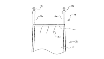
- the vehicle resting device 10 basically includes a resting device main body 12 , a first locking portion 14 and a second locking portion 16 .
- the rest device main body 12 is an element for supporting the lower half of the body of the user 50 (see FIG. 5) in use.
- any rectangular cloth may be used, and its length in the longitudinal direction (the length in the Y-axis direction in FIG. 1) is, for example, from the seat portion 42 of the back row seat 40 to the backrest portion 32 of the front row seat 30, particularly
- the length in the width direction (the length in the X-axis direction in FIG. 1) is sufficient to connect the shoulder portions 34 (both see FIG. 4 and the like). It is sufficient if the length is about the same as the width of .
- the resting device main body 12 is designed to improve strength by folding the four sides or by sewing with a reinforcing member applied.
- the sides forming the one end 12a to be engaged with the seat portion 42 of the back row seat 40 and the other end 12b to be engaged with the backrest portion 32 of the front row seat 30 each have a width.
- Tucks 12a1 and 12b1 are provided so as to shrink.
- the number of tucks 12b1 provided on the other end 12b side is greater than the number of tacks 12a1 provided on the one end 12a side, and the tip end side of the leg is securely wrapped. ing. Therefore, in the flat state, the width of the other end 12b side is narrower than the width of the one end 12a side.
- locking in this embodiment includes not only secure fixing and latching, but also a state of being supported in a close proximity state.
- the first locking portion 14 is provided on the one end 12 a side of the resting device main body 12 and is an element for locking the one end 12 a of the resting device main body 12 to the seat portion 42 of the back row seat 40 .
- it is composed of an adjustment belt 14a connected to one end 12a and a buckle 14b.
- the buckle 14b according to the embodiment may be any one that can be locked to an Isofix anchor (not shown) provided on the seat portion 42 of the rear row seat 40 . With such a configuration, the locking by the first locking portion 14 can be strengthened, and the safety during use can be improved.
- the buckle 14b is provided with a buckle joint, and the adjustment belt 14a is configured so that it can be locked and its length can be adjusted (positioning of the locking position), and the one end 12a of the resting device main body 12 and the buckle 14b It is configured so that the distance can be easily adjusted.
- the second locking portion 16 is provided on the side of the other end 12b of the resting device main body 12 and is an element for locking the other end 12b of the resting device main body 12 to the backrest portion 32 of the front row seat 30 .
- it is composed of a locking belt 16a connected to the other end 12b.
- the locking belt 16a shown in FIG. 1 is configured such that both ends of the belt are connected to the widthwise ends of the other end 12b of the resting device main body 12 to form a handle-like shape.
- the second locking portion 16 configured in this way can lock the other end 12b to the backrest portion 32 by passing the headrest pole 36 of the front row seat 30 through the handle-like portion.
- the vehicle rest device 10 having the basic configuration as described above can be used as follows. First, as shown in FIG. 2, the second locking portion 16 is hooked to the headrest pole 36 of the front row seat 30 to lock the other end 12b of the resting device main body 12 to the backrest portion 32 of the front row seat 30 .
- the height of the other end 12b of the resting device main body 12 can be determined by the length of the locking belt 16a forming the second locking portion 16.
- the locking belt 16a may be provided with a length adjusting means such as a foot.
- a buckle may be provided in addition to the grip (neither of which is shown) so that the handle-shaped second locking portion 16 can be opened. If the buckle is provided to enable the headrest to be opened, even if the projection surface of the headrest 38 is larger than the handle-shaped projection surface of the second locking portion 16, the headrest 38 can be locked without removing it. Become.
- the first locking portion 14 is locked to the Isofix anchor provided on the seat portion 42 of the back row seat 40 , and the one end 12 a of the rest device body 12 is attached to the seat portion 42 of the back row seat 40 . to lock.
- the resting device main body 12 spans the backrest portion 32 of the front row seat 30 and the seat portion 42 of the rear row seat 40 as shown in FIG. state.
- the tension of the resting device main body 12 can be adjusted by changing the length of the adjustment belt 14a in the first engaging portion 14.
- the first locking portion 14 is locked after the second locking portion 16 is locked.
- the second locking portion 16 may be locked later, and the order of locking is not limited in use.
- the front row seat 30 and the rear row seat 40 are provided. If it is a vehicle that has it, it can be used without restrictions on the seat configuration and seat arrangement.
- the first engaging portion 14 can be engaged with the rear seat 40 and the second engaging portion 16 can be engaged with the front seat 30, the seat can be used. can be switched quickly.
- most of the weight of the user 50 is supported by the seat portion 42 of the back row seat 40, and the vehicle resting device 10 itself supports only the weight of the lower body of the user 50, particularly the legs, so that it is suitable for use by adults. It is possible to ensure safety that can withstand even
- the tucks 12a1 and 12b1 are provided at the one end 12a and the other end 12b of the resting device main body 12.
- the one end 12a and the other end 12b may be provided with gathers instead of the tucks 12a1 and 12b1. This is because even with such a configuration, it is possible to obtain the effect of wrapping the supporting portion with the resting device main body 12 .
- the second locking portion 16 is shaped like a handle.
- the configuration is not limited to this as long as it can be engaged with the headrest pole 36 of the front row seat 30 .
- it may consist of a locking belt 16a and a hook 16b, or a carabiner (not shown) may be provided in place of the hook 16b.
- the locking destination of the second locking portion 16 is not limited to the headrest pole 36 either. For example, if there is an Isofix anchor on the front row seat 30, it is fixed with an adjustment belt and a buckle in the same manner as the first locking portion 14, and the rest tool is attached via the shoulder portion 34 of the backrest portion 32 of the front row seat 30. The other end 12b of the main body 12 may be engaged.
- first locking portion 14 and the second locking portion 16 may be locked to a seat that is in the immediate front-to-back relationship.
- the first locking portion 14 and the second locking portion 16 may be locked by using the front row seat 30 as a passenger seat and the rear row seat 40 as a seat located behind the driver's seat.
- the vehicle resting device 10 is sized for one person, it may be sized for two people.
- the resting device main body 12 has a width spanning two seats (the length in the X-axis direction in FIG.
- the portions 14 are provided in a number (for example, four) that can be engaged with the Isofix anchors provided on each seat.
- the second engaging portion 16 is engaged with the headrest poles 36 (36a, 36b) of the two front seats, as shown in FIG.
- the vehicle rest device 10 is configured to support the lower body of the user 50 by disposing the rest device main body 12 in front of the user 50 .
- the vehicle rest device 10 according to the present invention can also be configured to support the upper body of the user 50 .
- one end 12a of the resting device main body 12 is locked to the seat portion 42 of the seat (for example, the back row seat 40) via the first locking portion 14 (not shown in FIG. 10).
- the second locking portion 16 provided at the other end 12b of the resting device main body 12 is provided in correspondence with the seat on which the user 50 is seated (rear row seat 40 in the example shown in FIG. 10). It is configured to be lockable with the grip 48 .
- the assist grip 48 is mainly located on the inner wall ceiling side of the vehicle. For this reason, it is desirable that the second engaging portion 16 provided at the other end 12b of the resting device main body 12 is provided in the vicinity of the width direction end of the resting device main body 12 . This is because the width of the support area for the user 50 in the resting device main body 12 can be widened by widening the arrangement width of the base end portion of the second locking portion 16 .
- the resting device main body 12 constituting the vehicle resting device 10 having such a configuration on the backrest portion 44 side of the seat (rear row seat 40) on which the user 50 sits, that is, behind the user 50, the user can It is possible to support the upper body of 50.
- the vehicle resting device includes the resting device main body 12 (first resting device main body) for supporting the lower body of the user 50 and the resting device main body for supporting the upper body of the user 50 . 12 (second rest device body) may be combined.
- first resting device main body for supporting the lower body of the user 50
- second rest device body for supporting the upper body of the user 50
- a portion 14 is preferably provided.
- Other configurations may follow the configuration of the vehicle rest device 10 described above.
- the resting device according to the present invention is used as a vehicle resting device 10 for a vehicle, but if there are a front row seat 30 and a rear row seat 40, it can be applied to various types of vehicles or seats other than vehicles. can be done.
Abstract
[Problem] To provide a vehicle resting apparatus that has few restrictions on seat modes and placement, enables quick switching between a resting mode and a moving mode, and can withstand adult use. [Solution] The vehicle resting apparatus is characterized by including: a resting apparatus main body (12) for supporting the lower body of a user (50); a first latching portion (14) provided at one end (12a) of the resting apparatus main body (12) to latch the one end (12a) to a seat portion (42) of a rear row seat (40) of the vehicle; and a second latching portion (16) provided at the other end (12b) of the resting apparatus main body (12) to latch the other end (12b) to a backrest portion (32) of a front row seat (30) of the vehicle.
Description
本発明は、停車中の車内で休息するための休息具に係り、特にシートの配置等を大きく動かす事無く、足を伸ばしたい場合に好適な車両用休息具に関する。
The present invention relates to a resting device for resting in a stopped vehicle, and more particularly to a vehicle resting device suitable for those who want to stretch their legs without significantly moving the seat arrangement.
近年車両は、単なる移動手段だけでなく、パーソナルスペースを確保する事のできるプライベート空間として利用されることも多くなってきている。このため、停車中の車内で過ごす時間をいかに快適にできるかという点に注目が集まってきている。例えば、各車両メーカーで主力となっているミニバンや軽バンなどでは、様々なシートアレンジを可能とし、車内で足を伸ばしたり、荷室スペースをフルフラットにして横になれるスペースを作る事ができるような工夫が成されている。
In recent years, vehicles are becoming more and more used not only as a means of transportation, but also as a private space where personal space can be secured. For this reason, attention has been focused on how to make the time spent in a stopped car comfortable. For example, minivans and light vans, which are the main products of each vehicle manufacturer, can be arranged in a variety of ways, allowing you to stretch your legs in the car or create a space where you can lie down by making the luggage space fully flat. Such ingenuity has been made.
確かに、こうした車両はその目的に応じてシートアレンジを行う事ができるため、休息時間の快適化を図る事ができる。しかし、車内空間の快適化を求めるシートアレンジは多くの場合、シートを大きく移動させることとなるため、休息するための形態と、移動するための形態とを切り替えるのに時間や労力を要することとなる。また、通常のセダンタイプなどの車では、そうしたシートアレンジができない事が普通である。
Certainly, these vehicles can be arranged according to their purpose, so you can make your rest time more comfortable. However, in many cases, seat arrangements that seek to make the interior space more comfortable require a large amount of movement in the seat, so it takes time and effort to switch between the mode for resting and the mode for moving. Become. In addition, it is common that such a seat arrangement is not possible in cars such as ordinary sedans.
シートの形態や配置に制約が少なく、休息時の形態と移動時の形態とを素早く切り替える事ができるという観点から車両用の休息具に関する技術としては、特許文献1に開示されているような、いわゆるハンモック型の休息具が提案されている。特許文献1に開示されている休息具は、後列シートの背もたれ部分と前列シートの背もたれ部分にそれぞれ嵌装具を配置し、対を成す嵌装具の間にハンモック本体を掛け渡すという構成とされている。このため、シートの形態や配置に制約が少なく、使用時(休息時)、不使用時(例えば移動時)の切り替えも素早く行う事ができると考えられる。
There are few restrictions on the form and arrangement of the seat, and from the viewpoint of being able to quickly switch between the form for resting and the form for moving, as a technique related to a resting device for a vehicle, as disclosed in Patent Document 1, A so-called hammock-type resting device has been proposed. The resting device disclosed in Patent Document 1 has a configuration in which fittings are arranged on the backrest portion of the back row seat and the backrest portion of the front row seat, respectively, and the hammock body is hung between the pair of fittings. . For this reason, there are few restrictions on the shape and arrangement of the seat, and it is thought that switching between use (during rest) and non-use (for example, during movement) can be quickly performed.
しかし、特許文献1に開示されている休息具は、幼児を対象としたものであり、大人が使用する場合には耐久性が懸念されると共に、体が収まりきらず、リラックス効果を得る事が難しい。
However, the resting device disclosed in Patent Document 1 is intended for infants, and when used by adults, there are concerns about durability, and it is difficult to obtain a relaxing effect because the body cannot be completely accommodated. .
そこで本発明では、シート形態や配置に制約が少なく、休息時の形態と移動時の形態とを素早く切り替える事を可能とし、大人の使用にも耐え得る車両用休息具を提供することを目的とする。
SUMMARY OF THE INVENTION Accordingly, it is an object of the present invention to provide a resting device for a vehicle that has few restrictions on the form and arrangement of the seat, is capable of quickly switching between a resting form and a moving form, and can withstand the use of adults. do.
上記目的を達成するための本発明に係る車両用休息具は、少なくとも使用者の体の一部を支持する休息具本体と、前記休息具本体の一端に設けられ、前記使用者が着座するシートの座部に係止する第1係止部と、前記休息具本体の他端に設けられ、前記座部よりも高い位置に設けられた車内構造物に係止される第2係止部と、を備えることを特徴とする。
A vehicle resting device according to the present invention for achieving the above object comprises: a resting device main body supporting at least part of a user's body; and a seat provided at one end of the resting device main body on which the user sits. and a second locking portion provided at the other end of the rest device main body and engaged with an in-vehicle structure provided at a position higher than the seat portion. , is provided.
また、上記のような特徴を有する車両用休息具において前記休息具本体は、前記使用者
の前方に配置する構成とし、前記第2係止部は、車両に固定されたシートの背もたれ部に係止される構成とすると良い。このような構成とすることで、休息具本体は、使用者の下半身を支持することが可能となる。 Further, in the vehicle resting device having the characteristics described above, the resting device main body is arranged in front of the user, and the second engaging portion is engaged with the backrest portion of the seat fixed to the vehicle. It is better to have a configuration in which it is stopped. With such a configuration, the resting equipment main body can support the lower body of the user.
の前方に配置する構成とし、前記第2係止部は、車両に固定されたシートの背もたれ部に係止される構成とすると良い。このような構成とすることで、休息具本体は、使用者の下半身を支持することが可能となる。 Further, in the vehicle resting device having the characteristics described above, the resting device main body is arranged in front of the user, and the second engaging portion is engaged with the backrest portion of the seat fixed to the vehicle. It is better to have a configuration in which it is stopped. With such a configuration, the resting equipment main body can support the lower body of the user.
また、上記のような特徴を有する車両用休息具において前記休息具本体は、前記使用者の後方に配置する構成とし、前記第2係止部は、前記シートに対応して設けられているアシストグリップに係止される構成とすることもできる。このような構成とすることで、休息具本体は、使用者の上半身を支持することが可能となる。
Further, in the vehicle resting device having the characteristics as described above, the resting device main body is configured to be arranged behind the user, and the second locking portion is provided corresponding to the seat. It can also be configured to be locked to the grip. With such a configuration, the rest device main body can support the user's upper body.
また、上記のような特徴を有する車両用休息具において前記休息具本体は、2つのシート座部を跨ぐ幅を有するようにすると良い。このような特徴を有する事によれば、複数人での使用や、手足を広げた状態で使用する事が可能となる。
In addition, in the vehicle resting device having the characteristics described above, it is preferable that the resting device main body has a width extending over two seat portions. With such characteristics, it can be used by a plurality of people, or can be used with the arms and legs spread out.
また、上記目的を達成するための本発明に係る車両用休息具は、使用者の前方に配置する第1休息具本体と、前記使用者の後方に配置する第2休息具本体と、前記第1休息具本体の一端と、前記第2休息具本体の一端に設けられ、前記使用者が着座するシートの座部に係止する第1係止部と、前記第1休息具本体の他端に設けられ、前記シートよりも前列に位置するシートの背もたれ部に係止される第1休息具第2係止部と、前記第2休息具本体の他端に設けられ、前記シートに対応して設けられているアシストグリップに係止される第2休息具第2係止部と、を備えることを特徴とするものであっても良い。
In addition, a vehicle resting device according to the present invention for achieving the above object is provided with a first resting device main body arranged in front of a user, a second resting device main body arranged behind the user, and a second resting device main body arranged behind the user. 1 one end of the resting device main body, a first engaging portion provided at one end of the second resting device main body and engaged with the seat portion of the seat on which the user sits, and the other end of the first resting device main body a first resting device second engaging portion provided in the seat and engaged with the backrest portion of the seat located in the front row relative to the seat; and a second rest device second locking portion that is locked to the assist grip provided in the second resting device.
また、上記のような特徴を有する車両用休息具において前記第1休息具本体及び/または前記第2休息具本体は、2つのシート座部を跨ぐ幅を有するようにすると良い。このような特徴を有する事によれば、複数人での使用や、手足を広げた状態で使用する事が可能となる。
In addition, in the vehicle resting device having the characteristics described above, the first resting device main body and/or the second resting device main body preferably have a width that straddles two seat portions. With such characteristics, it can be used by a plurality of people, or can be used with the arms and legs spread out.
また、上記のような特徴を有する車両用休息具において前記第1係止部には、Isofixアンカーに係止可能なバックルが備えられているようにすると良い。このような特徴を有する事によれば、第1係止部による係止を強固なものとすることができ、安全性を向上させることができる。
Further, in the vehicle resting device having the characteristics described above, it is preferable that the first locking portion is provided with a buckle that can be locked to the Isofix anchor. With such a feature, the locking by the first locking portion can be strengthened, and the safety can be improved.
さらに、上記のような特徴を有する車両用休息具の前記休息具本体における前記一端と前記他端には、それぞれ幅方向に対するタックが設けられているようにすると良い。このような特徴を有する事によれば、使用時において休息具本体が支持部を包み込むように支持することとなる。よって、支持状態を安定させることができる。
Furthermore, it is preferable that the one end and the other end of the resting device main body of the vehicle resting device having the characteristics described above are provided with tacks in the width direction. With such a feature, the body of the resting equipment supports the supporting part so as to wrap it during use. Therefore, the supporting state can be stabilized.
上記のような特徴を有する車両用休息具によれば、シート形態や配置に制約が少なく、休息時の形態と移動時の形態とを素早く切り替える事を可能とし、大人の使用にも耐えることができる。
According to the vehicle resting device having the above characteristics, there are few restrictions on the seat form and arrangement, it is possible to quickly switch between the resting form and the moving form, and it can withstand use by adults. can.
以下、本発明の車両用休息具に係る実施の形態について、図面を参照して詳細に説明する。なお、以下に示す実施の形態は、本発明を実施するための好適な形態の一部に過ぎず、その効果を奏する限りにおいて、構成の一部に変更を加えたとしても、本発明の一部とみなすことができる。
Hereinafter, an embodiment of a vehicle resting device of the present invention will be described in detail with reference to the drawings. It should be noted that the embodiments shown below are only a part of the preferred modes for carrying out the present invention, and as long as the effect is exhibited, even if a part of the configuration is changed, one part of the present invention can be regarded as a department.
[基本形態:構成]
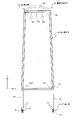
まず、図1を参照して、本発明の車両用休息具10の基本形態の構成について説明する。本実施形態に係る車両用休息具10は、休息具本体12と、第1係止部14、及び第2係止部16を基本として構成されている。休息具本体12は、使用状態において使用者50(図5参照)の下半身を支持するための要素である。具体的には、長方形の布地であれば良く、その長手方向長さ(図1におけるY軸方向の長さ)は一例として、後列シート40の座部42から前列シート30の背もたれ部32、特にショルダー部34(いずれも図4等参照)を繋ぐ程度の長さがあれば良く、幅方向長さ(図1におけるX軸方向の長さ)は、シート(例えば後列シート40)の座部42の幅と同等程度の長さがあれば良い。 [Basic form: configuration]
First, referring to FIG. 1, the configuration of the basic configuration of avehicle resting device 10 of the present invention will be described. The vehicle resting device 10 according to the present embodiment basically includes a resting device main body 12 , a first locking portion 14 and a second locking portion 16 . The rest device main body 12 is an element for supporting the lower half of the body of the user 50 (see FIG. 5) in use. Specifically, any rectangular cloth may be used, and its length in the longitudinal direction (the length in the Y-axis direction in FIG. 1) is, for example, from the seat portion 42 of the back row seat 40 to the backrest portion 32 of the front row seat 30, particularly The length in the width direction (the length in the X-axis direction in FIG. 1) is sufficient to connect the shoulder portions 34 (both see FIG. 4 and the like). It is sufficient if the length is about the same as the width of .
まず、図1を参照して、本発明の車両用休息具10の基本形態の構成について説明する。本実施形態に係る車両用休息具10は、休息具本体12と、第1係止部14、及び第2係止部16を基本として構成されている。休息具本体12は、使用状態において使用者50(図5参照)の下半身を支持するための要素である。具体的には、長方形の布地であれば良く、その長手方向長さ(図1におけるY軸方向の長さ)は一例として、後列シート40の座部42から前列シート30の背もたれ部32、特にショルダー部34(いずれも図4等参照)を繋ぐ程度の長さがあれば良く、幅方向長さ(図1におけるX軸方向の長さ)は、シート(例えば後列シート40)の座部42の幅と同等程度の長さがあれば良い。 [Basic form: configuration]
First, referring to FIG. 1, the configuration of the basic configuration of a
また、その構成素材としては、一般的な布地の他、帆布やターポリン、ベルト状部材を編み込んだもの、メッシュ素材、ネット素材等、種々のものを選択する事ができると共に、その部位によって素材を異ならせたり、組み合わせたりするようにしても良い。
In addition to general fabrics, it is possible to select various materials such as canvas, tarpaulin, woven belt-like members, mesh materials, net materials, etc., and the material can be selected depending on the part. They may be made different or combined.
実施形態に係る休息具本体12は、四辺を折り込んだり、補強部材を当てて縫製することで強度の向上を図るようにしている。また、後列シート40の座部42に係止される側となる一端12aと、前列シート30の背もたれ部32に係止されることとなる他端12bとを構成する辺にはそれぞれ、幅を縮めるようにタック12a1,12b1を設けるようにしている。タック12a1,12b1を設ける事により、休息具本体12に使用者50の下半身を載せた際、その荷重によりタック12a1,12b1が広がり、休息具本体12が下半身を包み込むような形状となる。これにより、支持状態を安定させることができるようになる。
The resting device main body 12 according to the embodiment is designed to improve strength by folding the four sides or by sewing with a reinforcing member applied. In addition, the sides forming the one end 12a to be engaged with the seat portion 42 of the back row seat 40 and the other end 12b to be engaged with the backrest portion 32 of the front row seat 30 each have a width. Tucks 12a1 and 12b1 are provided so as to shrink. By providing the tucks 12a1 and 12b1, when the lower body of the user 50 is placed on the resting device main body 12, the tucks 12a1 and 12b1 spread due to the load, and the resting device main body 12 has a shape that wraps the lower half of the body. This makes it possible to stabilize the supporting state.
なお、図1に示す形態では、一端12a側に設けるタック12a1の数に比べて他端12b側に設けるタック12b1の数を多くし、脚部先端側に、確実な包み込みが生じるように構成している。このため、平置き状態では、一端12a側の幅に比べて他端12b側の幅が狭くなっている。ここで、本実施形態における係止には、確実な固定、掛け止めのみならず、近接状態で支持されている状態等を含むものとする。
In the form shown in FIG. 1, the number of tucks 12b1 provided on the other end 12b side is greater than the number of tacks 12a1 provided on the one end 12a side, and the tip end side of the leg is securely wrapped. ing. Therefore, in the flat state, the width of the other end 12b side is narrower than the width of the one end 12a side. Here, locking in this embodiment includes not only secure fixing and latching, but also a state of being supported in a close proximity state.
第1係止部14は、休息具本体12の一端12a側に設けられ、休息具本体12の一端12aを後列シート40の座部42に係止するための要素である。具体的には、一端12aに接続された調整ベルト14aと、バックル14bとにより構成されている。実施形態に係るバックル14bは、後列シート40の座部42に備えられているIsofixアンカー(不図示)に係止可能なものであれば良い。このような構成とする事により、第1係止部14による係止を強固なものとすることができ、使用時の安全性を向上させることができる。また、バックル14bには、バックルコキが備えられ、調整ベルト14aを係止と長さ調整(係止位置の位置決め)が可能な構成とし、休息具本体12の一端12aとバ
ックル14bとの間の距離を容易に調節する事ができる構成されている。 Thefirst locking portion 14 is provided on the one end 12 a side of the resting device main body 12 and is an element for locking the one end 12 a of the resting device main body 12 to the seat portion 42 of the back row seat 40 . Specifically, it is composed of an adjustment belt 14a connected to one end 12a and a buckle 14b. The buckle 14b according to the embodiment may be any one that can be locked to an Isofix anchor (not shown) provided on the seat portion 42 of the rear row seat 40 . With such a configuration, the locking by the first locking portion 14 can be strengthened, and the safety during use can be improved. In addition, the buckle 14b is provided with a buckle joint, and the adjustment belt 14a is configured so that it can be locked and its length can be adjusted (positioning of the locking position), and the one end 12a of the resting device main body 12 and the buckle 14b It is configured so that the distance can be easily adjusted.
ックル14bとの間の距離を容易に調節する事ができる構成されている。 The
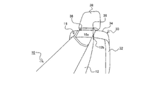
第2係止部16は、休息具本体12の他端12b側に設けられ、休息具本体12の他端12bを前列シート30の背もたれ部32に係止するための要素である。具体的には、他端12bに接続された係止ベルト16aにより構成されている。図1に示す係止ベルト16aは、ベルトの両端部をそれぞれ、休息具本体12の他端12bにおける幅方向端部に接続し、取手状の形態を成すように構成されている。このように構成された第2係止部16は、取手状の部分に前列シート30におけるヘッドレストポール36を通すことで、背もたれ部32に対する他端12bの係止を成す事ができる。
The second locking portion 16 is provided on the side of the other end 12b of the resting device main body 12 and is an element for locking the other end 12b of the resting device main body 12 to the backrest portion 32 of the front row seat 30 . Specifically, it is composed of a locking belt 16a connected to the other end 12b. The locking belt 16a shown in FIG. 1 is configured such that both ends of the belt are connected to the widthwise ends of the other end 12b of the resting device main body 12 to form a handle-like shape. The second locking portion 16 configured in this way can lock the other end 12b to the backrest portion 32 by passing the headrest pole 36 of the front row seat 30 through the handle-like portion.
[作用・効果]
上記のような基本構成を有する車両用休息具10は、次のようにして使用することができる。まず、図2に示すように、第2係止部16を前列シート30のヘッドレストポール36に掛けることで、休息具本体12の他端12bを前列シート30の背もたれ部32に係止する。ここで、休息具本体12における他端12bの高さは、第2係止部16を構成する係止ベルト16aの長さによって定める事ができる。このため、係止ベルト16aには、コキなどの長さ調整手段を設けるようにしても良い。なお、コキに加えてバックルを備え(いずれも不図示)、取手状の第2係止部16を開放可能な構成としても良い。バックルを備えて開放可能な構成とすれば、ヘッドレスト38の投影面が第2係止部16が構成する取手状の投影面より大きい場合でも、ヘッドレスト38を取り外す事無く係止することが可能となる。 [Action/effect]
Thevehicle rest device 10 having the basic configuration as described above can be used as follows. First, as shown in FIG. 2, the second locking portion 16 is hooked to the headrest pole 36 of the front row seat 30 to lock the other end 12b of the resting device main body 12 to the backrest portion 32 of the front row seat 30 . Here, the height of the other end 12b of the resting device main body 12 can be determined by the length of the locking belt 16a forming the second locking portion 16. As shown in FIG. For this reason, the locking belt 16a may be provided with a length adjusting means such as a foot. It should be noted that a buckle may be provided in addition to the grip (neither of which is shown) so that the handle-shaped second locking portion 16 can be opened. If the buckle is provided to enable the headrest to be opened, even if the projection surface of the headrest 38 is larger than the handle-shaped projection surface of the second locking portion 16, the headrest 38 can be locked without removing it. Become.
上記のような基本構成を有する車両用休息具10は、次のようにして使用することができる。まず、図2に示すように、第2係止部16を前列シート30のヘッドレストポール36に掛けることで、休息具本体12の他端12bを前列シート30の背もたれ部32に係止する。ここで、休息具本体12における他端12bの高さは、第2係止部16を構成する係止ベルト16aの長さによって定める事ができる。このため、係止ベルト16aには、コキなどの長さ調整手段を設けるようにしても良い。なお、コキに加えてバックルを備え(いずれも不図示)、取手状の第2係止部16を開放可能な構成としても良い。バックルを備えて開放可能な構成とすれば、ヘッドレスト38の投影面が第2係止部16が構成する取手状の投影面より大きい場合でも、ヘッドレスト38を取り外す事無く係止することが可能となる。 [Action/effect]
The
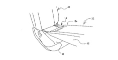
次に、図3に示すように、第1係止部14を後列シート40の座部42に設けられたIsofixアンカーに係止し、休息具本体12の一端12aを後列シート40の座部42に係止する。第1係止部14と第2係止部16による係止が完了すると、休息具本体12は図4に示すように、前列シート30の背もたれ部32と後列シート40の座部42に掛け渡された状態となる。ここで、休息具本体12の張り具合は、第1係止部14における調整ベルト14aの長さを変化させることで調節することができる。なお、本説明では、第2係止部16を係止した後、第1係止部14の係止を行うように説明しているが、第1係止部14を先に係止し、後に第2係止部16を係止するようにしても良く、使用にあたっては、係止の順序を限定するものでは無い。
Next, as shown in FIG. 3 , the first locking portion 14 is locked to the Isofix anchor provided on the seat portion 42 of the back row seat 40 , and the one end 12 a of the rest device body 12 is attached to the seat portion 42 of the back row seat 40 . to lock. When locking by the first locking portion 14 and the second locking portion 16 is completed, the resting device main body 12 spans the backrest portion 32 of the front row seat 30 and the seat portion 42 of the rear row seat 40 as shown in FIG. state. Here, the tension of the resting device main body 12 can be adjusted by changing the length of the adjustment belt 14a in the first engaging portion 14. As shown in FIG. In this description, the first locking portion 14 is locked after the second locking portion 16 is locked. The second locking portion 16 may be locked later, and the order of locking is not limited in use.
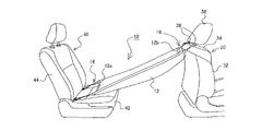
車両用休息具10をこのようにセットすることで、休息具本体12が使用者50の下半身を支持する事が可能となり、使用者50は足を伸ばしてリラックスする事ができるようになる。また、必要に応じて後列シート40の背もたれ部44をリクライニングすることで、図5に示すように、体全体を伸ばして横になる事も可能となる。
By setting the vehicle resting device 10 in this way, the resting device main body 12 can support the lower body of the user 50, and the user 50 can stretch his legs and relax. In addition, by reclining the backrest portion 44 of the rear row seat 40 as necessary, it is possible to stretch the entire body and lie down as shown in FIG.
このように、本実施形態に係る車両用休息具10によれば、少なくとも前列シート30と後列シート40(前列シート30が1列目であるか、2列目以降であるかは問わない)を有する車両であれば、シート形態や、シートの配置に制約無く使用する事ができる。また、第1係止部14を後列シート40に係止し、第2係止部16を前列シート30に係止するだけで使用する事ができるため、休息時の形態と移動時の形態とを素早く切り替える事も可能となる。さらに、使用者50の体重の大半は、後列シート40の座部42により支え、車両用休息具10自体は使用者50の下半身、特に脚部の重量のみを支えることとなるため、大人の使用にも耐える安全性を確保する事ができる。
As described above, according to the vehicle rest device 10 according to the present embodiment, at least the front row seat 30 and the rear row seat 40 (regardless of whether the front row seat 30 is the first row or the second row or later) are provided. If it is a vehicle that has it, it can be used without restrictions on the seat configuration and seat arrangement. In addition, since the first engaging portion 14 can be engaged with the rear seat 40 and the second engaging portion 16 can be engaged with the front seat 30, the seat can be used. can be switched quickly. Furthermore, most of the weight of the user 50 is supported by the seat portion 42 of the back row seat 40, and the vehicle resting device 10 itself supports only the weight of the lower body of the user 50, particularly the legs, so that it is suitable for use by adults. It is possible to ensure safety that can withstand even
[変形例]
上記実施形態では、休息具本体12に関して、一端12aと他端12bにタック12a1,12b1を設ける旨記載した。しかしながら、一端12aと他端12bには、タック12a1,12b1に変えてギャザーを設けるようにしても良い。このような構成とした
場合であっても、休息具本体12により支持部を包み込むといった作用を得る事ができるからである。 [Modification]
In the above-described embodiment, it is described that the tucks 12a1 and 12b1 are provided at the oneend 12a and the other end 12b of the resting device main body 12. As shown in FIG. However, the one end 12a and the other end 12b may be provided with gathers instead of the tucks 12a1 and 12b1. This is because even with such a configuration, it is possible to obtain the effect of wrapping the supporting portion with the resting device main body 12 .
上記実施形態では、休息具本体12に関して、一端12aと他端12bにタック12a1,12b1を設ける旨記載した。しかしながら、一端12aと他端12bには、タック12a1,12b1に変えてギャザーを設けるようにしても良い。このような構成とした
場合であっても、休息具本体12により支持部を包み込むといった作用を得る事ができるからである。 [Modification]
In the above-described embodiment, it is described that the tucks 12a1 and 12b1 are provided at the one
また、上記実施形態では、第2係止部16の形態は取手状である旨記載した。しかしながら、前列シート30のヘッドレストポール36に係止することができる形態であれば、これに限定するものでは無い。例えば図6に示すように、係止ベルト16aとフック16bにより構成されていたり、フック16bに変えてカラビナ(不図示)が備えられているようなものであっても良い。また、第2係止部16の係止先についても、ヘッドレストポール36に限定されるものではない。例えば前列シート30にIsofixアンカーが存在する場合には、第1係止部14と同様に、調整ベルトとバックルにより固定し、前列シート30における背もたれ部32のショルダー部34を経由して、休息具本体12における他端12bの係止を図るようにすれば良い。
Also, in the above embodiment, it is described that the second locking portion 16 is shaped like a handle. However, the configuration is not limited to this as long as it can be engaged with the headrest pole 36 of the front row seat 30 . For example, as shown in FIG. 6, it may consist of a locking belt 16a and a hook 16b, or a carabiner (not shown) may be provided in place of the hook 16b. Further, the locking destination of the second locking portion 16 is not limited to the headrest pole 36 either. For example, if there is an Isofix anchor on the front row seat 30, it is fixed with an adjustment belt and a buckle in the same manner as the first locking portion 14, and the rest tool is attached via the shoulder portion 34 of the backrest portion 32 of the front row seat 30. The other end 12b of the main body 12 may be engaged.
また、第1係止部14と第2係止部16の係止先に関しては、必ずしも直近の前後関係にあるシートとする必要は無い。例えば、前列シート30を助手席とし、後列シート40を運転席の後方に位置するシートとして、第1係止部14と第2係止部16を係止するようにしても良い。
In addition, it is not necessary for the first locking portion 14 and the second locking portion 16 to be locked to a seat that is in the immediate front-to-back relationship. For example, the first locking portion 14 and the second locking portion 16 may be locked by using the front row seat 30 as a passenger seat and the rear row seat 40 as a seat located behind the driver's seat.
[応用形態1]
また、上記実施形態に係る車両用休息具10は、一人用のサイズとしているが、二人用のサイズとする事もできる。車両用休息具10を二人用とする場合、図7に示すように、休息具本体12は、2つのシートを跨ぐ幅(図7におけるX軸方向長さ)を有し、第1係止部14は、各シートに設けられたIsofixアンカーに係止可能な数(例えば4つ)だけ設けるようにする。また、第2係止部16を2つの前列シートそれぞれのヘッドレストポール36(36a,36b)に係止する場合には、図7に示すように、各シートのヘッドレストポール36a,36bに対して係止ベルト16aの一部が交差する形態、いわゆるたすき掛けとなるようにして係止可能な構成とすると良い。このような係止形態とすることで、休息具本体12の幅方向(X軸方向)中心部の沈み込みを抑える事ができ、支持状態の安定化を図ることができる。 [Application 1]
Further, although thevehicle resting device 10 according to the above embodiment is sized for one person, it may be sized for two people. When the vehicle resting device 10 is for two people, as shown in FIG. 7, the resting device main body 12 has a width spanning two seats (the length in the X-axis direction in FIG. The portions 14 are provided in a number (for example, four) that can be engaged with the Isofix anchors provided on each seat. When the second engaging portion 16 is engaged with the headrest poles 36 (36a, 36b) of the two front seats, as shown in FIG. It is preferable that the stop belt 16a has a configuration in which a part of the stop belt 16a intersects, that is, a structure that can be locked so as to form a so-called crossing. By adopting such a locking form, it is possible to suppress the sinking of the central portion of the resting device main body 12 in the width direction (X-axis direction), thereby stabilizing the supporting state.
また、上記実施形態に係る車両用休息具10は、一人用のサイズとしているが、二人用のサイズとする事もできる。車両用休息具10を二人用とする場合、図7に示すように、休息具本体12は、2つのシートを跨ぐ幅(図7におけるX軸方向長さ)を有し、第1係止部14は、各シートに設けられたIsofixアンカーに係止可能な数(例えば4つ)だけ設けるようにする。また、第2係止部16を2つの前列シートそれぞれのヘッドレストポール36(36a,36b)に係止する場合には、図7に示すように、各シートのヘッドレストポール36a,36bに対して係止ベルト16aの一部が交差する形態、いわゆるたすき掛けとなるようにして係止可能な構成とすると良い。このような係止形態とすることで、休息具本体12の幅方向(X軸方向)中心部の沈み込みを抑える事ができ、支持状態の安定化を図ることができる。 [Application 1]
Further, although the
[応用形態2]
また、上記実施形態では、車両用休息具10の取付形態として、車両に据付けられている後列シート40の座部42に一端を係止し、同じく前列シート30の背もたれ部32に他端を係止する旨記載した。しかしながら、車両用休息具10の一端の係止は、必ずしも車両に据付けられたシートとしなくても良い。 [Application form 2]
In the above-described embodiment, thevehicle rest device 10 is mounted in such a manner that one end thereof is engaged with the seat portion 42 of the rear row seat 40 installed in the vehicle, and the other end thereof is engaged with the backrest portion 32 of the front row seat 30. stated to stop. However, one end of the vehicle resting device 10 does not necessarily have to be a seat installed in the vehicle.
また、上記実施形態では、車両用休息具10の取付形態として、車両に据付けられている後列シート40の座部42に一端を係止し、同じく前列シート30の背もたれ部32に他端を係止する旨記載した。しかしながら、車両用休息具10の一端の係止は、必ずしも車両に据付けられたシートとしなくても良い。 [Application form 2]
In the above-described embodiment, the
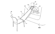
例えば図8に示すように車両の外部(例えば車両後方)に、使用者50が着座可能なシート46を配置し、この配置したシート46の座部に第1係止部14を介して休息具本体12の一端12aを係止し、他端12bを車両のシート(例えば後部座席にあたるシート(後列シート40))の背もたれ部44に係止されるようにすれば良い。なお、このような使用形態を採る場合、第1係止部14の構成を図9に示すような係止ベルトにより構成した輪やフック(不図示)などとすると良い。
For example, as shown in FIG. 8 , a seat 46 on which a user 50 can sit is arranged outside the vehicle (for example, behind the vehicle), and a resting device is attached to the seat portion of the arranged seat 46 via the first engaging portion 14 . One end 12a of the main body 12 may be locked, and the other end 12b may be locked to the backrest portion 44 of a vehicle seat (for example, a seat corresponding to a rear seat (rear row seat 40)). In the case of adopting such a mode of use, it is preferable that the structure of the first locking portion 14 is a ring or a hook (not shown) made up of a locking belt as shown in FIG.
[応用形態3]
上記実施形態ではいずれも、車両用休息具10は、休息具本体12を使用者50の前方に配置することにより、使用者50の下半身を支持する構成とする旨説明した。しかしながら、本発明に係る車両用休息具10は、使用者50の上半身を支持する構成とすることもできる。具体的には図10に示すように、シート(例えば後列シート40)の座部42に第1係止部14(図10には不図示)を介して休息具本体12の一端12aを係止可能な構成とする。そして、休息具本体12の他端12bに設けた第2係止部16は、使用者
50が着座しているシート(図10に示す例では後列シート40)に対応して設けられているアシストグリップ48に係止可能な構成とする。 [Application 3]
In each of the above-described embodiments, thevehicle rest device 10 is configured to support the lower body of the user 50 by disposing the rest device main body 12 in front of the user 50 . However, the vehicle rest device 10 according to the present invention can also be configured to support the upper body of the user 50 . Specifically, as shown in FIG. 10, one end 12a of the resting device main body 12 is locked to the seat portion 42 of the seat (for example, the back row seat 40) via the first locking portion 14 (not shown in FIG. 10). possible configuration. The second locking portion 16 provided at the other end 12b of the resting device main body 12 is provided in correspondence with the seat on which the user 50 is seated (rear row seat 40 in the example shown in FIG. 10). It is configured to be lockable with the grip 48 .
上記実施形態ではいずれも、車両用休息具10は、休息具本体12を使用者50の前方に配置することにより、使用者50の下半身を支持する構成とする旨説明した。しかしながら、本発明に係る車両用休息具10は、使用者50の上半身を支持する構成とすることもできる。具体的には図10に示すように、シート(例えば後列シート40)の座部42に第1係止部14(図10には不図示)を介して休息具本体12の一端12aを係止可能な構成とする。そして、休息具本体12の他端12bに設けた第2係止部16は、使用者
50が着座しているシート(図10に示す例では後列シート40)に対応して設けられているアシストグリップ48に係止可能な構成とする。 [Application 3]
In each of the above-described embodiments, the
アシストグリップ48は主に、車両の内側壁天井側に位置している。このため、休息具本体12の他端12bに設ける第2係止部16は、休息具本体12の幅方向端部近傍に備えるようにすることが望ましい。第2係止部16の基端部の配置幅を広げることで、休息具本体12における使用者50の支持領域の幅を広げることができるからである。
The assist grip 48 is mainly located on the inner wall ceiling side of the vehicle. For this reason, it is desirable that the second engaging portion 16 provided at the other end 12b of the resting device main body 12 is provided in the vicinity of the width direction end of the resting device main body 12 . This is because the width of the support area for the user 50 in the resting device main body 12 can be widened by widening the arrangement width of the base end portion of the second locking portion 16 .
このような構成の車両用休息具10を構成する休息具本体12を使用者50が着座するシート(後列シート40)の背もたれ部44側、すなわち使用者50の後方に配置することで、使用者50の上半身を支持することが可能となる。
By arranging the resting device main body 12 constituting the vehicle resting device 10 having such a configuration on the backrest portion 44 side of the seat (rear row seat 40) on which the user 50 sits, that is, behind the user 50, the user can It is possible to support the upper body of 50.
このような構成、及び使用形態の車両用休息具10であっても、使用者50の体重の大半は、使用者50が着座しているシートの座部(後列シート40の座部42)により支え、車両用休息具10自体は使用者50の上半身、特に頭部と胸部の重量のみを支えることとなるため、大人の使用にも耐える安全性を確保する事ができる。
Even with such a configuration and usage pattern of the vehicle rest device 10, most of the weight of the user 50 is due to the seat portion of the seat on which the user 50 is seated (the seat portion 42 of the back row seat 40). Since the vehicle resting device 10 itself supports only the weight of the upper half of the body of the user 50, especially the head and chest, it is possible to ensure safety even when used by adults.
[応用形態4]
また、本発明に係る車両用休息具は、上述した使用者50の下半身を支持するための休息具本体12(第1休息具本体)と、使用者50の上半身を支持するための休息具本体12(第2休息具本体)とを組み合わせたものとしても良い。このような構成の車両用休息具では、第1休息具本体の一端と、第2休息具本体の一端をいずれも車両のIsofixアンカーに係止する場合には、両者に共通な第1係止部14を設けるようにすると良い。その他の構成については、それぞれ上述した車両用休息具10の構成に倣えば良い。 [Application 4]
Further, the vehicle resting device according to the present invention includes the resting device main body 12 (first resting device main body) for supporting the lower body of theuser 50 and the resting device main body for supporting the upper body of the user 50 . 12 (second rest device body) may be combined. In the vehicle resting device having such a configuration, when both one end of the first resting device main body and one end of the second resting device main body are locked to the Isofix anchor of the vehicle, the first locking mechanism common to both is used. A portion 14 is preferably provided. Other configurations may follow the configuration of the vehicle rest device 10 described above.
また、本発明に係る車両用休息具は、上述した使用者50の下半身を支持するための休息具本体12(第1休息具本体)と、使用者50の上半身を支持するための休息具本体12(第2休息具本体)とを組み合わせたものとしても良い。このような構成の車両用休息具では、第1休息具本体の一端と、第2休息具本体の一端をいずれも車両のIsofixアンカーに係止する場合には、両者に共通な第1係止部14を設けるようにすると良い。その他の構成については、それぞれ上述した車両用休息具10の構成に倣えば良い。 [Application 4]
Further, the vehicle resting device according to the present invention includes the resting device main body 12 (first resting device main body) for supporting the lower body of the
車両用休息具10をこのような組み合わせによる構成とした場合でも、使用者50の体重の大半は、着座しているシートの座部により支えるため、第2係止部16を係止する車内構造物(例えばヘッドレストポール36や、アシストグリップ48)に過度な負荷がかかる虞がない。
Even when the vehicle rest device 10 is configured by such a combination, most of the weight of the user 50 is supported by the seat portion of the seat on which the user 50 is seated. There is no concern that an excessive load is applied to objects (eg, headrest pole 36 and assist grip 48).
本発明に係る休息具は車両用休息具10として、使用対象を車両としているが、前列シート30と後列シート40が存在すれば、様々なタイプの車両、又は車両以外のシートにも適用することができる。
The resting device according to the present invention is used as a vehicle resting device 10 for a vehicle, but if there are a front row seat 30 and a rear row seat 40, it can be applied to various types of vehicles or seats other than vehicles. can be done.
10………車両用休息具、12………休息具本体、12a………一端、12a1………タック、12b………他端、12b1………タック、14………第1係止部、14a………調整ベルト、14b………バックル、16………第2係止部、16a………係止ベルト、16b………フック、30………前列シート、32………背もたれ部、34………ショルダー部、36(36a,36b)………ヘッドレストポール、38………ヘッドレスト、40………後列シート、42………座部、44………背もたれ部、46………シート、48………アシストグリップ、50………使用者。
10…………Vehicle resting device 12……Resting device main body 12a……One end 12a1……Tuck 12b……Other end 12b1……Tuck 14……First locking Part 14a Adjusting belt 14b Buckle 16 Second locking part 16a Locking belt 16b Hook 30 Front row seat 32 Backrest portion 34 Shoulder portion 36 (36a, 36b) Headrest pole 38 Headrest 40 Back row seat 42 Seat portion 44 Backrest portion 46 …………Seat, 48……Assist grip, 50……User.
Claims (8)
- 少なくとも使用者の体の一部を支持する休息具本体と、
前記休息具本体の一端に設けられ、前記使用者が着座するシートの座部に係止する第1係止部と、
前記休息具本体の他端に設けられ、前記座部よりも高い位置に設けられた車内構造物に係止される第2係止部と、を備えることを特徴とする車両用休息具。 a resting device main body supporting at least a part of a user's body;
a first engaging portion provided at one end of the body of the resting device and engaged with a seat portion of the seat on which the user sits;
a second locking portion provided at the other end of the body of the resting device and engaged with an in-vehicle structure provided at a position higher than the seat portion. - 前記休息具本体は、前記使用者の前方に配置する構成とし、
前記第2係止部は、車両に固定されたシートの背もたれ部に係止される構成としたことを特徴とする請求項1に記載の車両用休息具。 The body of the resting equipment is configured to be arranged in front of the user,
2. The vehicle resting device according to claim 1, wherein the second locking portion is configured to be locked to a backrest portion of a seat fixed to the vehicle. - 前記休息具本体は、前記使用者の後方に配置する構成とし、
前記第2係止部は、前記シートに対応して設けられているアシストグリップに係止される構成としたことを特徴とする請求項1に記載の車両用休息具。 The body of the resting equipment is configured to be arranged behind the user,
2. The vehicle resting device according to claim 1, wherein the second locking portion is configured to be locked to an assist grip provided corresponding to the seat. - 前記休息具本体は、2つのシート座部を跨ぐ幅を有することを特徴とする請求項1乃至3のいずれか1項に記載の車両用休息具。 The vehicle resting equipment according to any one of claims 1 to 3, wherein the resting equipment main body has a width spanning two seat portions.
- 使用者の前方に配置する第1休息具本体と、
前記使用者の後方に配置する第2休息具本体と、
前記第1休息具本体の一端と、前記第2休息具本体の一端に設けられ、前記使用者が着座するシートの座部に係止する第1係止部と、
前記第1休息具本体の他端に設けられ、前記シートよりも前列に位置するシートの背もたれ部に係止される第1休息具第2係止部と、
前記第2休息具本体の他端に設けられ、前記シートに対応して設けられているアシストグリップに係止される第2休息具第2係止部と、を備えることを特徴とする車両用休息具。 a first resting equipment main body arranged in front of the user;
a second resting equipment main body arranged behind the user;
one end of the first resting device main body, a first engaging portion provided at one end of the second resting device main body and engaged with a seat portion of the seat on which the user sits;
a first resting device second locking portion provided at the other end of the first resting device main body and locked to a backrest portion of a seat positioned in a front row relative to the seat;
a second resting device second engaging portion provided at the other end of the second resting device main body and engaged with an assist grip provided corresponding to the seat; resting gear. - 前記第1休息具本体及び/または前記第2休息具本体は、2つのシート座部を跨ぐ幅を有することを特徴とする請求項5に記載の車両用休息具。 The vehicle resting equipment according to claim 5, wherein the first resting equipment main body and/or the second resting equipment main body have a width spanning two seat portions.
- 前記第1係止部には、Isofixアンカーに係止可能なバックルが備えられていることを特徴とする請求項1乃至6のいずれか1項に記載の車両用休息具。 The vehicle resting device according to any one of claims 1 to 6, wherein the first locking portion is provided with a buckle that can be locked to an Isofix anchor.
- 前記一端と前記他端には、それぞれ幅方向に対するタックが設けられていることを特徴とする請求項1乃至7のいずれか1項に記載の車両用休息具。 The vehicle resting device according to any one of claims 1 to 7, characterized in that the one end and the other end are each provided with tucks in the width direction.
Applications Claiming Priority (2)
| Application Number | Priority Date | Filing Date | Title |
|---|---|---|---|
| JP2021086431A JP7317892B2 (en) | 2021-05-21 | 2021-05-21 | vehicle rest |
| JP2021-086431 | 2021-05-21 |
Publications (1)
| Publication Number | Publication Date |
|---|---|
| WO2022244442A1 true WO2022244442A1 (en) | 2022-11-24 |
Family
ID=84141163
Family Applications (1)
| Application Number | Title | Priority Date | Filing Date |
|---|---|---|---|
| PCT/JP2022/012530 WO2022244442A1 (en) | 2021-05-21 | 2022-03-18 | Vehicle resting apparatus |
Country Status (2)
| Country | Link |
|---|---|
| JP (1) | JP7317892B2 (en) |
| WO (1) | WO2022244442A1 (en) |
Citations (7)
| Publication number | Priority date | Publication date | Assignee | Title |
|---|---|---|---|---|
| US2601488A (en) * | 1947-10-03 | 1952-06-24 | Paul E Allen | Auto bed |
| FR2076481A5 (en) * | 1970-01-16 | 1971-10-15 | Menil Claude | |
| JPS592638U (en) * | 1982-06-30 | 1984-01-09 | いすゞ自動車株式会社 | Seat with hammock |
| JPS6045143U (en) * | 1983-09-01 | 1985-03-29 | トヨタ車体株式会社 | Folding bed for vehicle |
| JPS63168134U (en) * | 1987-04-22 | 1988-11-01 | ||
| JPH1143099A (en) * | 1994-12-28 | 1999-02-16 | Kazuko Adachi | Hammock type foot hanger for aircraft cabin |
| US20130200663A1 (en) * | 2012-02-02 | 2013-08-08 | Monti Marsters | Travel Foot Rest |
Family Cites Families (5)
| Publication number | Priority date | Publication date | Assignee | Title |
|---|---|---|---|---|
| JPS5864322U (en) * | 1981-10-24 | 1983-04-30 | 高橋 良一 | Hanging belt for transporting heavy objects |
| JPS6131163U (en) * | 1984-07-30 | 1986-02-25 | 悦三 阪口 | car seat cover |
| JP2000126250A (en) | 1998-10-23 | 2000-05-09 | Mikuni Corp | Suspender for caring lift |
| JP2009241814A (en) | 2008-03-31 | 2009-10-22 | Autech Japan Inc | Occupant fixing belt of vehicular seat |
| JP5444575B1 (en) | 2012-09-12 | 2014-03-19 | 有限会社青葉テクノソリューションズ | Human body lifting harness |
-
2021
- 2021-05-21 JP JP2021086431A patent/JP7317892B2/en active Active
-
2022
- 2022-03-18 WO PCT/JP2022/012530 patent/WO2022244442A1/en unknown
Patent Citations (7)
| Publication number | Priority date | Publication date | Assignee | Title |
|---|---|---|---|---|
| US2601488A (en) * | 1947-10-03 | 1952-06-24 | Paul E Allen | Auto bed |
| FR2076481A5 (en) * | 1970-01-16 | 1971-10-15 | Menil Claude | |
| JPS592638U (en) * | 1982-06-30 | 1984-01-09 | いすゞ自動車株式会社 | Seat with hammock |
| JPS6045143U (en) * | 1983-09-01 | 1985-03-29 | トヨタ車体株式会社 | Folding bed for vehicle |
| JPS63168134U (en) * | 1987-04-22 | 1988-11-01 | ||
| JPH1143099A (en) * | 1994-12-28 | 1999-02-16 | Kazuko Adachi | Hammock type foot hanger for aircraft cabin |
| US20130200663A1 (en) * | 2012-02-02 | 2013-08-08 | Monti Marsters | Travel Foot Rest |
Also Published As
| Publication number | Publication date |
|---|---|
| JP2022179152A (en) | 2022-12-02 |
| JP7317892B2 (en) | 2023-07-31 |
Similar Documents
| Publication | Publication Date | Title |
|---|---|---|
| US7431324B2 (en) | Body receptacle for a wheeled frame | |
| JP3007149B2 (en) | Expandable and stowable infant vehicle seat | |
| JP6762862B2 (en) | Seatbelt wiring structure and vehicle seats equipped with it | |
| US8657371B2 (en) | Car seat | |
| JPH07251661A (en) | Car seat provided with integrated seat for child | |
| JP2020028410A (en) | vehicle | |
| WO2022244442A1 (en) | Vehicle resting apparatus | |
| JP4452231B2 (en) | Pet seat cover | |
| JP7313798B2 (en) | vehicle seat | |
| US11491900B2 (en) | Hanging type seat | |
| JP2008265388A (en) | Vehicular auxiliary seat device | |
| JP3972974B2 (en) | Automotive seat | |
| JP3527545B2 (en) | Lumbar support structure for folding seats for automobiles | |
| JPH0350051A (en) | Automotive guard for preventing passenger from falling | |
| JP7193703B2 (en) | vehicle seat | |
| JP2004352032A (en) | Vehicular mattress | |
| JP7048876B2 (en) | Seat | |
| JP2010233941A (en) | Seat belt holder | |
| JP2002087124A (en) | Child seat | |
| JPH0357222Y2 (en) | ||
| JP5809427B2 (en) | Vehicle seat | |
| JPH0727934U (en) | Rear seat slide lock structure | |
| JP5872934B2 (en) | Vehicle seat | |
| JP2004065559A (en) | Seat structure for vehicle | |
| JP2024009719A (en) | Handrest device |
Legal Events
| Date | Code | Title | Description |
|---|---|---|---|
| 121 | Ep: the epo has been informed by wipo that ep was designated in this application |
Ref document number: 22804360 Country of ref document: EP Kind code of ref document: A1 |
|
| NENP | Non-entry into the national phase |
Ref country code: DE |