WO2022239487A1 - 風力発電装置 - Google Patents
風力発電装置 Download PDFInfo
- Publication number
- WO2022239487A1 WO2022239487A1 PCT/JP2022/013182 JP2022013182W WO2022239487A1 WO 2022239487 A1 WO2022239487 A1 WO 2022239487A1 JP 2022013182 W JP2022013182 W JP 2022013182W WO 2022239487 A1 WO2022239487 A1 WO 2022239487A1
- Authority
- WO
- WIPO (PCT)
- Prior art keywords
- electrodes
- electrode
- rotating body
- circumferential direction
- wind turbine
- Prior art date
- Legal status (The legal status is an assumption and is not a legal conclusion. Google has not performed a legal analysis and makes no representation as to the accuracy of the status listed.)
- Ceased
Links
Images






Classifications
-
- F—MECHANICAL ENGINEERING; LIGHTING; HEATING; WEAPONS; BLASTING
- F03—MACHINES OR ENGINES FOR LIQUIDS; WIND, SPRING, OR WEIGHT MOTORS; PRODUCING MECHANICAL POWER OR A REACTIVE PROPULSIVE THRUST, NOT OTHERWISE PROVIDED FOR
- F03D—WIND MOTORS
- F03D3/00—Wind motors with rotation axis substantially perpendicular to the air flow entering the rotor
- F03D3/06—Rotors
-
- Y—GENERAL TAGGING OF NEW TECHNOLOGICAL DEVELOPMENTS; GENERAL TAGGING OF CROSS-SECTIONAL TECHNOLOGIES SPANNING OVER SEVERAL SECTIONS OF THE IPC; TECHNICAL SUBJECTS COVERED BY FORMER USPC CROSS-REFERENCE ART COLLECTIONS [XRACs] AND DIGESTS
- Y02—TECHNOLOGIES OR APPLICATIONS FOR MITIGATION OR ADAPTATION AGAINST CLIMATE CHANGE
- Y02E—REDUCTION OF GREENHOUSE GAS [GHG] EMISSIONS, RELATED TO ENERGY GENERATION, TRANSMISSION OR DISTRIBUTION
- Y02E10/00—Energy generation through renewable energy sources
- Y02E10/70—Wind energy
- Y02E10/74—Wind turbines with rotation axis perpendicular to the wind direction
Definitions
- This invention relates to a wind turbine generator.
- Patent Document 1 Japanese Patent Application Laid-Open No. 2021-32239
- An object of the present invention is to provide a wind turbine generator capable of reducing noise.
- a wind power generator includes a support shaft, a rotor supported by the support shaft so as to be rotatable about a central axis of the support shaft, a rotating body made of a dielectric, and the rotating body. a plurality of electrodes arranged on the surface of the body at intervals along the circumferential direction around the central axis; and a power supply for applying a predetermined voltage to each electrode of the plurality of electrodes at predetermined time intervals. , and a generator coupled to the rotating body.
- FIG. 1 is a perspective view of a wind turbine generator according to a first embodiment of the present invention
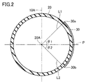
- FIG. It is a figure which shows roughly the cross section of the rotating body in a wind turbine generator.
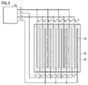
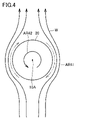
- FIG. 4 is a diagram schematically showing the relationship between electrodes and a voltage applying section; It is a figure for demonstrating the mechanism by which a rotating body rotates. It is a figure which shows the modification of a rotating body. It is a figure which shows the modification of a rotating body.
- 1 is a diagram schematically showing a wind turbine generator group consisting of a plurality of wind turbine generators; FIG. FIG.
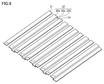
- FIG. 6 is a partially enlarged view of a rotating body and electrodes in a wind power generator according to a second embodiment of the present invention
- 9 is a perspective view of the electrode shown in FIG. 8
- FIG. 9 is a cross-sectional view taken along line XX in FIG. 8
- It is a sectional view showing a modification of the 2nd electrode roughly.
- FIG. 1 is a perspective view of a wind turbine generator according to a first embodiment of the invention.
- the wind turbine generator 1 includes a support shaft 10 , a rotor 20 , a plurality of electrodes 30 , a coating layer 40 , a power source 50 and a generator 60 .
- This wind power generator 1 does not have blades, unlike so-called horizontal or vertical axis wind power generators.
- the up-down direction in FIG. 1 is demonstrated as a perpendicular direction.
- the installation posture of the wind turbine generator 1 is not limited to the posture shown in FIG. Note that FIG. 1 is a schematic diagram, and the dimensions and ratios of each member, the spacing between the electrodes 30, and the like are different from the actual device. This also applies to other drawings.
- the support shaft 10 is, for example, cylindrical.
- the support shaft 10 is installed on an installation surface such as the ground.
- the posture of the support shaft 10 with respect to the installation surface is not particularly limited.
- the rotating body 20 is supported by the support shaft 10 so as to be rotatable around the central axis 10A of the support shaft 10.
- Rotating body 20 is made of a dielectric.
- the rotating body 20 is made of resin, a metal member covered with an insulating coating, or the like.
- Rotating body 20 is preferably made of fiber-reinforced plastic.
- the rotor 20 is hollow. In this embodiment, the rotor 20 is configured as a hollow sphere.
- the diameter of the rotating body 20 is, for example, about 1 m to 5 m. However, the size of the rotating body 20 can be set arbitrarily.
- a plurality of electrodes 30 are provided on the surface of the rotating body 20 so as to be spaced apart along the circumferential direction around the central axis 10A. It is preferable that the plurality of electrodes 30 be arranged on the surface of the rotating body 20 at equal intervals over the entire circumferential direction. However, a region in which no electrode 30 is provided (a region in which the electrode 30 is missing) may be provided on a part of the surface of the rotating body 20, and even if there are places where the intervals between the electrodes 30 in the circumferential direction are different. good. As shown in FIG. 2, each electrode 30 has a shape extending along a portion where a plane including the central axis 10A and the surface of the rotating body 20 intersect.
- An angle ⁇ 1 between a plane P perpendicular to the central axis 10A and passing through the center 20A of the rotor 20 and a straight line L1 connecting the center 20A and the upper end 30a of the electrode 30 is set to about 45 degrees. is preferred.
- the angle ⁇ 2 between the plane P and the straight line L2 connecting the center 20A and the lower end 30b of the electrode 30 is preferably set to about 45 degrees.
- the interval between the electrodes 30 adjacent to each other is in the range of 1.7 ⁇ m to 90 ⁇ m, for example.
- the width of each electrode 30 (dimension of each electrode 30 in the circumferential direction) ranges from 20 ⁇ m to 100 ⁇ m, for example.
- the spacing between the electrodes 30 and the width of the electrodes 30 are determined in consideration of efficiency and ease of manufacture.
- the width of the electrode 30 need not be uniform, and portions with different widths may be provided according to the shape of the surface of the rotating body 20 .
- the width of each electrode 30 is set from the middle portion of each electrode 30 to the upper end portion of each electrode 30 in the vertical direction. and may be made thinner as it approaches the lower end. Note that FIG. 2 shows the rotating body 20 and one electrode 30 out of the plurality of electrodes 30 .
- the coating layer 40 covers the entire surface of the rotor 20 including the surfaces of the electrodes 30 .
- the coating layer 40 is made of an insulating material such as resin or silicate glass.
- the coating layer 40 is preferably formed thin.
- the coating layer 40 is preferably made of a colored material so that the electrodes 30 cannot be visually recognized from the outside. With this configuration, oxidation and sulfurization of the electrode 30 are suppressed, and stable characteristics are maintained over a long period of time.
- the coating layer 40 may cover only the electrodes 30 instead of the entire surface of the rotor 20 .
- the power supply 50 applies a predetermined voltage to each electrode 30 at predetermined time intervals.
- the power supply 50 applies a voltage to each electrode 30 so that an airflow is formed on the surface of the rotating body 20 along the circumferential direction by an electric field gradient force (dielectric gradient force).
- the method of applying this voltage that is, the method of forming an airflow along the direction in which the plurality of electrodes 30 are arranged (method of conveying the gas) is the same as the principle described in Japanese Patent No. 5633373 .
- the plurality of electrodes 30 are commonly connected, for example, every four electrodes in the order of their arrangement, and are respectively connected to the output terminals of the power source 50, and the power source 50 changes over time.
- the pulse voltage has a value in the range of 330 V to 950 V, and the pulse rise time is 1 ⁇ s or less.
- the strength of the airflow AR41 can be adjusted by the magnitude of the voltage and the period of the voltage.
- FIG. 3 shows linear electrodes arranged on a plane. This corresponds to an enlarged part of the rotating body 20 and the electrode 30 in this embodiment. Considering the size of the rotating body 20, the width of the electrode 30, and the spacing between a pair of electrodes 30 adjacent to each other, the rotating body 20 with respect to several to ten-odd electrodes 30 can be regarded as a substantially flat surface. For the sake of convenience, it is shown in this way.
- the electrodes 30 corresponding to the first to fourth phases are indicated by E 1 (j) to E 4 (j) , respectively.
- (j) is the period number of the four-phase repetition period.
- the number of electrodes 30 in one set and the number of pulse voltage phases are not limited to 4, and can be set to any integer n.
- the output terminal of the power supply is connected to the electrode through the capacitor, but the capacitor may not be interposed. The connection direction from the output terminal of the power supply is not limited to that shown in FIG.
- the generator 60 is connected to the rotating body 20.
- the generator 60 generates electric power by rotating the rotating body 20 .
- the generator 60 has magnets 62 and a stator 64 .
- the magnet 62 is fixed to the inner surface of the rotating body 20 so as to rotate integrally with the rotating body 20.
- the magnet 62 is fixed to the rotating body 20 directly or indirectly via another member.
- the stator 64 is surrounded by magnets 62 .
- the stator 64 is fixed directly to the support shaft 10 or indirectly via another member.
- the power supply 50 applies a voltage to each electrode 30 in the manner described above. As a result, an airflow AR41 that flows in the circumferential direction on the surface of the rotating body 20 is formed. In addition, in FIG. 4, the airflow AR41 is indicated by a chain double-dashed line. In addition, since the pulse voltage does not cause an actual current to flow, the power consumption is small.
- the rotating body 20 rotates about the central axis 10A in the direction AR42 opposite to the direction of the airflow AR41.
- the wind power generator 1 in this embodiment does not have blades that are provided in horizontal or vertical axis wind power generators, so noise is reduced. Furthermore, since the sense of fear given to people by the rotation of the blades is substantially eliminated, the wind turbine generator 1 can be installed in urban areas and the like.
- the power supply 50 adjusts the magnitude and period of the voltage applied to each electrode 30 based on the wind speed of the wind W striking the rotor 20 .
- the wind speed of the wind W striking the rotor 20 is detected by a wind speed sensor provided on the support shaft 10 or the like. Alternatively, it is possible to detect the wind force by the number of revolutions per minute of the rotating body 20 itself.
- the power supply 50 adjusts the magnitude and period of the voltage applied to each electrode 30 so that the number of revolutions of the rotating body 20 does not exceed a specified number of revolutions.
- the power supply 50 stops applying voltage to each electrode 30 .
- the body of revolution 20 may be composed of an oblate sphere obtained by rotating an ellipse with its short axis as the rotation axis.
- the rotor 20 is supported by the support shaft 10 so that its rotation axis (minor axis) coincides with the central axis 10A.
- the body of revolution 20 may be composed of an elongated sphere obtained by rotating an ellipse with its long axis as the axis of rotation.
- the rotating body 20 may be formed in a cylindrical shape.
- the wind turbine generator 1 having such a shape is extremely low-noise compared to a type in which a propeller or a windmill rotates, and at the same time, does not give people a sense of fear of the rotating body.
- There is a sense of wonder in terms of design and as shown in FIG. 7, when a plurality of wind power generators 1 are arranged in a forest with variations in size, height, and shape, they can function as a monument.
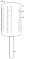
- the surface of the rotating body 20 may be plain, or may be provided with a display portion 20D for characters, advertisement designs, etc., as shown in FIG.
- the display unit 20D is indicated by oblique lines. The range in which the display section 20D is provided can be arbitrarily set.
- This wind turbine generator 1 can be installed in station squares, parking lots of various public facilities, theme parks, and the like.
- the cross section of the outer peripheral surface of the rotating body 20 on a plane orthogonal to the central axis 10A may be formed in a polygonal shape.
- the rotating body 20 may be configured by a polyhedron.
- the wind turbine generator 1 may include a photovoltaic panel attached to the upper portion of the rotating body 20 (the portion where the electrodes 30 are not formed), and store the power generated by the rotation of the rotating body 20. It may have a battery.
- the generator 60 may have a coil that rotates instead of the magnet 62 that rotates. Also, the generator 60 may be arranged at a position spaced apart from the support shaft 10 .
- FIG. 8 to 10 correspond to enlarged views of a part of the rotor 20 and the electrode 30 in this embodiment.
- the rotating body 20 can be regarded as substantially flat with respect to several to ten-odd electrodes 30. In FIG. 10, it is illustrated in this way for convenience.
- the multiple electrodes 30 have multiple first electrodes 31 and multiple second electrodes 32 .
- the first electrodes 31 and the second electrodes 32 are arranged alternately in the circumferential direction around the central axis 10A.
- Each first electrode 31 is formed in a flat plate shape. Each first electrode 31 is provided on the surface of the rotating body 20 . Each first electrode 31 is connected to, for example, a positive output terminal of the power source 50 .
- Each second electrode 32 is arranged at a position adjacent to the first electrode 31 in the circumferential direction. Each second electrode 32 is connected to, for example, a negative output terminal of the power supply 50 .
- the second electrode 32 has a first portion 32a, a second portion 32b, and a connecting portion 32c.
- the first portion 32a is located on the surface of the rotating body 20.
- the first portion 32 a has the same shape as the first electrode 31 .
- the second portion 32b is positioned within the rotating body 20, as shown in FIG.
- the second portion 32b is formed in a flat plate shape.
- the second portion 32b is substantially parallel to the first portion 32a.
- the connecting portion 32c connects the first portion 32a and the second portion 32b.
- the connecting portion 32c is orthogonal to the first portion 32a and the second portion 32b.
- the electric field strength between a specific first electrode 31 among the plurality of first electrodes 31 and the second electrode 32 positioned on one side of the specific first electrode 31 among the plurality of second electrodes 32 in the circumferential direction is , and the second electrode 32 positioned on the other side of the specific first electrode 31 among the plurality of second electrodes 32 in the circumferential direction.
- the electric field intensity between the first electrode 31 and the first portion 32a adjacent to each other in the circumferential direction is set to be stronger than the electric field intensity between the first electrode 31 and the second portion 32b.
- the shortest distance D1 between the first electrode 31 and the first portion 32a adjacent to each other in the circumferential direction is longer than the shortest distance D2 between the first electrode 31 and the second portion 32b in the radial direction of the rotating body 20. set large.
- the power supply 50 periodically repeats the application and stoppage of voltage to the electrodes 31 and 32 . That is, in this embodiment, unlike the first embodiment, the positive and negative of the electrodes 31 and 32 are not interchanged each time a voltage is applied. In FIG. 10, arrows indicate electric fields generated when voltages are applied to the electrodes 31 and 32 by the power source 50 .
- the second electrode 32 is formed in a flat plate shape such that a portion thereof is exposed on the surface of the rotating body 20 and the remaining portion is embedded in the rotating body 20 .
- FIG. 11 may be placed in FIG. 11 is also illustrated as a plane for the sake of convenience, like FIG. 10 and the like.
- the wind turbine generator includes a support shaft, and is supported by the support shaft so as to be rotatable about the central axis of the support shaft. a plurality of electrodes arranged at intervals along the circumferential direction of the body; a power source for applying a predetermined voltage to each electrode of the plurality of electrodes at predetermined time intervals; a generator;
- this wind power generator by applying a predetermined voltage to each electrode at predetermined time intervals, an airflow is formed along the circumferential direction on the surface of the rotating body.
- the rotating body receives no particular resistance from the wind along the airflow, but receives resistance from the wind opposite to the airflow. Therefore, the rotating body rotates around the central axis in the direction opposite to the direction of the airflow. This rotation produces electrical power.
- Each of the electrodes has a shape extending along a portion where a plane including the central axis and the surface of the rotating body intersect, and the power source is an n-phase pulse that periodically changes over time.
- a voltage may be applied to each of the electrodes.
- the plurality of electrodes be arranged in the circumferential direction at regular intervals.
- the plurality of electrodes are composed of a plurality of first electrodes and a plurality of second electrodes alternately arranged in the circumferential direction, and a specific first electrode among the plurality of first electrodes and a plurality of the plurality of second electrodes are arranged alternately.
- the electric field strength between the specific first electrode and the second electrode positioned on one side of the specific first electrode in the circumferential direction among the two electrodes is the specific first electrode and the circumferential and a second electrode located on the other side of the particular first electrode in direction, the power source periodically applying a voltage to the plurality of first electrodes and the plurality of second electrodes. may be applied and stopped repeatedly.
- the body of revolution may be a sphere, an oblate sphere obtained by rotating an ellipse about its minor axis, a prolate sphere obtained by rotating an ellipse about its major axis, or a cylinder. preferably configured.
- a wind power generator having such a shape makes extremely low noise compared to rotating propellers or windmills, and at the same time, does not give people a sense of fear of the rotating body.
- the wind turbine generator further include a coating layer that covers the plurality of electrodes.
- the coating layer is made of an insulating material.
- Wind power generator 10 Support shaft, 10A Central shaft, 20 Rotating body, 30 Electrode, 31 First electrode, 32 Second electrode, 32a First part, 32b Second part, 32c Connecting part, 40 Coating layer, 50 Power supply , 60 generator, 62 magnet, 64 stator.
Landscapes
- Engineering & Computer Science (AREA)
- Life Sciences & Earth Sciences (AREA)
- Sustainable Development (AREA)
- Sustainable Energy (AREA)
- Chemical & Material Sciences (AREA)
- Combustion & Propulsion (AREA)
- Mechanical Engineering (AREA)
- General Engineering & Computer Science (AREA)
- Wind Motors (AREA)
Abstract
Description
図1は、本発明の第1実施形態の風力発電装置の斜視図である。風力発電装置1は、支持軸10と、回転体20と、複数の電極30と、コーティング層40と、電源50と、発電機60と、を備えている。この風力発電装置1は、いわゆる水平軸型あるいは垂直軸型の風力発電装置と異なり、ブレードを備えていない。なお、以下では、図1における上下方向が鉛直方向として説明される。ただし、風力発電装置1の設置姿勢は、図1に示される姿勢に限られない。なお、図1は模式図であって、各部材の寸法や比率、電極30同士の間隔等は、実際の装置とは異なる。このことは、他の図においても同様である。
次に、図8~図10を参照しながら、本発明の第2実施形態の風力発電装置1について説明する。なお、図8では、コーティング層40の図示は省略されている。また、第2実施形態では、第1実施形態と異なる部分についてのみ説明を行い、第1実施形態と同じ構造、作用及び効果の説明は繰り返さない。図8~図10は、本実施形態における回転体20及び電極30の一部分を拡大したものに相当する。回転体20の大きさ、電極30の幅及び互いに隣接する一対の電極30間隔を考慮すると、数本~十数本の電極30に対する回転体20はほぼ平面にみなすことができるため、図8~図10では、便宜上このように図示している。
第2実施形態において、図11に示されるように、第2電極32は、平板状に形成され、その一部が回転体20の表面に露出するとともにその残部が回転体20内に埋没するように配置されてもよい。図11も、図10等と同様に、便宜上平面として図示している。
なお、今回開示された実施形態はすべての点で例示であって、制限的なものではないと考えられるべきである。本発明の範囲は、上記した実施形態の説明ではなく請求の範囲によって示され、さらに請求の範囲と均等の意味および範囲内でのすべての変更が含まれる。
Claims (7)
- 支持軸と、
前記支持軸の中心軸まわりに回転可能となるように前記支持軸に支持されており、誘電体からなる回転体と、
前記回転体の表面に前記中心軸まわりの周方向に沿って間隔を置いて並ぶように設けられた複数の電極と、
前記複数の電極の各電極に所定の時間間隔で所定の電圧を印加する電源と、
前記回転体に連結された発電機と、を備える、風力発電装置。 - 前記各電極は、前記中心軸を含む平面と前記回転体の表面とが交差する部位に沿って延びる形状を有し、
前記電源は、時間の経過に伴って周期的に変化するn相のパルス電圧を前記各電極に印可する、請求項1に記載の風力発電装置。 - 前記複数の電極は、前記周方向に等間隔に並ぶように配置されている、請求項2に記載の風力発電装置。
- 前記複数の電極は、
前記周方向に交互に配置された複数の第1電極と複数の第2電極とからなり、
前記複数の第1電極における特定の第1電極と、前記複数の第2電極のうち前記周方向における前記特定の第1電極の一方側に位置する第2電極と、の間の電界強度は、前記特定の第1電極と、前記複数の第2電極のうち前記周方向における前記特定の第1電極の他方側に位置する第2電極と、の間の電界強度より強く、
前記電源は、周期的に前記複数の第1電極及び前記複数の第2電極への電圧の印加と停止とを繰り返す、請求項1に記載の風力発電装置。 - 前記回転体は、球体、楕円をその短軸を回転軸として回転させたときに得られる扁球、楕円をその長軸を回転軸として回転させたときに得られる長球、又は、円筒で構成されている、請求項1から4のいずれかに記載の風力発電装置。
- 前記複数の電極を被覆するコーティング層をさらに備える、請求項1から5のいずれかに記載の風力発電装置。
- 前記コーティング層は、絶縁材料からなる、請求項6に記載の風力発電装置。
Priority Applications (3)
| Application Number | Priority Date | Filing Date | Title |
|---|---|---|---|
| JP2023520881A JP7540589B2 (ja) | 2021-05-12 | 2022-03-22 | 風力発電装置 |
| CN202280033775.1A CN117280115B (zh) | 2021-05-12 | 2022-03-22 | 风力发电装置 |
| DE112022001870.4T DE112022001870T5 (de) | 2021-05-12 | 2022-03-22 | Windkrafterzeugungsvorrichtung |
Applications Claiming Priority (2)
| Application Number | Priority Date | Filing Date | Title |
|---|---|---|---|
| JP2021-080748 | 2021-05-12 | ||
| JP2021080748 | 2021-05-12 |
Publications (1)
| Publication Number | Publication Date |
|---|---|
| WO2022239487A1 true WO2022239487A1 (ja) | 2022-11-17 |
Family
ID=84028196
Family Applications (1)
| Application Number | Title | Priority Date | Filing Date |
|---|---|---|---|
| PCT/JP2022/013182 Ceased WO2022239487A1 (ja) | 2021-05-12 | 2022-03-22 | 風力発電装置 |
Country Status (4)
| Country | Link |
|---|---|
| JP (1) | JP7540589B2 (ja) |
| CN (1) | CN117280115B (ja) |
| DE (1) | DE112022001870T5 (ja) |
| WO (1) | WO2022239487A1 (ja) |
Cited By (1)
| Publication number | Priority date | Publication date | Assignee | Title |
|---|---|---|---|---|
| DE102024110862A1 (de) * | 2024-04-18 | 2025-10-23 | Abdullah Al Mjali | Multidimensionale windkraftanlage und verfahren zur elektroenergieerzeugung |
Citations (1)
| Publication number | Priority date | Publication date | Assignee | Title |
|---|---|---|---|---|
| JP2008025434A (ja) * | 2006-07-20 | 2008-02-07 | Toshiba Corp | 風車翼、風力発電システムおよび風力発電システムの制御方法 |
Family Cites Families (5)
| Publication number | Priority date | Publication date | Assignee | Title |
|---|---|---|---|---|
| JP5881491B2 (ja) * | 2011-05-02 | 2016-03-09 | 株式会社東芝 | 風力発電システムおよびその制御方法 |
| CN103899477B (zh) * | 2012-12-27 | 2016-05-18 | 中国科学院工程热物理研究所 | 调节风力机转速的装置 |
| JP6403156B2 (ja) * | 2014-10-28 | 2018-10-10 | 東芝エネルギーシステムズ株式会社 | 気流発生装置、および、風力発電システム |
| EP3018343B1 (en) * | 2014-11-06 | 2018-09-26 | Kabushiki Kaisha Toshiba | Airflow generation device and wind power generation system |
| JP7002762B2 (ja) | 2019-08-29 | 2022-01-20 | 株式会社四国Ga | 着床式洋上風力発電装置とこの洋上風力発電装置のタワー部の交換方法、及び着床式洋上風力発電装置の製造方法 |
-
2022
- 2022-03-22 JP JP2023520881A patent/JP7540589B2/ja active Active
- 2022-03-22 CN CN202280033775.1A patent/CN117280115B/zh active Active
- 2022-03-22 DE DE112022001870.4T patent/DE112022001870T5/de active Pending
- 2022-03-22 WO PCT/JP2022/013182 patent/WO2022239487A1/ja not_active Ceased
Patent Citations (1)
| Publication number | Priority date | Publication date | Assignee | Title |
|---|---|---|---|---|
| JP2008025434A (ja) * | 2006-07-20 | 2008-02-07 | Toshiba Corp | 風車翼、風力発電システムおよび風力発電システムの制御方法 |
Cited By (1)
| Publication number | Priority date | Publication date | Assignee | Title |
|---|---|---|---|---|
| DE102024110862A1 (de) * | 2024-04-18 | 2025-10-23 | Abdullah Al Mjali | Multidimensionale windkraftanlage und verfahren zur elektroenergieerzeugung |
Also Published As
| Publication number | Publication date |
|---|---|
| JPWO2022239487A1 (ja) | 2022-11-17 |
| CN117280115A (zh) | 2023-12-22 |
| JP7540589B2 (ja) | 2024-08-27 |
| CN117280115B (zh) | 2026-04-21 |
| DE112022001870T5 (de) | 2024-01-25 |
Similar Documents
| Publication | Publication Date | Title |
|---|---|---|
| US7582982B1 (en) | Omni Directional wind generator | |
| US20120049523A1 (en) | Wind jet turbine ii | |
| WO2010108196A1 (en) | Wind jet turbine ii | |
| JP7540589B2 (ja) | 風力発電装置 | |
| KR20120047187A (ko) | 개량된 형태의 저속발전기 | |
| JP4371259B2 (ja) | 風力発電機 | |
| KR20160049617A (ko) | 풍력발전용 듀얼 발전기 | |
| US20130229081A1 (en) | Power magnetic planetary gear set | |
| ES2608468B1 (es) | Dispositivo magnético apto para usarse como generador de energía o como motor de impulsión. | |
| JP2004316551A (ja) | 垂直軸型風車装置 | |
| JP2007336777A (ja) | 風力発電装置 | |
| JP6346385B2 (ja) | 回転発電機 | |
| JP2016070085A (ja) | ウィンドファーム | |
| KR101045698B1 (ko) | 토네이도 흡입구 | |
| RU2211948C2 (ru) | Контрроторный ветроэлектрогенератор | |
| KR20230114528A (ko) | 오뚝이의 원리를 이용한 풍력 발전기 | |
| KR101818297B1 (ko) | 이중계자를 가지는 회전전기자형 풍력발전기 | |
| KR20110110066A (ko) | 풍력발전기 | |
| KR20200024294A (ko) | 회전 전기 | |
| JP2015050892A (ja) | 発電システム | |
| CN204941787U (zh) | 无定子高频低转速电子芯风力发电机 | |
| JP6928305B2 (ja) | 流体発電装置 | |
| KR100676426B1 (ko) | 저속발전기 | |
| US10605230B1 (en) | Wind turbine assembly | |
| US20130305823A1 (en) | Gyroscope |
Legal Events
| Date | Code | Title | Description |
|---|---|---|---|
| 121 | Ep: the epo has been informed by wipo that ep was designated in this application |
Ref document number: 22807192 Country of ref document: EP Kind code of ref document: A1 |
|
| WWE | Wipo information: entry into national phase |
Ref document number: 2023520881 Country of ref document: JP |
|
| WWE | Wipo information: entry into national phase |
Ref document number: 202280033775.1 Country of ref document: CN |
|
| WWE | Wipo information: entry into national phase |
Ref document number: 112022001870 Country of ref document: DE |
|
| 122 | Ep: pct application non-entry in european phase |
Ref document number: 22807192 Country of ref document: EP Kind code of ref document: A1 |