WO2022239186A1 - 映像合成装置、映像合成方法、およびプログラム - Google Patents
映像合成装置、映像合成方法、およびプログラム Download PDFInfo
- Publication number
- WO2022239186A1 WO2022239186A1 PCT/JP2021/018210 JP2021018210W WO2022239186A1 WO 2022239186 A1 WO2022239186 A1 WO 2022239186A1 JP 2021018210 W JP2021018210 W JP 2021018210W WO 2022239186 A1 WO2022239186 A1 WO 2022239186A1
- Authority
- WO
- WIPO (PCT)
- Prior art keywords
- signal
- video
- minute
- color signal
- emphasized
- Prior art date
- Legal status (The legal status is an assumption and is not a legal conclusion. Google has not performed a legal analysis and makes no representation as to the accuracy of the status listed.)
- Ceased
Links
Images



Classifications
-
- H—ELECTRICITY
- H04—ELECTRIC COMMUNICATION TECHNIQUE
- H04N—PICTORIAL COMMUNICATION, e.g. TELEVISION
- H04N9/00—Details of colour television systems
- H04N9/64—Circuits for processing colour signals
-
- G—PHYSICS
- G06—COMPUTING OR CALCULATING; COUNTING
- G06T—IMAGE DATA PROCESSING OR GENERATION, IN GENERAL
- G06T5/00—Image enhancement or restoration
- G06T5/10—Image enhancement or restoration using non-spatial domain filtering
-
- G—PHYSICS
- G06—COMPUTING OR CALCULATING; COUNTING
- G06T—IMAGE DATA PROCESSING OR GENERATION, IN GENERAL
- G06T5/00—Image enhancement or restoration
- G06T5/20—Image enhancement or restoration using local operators
-
- H—ELECTRICITY
- H04—ELECTRIC COMMUNICATION TECHNIQUE
- H04N—PICTORIAL COMMUNICATION, e.g. TELEVISION
- H04N5/00—Details of television systems
- H04N5/66—Transforming electric information into light information
-
- H—ELECTRICITY
- H04—ELECTRIC COMMUNICATION TECHNIQUE
- H04N—PICTORIAL COMMUNICATION, e.g. TELEVISION
- H04N9/00—Details of colour television systems
- H04N9/12—Picture reproducers
-
- H—ELECTRICITY
- H04—ELECTRIC COMMUNICATION TECHNIQUE
- H04N—PICTORIAL COMMUNICATION, e.g. TELEVISION
- H04N9/00—Details of colour television systems
- H04N9/64—Circuits for processing colour signals
- H04N9/646—Circuits for processing colour signals for image enhancement, e.g. vertical detail restoration, cross-colour elimination, contour correction, chrominance trapping filters
-
- G—PHYSICS
- G06—COMPUTING OR CALCULATING; COUNTING
- G06T—IMAGE DATA PROCESSING OR GENERATION, IN GENERAL
- G06T2207/00—Indexing scheme for image analysis or image enhancement
- G06T2207/10—Image acquisition modality
- G06T2207/10016—Video; Image sequence
-
- G—PHYSICS
- G06—COMPUTING OR CALCULATING; COUNTING
- G06T—IMAGE DATA PROCESSING OR GENERATION, IN GENERAL
- G06T2207/00—Indexing scheme for image analysis or image enhancement
- G06T2207/10—Image acquisition modality
- G06T2207/10024—Color image
-
- G—PHYSICS
- G06—COMPUTING OR CALCULATING; COUNTING
- G06T—IMAGE DATA PROCESSING OR GENERATION, IN GENERAL
- G06T2207/00—Indexing scheme for image analysis or image enhancement
- G06T2207/20—Special algorithmic details
- G06T2207/20048—Transform domain processing
- G06T2207/20056—Discrete and fast Fourier transform, [DFT, FFT]
Definitions
- This invention relates to image enhancement technology that emphasizes minute changes in images.
- Video Magnification is a video enhancement technology that detects only the desired minute changes (color change or motion) from the input video and emphasizes and visualizes the detected minute changes (for example, Non-Patent Documents 1-3 reference).
- Video Magnification for example, it is possible to input an image of a seemingly motionless human face and synthesize an image that emphasizes the minute undulations of blood vessels and changes in facial color due to pulsation.
- Video Magnification consists of multi-stage processing consisting of (1) temporal frequency bandpass filtering, (2) weighted enhancement filtering, and (3) addition processing.
- time-frequency bandpass filtering a time-series signal representing minute changes in an arbitrary time-frequency band is detected from a video signal.
- an emphasized minute signal is generated by emphasizing only minute components from the obtained time-series signal.
- the emphasized minute signal is added to the original video signal.
- Non-Patent Documents 1-3 use multi-step processing as described above, resulting in complexity of the algorithm. Algorithm complexity leads to reduced algorithm readability, implementation difficulty, and increased computational complexity. In addition, since the operation and effects of Video Magnification are difficult to understand, it is difficult for users to predict or interpret the behavior and results of applying the algorithm. Furthermore, the performance of each process itself is also insufficient, and there are also problems such as emphasizing minute changes that are not intended by the user and generating artifacts (noise) during emphasizing.
- the purpose of this invention is to facilitate the implementation of image enhancement processing that emphasizes minute changes in images, in view of the technical problems described above.
- a video synthesizing device includes a signal conversion unit for extracting a color signal of a predetermined resolution from an input video, and applying a weighted emphasis time-frequency bandpass filter to the color signal, thereby converting the color signal into A filter processing unit that generates an emphasized minute color signal emphasizing minute color changes contained in the input image, and an image that synthesizes an emphasized image emphasizing minute color changes in the input image using the color signal and the emphasized minute color signals. and a synthesizer.
- a video synthesizing device includes a signal conversion section for extracting a phase signal corresponding to a desired change in motion from an input video, and a self-addition type weighted enhancement time-frequency bandpass filter for the phase signal.
- a filter processing unit that generates an emphasized minute phase signal that emphasizes minute phase changes contained in the phase signal, and a minute motion change in the input video is emphasized using the phase signal and the emphasized minute phase signal. and a video synthesizing unit for synthesizing the enhanced video.
- This invention integrates multiple processes that are performed in multiple stages in the prior art into one filter process. Therefore, according to the present invention, it is possible to easily implement image enhancement processing for emphasizing minute changes in an image.
- FIG. 1 is a diagram illustrating the functional configuration of the video synthesizing device of the first embodiment.
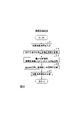
- FIG. 2 is a diagram illustrating the processing procedure of the image synthesizing method of the first embodiment.
- FIG. 3 is a diagram illustrating the functional configuration of the video synthesizing device of the second embodiment.
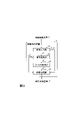
- FIG. 4 is a diagram illustrating the processing procedure of the image synthesizing method of the second embodiment.
- FIG. 5 is a diagram illustrating the functional configuration of a computer.
- a first embodiment of the present invention is a video synthesizing apparatus and method for detecting a minute color change in an arbitrary time-frequency band in a video and synthesizing a video emphasizing the detected minute color change.
- the video synthesizer 1 of the first embodiment receives a target video signal and outputs an enhanced video signal that emphasizes minute color changes in the target video signal.
- the video synthesizing device 1 includes a video input unit 11 , a signal converting unit 12 , a filtering unit 13 , an adding unit 14 and a video synthesizing unit 15 .
- the video synthesizing method of the first embodiment is realized by the video synthesizing device 1 executing the processing of each step shown in FIG.
- a video synthesizer for example, has a central processing unit (CPU: Central Processing Unit), a main memory (RAM: Random Access Memory), etc.
- CPU Central Processing Unit
- main memory RAM: Random Access Memory
- a special program is loaded into a public or dedicated computer that is a special It is a device.
- the video synthesizing device executes each process under the control of, for example, a central processing unit.
- the data input to the video synthesizer and the data obtained in each process are stored in, for example, a main memory device, and the data stored in the main memory device are read out to the central processing unit as necessary and used for other purposes.
- used to process At least a part of each processing unit included in the video synthesizer may be configured by hardware such as an integrated circuit.
- the video synthesizing method executed by the video synthesizing device 1 of the first embodiment will be described below with reference to FIG.
- a target video signal is input to the video synthesizing device 1 .
- the target video signal is, for example, a digital video signal such as an RGB signal or a YIQ signal.
- the target video signal is an RGB signal and is represented by Equation (1).
- a target video signal I c (x, y, t) input to the video synthesizer 1 is input to the video input unit 11 .
- step S11 the video input unit 11 selects one or more color signals corresponding to minute color changes to be emphasized from the input target video signal Ic (x, y, t).
- the selected color signal (hereinafter also referred to as the "target color signal”) is denoted by I g (x, y, t) is represented as
- I g (x, y, t) is represented as
- the target color signal should be read as I r (x, y, t).
- the target color signal should be read as I b (x, y, t).
- the image input unit 11 outputs the target color signal I g (x, y, t ) to the signal conversion unit 12 and the addition unit 14, and outputs the color signal I r ( x, y, t) and I b (x, y, t) are output to the image synthesizing unit 15 .
- the signal conversion unit 12 receives the target color signal I g (x, y, t) from the video input unit 11 and converts the target color signal I g (x, y, t) into multi-resolution representation. .
- it may be converted to a multi-resolution representation called a Gaussian pyramid defined by Equation (2).
- N represents the number of resolutions
- n represents the resolution index
- the signal conversion unit 12 converts the target color signal ⁇ I n g (x, y, t)
- n 1, . y, t).
- the signal conversion unit 12 outputs the target color signal I n g (x, y, t) of the selected resolution n to the filter processing unit 13 .
- step S13 the filter processing unit 13 receives the target color signal I n g (x, y, t) of resolution n from the signal conversion unit 12, and converts the desired color signal I n g (x, y, t) arbitrarily selected by the user as shown in equation (3).
- weighted enhancement time-frequency bandpass filtering is applied to the target color signal I n g (x, y, t) of resolution n based on the enhancement rate ⁇ R and the time frequency f t ⁇ R of n.
- B ng (x, y, t) represents an enhanced minute color signal obtained by enhancing only the minute color signal at the time frequency f t with the enhancement rate ⁇ .
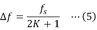
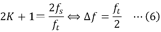
- k ⁇ [-K, K] represents the range for filtering. That is, the window width for filtering is 2K+1. Parameters d, ⁇ , and ⁇ will be described later.
- the filtering unit 13 outputs the generated enhanced minute color signal B n g (x, y, t) to the adding unit 14 .
- the processing of the filter processing unit 13 will be described in more detail below.
- the part that implements the time-frequency bandpass filtering is sLoG(k; ⁇ ).
- A(d; ⁇ ) is the part that implements the weighted emphasis filtering process. The steps will be described in order below.
- LoG(k; ⁇ ) is a filter called LoG (Laplacian of Gaussian).
- the LoG filter is defined in the form of the second derivative of the Gaussian function, as shown in Equation (4).
- Time-frequency bandpass filtering can be performed by convolving the LoG filter with the color signal.
- the problem here is how to choose the optimum window width 2K+1 and the parameter ⁇ of LoG(k; ⁇ ).
- the window width 2K+1 and the parameter ⁇ are not suitable, resulting in poor time-frequency selectivity. Therefore, in the present embodiment, it is considered to set the optimal window width 2K+1 and parameter ⁇ for time-frequency bandpass filtering.
- the window width is adaptively set as shown in Equation (6).
- the optimum parameter ⁇ is obtained by solving the optimization problem of Equation (8).
- the optimal parameter ⁇ determined above allows LoG(k; ⁇ ) to have the maximum frequency response at the time frequency f t .
- LoG(k; ⁇ ) has the maximum frequency response at the time frequency f t and is normalized to 1, so that when the enhancement factor ⁇ is applied, small color changes are purely multiplied by ⁇ . , making it easier to control the degree of emphasis. Therefore, sLoG(k; ⁇ ) obtained by scaling LoG(k; ⁇ ) is defined as in Equation (10).
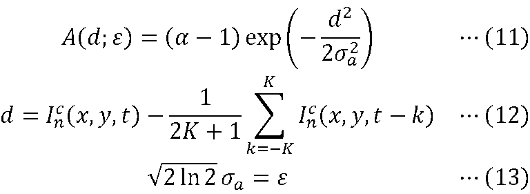
- Equation (3) The role of A(d; ⁇ ) in Equation (3) will be explained. First, A(d; ⁇ ) is defined as Equations (11)-(13).
- A(d; ⁇ ) weights the enhancement rate ⁇ based on the variation d of the color signal I n c (x, y, t). necessary to emphasize only the subtle color changes.
- step S14 the adding unit 14 receives the target color signal I g (x, y, t) from the video input unit 11 and the emphasized minute color signal B n g (x, y, t) from the filtering unit 13, Emphasis purpose is to add the signal B g (x, y, t) obtained by up-sampling the enhancement minute color signal B n g (x, y, t) to the original resolution to the target color signal I g (x, y, t) Generate the color signal ⁇ I g (x, y, t). The adder 14 outputs the generated enhancement target color signal ⁇ I g (x, y, t) to the video synthesizer 15 .
- step S15 the image synthesizing unit 15 receives the emphasized target color signal ⁇ I g (x, y, t) from the adding unit 14, and extracts colors other than the target color signal I g (x, y, t) from the video input unit 11. Take the signals I r (x, y, t), I b (x, y, t) and compute their signals ⁇ I g (x, y, t), I r (x, y, t), I b ( x, y, t) to generate an enhanced video signal ⁇ I c (x, y, t). The video synthesizing unit 15 outputs the generated enhanced video signal ⁇ I c (x, y, t) to the video synthesizing device 1 .
- a second embodiment of the present invention is a video synthesizing apparatus and method for detecting a minute motion in an arbitrary time-frequency band in a video and synthesizing a video emphasizing the detected minute motion.
- the video synthesizer 2 of the second embodiment receives a target video signal and outputs an enhanced video signal that emphasizes minute movements in the target video signal.
- the image synthesizing device 2 includes an image input unit 21 , a signal converting unit 22 , a filtering unit 23 and an image synthesizing unit 24 .
- the video synthesizing method of the second embodiment is realized by the video synthesizing device 2 executing the processing of each step shown in FIG.
- a target video signal is input to the video synthesizing device 2 .
- the target video signal is the YIQ signal and is represented by Equation (14).
- the target video signal I c (x, y, t) input to the video synthesizer 2 is input to the video input section 21 .
- step S21 the video input unit 21 selects the luminance signal Iy(x, y, t) from the input target video signal Ic (x, y , t).
- the video input unit 21 outputs the luminance signal I y (x, y, t) to the signal conversion unit 22, and converts the signal I i (x, y, t) other than the luminance signal I y (x, y, t), It outputs I q (x, y, t) to the image synthesizing section 24 .
- step S22 the signal conversion unit 22 receives the luminance signal I y (x, y, t) from the video input unit 21, and converts the luminance signal I y (x, y, t) to a plurality of band frequencies ⁇ . Transform to analytic signals in multiple directions ⁇ . This analytic signal is represented by Equation (15).
- Equation (16) the analytic signal with a certain frequency ⁇ and a certain direction ⁇ is given by Equation (16).
- R ⁇ , ⁇ y (x, y, t) is the analytic signal
- a ⁇ , ⁇ y (x, y, t) is the amplitude signal
- ⁇ ⁇ , ⁇ y (x, y, t) is the phase signal.
- ⁇ , ⁇ (x, y) is a filter group called CSF (Complex Steerable Filter).
- CSF Complex Steerable Filter
- the signal conversion unit 22 converts the analytic signal ⁇ R ⁇ , ⁇ y ( x, y , t)
- the signal conversion unit 22 outputs the selected phase signals ⁇ ⁇ , ⁇ y (x, y, t) to the filter processing unit 23 and outputs the amplitude signals A ⁇ , ⁇ y (x, y, t) to the video synthesis unit 24 .
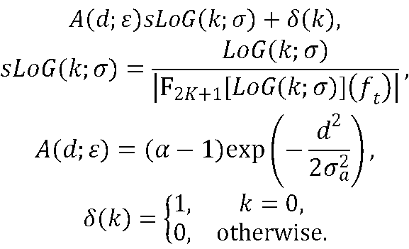
- step S23 the filtering unit 23 receives the phase signal ⁇ ⁇ , ⁇ y (x, y, t) from the signal converting unit 22, and applies a predetermined enhancement arbitrarily selected by the user as shown in equation (17). Apply a self-additive weighted enhancement time-frequency bandpass filtering to the phase signal ⁇ ⁇ , ⁇ y (x, y, t) based on the rate ⁇ R and the time-frequency f t ⁇ R.
- ⁇ ⁇ , ⁇ y (x, y, t) is the output of the filter processing unit 23, and the signal obtained by enhancing only the minute phase signal at the time frequency f t with the enhancement rate ⁇ is converted to the original phase signal. 4 represents the summed enhanced phase signal.
- sLoG(k; ⁇ ) in Equation (17) is Equation (10).
- A(d; ⁇ ) in Equation (17) is defined as in Equations (18) to (20) for phase signals.
- ⁇ (k) is defined by equation (21).
- equation (17) can be rewritten as equation (22).
- the procedure of adding the result of the weighted enhancement filtering process by A(d; ⁇ ) sLoG (k; ⁇ ) to the original phase signal ⁇ , ⁇ y(x, y , t) is performed. It means that they are integrated into one filtering process. This eliminates the need to store the original phase signal ⁇ ⁇ , ⁇ y (x,y,t) in memory, reducing the associated memory usage by a factor of 2, while allowing the phase signal ⁇ Direct conversion from ⁇ , ⁇ y (x, y, t) to the enhanced phase signal ⁇ ⁇ , ⁇ y (x, y, t) becomes possible.
- step S24 the video synthesizing unit 24 receives the amplitude signal A ⁇ , ⁇ y (x, y, t) from the signal converting unit 22, and the enhanced phase signal ⁇ ⁇ , ⁇ y (x, y, t) from the filtering unit 23. t) and generates an enhanced analytic signal ⁇ R ⁇ , ⁇ y (x, y, t) in which small motions are emphasized according to equations (23)-(24).
- the video synthesizing unit 24 generates an enhanced luminance signal ⁇ Iy (x, y, t) in which only minute movements are emphasized from the set of enhanced analysis signals ⁇ R ⁇ , ⁇ y (x, y, t). Generate. Then, the image synthesizing unit 24 receives the signals I i (x, y, t) and I q (x, y, t) other than the luminance signal I y (x, y, t) from the image input unit 21 and emphasizes them.
- the enhanced video signal ⁇ I c By combining the luminance signal ⁇ I y (x, y, t) with the signals I i (x, y, t) and I q (x, y, t), the enhanced video signal ⁇ I c (x, y, t ).
- the video synthesizing unit 24 outputs the generated enhanced video signal ⁇ I c (x, y, t) to the video synthesizing device 2 .
- the present invention simplifies the image enhancement processing algorithm for emphasizing minute changes in an image.
- the multi-stage processing performed in conventional Video Magnification has been integrated into a single filtering process. This made the algorithm more readable and easier to implement.
- the performance of Video Magnification itself has been improved, and the minute color changes and movements that users expect. It made it possible to emphasize, and reduced the occurrence of artifacts that occur during emphasis.
- memory usage can be saved at the same time.
- Computer-readable recording media are, for example, non-temporary recording media such as magnetic recording devices and optical discs.
- this program will be carried out, for example, by selling, transferring, lending, etc. portable recording media such as DVDs and CD-ROMs on which the program is recorded.
- the program may be distributed by storing the program in the storage device of the server computer and transferring the program from the server computer to other computers via the network.
- a computer that executes such a program for example, first stores a program recorded on a portable recording medium or a program transferred from a server computer once in the auxiliary recording unit 1050, which is its own non-temporary storage device. Store. When executing the process, this computer reads the program stored in the auxiliary recording unit 1050, which is its own non-temporary storage device, into the storage unit 1020, which is a temporary storage device, and follows the read program. Execute the process. Also, as another execution form of this program, the computer may read the program directly from a portable recording medium and execute processing according to the program, and the program is transferred from the server computer to this computer. Each time, the processing according to the received program may be executed sequentially.
- ASP Application Service Provider
- the above-mentioned processing is executed by a so-called ASP (Application Service Provider) type service, which does not transfer the program from the server computer to this computer, and realizes the processing function only by its execution instruction and result acquisition.
- ASP Application Service Provider
- the program in this embodiment includes information that is used for processing by a computer and that conforms to the program (data that is not a direct instruction to the computer but has the property of prescribing the processing of the computer, etc.).
- the device is configured by executing a predetermined program on a computer, but at least part of these processing contents may be implemented by hardware.
Landscapes
- Engineering & Computer Science (AREA)
- Multimedia (AREA)
- Signal Processing (AREA)
- Physics & Mathematics (AREA)
- General Physics & Mathematics (AREA)
- Theoretical Computer Science (AREA)
- Processing Of Color Television Signals (AREA)
- Image Processing (AREA)
- Transforming Electric Information Into Light Information (AREA)
- Video Image Reproduction Devices For Color Tv Systems (AREA)
Abstract
Description
この発明の第一実施形態は、映像中の任意の時間周波数帯域における微小な色変化を検出し、検出された微小な色変化を強調した映像を合成する映像合成装置およびその方法である。第一実施形態の映像合成装置1は、図1に示すように、対象映像信号を入力とし、対象映像信号中の微小な色変化を強調した強調映像信号を出力する。映像合成装置1は、映像入力部11、信号変換部12、フィルタ処理部13、加算部14、および映像合成部15を備える。この映像合成装置1が図2に示す各ステップの処理を実行することにより、第一実施形態の映像合成方法が実現される。


式(3)におけるsLoG(k; σ)の役割に関して説明する。まず、LoG(k; σ)はLoG(Laplacian of Gaussian)と呼ばれるフィルタである。LoGフィルタは、式(4)のようにガウス関数の二階微分の形で定義される.





式(3)におけるA(d; ε)の役割に関して説明する。まず、A(d; ε)は式(11)~(13)のように定義される。
この発明の第二実施形態は、映像中の任意の時間周波数帯域における微小な運動を検出し、検出された微小な運動を強調した映像を合成する映像合成装置およびその方法である。第二実施形態の映像合成装置2は、図3に示すように、対象映像信号を入力とし、対象映像信号中の微小な運動を強調した強調映像信号を出力する。映像合成装置2は、映像入力部21、信号変換部22、フィルタ処理部23、および映像合成部24を備える。この映像合成装置2が図4に示す各ステップの処理を実行することにより、第二実施形態の映像合成方法が実現される。






この発明では、映像中の微小な変化を強調する映像強調処理のアルゴリズムを単純化した。具体的には、従来のVideo Magnificationで実行される多段階的な処理を、単一のフィルタ処理に統合した。これにより、アルゴリズムの可読性を向上し、実装を容易にすることができた。また、単一のフィルタ処理に統合する中で、従来の多段階的な処理に含まれる各処理を見直すことで、Video Magnification自体の性能向上を行い、ユーザが期待する微小な色変化および運動を強調することを可能にし、かつ、強調時に発生するアーチファクトの発生を低減した。さらに、微小な運動を強調する場合には、メモリ使用量の節約も同時に実現した。
上記実施形態で説明した各装置における各種の処理機能をコンピュータによって実現する場合、各装置が有すべき機能の処理内容はプログラムによって記述される。そして、このプログラムを図5に示すコンピュータの記憶部1020に読み込ませ、演算処理部1010、入力部1030、出力部1040などに動作させることにより、上記各装置における各種の処理機能がコンピュータ上で実現される。
Claims (8)
- 入力映像から所定の解像度の色信号を抽出する信号変換部と、
前記色信号に対して重み付き強調時間周波数バンドパスフィルタを適用することで前記色信号に含まれる微小な色変化を強調した強調微小色信号を生成するフィルタ処理部と、
前記色信号と前記強調微小色信号とを用いて前記入力映像中の前記微小な色変化を強調した強調映像を合成する映像合成部と、
を含む映像合成装置。 - 請求項1に記載の映像合成装置であって、
前記重み付き強調時間周波数バンドパスフィルタは、前記色信号の変動量dに基づいて所定の強調率αを重み付けする強調関数Aと、所定の時間周波数ftにおいて周波数応答が最大となるLoGフィルタからなる、
映像合成装置。 - 請求項2に記載の映像合成装置であって、
前記重み付き強調時間周波数バンドパスフィルタは、2K+1を窓幅とし、k∈[-K, K]とし、εを前記色信号の値とし、σを前記LoGフィルタのパラメータとし、(2 ln 2)1/2σa=εとし、F2K+1[・]を一次元フーリエ変換として、次式で定義される、

映像合成装置。 - 入力映像から所望の運動変化に対応する位相信号を抽出する信号変換部と、
前記位相信号に対して自己加算型重み付き強調時間周波数バンドパスフィルタを適用することで前記位相信号に含まれる微小な位相変化を強調した強調微小位相信号を生成するフィルタ処理部と、
前記位相信号と前記強調微小位相信号とを用いて前記入力映像中の微小な運動変化を強調した強調映像を合成する映像合成部と、
を含む映像合成装置。 - 請求項4に記載の映像合成装置であって、
前記自己加算型重み付き強調時間周波数バンドパスフィルタは、2K+1を窓幅とし、k∈[-K, K]とし、εωを周波数ωにおける前記位相信号の値とし、σを前記LoGフィルタのパラメータとし、(2 ln 2)1/2σa=εωとし、F2K+1[・]を一次元フーリエ変換として、次式で定義される、
映像合成装置。 - 信号変換部が、入力映像から所定の解像度の色信号を抽出し、
フィルタ処理部が、前記色信号に対して重み付き強調時間周波数バンドパスフィルタを適用することで前記色信号に含まれる微小な色変化を強調した強調微小色信号を生成し、
映像合成部が、前記色信号と前記強調微小色信号とを用いて前記入力映像中の前記微小な色変化を強調した強調映像を合成する、
映像合成方法。 - 信号変換部が、入力映像から所望の運動変化に対応する位相信号を抽出し、
フィルタ処理部が、前記位相信号に対して自己加算型重み付き強調時間周波数バンドパスフィルタを適用することで前記位相信号に含まれる微小な位相変化を強調した強調微小位相信号を生成し、
映像合成部が、前記位相信号と前記強調微小位相信号とを用いて前記入力映像中の微小な運動変化を強調した強調映像を合成する、
映像合成方法。 - 請求項1から5のいずれかに記載の映像合成装置としてコンピュータを機能させるためのプログラム。
Priority Applications (3)
| Application Number | Priority Date | Filing Date | Title |
|---|---|---|---|
| PCT/JP2021/018210 WO2022239186A1 (ja) | 2021-05-13 | 2021-05-13 | 映像合成装置、映像合成方法、およびプログラム |
| US18/558,094 US20240221120A1 (en) | 2021-05-13 | 2021-05-13 | Video synthesis apparatus, video synthesis method, and program |
| JP2023520683A JP7513206B2 (ja) | 2021-05-13 | 2021-05-13 | 映像合成装置、映像合成方法、およびプログラム |
Applications Claiming Priority (1)
| Application Number | Priority Date | Filing Date | Title |
|---|---|---|---|
| PCT/JP2021/018210 WO2022239186A1 (ja) | 2021-05-13 | 2021-05-13 | 映像合成装置、映像合成方法、およびプログラム |
Publications (1)
| Publication Number | Publication Date |
|---|---|
| WO2022239186A1 true WO2022239186A1 (ja) | 2022-11-17 |
Family
ID=84028043
Family Applications (1)
| Application Number | Title | Priority Date | Filing Date |
|---|---|---|---|
| PCT/JP2021/018210 Ceased WO2022239186A1 (ja) | 2021-05-13 | 2021-05-13 | 映像合成装置、映像合成方法、およびプログラム |
Country Status (3)
| Country | Link |
|---|---|
| US (1) | US20240221120A1 (ja) |
| JP (1) | JP7513206B2 (ja) |
| WO (1) | WO2022239186A1 (ja) |
Family Cites Families (4)
| Publication number | Priority date | Publication date | Assignee | Title |
|---|---|---|---|---|
| US9811901B2 (en) * | 2012-09-07 | 2017-11-07 | Massachusetts Institute Of Technology | Linear-based Eulerian motion modulation |
| US9805475B2 (en) * | 2012-09-07 | 2017-10-31 | Massachusetts Institute Of Technology | Eulerian motion modulation |
| US9756316B2 (en) * | 2013-11-04 | 2017-09-05 | Massachusetts Institute Of Technology | Joint view expansion and filtering for automultiscopic 3D displays |
| CN109063763A (zh) * | 2018-07-26 | 2018-12-21 | 合肥工业大学 | 基于pca的视频微小变化放大方法 |
-
2021
- 2021-05-13 JP JP2023520683A patent/JP7513206B2/ja active Active
- 2021-05-13 US US18/558,094 patent/US20240221120A1/en active Pending
- 2021-05-13 WO PCT/JP2021/018210 patent/WO2022239186A1/ja not_active Ceased
Non-Patent Citations (5)
| Title |
|---|
| HUSSAIN YOSSRA, SHKARA AHMED A.: "Speed up Eulerian Video Motion Magnification", KURDISTAN JOURNAL OF APPLIED RESEARCH, vol. 2, no. 3, 27 August 2017 (2017-08-27), pages 14 - 17, XP093007101, ISSN: 2411-7684, DOI: 10.24017/science.2017.3.14 * |
| TAKEDA SHOICHIRO; OKAMI KAZUKI; MIKAMI DAN; ISOGAI MEGUMI; KIMATA HIDEAKI: "Jerk-Aware Video Acceleration Magnification", 2018 IEEE/CVF CONFERENCE ON COMPUTER VISION AND PATTERN RECOGNITION, IEEE, 18 June 2018 (2018-06-18), pages 1769 - 1777, XP033476141, DOI: 10.1109/CVPR.2018.00190 * |
| TAKEDA, SHOICHIRO ET AL.: "An analysis of video magnification effect on image change perception and gaze region", IEICE TECHNICAL REPORT AUDIO VISUAL AND MULTIMEDIA INFORMATION PROCESSING (AVM, 14 June 2019 (2019-06-14) * |
| WU XIU, YANG XUEZHI, JIN JING, YANG ZHAO: "Amplitude-Based Filtering for Video Magnification in Presence of Large Motion", SENSORS, vol. 18, no. 7, 17 July 2018 (2018-07-17), pages 2312, XP093007061, DOI: 10.3390/s18072312 * |
| YICHAO ZHANG; SILVIA L. PINTEA; JAN C. VAN GEMERT: "Video Acceleration Magnification", ARXIV.ORG, CORNELL UNIVERSITY LIBRARY, 201 OLIN LIBRARY CORNELL UNIVERSITY ITHACA, NY 14853, 13 April 2017 (2017-04-13), 201 Olin Library Cornell University Ithaca, NY 14853 , XP080762868, DOI: 10.1109/CVPR.2017.61 * |
Also Published As
| Publication number | Publication date |
|---|---|
| US20240221120A1 (en) | 2024-07-04 |
| JPWO2022239186A1 (ja) | 2022-11-17 |
| JP7513206B2 (ja) | 2024-07-09 |
Similar Documents
| Publication | Publication Date | Title |
|---|---|---|
| US10491856B2 (en) | Video frame interpolation using a convolutional neural network | |
| US9324005B2 (en) | Complex-valued phase-based eulerian motion modulation | |
| US9338331B2 (en) | Riesz pyramids for fast phase-based video magnification | |
| JP5655108B2 (ja) | 周波数アンラッピングによる画像リサンプリング | |
| EP2529353A1 (en) | Method and system for generating an output image of increased pixel resolution from an input image | |
| Wei | Image super‐resolution reconstruction using the high‐order derivative interpolation associated with fractional filter functions | |
| CN114494022A (zh) | 模型训练方法、超分辨率重建方法、装置、设备及介质 | |
| CN119314012B (zh) | 基于空间频率协同网络的多光谱和高光谱图像融合方法 | |
| WO2010140281A1 (ja) | 信号処理装置、信号処理装置の制御方法、制御プログラム、および該制御プログラムを記録したコンピュータ読み取り可能な記録媒体 | |
| US20060034533A1 (en) | System and method for producing a higher resolution still image from video information | |
| JP2008529151A (ja) | 複数解像度の画像フィルタリングに関するピラミッド分解 | |
| Fahmy et al. | Micro‐movement magnification in video signals using complex wavelet analysis | |
| KR20230111885A (ko) | 이미지 복원 방법 및 장치 | |
| Sidike et al. | A fast single-image super-resolution via directional edge-guided regularized extreme learning regression | |
| WO2022239186A1 (ja) | 映像合成装置、映像合成方法、およびプログラム | |
| CN119072712A (zh) | 图像处理设备及其操作方法 | |
| CN113470616A (zh) | 语音处理方法和装置以及声码器和声码器的训练方法 | |
| JP2019087126A (ja) | 画像処理装置、画像処理方法及び画像処理プログラム | |
| KR20150090515A (ko) | 고주파수 성분의 위상 변조를 통한 영상 질감 향상 방법 및 그 장치 | |
| JP7723363B2 (ja) | 虹彩認証装置、虹彩認証システム、虹彩認証方法、及び、記録媒体 | |
| Shao et al. | Partition-based interpolation for color filter array demosaicking and super-resolution reconstruction | |
| KR20160091222A (ko) | 영상 처리 장치 및 영상 처리 방법 | |
| CN111667430B (zh) | 图像的处理方法、装置、设备以及存储介质 | |
| CN117114981A (zh) | 超分网络参数调整方法、装置、设备、介质及程序产品 | |
| Brown et al. | Solid Harmonic Wavelet Bispectrum for Image Analysis |
Legal Events
| Date | Code | Title | Description |
|---|---|---|---|
| 121 | Ep: the epo has been informed by wipo that ep was designated in this application |
Ref document number: 21941919 Country of ref document: EP Kind code of ref document: A1 |
|
| WWE | Wipo information: entry into national phase |
Ref document number: 2023520683 Country of ref document: JP |
|
| WWE | Wipo information: entry into national phase |
Ref document number: 18558094 Country of ref document: US |
|
| NENP | Non-entry into the national phase |
Ref country code: DE |
|
| 122 | Ep: pct application non-entry in european phase |
Ref document number: 21941919 Country of ref document: EP Kind code of ref document: A1 |