WO2022239060A1 - システム検証装置、システム検証方法、及び、システム検証プログラム - Google Patents
システム検証装置、システム検証方法、及び、システム検証プログラム Download PDFInfo
- Publication number
- WO2022239060A1 WO2022239060A1 PCT/JP2021/017693 JP2021017693W WO2022239060A1 WO 2022239060 A1 WO2022239060 A1 WO 2022239060A1 JP 2021017693 W JP2021017693 W JP 2021017693W WO 2022239060 A1 WO2022239060 A1 WO 2022239060A1
- Authority
- WO
- WIPO (PCT)
- Prior art keywords
- function
- production environment
- status
- value
- processing system
- Prior art date
Links
- 238000012795 verification Methods 0.000 title claims abstract description 114
- 238000000034 method Methods 0.000 title claims description 21
- 238000012545 processing Methods 0.000 claims abstract description 80
- 230000006870 function Effects 0.000 claims description 200
- 238000004519 manufacturing process Methods 0.000 claims description 77
- 230000014509 gene expression Effects 0.000 description 26
- 238000010586 diagram Methods 0.000 description 13
- 230000008520 organization Effects 0.000 description 11
- 238000011161 development Methods 0.000 description 9
- 230000008569 process Effects 0.000 description 8
- 230000001186 cumulative effect Effects 0.000 description 5
- 238000011084 recovery Methods 0.000 description 4
- 230000002159 abnormal effect Effects 0.000 description 3
- 238000004891 communication Methods 0.000 description 3
- 238000005516 engineering process Methods 0.000 description 3
- 230000005856 abnormality Effects 0.000 description 2
- 230000006978 adaptation Effects 0.000 description 2
- 238000012790 confirmation Methods 0.000 description 2
- 230000004927 fusion Effects 0.000 description 2
- 230000009467 reduction Effects 0.000 description 2
- 238000012360 testing method Methods 0.000 description 2
- 238000004364 calculation method Methods 0.000 description 1
- 230000006866 deterioration Effects 0.000 description 1
- 230000000694 effects Effects 0.000 description 1
- 230000007246 mechanism Effects 0.000 description 1
- 238000012986 modification Methods 0.000 description 1
- 230000004048 modification Effects 0.000 description 1
- 230000000717 retained effect Effects 0.000 description 1
Images


Classifications
-
- G—PHYSICS
- G06—COMPUTING; CALCULATING OR COUNTING
- G06F—ELECTRIC DIGITAL DATA PROCESSING
- G06F11/00—Error detection; Error correction; Monitoring
- G06F11/30—Monitoring
- G06F11/34—Recording or statistical evaluation of computer activity, e.g. of down time, of input/output operation ; Recording or statistical evaluation of user activity, e.g. usability assessment
-
- G—PHYSICS
- G06—COMPUTING; CALCULATING OR COUNTING
- G06F—ELECTRIC DIGITAL DATA PROCESSING
- G06F11/00—Error detection; Error correction; Monitoring
- G06F11/36—Preventing errors by testing or debugging software
-
- G—PHYSICS
- G06—COMPUTING; CALCULATING OR COUNTING
- G06F—ELECTRIC DIGITAL DATA PROCESSING
- G06F8/00—Arrangements for software engineering
- G06F8/60—Software deployment
- G06F8/65—Updates
Definitions
- the present invention relates to a system verification device, a system verification method, and a system verification program.
- Non-Patent Document 1 discloses a technique for migrating a system from a test environment to a production environment.
- the present invention has been made in view of the circumstances described above, and an object of the present invention is to provide a technology that allows easy implementation of system upgrades in the production environment.
- a system verification apparatus includes a management unit that manages a function status related to the execution status of functions of the processing system using log data of a processing system built in a verification environment, and a value based on the function status. a determining unit that determines whether the value satisfies the application condition value to the production environment; and a renewal unit that switches the function of the processing system to the production environment when the value based on the function status satisfies the application condition value to the production environment. , provided.
- a system verification apparatus includes a management unit that manages a function status related to the execution status of functions of the processing system using log data of a processing system built in a production environment, and a value based on the function status. a judgment unit for judging whether or not satisfies the discontinued use condition value in the production environment; and a renaming unit that returns to .
- a system verification method comprises the steps of: a system verification device managing a function status related to the execution status of a function of the processing system using log data of a processing system constructed in a verification environment; determining whether the value based on the status satisfies the conditional value for applicability to the production environment; and switching the function of the processing system to the production environment if the value based on the function status satisfies the conditional value for applicability to the production environment. Step and do.
- a system verification method comprises the steps of: a system verification device managing a function status related to the execution status of a function of the processing system using log data of a processing system built in a production environment; determining whether a status-based value satisfies a discontinued use condition value in a production environment; and a step of reverting to the functionality of the old version.
- a system verification program causes a computer to function as the system verification device.
- FIG. 1 is a diagram showing the whole.
- FIG. 2 is a diagram showing a configuration example of functional blocks of the system verification device 1.
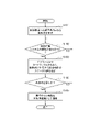
- FIG. 3 is a diagram showing an operation example 1 of the system verification device 1.
- FIG. 4 is a diagram showing a processing image of operation example 1.
- FIG. 5 is a diagram illustrating a notification example in operation example 1.
- FIG. FIG. 6 is a diagram showing an operation example 2 of the system verification device 1.
- FIG. FIG. 7 is a diagram showing a processing image of Operation Example 2.
- FIG. FIG. 8 is a diagram illustrating a notification example in Operation Example 2.
- FIG. FIG. 9 is a diagram showing an example of management of function status.
- FIG. 10 is a diagram showing a hardware configuration example of the system verification device 1. As shown in FIG.
- the present invention accumulates and manages the processing contents of the system and the results of execution in the verification environment (influence on other devices, normal execution rate, etc.), and the conditions that the actual results are prescribed in advance (the conditions that the development organization approves the verification) etc.) is satisfied, a system verification device is disclosed that performs a predetermined process.
- a pre-defined process for example, by registering the process of applying the system to the production environment and updating (Patent No. 5052472, etc.), the system can be automatically updated when the conditions are met. can.
- the present invention accumulates and manages the results of executing the system in the production environment (normal execution rate, processing time, etc.), and the conditions prescribed in advance by the actual results (such as conditions where the development organization makes continuous use NG).
- a system verification device that performs a predetermined operation when the conditions are satisfied. For example, by registering system recovery processing as the predetermined operation, the system can be automatically recovered when the conditions are met.
- the above system verification device it is possible for the operator to easily check the quality of the system and automatically apply it to the production environment.
- the system can be automatically restored when there is an abnormality in quality. It is no longer necessary to coordinate between the development organization and the operation organization for each renewal, and a reduction in the amount of work involved in verification and operation can be expected.
- the system verification device has a function of managing the status of each function in the verification environment of the system, and a function of managing the status of each function in the verification environment of the system and and a function of managing the status of each function.
- the status of each function is the normal execution rate of each function.
- users of the system verification device 1 (developers of the development organization, verifiers of the verification organization, operators of the operation organization, etc.) appropriately execute the system in the verification environment. For example, an operation for system proficiency is assumed.
- a log file is generated in the verification environment system as a history of function execution of the system.
- the system verification device 1 calculates and manages the normal execution rate and the like for each function of the system based on the log files and code files of the system. Then, when the normal execution rate of each function satisfies a predetermined conditional expression (when sufficient quality is ensured), the system verification device 1 executes a predetermined process to Apply/update the function that satisfies the conditional expression to the production environment.
- the user of the system verification device 1 appropriately executes the system in the production environment. For example, normal operation of the system is assumed. At this time, a log file is generated in the production environment system as a history of function execution of the system. The system verification device 1 calculates and manages the normal execution rate and processing time of each function in the production environment based on the log files and code files of the system. Then, when the normal execution rate of each function, the processing time, and the like satisfy a predetermined conditional expression (when abnormal deterioration in quality is observed), the system verification apparatus 1 The function that satisfies the conditional expression is restored by executing the process specified by the conditional expression.
- FIG. 2 is a diagram showing a configuration example of functional blocks of the system verification device 1 according to this embodiment.
- the system verification device 1 includes a system status manager 10 .
- the system status management unit 10 has a function of managing the status of each function of the verification environment processing system developed and modified by the developer.
- the system status management unit 10 also has a function of managing the status of each function of the production environment processing system in which the service is in actual operation.
- the system status management unit 10 includes, for example, a management unit 11, a determination unit 12, a renewal unit 13, a message definition file DB 14, a function status DB 15, and a conditional expression DB 16. , provided.
- the names of these functional units may be expressed as processing unit, execution unit, control unit, processing execution unit, storage unit, and the like.
- a plurality of functional units may be integrated into a single functional unit, or a single functional unit may be divided into a plurality of functional units.
- the management unit 11 has a function of managing the function status related to the execution status of the functions of the system using the log files and code files of the system built in the verification environment. Also, the management unit 11 has a function of managing the function status related to the execution status of the functions of the system using log files and code files of the system constructed in the production environment.
- the determination unit 12 has a function of determining whether the value based on the function status satisfies the application condition value for the production environment. Further, the determination unit 12 has a function of determining whether or not the value based on the function status satisfies the discontinued use condition value in the production environment.
- the update unit 13 has a function to switch the system function to the production environment by executing a predetermined process when the value based on the function status satisfies the application condition value to the production environment. In addition, when the value based on the function status satisfies the discontinued use condition value in the production environment, the updating unit 13 executes a predetermined process to restore the function of the system to the function of the old version. ) function.
- the message definition file DB 14 has a function of storing message definition files that define key information for obtaining predetermined messages from log files and code files.
- the function status DB 15 has a function of storing function statuses related to the execution status of system functions.
- the conditional expression DB 16 has a function of storing applicable condition values to the production environment and discontinued use condition values in the production environment.
- FIG. 3 is a diagram showing an operation example 1 of the system verification device 1. As shown in FIG. It is assumed that the user of the system verification device 1 is properly running the system in the verification environment. For example, an operation for system proficiency is assumed.
- Step S101 First, the operator of the system verification device 1 creates and determines in advance application conditions (applicable condition values to the production environment) that serve as criteria for application to the production environment. Then, the system verification device 1 registers the determined applicable conditions as a conditional expression list in the conditional expression DB 16 .
- the operator of the system verification device 1 has the degree of impact on the production environment automatically calculated by scanning the code of the function, and the normal execution rate of the function calculated from the execution result of the function. , is registered as a conditional expression list.
- “Low” is set for the impact when the function code is read-only, such as HTTP GET only.
- the function code includes write processing such as "registration”, “delete”, and “update”, such as HTTP POST, "high” is set.
- a value corresponding to the degree of impact is set in the normal execution rate. For example, when the degree of influence is “low”, “90% or more” is set. If the degree of influence is “high”, “95% or more” is set.
- Step S102 the system verification device 1 determines whether or not the function of the system in the verification environment has been executed.
- the system verification device 1 refers to the log file generated by the system, and determines that the function has been executed when a log indicating the execution of the function is newly added to the log file.
- the system verification device 1 proceeds to step S103 if the function is executed, and repeats step S102 until the function is executed if the function is not executed.
- Step S103 Each time the system functions are executed in the verification environment, the system verification device 1 acquires, calculates, and updates values corresponding to the application conditions of the conditional expression list.
- the management unit 11 of the system verification device 1 acquires the log file of the system and the code file of the executed function from the system of the verification environment. Then, the management unit 11 acquires the acquisition target message defined in the message definition file from the log file or code file. After that, the management unit 11 updates the value corresponding to the application condition of the conditional expression list based on the acquisition target message. For example, when function A is executed, the execution count and normal execution count included in the function status of function A are updated as shown in FIG.
- the management unit 11 updates the function status of each executed function, and stores the updated function status in the function status DB 15. to manage.
- Step S104 Each time the function status is updated, the system verification device 1 checks whether the updated function status satisfies the application conditions of the conditional expression list.
- the determination unit 12 of the system verification device 1 calculates the current normal execution rate [%] of the function A by dividing the number of normal executions included in the function status of the updated function A by the number of executions. . After that, as shown in FIG. 4, the determination unit 12 compares the current normal execution rate EX1 of the function A with the normal execution rate EX2 of the function A registered in the conditional expression list.
- the determination unit 12 determines that the application condition, which is the criterion for application to the production environment, is satisfied for the function A, and proceeds to step S104.
- the determination unit 12 determines that the function A does not meet the application criteria for application to the production environment, and returns to step S102.
- Step S105 If the adaptation condition is satisfied, the system verification device 1 introduces the system into the operational environment.
- the updating unit 13 of the system verification device 1 may apply By executing predetermined processing such as switching processing of setting information of the disclosed program, the functions that satisfy the application conditions are applied and updated to the production environment.
- the verification environment is built on a LAN environment common to the production environment, and the update unit 13 rewrites the system address setting to the address setting of the production environment, thereby applying the function that satisfies the application condition to the production environment. ⁇ Update.
- the updating unit 13 displays a switching confirmation message as shown in FIG. You may make it apply to an environment.
- FIG. 6 is a diagram showing an operation example 2 of the system verification device 1. As shown in FIG. It is assumed that the user of the system verification device 1 is properly running the system in the production environment. For example, normal operation of the system is assumed.
- Step S201 First, the operator of the system verification device 1 creates and determines in advance an application condition (non-continuous usage condition value in the production environment) that serves as an application criterion for functional recovery in the production environment. Then, the system verification device 1 registers the determined applicable conditions as a conditional expression list in the conditional expression DB 16 .
- the operator of the system verification device 1 registers, as a conditional expression list, a processing time divergence value that indicates how much the latest processing time of a function exceeds the past average processing time. do.
- Step S202 the system verification device 1 determines whether or not the function of the system in the production environment has been executed.
- the system verification device 1 refers to the log file generated by the system, and determines that the function has been executed when a log indicating the execution of the function is newly added to the log file.
- the system verification device 1 proceeds to step S203 if the function is executed, and repeats step S202 until the function is executed if the function is not executed.
- Step S203 Each time the system functions are executed in the production environment, the system verification device 1 acquires, calculates, and updates values corresponding to the application conditions of the conditional expression list.
- the management unit 11 of the system verification device 1 acquires the log file of the system and the code file of the executed function from the production environment system. Then, the management unit 11 acquires the acquisition target message defined in the message definition file from the log file or code file. After that, the management unit 11 updates the value corresponding to the application condition of the conditional expression list based on the acquisition target message. For example, when function A is executed, the average processing time and the latest processing time included in the function status of function A are updated as shown in FIG.
- the management unit 11 updates the function status of each executed function each time each function of the system is executed in the production environment, and stores the updated function status in the function status DB 15. to manage.
- Step S204 Each time the function status is updated, the system verification device 1 checks whether the updated function status satisfies the application conditions of the conditional expression list.
- the determination unit 12 of the system verification device 1 divides the latest processing time included in the function status of the function A after updating by the average processing time, thereby obtaining the divergence value [%] of the current processing time of the function A. Calculate Thereafter, as shown in FIG. 7, the determination unit 12 compares the deviation value DI1 of the processing time of the function A at the present time with the deviation value DI2 of the processing time of the function A registered in the conditional expression list. do.
- step S204 determines that the function A satisfies the application condition, which is the application criterion for functional recovery in the production environment.
- step S204 determines that the function A does not satisfy the application condition that serves as the application criterion for functional recovery in the production environment.
- Step S205 If the adaptation condition is satisfied, the system verification device 1 introduces the system into the operational environment.
- the updating unit 13 of the system verification device 1 preliminarily By executing the specified processing, the functions that satisfy the applicable conditions are restored.
- the update unit 13 restores the function that satisfies the application condition by inputting a command to switch the connection destination of the function to the function of the old version.
- the updating unit 13 displays a switching confirmation message as shown in FIG. may be executed.
- the operator of the system verification device 1 checks execution messages, end messages, etc., in log files and code files in order to determine whether execution of functions, termination of execution, etc., is included in log files and code files.
- a character string included in is defined in advance.
- the system verification device 1 records the defined character string in the message definition file and registers the message definition file in the message definition file DB 14 .
- the operator of the system verification device 1 has "executed” as an execution message, a processing ID as linking information, a "normal end” or “abnormal end” as an end message, and a normal end message
- record a character string such as "normal termination” as a message and "post” as an impact determination message.
- the management unit 11 of the system verification device 1 scans the log data of the log files in the system and the code data of the code files, the management unit 11 reads the character strings recorded in the message definition file to replace the character strings. Depending on whether or not it is included, information necessary for managing the function status, such as "executed”, “finished”, “completed normally”, etc., is detected in log files and code files.
- the management unit 11 performs log From the log information in the file, obtain target messages such as the ID of the executed function, execution result (normal end or abnormal end), execution start time, and execution end time.
- the function status includes, for example, the number of function executions, the number of normal executions, the latest execution time, the degree of influence, the average processing time, the latest processing time, the cumulative processing time, and the like.
- the number of executions and the number of normal executions are calculated for each function execution unit, function update unit, or system update unit. Specifically, if the execution end time of a function included in the log file acquired by regular execution is newer than the latest time accumulated in the function status of the function, add 1 to the execution count of the function status. do. Also, if the execution of the function has ended normally, 1 is added to the number of times of normal execution.
- search for the message "Function A was executed” in the log file and if the execution time of function A has not already been checked, add it to the number of executions. Also, if the result code corresponding to the message indicates normal termination, it is added to the number of normal executions.
- the latest execution time is the execution end time of the function contained in the log file.
- the degree of impact is also calculated for each function execution unit, each function update unit, or each system update unit.
- the code file of the executed function is searched, and if it has the register/update/delete function, it is set to "high", and if it does not have it, it is set to "low". For example, in the case of REST format, if "POST" is included in the code file, it will be “high”, and if "POST” is not included, it will be “low”.
- the impact of each function is updated when the execution time of the executed function is updated.
- the code file is, for example, the source code of the function before compilation, or the source code included in the file of the function if the function can be executed without compiling.
- the average processing time, latest processing time, and cumulative processing time are also calculated for each function execution unit, function update unit, or system update unit. Specifically, if the execution end time of the function included in the log file acquired by regular execution is newer than the latest time accumulated in the function status of the function, the execution end time and the execution end time The associated execution start time is acquired, and a value obtained by subtracting the execution start time from the execution end time is set as the latest processing time. Also, the cumulative processing time is updated by adding the latest processing time to the cumulative processing time of the function status. Also, a value obtained by dividing the cumulative processing time by the number of times of execution is defined as the average processing time.
- the system verification apparatus 1 includes the management unit 11 that manages the function status related to the execution status of the functions of the processing system using the log data of the processing system constructed in the verification environment, and the function status and a determining unit 12 for determining whether the value based on the function status satisfies the application condition value to the production environment, and if the value based on the function status satisfies the application condition value to the production environment, the function of the processing system is transferred to the production environment. and a updating unit 13 for switching.
- the system verification device 1 uses the log data of the processing system built in the production environment to manage the function status related to the execution status of the functions of the processing system; a determining unit 12 for determining whether a value based on the function status satisfies the discontinued use condition value in the production environment; and if the value based on the function status satisfies the discontinued use condition value in the production environment, the processing system and a renewal unit 13 for returning the function of the old version to the function of the old version.
- the system verification device By using the above system verification device, it is possible for the operator to easily check the quality of the system and automatically apply it to the production environment. That is, as long as the user (operator) of the system verification device performs an operation for proficiency, the system verification device automatically applies the system to the production environment.
- the system verification device 1 of this embodiment described above includes, for example, a CPU 901, a memory 902, a storage 903, a communication device 904, an input device 905, and an output device 906, as shown in FIG. It can be realized using a general-purpose computer system.
- Memory 902 and storage 903 are storage devices.
- each function of the system verification apparatus 1 is realized by the CPU 901 executing a predetermined program loaded on the memory 902 .
- the system verification device 1 may be implemented by one computer.
- the system verification device 1 may be implemented by multiple computers.
- the system verification device 1 may be a virtual machine implemented on a computer.
- a program for the system verification device 1 can be stored in computer-readable recording media such as HDD, SSD, USB memory, CD, and DVD.
- the program for system verification device 1 can also be distributed via a communication network.
- System verification device 10 System status management unit 11: Management unit 12: Judgment unit 13: Renewal unit 14: Message definition file DB 15: Function status DB 16: Conditional expression DB 901: CPU 902: Memory 903: Storage 904: Communication device 905: Input device 906: Output device
Landscapes
- Engineering & Computer Science (AREA)
- Theoretical Computer Science (AREA)
- General Engineering & Computer Science (AREA)
- Physics & Mathematics (AREA)
- General Physics & Mathematics (AREA)
- Software Systems (AREA)
- Computer Hardware Design (AREA)
- Quality & Reliability (AREA)
- Computer Security & Cryptography (AREA)
- Debugging And Monitoring (AREA)
Abstract
Description
本発明は、システムの処理内容や検証環境で実行した実績(他装置に与える影響、正常実行率等)を蓄積・管理し、当該実績値が予め規定した条件(開発組織が検証OKとする条件等)を満たした場合に、事前に規定した処理を行うシステム検証装置を開示する。当該事前に規定した処理として、例えば、システムを本番環境に適用して更新する処理(特許第5052472号等)を登録しておくことで、条件を満たした際に自動でシステムを更新することができる。
本実施形態に係るシステム検証装置は、開発者が開発・改造した1つ以上の機能を有する処理システムについて、当該システムの検証環境における機能単位のステータスを管理する機能と、当該システムの本番環境における機能単位のステータスを管理する機能と、を備える。機能単位のステータスとは、各機能の正常実行率等である。
図2は、本実施形態に係るシステム検証装置1の機能ブロックの構成例を示す図である。当該システム検証装置1は、システムステータス管理部10を備える。システムステータス管理部10は、開発者が開発・改造した検証環境の処理システムについて、当該システムの各機能のステータスを管理する機能を備える。また、システムステータス管理部10は、サービスの実運用中である本番環境の処理システムについて、当該システムの各機能のステータスを管理する機能を備える。
[動作例1]
図3は、システム検証装置1の動作例1を示す図である。システム検証装置1の利用者は、システムを検証環境にて適当に実行していると仮定する。例えば、システムの習熟のための操作が想定される。
まず、システム検証装置1の運用者は、予め本番環境への適用基準となる適用条件(本番環境への適用条件値)を作成して決定しておく。そして、システム検証装置1は、当該決定された適用条件を条件式リストとして条件式DB16に登録しておく。
次に、システム検証装置1は、検証環境のシステムの機能が実行されたか否かを判定する。例えば、システム検証装置1は、当該システムが生成するログファイルを参照し、当該ログファイルに機能の実行を示すログが新規に追加されている場合、機能が実行されたと判定する。システム検証装置1は、機能が実行された場合にはステップS103へ進み、機能が実行されていない場合にはステップS102を機能が実行されるまで繰り返す。
検証環境でシステムの機能が実行される毎に、システム検証装置1は、上記条件式リストの適用条件に対応する値を取得・計算・更新する。
機能ステータスが更新される毎に、システム検証装置1は、更新後の機能ステータスが上記条件式リストの適用条件を満たしているかを確認する。
適応条件を満たす場合、システム検証装置1は、当該システムを運用環境に導入する。
図6は、システム検証装置1の動作例2を示す図である。システム検証装置1の利用者は、システムを本番環境にて適当に実行していると仮定する。例えば、システムの通常運転が想定される。
まず、システム検証装置1の運用者は、予め本番環境の機能復旧の適用基準となる適用条件(本番環境での非継続使用条件値)を作成して決定しておく。そして、システム検証装置1は、当該決定された適用条件を条件式リストとして条件式DB16に登録しておく。
次に、システム検証装置1は、本番環境のシステムの機能が実行されたか否かを判定する。例えば、システム検証装置1は、当該システムが生成するログファイルを参照し、当該ログファイルに機能の実行を示すログが新規に追加されている場合、機能が実行されたと判定する。システム検証装置1は、機能が実行された場合にはステップS203へ進み、機能が実行されていない場合にはステップS202を機能が実行されるまで繰り返す。
本番環境でシステムの機能が実行される毎に、システム検証装置1は、上記条件式リストの適用条件に対応する値を取得・計算・更新する。
機能ステータスが更新される毎に、システム検証装置1は、更新後の機能ステータスが上記条件式リストの適用条件を満たしているかを確認する。
適応条件を満たす場合、システム検証装置1は、当該システムを運用環境に導入する。
[取得対象メッセージの取得方法]
ステップS103、ステップS203で行う、ログファイルやコードファイルからの取得対象メッセージの取得方法を説明する。
ステップS103、ステップS203で行う、機能ステータスの更新方法を説明する。
ステップS104では、正常実行回数を実行回数で除算することで正常実行率を算出した。しかし、その算出方法で正常実行率を求めると1回実行して1回成功した場合には正常実行率が100%となるので、実績が不十分な際に条件式を満たしやすくなってしまう。そこで、次の実行回には実行が失敗したものと仮定した正常実行回数を用いて正常実行率を算出してもよい。すなわち、正常実行回数から所定数を減算した値を実行回数で除算した値を正常実行率とする。例えば、9回実行して9回成功した後、10回目の実行は成功であってもあえて失敗したと仮定して正常実行率を90%(=9÷10)とする。これにより、実績が不十分な場合を排除しやすくなる。
本実施形態によれば、システム検証装置1は、検証環境に構築された処理システムのログデータを用いて、前記処理システムの機能の実行状況に関する機能ステータスを管理する管理部11と、前記機能ステータスに基づく値が本番環境への適用条件値を満たすかを判定する判定部12と、前記機能ステータスに基づく値が前記本番環境への適用条件値を満たす場合、前記処理システムの機能を本番環境へ切り替える更改部13と、を備える。
本発明は、上記実施形態に限定されない。本発明は、本発明の要旨の範囲内で数々の変形が可能である。
10:システムステータス管理部
11:管理部
12:判定部
13:更改部
14:メッセージ定義ファイルDB
15:機能ステータスDB
16:条件式DB
901:CPU
902:メモリ
903:ストレージ
904:通信装置
905:入力装置
906:出力装置
Claims (8)
- 検証環境に構築された処理システムのログデータを用いて、前記処理システムの機能の実行状況に関する機能ステータスを管理する管理部と、
前記機能ステータスに基づく値が本番環境への適用条件値を満たすかを判定する判定部と、
前記機能ステータスに基づく値が前記本番環境への適用条件値を満たす場合、前記処理システムの機能を本番環境へ切り替える更改部と、
を備えるシステム検証装置。 - 本番環境に構築された処理システムのログデータを用いて、前記処理システムの機能の実行状況に関する機能ステータスを管理する管理部と、
前記機能ステータスに基づく値が本番環境での非継続使用条件値を満たすかを判定する判定部と、
前記機能ステータスに基づく値が前記本番環境での非継続使用条件値を満たす場合、前記処理システムの機能を旧版の機能に戻す更改部と、
を備えるシステム検証装置。 - 前記更改部は、
前記機能ステータスに基づく機能の正常実行率が前記本番環境への適用条件値を満たす場合、前記処理システムの機能を本番環境へ切り替える請求項1に記載のシステム検証装置。 - 前記更改部は、
前記機能ステータスに基づく機能の最新処理時間と平均処理時間との乖離値が前記本番環境での非継続使用条件値を満たす場合、前記処理システムの機能を旧版の機能に戻す請求項2に記載のシステム検証装置。 - 前記機能の正常実行率は、
正常実行回数から所定数を減算した値を実行回数で除算した値である請求項3に記載のシステム検証装置。 - システム検証装置が、
検証環境に構築された処理システムのログデータを用いて、前記処理システムの機能の実行状況に関する機能ステータスを管理するステップと、
前記機能ステータスに基づく値が本番環境への適用条件値を満たすかを判定するステップと、
前記機能ステータスに基づく値が前記本番環境への適用条件値を満たす場合、前記処理システムの機能を本番環境へ切り替えるステップと、
を行うシステム検証方法。 - システム検証装置が、
本番環境に構築された処理システムのログデータを用いて、前記処理システムの機能の実行状況に関する機能ステータスを管理するステップと、
前記機能ステータスに基づく値が本番環境での非継続使用条件値を満たすかを判定するステップと、
前記機能ステータスに基づく値が前記本番環境での非継続使用条件値を満たす場合、前記処理システムの機能を旧版の機能に戻すステップと、
を行うシステム検証方法。 - 請求項1乃至5のいずれかに記載のシステム検証装置としてコンピュータを機能させるシステム検証プログラム。
Priority Applications (2)
| Application Number | Priority Date | Filing Date | Title |
|---|---|---|---|
| PCT/JP2021/017693 WO2022239060A1 (ja) | 2021-05-10 | 2021-05-10 | システム検証装置、システム検証方法、及び、システム検証プログラム |
| JP2023520581A JPWO2022239060A1 (ja) | 2021-05-10 | 2021-05-10 |
Applications Claiming Priority (1)
| Application Number | Priority Date | Filing Date | Title |
|---|---|---|---|
| PCT/JP2021/017693 WO2022239060A1 (ja) | 2021-05-10 | 2021-05-10 | システム検証装置、システム検証方法、及び、システム検証プログラム |
Publications (1)
| Publication Number | Publication Date |
|---|---|
| WO2022239060A1 true WO2022239060A1 (ja) | 2022-11-17 |
Family
ID=84028488
Family Applications (1)
| Application Number | Title | Priority Date | Filing Date |
|---|---|---|---|
| PCT/JP2021/017693 WO2022239060A1 (ja) | 2021-05-10 | 2021-05-10 | システム検証装置、システム検証方法、及び、システム検証プログラム |
Country Status (2)
| Country | Link |
|---|---|
| JP (1) | JPWO2022239060A1 (ja) |
| WO (1) | WO2022239060A1 (ja) |
Citations (5)
| Publication number | Priority date | Publication date | Assignee | Title |
|---|---|---|---|---|
| JP2005250732A (ja) * | 2004-03-03 | 2005-09-15 | Fujitsu Ltd | バージョンアップ制御プログラムおよびバージョンアップ制御方法 |
| JP2006099393A (ja) * | 2004-09-29 | 2006-04-13 | Sharp Corp | ファームウェア管理装置、ファームウェア管理プログラム、電子機器、記録媒体、及びファームウェア管理方法 |
| JP2010231488A (ja) * | 2009-03-27 | 2010-10-14 | Fujitsu Ltd | 監視システム、監視プログラム及び監視方法 |
| JP2016189087A (ja) * | 2015-03-30 | 2016-11-04 | ビッグローブ株式会社 | 基盤ソフト運用管理システム、基盤ソフト運用管理装置、制御方法およびプログラム |
| JP2020030506A (ja) * | 2018-08-21 | 2020-02-27 | 三菱電機株式会社 | 制御システムの検証システム及びパッチ適用判定装置 |
-
2021
- 2021-05-10 WO PCT/JP2021/017693 patent/WO2022239060A1/ja active Application Filing
- 2021-05-10 JP JP2023520581A patent/JPWO2022239060A1/ja active Pending
Patent Citations (5)
| Publication number | Priority date | Publication date | Assignee | Title |
|---|---|---|---|---|
| JP2005250732A (ja) * | 2004-03-03 | 2005-09-15 | Fujitsu Ltd | バージョンアップ制御プログラムおよびバージョンアップ制御方法 |
| JP2006099393A (ja) * | 2004-09-29 | 2006-04-13 | Sharp Corp | ファームウェア管理装置、ファームウェア管理プログラム、電子機器、記録媒体、及びファームウェア管理方法 |
| JP2010231488A (ja) * | 2009-03-27 | 2010-10-14 | Fujitsu Ltd | 監視システム、監視プログラム及び監視方法 |
| JP2016189087A (ja) * | 2015-03-30 | 2016-11-04 | ビッグローブ株式会社 | 基盤ソフト運用管理システム、基盤ソフト運用管理装置、制御方法およびプログラム |
| JP2020030506A (ja) * | 2018-08-21 | 2020-02-27 | 三菱電機株式会社 | 制御システムの検証システム及びパッチ適用判定装置 |
Also Published As
| Publication number | Publication date |
|---|---|
| JPWO2022239060A1 (ja) | 2022-11-17 |
Similar Documents
| Publication | Publication Date | Title |
|---|---|---|
| JP7090657B2 (ja) | アプリケーションをアップグレードするための方法、装置、デバイスならびに記憶媒体 | |
| US10019256B2 (en) | Systems and methods for incremental software development | |
| JP5444368B2 (ja) | アプリケーション復元ポイント | |
| KR102055024B1 (ko) | 클라이언트측 최소 다운로드 및 시뮬레이션 페이지 네비게이션 기능 | |
| CN106575244B (zh) | 确保云应用的高可用性的修补过程 | |
| US20170371639A1 (en) | Updating live system with static changes | |
| US9754242B2 (en) | Deployment mechanism for non-versioning business process artifacts | |
| JP2014142678A (ja) | 仮想サーバ移行計画作成方法およびシステム | |
| US11880674B2 (en) | Adaptive hot reload for class changes | |
| US11983519B2 (en) | Abort installation of firmware bundles | |
| US20130086572A1 (en) | Generation apparatus, generation method and computer readable information recording medium | |
| US11467918B2 (en) | System and method for resilient backup generation | |
| WO2022239060A1 (ja) | システム検証装置、システム検証方法、及び、システム検証プログラム | |
| US20090276779A1 (en) | Job management apparatus | |
| JP6468098B2 (ja) | 情報処理プログラム、装置、及び方法 | |
| CN111737964A (zh) | 表格动态处理方法、设备及介质 | |
| JP2014006845A (ja) | 管理方法,管理装置および管理プログラム | |
| JP6045707B2 (ja) | ライセンス管理装置、ライセンス管理方法、及びプログラム | |
| JP6481489B2 (ja) | 修正適用情報作成プログラム、修正適用情報作成装置及び修正適用情報作成方法 | |
| JP6555908B2 (ja) | 情報処理装置及びその制御方法、プログラム | |
| US11424982B2 (en) | Remediation of a system to new desired state using configuration dependency graph | |
| JP2013105349A (ja) | 動的リンクライブラリの更新、実行方法 | |
| WO2017076180A1 (zh) | 虚拟机升级方法及装置 | |
| US10496059B2 (en) | Operational control management apparatus and operational control management method | |
| US20240143411A1 (en) | Method for automatically maintaining an infrastructure as code state of a resource space hosted on a cloud platform |
Legal Events
| Date | Code | Title | Description |
|---|---|---|---|
| 121 | Ep: the epo has been informed by wipo that ep was designated in this application |
Ref document number: 21941794 Country of ref document: EP Kind code of ref document: A1 |
|
| WWE | Wipo information: entry into national phase |
Ref document number: 2023520581 Country of ref document: JP |
|
| WWE | Wipo information: entry into national phase |
Ref document number: 18288535 Country of ref document: US |
|
| NENP | Non-entry into the national phase |
Ref country code: DE |
|
| 122 | Ep: pct application non-entry in european phase |
Ref document number: 21941794 Country of ref document: EP Kind code of ref document: A1 |