WO2022237005A1 - 一种可升降式太阳能组件自清洁防护装置及使用方法 - Google Patents
一种可升降式太阳能组件自清洁防护装置及使用方法 Download PDFInfo
- Publication number
- WO2022237005A1 WO2022237005A1 PCT/CN2021/114961 CN2021114961W WO2022237005A1 WO 2022237005 A1 WO2022237005 A1 WO 2022237005A1 CN 2021114961 W CN2021114961 W CN 2021114961W WO 2022237005 A1 WO2022237005 A1 WO 2022237005A1
- Authority
- WO
- WIPO (PCT)
- Prior art keywords
- cleaning
- rotating shaft
- power generation
- energy storage
- liftable
- Prior art date
Links
- 238000004140 cleaning Methods 0.000 title claims abstract description 79
- 238000000034 method Methods 0.000 title claims abstract description 14
- 238000010248 power generation Methods 0.000 claims abstract description 69
- 239000004744 fabric Substances 0.000 claims abstract description 55
- 238000004146 energy storage Methods 0.000 claims abstract description 44
- XLYOFNOQVPJJNP-UHFFFAOYSA-N water Substances O XLYOFNOQVPJJNP-UHFFFAOYSA-N 0.000 claims description 17
- 239000002184 metal Substances 0.000 claims description 13
- 238000002844 melting Methods 0.000 claims description 12
- 230000008018 melting Effects 0.000 claims description 12
- 230000005611 electricity Effects 0.000 claims description 6
- 239000004372 Polyvinyl alcohol Substances 0.000 claims description 5
- 229920002451 polyvinyl alcohol Polymers 0.000 claims description 5
- 230000008569 process Effects 0.000 claims description 4
- 239000004677 Nylon Substances 0.000 claims description 3
- 229920001778 nylon Polymers 0.000 claims description 3
- 230000001681 protective effect Effects 0.000 claims 6
- 239000003292 glue Substances 0.000 claims 1
- 239000000155 melt Substances 0.000 claims 1
- 230000000694 effects Effects 0.000 abstract description 2
- 230000000903 blocking effect Effects 0.000 abstract 5
- 238000011086 high cleaning Methods 0.000 abstract 1
- 230000006872 improvement Effects 0.000 description 7
- 230000000873 masking effect Effects 0.000 description 3
- 238000010586 diagram Methods 0.000 description 2
- 239000000428 dust Substances 0.000 description 2
- 239000003344 environmental pollutant Substances 0.000 description 2
- 238000012423 maintenance Methods 0.000 description 2
- 231100000719 pollutant Toxicity 0.000 description 2
- 238000003825 pressing Methods 0.000 description 2
- 238000009825 accumulation Methods 0.000 description 1
- 230000009471 action Effects 0.000 description 1
- 230000009286 beneficial effect Effects 0.000 description 1
- 230000005540 biological transmission Effects 0.000 description 1
- 238000006243 chemical reaction Methods 0.000 description 1
- 230000003749 cleanliness Effects 0.000 description 1
- 150000001875 compounds Chemical class 0.000 description 1
- 238000005265 energy consumption Methods 0.000 description 1
- 238000005516 engineering process Methods 0.000 description 1
- 230000007613 environmental effect Effects 0.000 description 1
- 239000011521 glass Substances 0.000 description 1
- 238000007689 inspection Methods 0.000 description 1
- 230000002427 irreversible effect Effects 0.000 description 1
- 230000009467 reduction Effects 0.000 description 1
- 239000004576 sand Substances 0.000 description 1
- 238000009475 tablet pressing Methods 0.000 description 1
Images


Classifications
-
- H—ELECTRICITY
- H02—GENERATION; CONVERSION OR DISTRIBUTION OF ELECTRIC POWER
- H02S—GENERATION OF ELECTRIC POWER BY CONVERSION OF INFRARED RADIATION, VISIBLE LIGHT OR ULTRAVIOLET LIGHT, e.g. USING PHOTOVOLTAIC [PV] MODULES
- H02S40/00—Components or accessories in combination with PV modules, not provided for in groups H02S10/00 - H02S30/00
- H02S40/10—Cleaning arrangements
- H02S40/12—Means for removing snow
-
- Y—GENERAL TAGGING OF NEW TECHNOLOGICAL DEVELOPMENTS; GENERAL TAGGING OF CROSS-SECTIONAL TECHNOLOGIES SPANNING OVER SEVERAL SECTIONS OF THE IPC; TECHNICAL SUBJECTS COVERED BY FORMER USPC CROSS-REFERENCE ART COLLECTIONS [XRACs] AND DIGESTS
- Y02—TECHNOLOGIES OR APPLICATIONS FOR MITIGATION OR ADAPTATION AGAINST CLIMATE CHANGE
- Y02E—REDUCTION OF GREENHOUSE GAS [GHG] EMISSIONS, RELATED TO ENERGY GENERATION, TRANSMISSION OR DISTRIBUTION
- Y02E10/00—Energy generation through renewable energy sources
- Y02E10/50—Photovoltaic [PV] energy
Definitions
- the invention belongs to the application field of new energy photovoltaic power generation, and specifically relates to a self-cleaning protection device and a use method of a liftable solar module.
- photovoltaic power generation relies on sunlight, the efficiency of power generation depends largely on the cleanliness of the panels. However, whether it is a ground photovoltaic power station in the northwest region or a rooftop power station in the eastern region, the photovoltaic modules are covered by pollutants, which seriously affects the power generation, and the acid-base dust sticking to the photovoltaic panels will also corrode the glass cover, which is harmful to the environment. Photovoltaic panels will cause irreversible damage, which will reduce the conversion efficiency and service life of photovoltaic modules for a long time.
- the current common method of snow and ash removal still adopts manual snow and ash removal. This method has the problems of high operating intensity, harsh working environment, slow and incomplete cleaning efficiency, and damage to components during the cleaning process.
- the purpose of the present invention is to provide a self-cleaning protection device and a method of use of a liftable solar module, so as to solve the damage caused by the accumulation of pollutants on the photovoltaic module of the power generation element due to bad weather and failure to clean up the photovoltaic module of the power generation element in time.
- a liftable self-cleaning protection device for solar modules including a photovoltaic power generation body system, a fixed lifting system, a shielding cleaning system, and an electric energy storage system; a fixed lifting system is arranged above the photovoltaic power generation body system; the electric energy storage system The input end is connected to the output end of the photovoltaic power generation body system; the fixed lifting system is connected with a shielding cleaning system; the shielding cleaning system can be rolled up and placed beside the photovoltaic power generation body system.
- the photovoltaic power generation body system includes a power generation element photovoltaic module, a metal frame, a bracket and a foundation, a DC line and an inverter booster device, the power generation element photovoltaic module is arranged above the bracket and the foundation, and the The photovoltaic assembly of the power generation element is wrapped and fixed by a metal frame, and the photovoltaic assembly of the power generation element is connected with the inverter and booster device through a DC line.
- the fixed lifting system includes U-shaped support side baffles and rollers;
- the U-shaped support side baffles include two symmetrically arranged left and right;
- On the frame; the inside of the U-shaped support side baffle is provided with a slideway groove along the U-shaped side baffle from the bottom end to the top end, and rollers are installed in the slideway groove.
- the shielding cleaning system includes a shielding cloth, a rotating shaft, a lifting and stretching motor and a rotating shaft motor;
- the cleaning subsystem is glued to the inside of the shielding cloth, the rotating shaft is located under the photovoltaic module of the power generation element and connected to the rotating shaft motor, and the top of the slide groove is provided with a lifting and stretching motor capable of forward and reverse rotation;
- the output end of the liftable stretching motor is connected to the rope, and the other end of the rope is connected with the roller; the liftable stretching motor can drive the roller to run.
- the electric energy storage system includes an energy storage battery and a relay, and the relay is connected between the inverter boosting device and the photovoltaic module of the power generation element, and the output terminal of the energy storage battery is connected to the The motor and the rotating shaft motor are connected.
- the fixed lifting system also includes a melting water source storage tank, the inner end of the melting water source storage tank is set on the inner side below the U-shaped support side baffle, and the outer end is set on the outside of the U-shaped support side baffle .
- a further improvement of the present invention is that: the shielding cloth is nylon cloth.
- the cleaning subsystem is composed of a brush and a polyvinyl alcohol surface mixed side by side.
- a method for using a liftable self-cleaning protection device for solar modules comprising the following steps:
- Step 1 The upward movement of the covering cloth drives the upper edge of the covering cloth upward; at the same time, the energy storage battery gradually turns out the covering cloth on the rotating shaft motor, so that the upper edge of the covering cloth reaches the metal frame to stop all power supply, and the lifting and stretching motor is fully opened. Tiled on top of the photovoltaic module of the power generation element;
- Step 2 The shade cloth goes down and drives the upper edge of the shade cloth to go down; at the same time, the energy storage battery reverses the motor of the rotating shaft, so that the shade cloth is wound on the rotating shaft, and the shade cloth moves upward. When it is about to reach the upper edge of the photovoltaic module of the power generation element , control the reverse of the energy storage battery and pull the roller down to clean the covering cloth;
- Step 3 After the cleaning is completed, control the energy storage battery to supply reverse power to the lifting and stretching motor and the rotating shaft motor, so that the covering cloth and the cleaning subsystem are all bent into rolls and placed on the rotating shaft.
- the present invention has the following beneficial effects:
- a liftable self-cleaning protection device for solar modules of the present invention ensures that the photovoltaic modules of the power generation components are not affected by bad weather for a long time, improves the life of the photovoltaic components of the power generation components, and improves the power generation in the whole life cycle, which has good economic efficiency. sex.
- This device also realizes the protection and cleaning functions of the photovoltaic modules of power generation components, reducing the cost of purchasing and maintaining equipment.
- the present invention together with the automatic cleaning function, utilizes the existing rain and snow resources to save resource utilization.
- the electric energy of this device all comes from the clean energy photovoltaic power generation system, which solves the problem of self-consumption well, and has environmental protection properties.
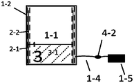
- Figure 1 is a schematic side view of the overall structure of a self-cleaning protection device for a liftable solar module of the present invention
- Fig. 2 is a schematic top view of the structure of a self-cleaning protection device for a liftable solar module of the present invention
- Fig. 3 is a schematic diagram of an automatic cleaning system of a liftable solar module self-cleaning protection device of the present invention
- Fig. 4 is a schematic diagram of the connection of the electric energy storage system of a self-cleaning protection device for a liftable solar module according to the present invention.
- Photovoltaic power generation body system 2. Fixed lifting system; 3. Shading and cleaning system; 4. Electric energy storage system; 1-1. Photovoltaic components for power generation components; 1-2. Metal frame; 1-4, DC line; 1-5 Inverter boost device; 2-1, U-shaped support side baffle; 2-2, slideway groove; 2-3, roller; 2-4, melting water source storage tank; 2-5, tablet pressing; 3-1, covering cloth; 3-2, cleaning subsystem; 3-3, rotating shaft; 3-4-1, lifting and stretching motor; 3-4-2, rotating shaft motor ; 4-1, energy storage battery; 4-2, relay.
- the present invention provides a liftable self-cleaning protection device for solar modules, including a photovoltaic power generation body system 1 , a fixed lifting system 2 , a shielding cleaning system 3 and an electric energy storage system 4 .
- Photovoltaic power generation body system 1 is used to convert solar energy into electric energy for grid-connected power generation or to provide electric energy for the energy storage electric system 4 of the device of the present invention
- a fixed lifting system 2 is arranged above the photovoltaic power generation body system 1 for fixing the entire shelter cleaning system 3, And drive the shielding and cleaning system 3 to lift, and provide clean water storage space at the same time
- the lower edge of the fixed lifting system 2 is provided with a shielding and cleaning system 3, which is used to reduce the impact of sand, dust, rain and snow on the photovoltaic power generation main system 1, and can also clean and generate electricity
- the surface of the body photovoltaic module 1-1; the input end of the electric energy storage system 4 is connected to the photovoltaic power generation body system 1, and the excess electric energy emitted by the power generation element photovoltaic module 1-1 is stored, and the output end is connected to each motor, and press
- the control command is the electric energy of each motor in the device.
- the photovoltaic power generation main system 1 includes a photovoltaic module 1-1 of a power generation element, a metal frame 1-2, a support and a foundation 1-3, a DC line 1-4, and an inverter booster device 1-5.
- the photovoltaic module 1-1 of the power generation element is wrapped and fixed by the metal frame 1-2, and is fixed above the bracket and the foundation 1-3; the output end of the photovoltaic module 1-1 of the power generation element is connected with the inverter booster device 1 through the DC line 1-4 -5 connected.
- the fixed lifting system 2 includes a U-shaped support side baffle 2-1, a slideway groove 2-2, a roller 2-3, a melting water source storage groove 2-4 and a pressing piece 2-5.
- the U-shaped support side baffle 2-1 includes two left-right symmetrical ones; the U-shaped support side baffle 2-1 is set on the metal frame 1-2 and is parallel to the photovoltaic module 1-1 of the power generation element, and the inclination angle of the two is the same ;
- the pressing sheet 2-5 installs each U-shaped support side baffle 2-1 on the metal frame 1-2, and the inside of the U-shaped side baffle 2-1 is provided with the U-shaped side baffle from the bottom to the
- the shielding cleaning system 3 includes a shielding cloth 3-1, a cleaning subsystem 3-2, a rotating shaft 3-3, a lifting and stretching motor 3-4-1 and a rotating shaft motor 3-4-2. Both sides of the upper edge of the shielding cloth 3-1 are connected with the roller 2-3 through buckles, and the lower edge is connected with the rotating shaft 3-3.
- the cleaning subsystem 3-2 is glued to the inside of the shielding cloth 3-1, and the rotating shaft 3-3 is installed Inside the melting water source storage tank 2-4, it is connected with the rotating shaft motor 3-4-2, and the top of the slideway groove 2-2 is provided with a lifting and stretching motor 3-4-1 that can be forward and reverse;
- the output end of the extension motor 3-4-1 is connected to the rope, and the other end of the rope is connected with the roller 2-3 by the rope, and its effect can drive the roller 2-3 to run.
- the electric energy storage system 4 includes an energy storage battery 4-1 and a relay 4-2.
- the relay 4-2 is connected between the inverter step-up device 1-5 and the photovoltaic module 1-1 of the power generation element, the output terminal of the energy storage battery 4-1 is connected with the lifting and stretching motor 3-4-1, and the rotating shaft motor 3- 4-2 connected.
- Photovoltaic power generation system 1 includes inverter and booster equipment 1-5, which is composed of a booster circuit and an inverter bridge circuit, which boosts the DC voltage output by the photovoltaic module 1-1 of the power generation element to the DC voltage required for inverter output control. Voltage, the inverter bridge circuit converts the boosted DC voltage equivalently into AC voltage of common frequency.
- the fixed lifting system 2 includes a melting water source storage tank 2-4, the upper edge of the melting water source storage tank 2-4 is set on the inner side below the U-shaped support side baffle 2-1, and the lower edge is set on the U-shaped support side baffle 2-1 outside.
- the masking cloth 3-1 of the masking and cleaning system 3 is composed of super-strength nylon cloth, and the cleaning subsystem 3-2 is composed of a soft brush and a polyvinyl alcohol surface mixed side by side.
- the cleaning subsystem The 3-2 hairbrush is rolled inwardly in the rotating shaft 3-3.
- the electric energy storage system 4 includes a power line controlled by the relay 4-2 to connect the photovoltaic module 1-1 of the power generation element and the energy storage battery 4-1, and the current transmission can be switched at any time by controlling the working switching state of the relay 4-2 in the background
- the circuit provides the electric energy produced by the photovoltaic module 1-1 of the power generation element to charge the energy storage battery 4-1.
- the present invention also provides a method for using the anti-pinch rope pulley device, comprising the following steps:
- Step 1 In the initial stage, the shielding cloth 3-1 and the cleaning subsystem 3-2 are all bent into rolls and placed on the rotating shaft 3-3, and the upper edge of the shielding cloth 3-1 is located at the lower edge of the photovoltaic module 1-1 of the power generation element.
- the energy storage battery 4-1 is controlled to supply positive power to the lifting and stretching motor 3-4-1, and the roller 2-3 is driven upward
- the upper edge of the shading cloth 3-1 moves upward; at the same time, the energy storage battery 4-1 supplies positive power to the rotating shaft motor 3-4-2, causing the rotating shaft 3-3 to rotate forward, so that the shielding cloth wound on the rotating shaft 3-3 Cloth 3-1 is gradually turned outward.
- the simultaneous action of the two can make the upper edge of the shielding cloth 3-1 reach the top of the upper edge of the metal frame 1-2.
- the energy storage battery 4-1 stops all power supply, and can lift and stretch the motor 3-4-1 and the rotating shaft motor. 3-4-2 stops working, and the rollers and rotating shafts also stop moving.
- the shielding cloth 3-1 is fully opened and laid flat on the photovoltaic module 1-1 of the power generation element;
- Step 2 After the bad weather, a little rain and snow left on the surface of the shielding cloth 3-1 will melt into water and flow into the melted water source storage tank 2-4 along the slope, and then enter the cleaning stage.
- Control the energy storage battery 4-1 to supply reverse power to the lifting and stretching motor 3-4-1, causing the roller 2-3 to drive down the upper edge of the shielding cloth 3-1;
- the motor 3-4-2 supplies reverse electricity, causing the rotating shaft 3-3 to reverse, so that the shielding cloth 3-1 is wound on the rotating shaft 3-3, and the two act simultaneously to make the shielding cloth 3-1 and the cleaning subsystem 3-2 All bent into rolls and placed on the rotating shaft 3-3 to stop, then the soft brush and polyvinyl alcohol surface of the cleaning subsystem 3-2 are all bent into rolls and placed on the rotating shaft 3-3, soaked It becomes wet in the rain and snow melting water.
- the energy storage battery 4-1 provides positive power to the liftable stretching motor 3-4-1 and the rotating shaft motor 3-4-2 through the control system, and drives the rotating shaft 3 at the same time. -3 forward rotation and pull roller 2-3 up.
- the two work together to make the shade cloth 3-1 move downward.
- the control program controls the motor to rotate forward, thereby realizing the shade cloth 3-1 and the cleaning subsystem 3-1. 2 Movement up and down.
- the cleaning subsystem 3-2 continuously cleans the electrical component photovoltaic module 1-1 until the cleaning subsystem 3-2 completes the cleaning of the power generation component photovoltaic module 1-1;
- Step 3 After cleaning, no matter where it is, the control system orders the energy storage battery 4-1 to supply reverse power to the lifting and stretching motor 3-4-1 and the rotating shaft motor 3-4-2.
- the shielding cloth 3-1 and the cleaning subsystem 3-2 are all bent into rolls and placed on the rotating shaft 3-3, thereby completing the retraction process of the shielding and cleaning system 3.
Landscapes
- Photovoltaic Devices (AREA)
Abstract
本发明公开了一种可升降式太阳能组件自清洁防护装置及使用方法;所述装置,包括光伏发电本体系统、固定升降系统、遮挡清洁系统和电动储能系统;所述光伏发电本体系统上方设有固定升降系统;所述电动储能系统的输入端与光伏发电本体系统的输出端相连;所述固定升降系统连接有遮挡清洁系统;所述挡清洁系统能够卷收放置于光伏发电本体系统旁侧。本装置运作时通过储能电池给电机供电,带动滚轮与转动轴运动,使遮挡布在雨雪、沙尘天气时起到遮挡作用,恶劣天气过后,反复在发电元件光伏组件表面运动起到自动清洁的效果。本发明具有无需人工现场操作、清洁效率快,清洁到位、节约能耗的特点。
Description
本发明属于新能源光伏发电应用领域,具体涉及一种可升降式太阳能组件自清洁防护装置及使用方法。
能源是现代社会存在和发展的基石。随着全球经济社会的不断发展,能源消费也相应的持续增长,但是化石能源是不可再生的,所以,在化石能源供应日趋紧张的背景下,大规模的开发和利用可再生能源已成为未来各国能源战略中的重要组成部分。在风能,水利能,潮汐能,太阳能等各种新型清洁能源中,因为储量大,世界公认都对太阳能更青睐有加有加。进到二十一世纪,太阳能电池板向全世界拓展,变成一种关键的可再生资源。随着全世界光伏发电综合利用经营规模快速扩张,技术性不断发展,成本费明显减少,呈现出优良的发展前途,我国将光伏发电做为关键的新型产业,光伏发电获得更为广泛运用。2001年至2020年间,光伏产业以令大家惊讶的速率往前发展趋势。全世界总计装机容积自1,250MW升至707490MW,年复合增长率达到39.6%。
由于光伏发电依靠太阳光照射,发电的效率很大程度上取决于电池板的洁净程度。然而无论是西北地区的地面光伏电站,还是东部地区的屋顶电站,光伏组件被污染物所覆盖,严重影响了发电量,且酸碱性灰尘粘结在光伏板上还将腐蚀玻璃盖板,对光伏板会造成不可逆转的损害,长期降低光伏组件的转化效率和使用寿命。
现有清雪清灰常用方法还是采用人工除雪除灰的方式,该方式存在操作强度高、工作环境恶劣、清洁效率慢且不到位,清洁过程中损坏组件的问题。
发明内容
本发明的目在于提供一种可升降式太阳能组件自清洁防护装置及使用方法,以解决因恶劣天气导致污染物堆积在发电元件光伏组件上没能及时清理对发电元件光伏组件造成的损害。
为了实现上述目的,本发明通过以下技术方案实现:
一种可升降式太阳能组件自清洁防护装置,包括光伏发电本体系统、固定升降系统、遮挡清洁系统和电动储能系统;所述光伏发电本体系统上方设有固定升降系统;所述电动储能系统的输入端与光伏发电本体系统的输出端相连;所述固定升降系统连接有遮挡清洁系统;所述挡清洁系统能够卷收放置于光伏发电本体系统旁侧。
本发明进一步的改进在于:所述光伏发电本体系统包括发电元件光伏组件、金属边框、支架与基础、直流线路和逆变升压设备,所述支架与基础上方设有发电元件光伏组件,所述发电元件光伏组件被金属边框包裹固定,所述发电元件光伏组件通过直流线路与逆变升压设备相连。
本发明进一步的改进在于:所述固定升降系统包含U型支撑侧挡板和滚轮;所述U型支撑侧挡板包含左右对称设置的两个;两个U型支撑侧挡板固定设置在金属边框上;U型支撑侧挡板的内部设有沿着U型侧挡板从底端到顶端的滑道槽,所述滑道槽中安装有滚轮。
本发明进一步的改进在于:所述遮挡清洁系统包含遮挡布、转动轴、可升降拉伸电机和转动轴电机,所述遮挡布上沿两侧与滚轮穿扣相连,下沿与转动轴相连,所述清洁子系统粘在遮挡布的内部,所述转动轴位于发电元件光伏组件下方且与转动轴电机相连,所述滑道槽的顶端设有一台能够正反转的可升降拉伸电机;可升降拉伸电机输出端连接绳子,绳子另一端与滚轮相连;所述可升降拉伸电机能够带动滚轮运行。
本发明进一步的改进在于:所述电动储能系统包含储能电池、继电器,所述继电器连接在逆变升压设备与发电元件光伏组件之间,所述储能电池输出端与可升降拉伸电机、转动轴电机相连。
本发明进一步的改进在于:所述固定升降系统还包括融化水源收纳槽,所述融化水源收纳槽里端设置在U型支撑侧挡板下方靠内侧,外端设置在U型支撑侧挡板外侧。
本发明进一步的改进在于:所述遮挡布为尼龙布。
本发明进一步的改进在于:所述清洁子系统由毛刷与聚乙烯醇胶面并排混合组成。
一种可升降式太阳能组件自清洁防护装置的使用方法,包括以下步骤:
步骤一:遮挡布上行带动遮挡布上沿上行;同时储能电池给转动轴电机上的遮挡布逐渐外翻出去,使遮挡布上沿到达金属边框停止所有供电,可升降拉伸电机完全打开,平铺在发电元件光伏组件上方;
步骤二:遮挡布下行带动遮挡布上沿下行;同时储能电池给转动轴电机反转,使遮挡布卷在转动轴上,使遮挡布向上运动,在将要达到发电元件光伏组件上沿处时,控制储能电池反转以及拉动滚轮下行,使遮挡布进行清洁;
步骤三:当清洁完毕后,控制储能电池给可升降拉伸电机、转动轴电机供反向电,使遮挡布和清洁子系统全部弯曲成卷收放在转动轴上。
与现有技术相比,本发明具有以下有益效果:
1、本发明一种可升降式太阳能组件自清洁防护装置,保证了发电元件光伏组件长时间不受恶劣天气的影响,提高发电元件光伏组件寿命,提升全生命周期发电量,具有很好的经济性。
2、本装置同时实现了发电元件光伏组件的防护与清洁功能,减少了购买维护设备费用支出。
3、本发明连同带有自动清洁功能,利用已有的雨雪资源,节省资源利用。
4、本装置电能全部来自于清洁能源光伏发电系统中,很好地解决了自身消纳问题,且具有环保属性。
5、免去人工现场检查清理维护,降低运维人员成本。
构成本发明的一部分的说明书附图用来提供对本发明的进一步理解,本发明的示意性实施例及其说明用于解释本发明,并不构成对本发明的不当限定。在附图中:
图1为本发明一种可升降式太阳能组件自清洁防护装置整体结构侧视示意图;
图2为本发明一种可升降式太阳能组件自清洁防护装置结构俯视示意图;
图3为本发明一种可升降式太阳能组件自清洁防护装置自动清洁系统示意图;
图4为本发明一种可升降式太阳能组件自清洁防护装置电能储能系统连接示意图。
1、光伏发电本体系统;2、固定升降系统;3、遮挡清洁系统;4、电动储能系统;1-1、发电元件光伏组件;1-2、金属边框;1-3、支架与基础;1-4、直流线路;1-5逆变升压设;2-1、U型支撑侧挡板;2-2、滑道槽;2-3、滚轮;2-4、融化水源收纳槽;2-5、压片;3-1、遮挡布;3-2、清洁子系统;3-3、转动轴;3-4-1、可升降拉伸电机;3-4-2、转动轴电机;4-1、储能电池;4-2、继电器。
下面将参考附图并结合实施例来详细说明本发明。需要说明的是,在不冲突的情况下,本发明中的实施例及实施例中的特征可以相互组合。
以下详细说明均是示例性的说明,旨在对本发明提供进一步的详细说明。除非另有指明,本发明所采用的所有技术术语与本发明所属领域的一般技术人员的通常理解的含义相同。本发明所使用的术语仅是为了描述具体实施方式,而并非意图限制根据本发明的示例性实施方式。
参照附图1-4,本发明提供一种可升降式太阳能组件自清洁防护装置,包括光伏发电本体系统1、固定升降系统2、遮挡清洁系统3和电动储能系统4。
光伏发电本体系统1用于将太阳能转化为电能并网发电或为本发明装置储能电动系统4提供电能;光伏发电本体系统1上方设有固定升降系统2,用于固定整个遮挡清洁系统3,以 及带动遮挡清洁系统3升降,同时提供清洁水源存储空间;固定升降系统2下边缘设置有遮挡清洁系统3,用于减少沙尘、雨雪天气对光伏发电本体系统1的影响,还可清洗发电本体光伏组件1-1表面;电动储能系统4输入端与光伏发电本体系统1相连,将发电元件光伏组件1-1发出多余不能消纳的电能进行存储,输出端与各电机相连,并按控制指令为装置中各电机电能。
光伏发电本体系统1包括发电元件光伏组件1-1、金属边框1-2、支架与基础1-3、直流线路1-4和逆变升压设备1-5。发电元件光伏组件1-1被金属边框1-2包裹固定,并固定在支架与基础1-3上方;发电元件光伏组件1-1的输出端通过直流线路1-4与逆变升压设备1-5相连。
固定升降系统2包括U型支撑侧挡板2-1、滑道槽2-2、滚轮2-3、融化水源收纳槽2-4和压片2-5。U型支撑侧挡板2-1包含左右对称的两个;U型支撑侧挡板2-1设置在金属边框1-2上与且与发电元件光伏组件1-1平行,二者倾角角度一致;压片2-5将每个U型支撑侧挡板2-1安装在金属边框1-2上,U型侧挡板2-1的内部设有沿着U型侧挡板从底端到顶端的滑道槽2-2,滑道槽2-2中安装有滚轮2-3,融化水源收纳槽2-4里端设置在U型支撑侧挡板2-1下方靠内侧,外端设置在U型支撑侧挡板2-1外侧。
遮挡清洁系统3包含遮挡布3-1、清洁子系统3-2、转动轴3-3、可升降拉伸电机3-4-1和转动轴电机3-4-2。遮挡布3-1上沿两侧与滚轮2-3穿扣相连,下沿与转动轴3-3相连,清洁子系统3-2粘在遮挡布3-1的内部,转动轴3-3安装在融化水源收纳槽2-4内部与转动轴电机3-4-2相连,滑道槽2-2的顶端设有一台可正反转的可升降拉伸电机3-4-1;可升降拉伸电机3-4-1输出端连接绳子,绳子另一端与滚轮2-3通过绳子相连,其作用能够带动滚轮2-3运行。
电动储能系统4包含储能电池4-1、继电器4-2。继电器4-2连接在逆变升压设备1-5与发电元件光伏组件1-1之间,储能电池4-1输出端与可升降拉伸电机3-4-1、转动轴电机3-4-2相连。
光伏发电本体系统1包括逆变升压设备1-5由升压回路以及逆变桥式回路构成,把发电元 件光伏组件1-1输出的直流电压升压到逆变器输出控制所需的直流电压,逆变桥式回路则把升压后的直流电压等价地转换成常用频率的交流电压。
固定升降系统2包括融化水源收纳槽2-4,融化水源收纳槽2-4上沿设置在U型支撑侧挡板2-1下方靠内侧,下沿设置在U型支撑侧挡板2-1外侧。
遮挡清洁系统3的遮挡布3-1由超强度尼龙布组成,清洁子系统3-2由柔软的毛刷与聚乙烯醇胶面并排混合组成,遮挡布3-1不工作时,清洁子系统3-2毛刷向内卷在转动轴3-3中。
电动储能系统4包括一条被继电器4-2控制连接发电元件光伏组件1-1与储能电池4-1相连的电力线路,通过后台控制继电器4-2的工作切换状态,可随时切换电流输送线路,将发电元件光伏组件1-1产出的电能提供给储能电池4-1充电。
本发明还提供一种防夹绳滑轮装置的使用方法,包括以下步骤:
步骤一:初始阶段遮挡布3-1和清洁子系统3-2全部弯曲成卷收放在转动轴3-3上,遮挡布3-1上沿位于发电元件光伏组件1-1下沿处。当天气恶劣,需要启动该装置为发电元件光伏组件1-1提供防护时,控制储能电池4-1给可升降拉伸电机3-4-1供正向电,带动滚轮2-3上行带动遮挡布3-1上沿上行;同时储能电池4-1给转动轴电机3-4-2供正向电,导致转动轴3-3正转,使卷在转动轴3-3上的遮挡布3-1逐渐外翻出去。二者同时作用可使遮挡布3-1上沿到达金属边框1-2上沿的上方,此时储能电池4-1停止所有供电,可升降拉伸电机3-4-1、转动轴电机3-4-2停止工作,滚轮和转动轴也停止运动,此时遮挡布3-1完全打开,平铺在发电元件光伏组件1-1上方;
步骤二:当恶劣天气过后,遮挡布3-1表面遗留少许雨雪会融为水顺斜面流入融化水源收纳槽2-4中,此时进入清洁阶段。控制储能电池4-1给可升降拉伸电机3-4-1供反向电,导致滚轮2-3下行带动遮挡布3-1上沿下行;同时储能电池4-1也给转动轴电机3-4-2供反向电,导致转动轴3-3反转,使遮挡布3-1卷在转动轴3-3上,二者同时作用可使遮挡布3-1和清洁 子系统3-2全部弯曲成卷收放在转动轴3-3上停止,则清洁子系统3-2柔软的毛刷与聚乙烯醇胶面全部弯曲成卷收放在转动轴3-3中,浸泡在雨雪融化水中变湿润,清洗时通过控制系统给储能电池4-1给可升降拉伸电机3-4-1、转动轴电机3-4-2提供正向电,同时带动转动轴3-3正转以及拉动滚轮2-3上行。二者共同作用使遮挡布3-1向上运动,在将要达到发电元件光伏组件1-1上沿处时,控制储能电池4-1给可升降拉伸电机3-4-1、转动轴电机3-4-2供反向电,同时带动转动轴3-3反转以及拉动滚轮2-3下行。二者共同作用使遮挡布3-1向下运动,在将要达到发电元件光伏组件1-1下沿处时,控制程序再控制电机正转,从而实现遮挡布3-1与清洁子系统3-2上下来回运动。重复上述过程,清洁子系统3-2不断清洁电元件光伏组件1-1,直到清洁子系统3-2完成对发电元件光伏组件1-1的清洁;
步骤三:当清洁完毕后,不管在任何位置,控制系统下命令让储能电池4-1给可升降拉伸电机3-4-1、转动轴电机3-4-2供反向电,可使遮挡布3-1和清洁子系统3-2全部弯曲成卷收放在转动轴3-3上,从而完成遮挡清洁系统3的收回过程。
由技术常识可知,本发明可以通过其它的不脱离其精神实质或必要特征的实施方案来实现。因此,上述公开的实施方案,就各方面而言,都只是举例说明,并不是仅有的。所有在本发明范围内或在等同于本发明的范围内的改变均被本发明包含。
Claims (9)
- 一种可升降式太阳能组件自清洁防护装置,其特征在于,包括光伏发电本体系统(1)、固定升降系统(2)、遮挡清洁系统(3)和电动储能系统(4);所述光伏发电本体系统(1)上方设有固定升降系统(2);所述电动储能系统(4)的输入端与光伏发电本体系统(1)的输出端相连;所述固定升降系统(2)连接有遮挡清洁系统(3);所述挡清洁系统(3)能够卷收放置于光伏发电本体系统(1)旁侧。
- 根据权利要求1所述的一种可升降式太阳能组件自清洁防护装置,其特征在于,所述光伏发电本体系统(1)包括发电元件光伏组件(1-1)、金属边框(1-2)、支架与基础(1-3)、直流线路(1-4)和逆变升压设备(1-5),所述支架与基础(1-3)上方设有发电元件光伏组件(1-1),所述发电元件光伏组件(1-1)被金属边框(1-2)包裹固定,所述发电元件光伏组件(1-1)通过直流线路(1-4)与逆变升压设备(1-5)相连。
- 根据权利要求2所述的一种可升降式太阳能组件自清洁防护装置,其特征在于,所述固定升降系统(2)包含U型支撑侧挡板(2-1)和滚轮(2-3);所述U型支撑侧挡板(2-1)包含左右对称设置的两个;两个U型支撑侧挡板(2-1)固定设置在金属边框(1-2)上;U型支撑侧挡板(2-1)的内部设有沿着U型侧挡板从底端到顶端的滑道槽(2-2),所述滑道槽(2-2)中安装有滚轮(2-3)。
- 根据权利要求3所述的一种可升降式太阳能组件自清洁防护装置,其特征在于,所述遮挡清洁系统(3)包含遮挡布(3-1)、清洁子系统(3-2)、转动轴(3-3)、可升降拉伸电机(3-4-1)和转动轴电机(3-4-2),所述遮挡布(3-1)上沿两侧与滚轮(2-3)穿扣相连,下沿与转动轴(3-3)相连,所述清洁子系统(3-2)粘在遮挡布(3-1)的内部,所述转动轴(3-3)位于发电元件光伏组件(1-1)下方且与转动轴电机(3-4-2)相连,所述滑道槽(2-2)的顶端设有一台能够正反转的可升降拉伸电机(3-4-1);可升降拉伸电机(3-4-1)输出端连接绳子,绳子另一端与滚轮(2-3)相连;所述可升降拉伸电机(3-4-1)能够带动滚轮(2-3) 运行。
- 根据权利要求4所述的一种可升降式太阳能组件自清洁防护装置,其特征在于,所述电动储能系统(4)包含储能电池(4-1)、继电器(4-2),所述继电器(4-2)连接在逆变升压设备(1-5)与发电元件光伏组件(1-1)之间,所述储能电池(4-1)输出端与可升降拉伸电机(3-4-1)、转动轴电机(3-4-2)相连。
- 根据权利要求3所述的一种可升降式太阳能组件自清洁防护装置,其特征在于,所述固定升降系统(2)还包括融化水源收纳槽(2-4),所述融化水源收纳槽(2-4)里端设置在U型支撑侧挡板(2-1)下方靠内侧,外端设置在U型支撑侧挡板(2-1)外侧。
- 根据权利要求4所述的一种可升降式太阳能组件自清洁防护装置,其特征在于,所述遮挡布(3-1)为尼龙布。
- 根据权利要求7所述的一种可升降式太阳能组件自清洁防护装置,其特征在于,所述清洁子系统(3-2)由毛刷与聚乙烯醇胶面并排混合组成。
- 一种可升降式太阳能组件自清洁防护装置的使用方法,其特征在于,包括以下步骤:步骤一:遮挡布(3-1)和清洁子系统(3-2)全部弯曲成卷收放在转动轴(3-3)中,遮挡布(3-1)上沿位于发电元件光伏组件(1-1)下沿处;控制储能电池(4-1)给可升降拉伸电机(3-4-1)供正向电,使滚轮(2-3)上行带动遮挡布(3-1)上沿上行;同时储能电池(4-1)给转动轴电机(3-4-2)供正向电,使转动轴(3-3)正转,使卷在转动轴(3-3)上的遮挡布(3-1)逐渐外翻出去,使遮挡布(3-1)上沿到达金属边框(1-2)上沿的上方,此时储能电池(4-1)停止所有供电,可升降拉伸电机(3-4-1)、转动轴电机(3-4-2)停止工作,遮挡布(3-1)完全打开,平铺在发电元件光伏组件(1-1)上方;步骤二:遮挡布(3-1)表面遗留雨雪融化成水顺斜面流入融化水源收纳槽(2-4)中,控制储能电池(4-1)给可升降拉伸电机(3-4-1)供反向电,使滚轮(2-3)下行带动遮挡布(3-1) 上沿下行;同时储能电池(4-1)给转动轴电机(3-4-2)供反向电,使转动轴(3-3)反转,使遮挡布(3-1)卷在转动轴(3-3)上,使遮挡布(3-1)和清洁子系统(3-2)全部弯曲成卷收放在转动轴(3-3)上时停止;清洁子系统(3-2)的毛刷与聚乙烯醇胶面全部弯曲成卷收放在转动轴(3-3)中,浸泡在雨雪融化水中;清洗时控制储能电池(4-1)给可升降拉伸电机(3-4-1)、转动轴电机(3-4-2)提供正向电,同时带动转动轴(3-3)正转以及拉动滚轮(2-3)上行,使遮挡布(3-1)向上运动,在将要达到发电元件光伏组件(1-1)上沿处时,控制储能电池(4-1)给可升降拉伸电机(3-4-1)、转动轴电机(3-4-2)供反向电,同时带动转动轴(3-3)反转以及拉动滚轮(2-3)下行,使遮挡布(3-1)向下运动;重复上述过程,控制清洁子系统(3-2)上下往复运动,对发电元件光伏组件(1-1)进行清洁;步骤三:当清洁完毕后,控制储能电池(4-1)给可升降拉伸电机(3-4-1)、转动轴电机(3-4-2)供反向电,使遮挡布(3-1)和清洁子系统(3-2)全部弯曲成卷收放在转动轴(3-3)上。
Applications Claiming Priority (2)
| Application Number | Priority Date | Filing Date | Title |
|---|---|---|---|
| CN202110513428.6A CN113067541A (zh) | 2021-05-11 | 2021-05-11 | 一种可升降式太阳能组件自清洁防护装置及使用方法 |
| CN202110513428.6 | 2021-05-11 |
Publications (1)
| Publication Number | Publication Date |
|---|---|
| WO2022237005A1 true WO2022237005A1 (zh) | 2022-11-17 |
Family
ID=76568728
Family Applications (1)
| Application Number | Title | Priority Date | Filing Date |
|---|---|---|---|
| PCT/CN2021/114961 WO2022237005A1 (zh) | 2021-05-11 | 2021-08-27 | 一种可升降式太阳能组件自清洁防护装置及使用方法 |
Country Status (2)
| Country | Link |
|---|---|
| CN (1) | CN113067541A (zh) |
| WO (1) | WO2022237005A1 (zh) |
Cited By (2)
| Publication number | Priority date | Publication date | Assignee | Title |
|---|---|---|---|---|
| CN116827251A (zh) * | 2023-06-20 | 2023-09-29 | 佛山市博蔚金属制品有限公司 | 一种具有自清洁功能的光伏板支架及其使用方法 |
| CN117200679A (zh) * | 2023-09-13 | 2023-12-08 | 宁夏新三思检测设备有限公司 | 基于光伏建筑一体化光伏储能装置 |
Families Citing this family (1)
| Publication number | Priority date | Publication date | Assignee | Title |
|---|---|---|---|---|
| CN113067541A (zh) * | 2021-05-11 | 2021-07-02 | 中国华能集团清洁能源技术研究院有限公司 | 一种可升降式太阳能组件自清洁防护装置及使用方法 |
Citations (10)
| Publication number | Priority date | Publication date | Assignee | Title |
|---|---|---|---|---|
| CN201256153Y (zh) * | 2008-09-08 | 2009-06-10 | 动力新跃(北京)汽车科技有限公司 | 带有洁尘防护装置的太阳能电池板 |
| JP2014194994A (ja) * | 2013-03-29 | 2014-10-09 | Kowa Co Ltd | 着脱式ソーラーパネル清掃装置 |
| CN208257754U (zh) * | 2018-06-12 | 2018-12-18 | 湖北金索兰太阳能有限公司 | 一种多功能光伏发电装置 |
| CN110523678A (zh) * | 2019-09-15 | 2019-12-03 | 宁波润爵科技有限公司 | 一种太阳能电池板的清洗装置 |
| CN210041702U (zh) * | 2019-06-26 | 2020-02-07 | 贵州以光黔城科技有限公司 | 一种拥有自清洁功能的太阳能光伏板 |
| CN111313821A (zh) * | 2020-03-04 | 2020-06-19 | 湖南城市学院 | 一种自清洁降温型光伏发电装置 |
| CN210839424U (zh) * | 2019-11-23 | 2020-06-23 | 南京市第二建筑设计院有限公司 | 公共建筑光伏发电与建筑遮阳一体化支架 |
| CN112039418A (zh) * | 2020-09-03 | 2020-12-04 | 安徽恩吉光电股份有限公司 | 一种具有防雨功能的光伏发电设备 |
| CN113067541A (zh) * | 2021-05-11 | 2021-07-02 | 中国华能集团清洁能源技术研究院有限公司 | 一种可升降式太阳能组件自清洁防护装置及使用方法 |
| CN214756215U (zh) * | 2021-05-11 | 2021-11-16 | 中国华能集团清洁能源技术研究院有限公司 | 一种可升降式太阳能组件自清洁防护装置 |
-
2021
- 2021-05-11 CN CN202110513428.6A patent/CN113067541A/zh active Pending
- 2021-08-27 WO PCT/CN2021/114961 patent/WO2022237005A1/zh active Application Filing
Patent Citations (10)
| Publication number | Priority date | Publication date | Assignee | Title |
|---|---|---|---|---|
| CN201256153Y (zh) * | 2008-09-08 | 2009-06-10 | 动力新跃(北京)汽车科技有限公司 | 带有洁尘防护装置的太阳能电池板 |
| JP2014194994A (ja) * | 2013-03-29 | 2014-10-09 | Kowa Co Ltd | 着脱式ソーラーパネル清掃装置 |
| CN208257754U (zh) * | 2018-06-12 | 2018-12-18 | 湖北金索兰太阳能有限公司 | 一种多功能光伏发电装置 |
| CN210041702U (zh) * | 2019-06-26 | 2020-02-07 | 贵州以光黔城科技有限公司 | 一种拥有自清洁功能的太阳能光伏板 |
| CN110523678A (zh) * | 2019-09-15 | 2019-12-03 | 宁波润爵科技有限公司 | 一种太阳能电池板的清洗装置 |
| CN210839424U (zh) * | 2019-11-23 | 2020-06-23 | 南京市第二建筑设计院有限公司 | 公共建筑光伏发电与建筑遮阳一体化支架 |
| CN111313821A (zh) * | 2020-03-04 | 2020-06-19 | 湖南城市学院 | 一种自清洁降温型光伏发电装置 |
| CN112039418A (zh) * | 2020-09-03 | 2020-12-04 | 安徽恩吉光电股份有限公司 | 一种具有防雨功能的光伏发电设备 |
| CN113067541A (zh) * | 2021-05-11 | 2021-07-02 | 中国华能集团清洁能源技术研究院有限公司 | 一种可升降式太阳能组件自清洁防护装置及使用方法 |
| CN214756215U (zh) * | 2021-05-11 | 2021-11-16 | 中国华能集团清洁能源技术研究院有限公司 | 一种可升降式太阳能组件自清洁防护装置 |
Cited By (4)
| Publication number | Priority date | Publication date | Assignee | Title |
|---|---|---|---|---|
| CN116827251A (zh) * | 2023-06-20 | 2023-09-29 | 佛山市博蔚金属制品有限公司 | 一种具有自清洁功能的光伏板支架及其使用方法 |
| CN116827251B (zh) * | 2023-06-20 | 2024-03-08 | 佛山市博蔚金属制品有限公司 | 一种具有自清洁功能的光伏板支架及其使用方法 |
| CN117200679A (zh) * | 2023-09-13 | 2023-12-08 | 宁夏新三思检测设备有限公司 | 基于光伏建筑一体化光伏储能装置 |
| CN117200679B (zh) * | 2023-09-13 | 2024-04-26 | 青海民族大学 | 基于光伏建筑一体化光伏储能装置 |
Also Published As
| Publication number | Publication date |
|---|---|
| CN113067541A (zh) | 2021-07-02 |
Similar Documents
| Publication | Publication Date | Title |
|---|---|---|
| WO2022237005A1 (zh) | 一种可升降式太阳能组件自清洁防护装置及使用方法 | |
| CN202479185U (zh) | 太阳能电池板自动清扫装置 | |
| CN110729959A (zh) | 一种防积尘积水及无遮挡带支撑式自清洗光伏组件 | |
| CN104722510A (zh) | 一种太阳能电池板智能除尘装置 | |
| CN205056510U (zh) | 一种全天候光伏太阳能电池板清扫机器人 | |
| CN111446916A (zh) | 一种抗辐射式的分布光伏发电装置 | |
| CN204159569U (zh) | 光伏农业大棚组件横向清洗装置 | |
| CN214756215U (zh) | 一种可升降式太阳能组件自清洁防护装置 | |
| CN114383098A (zh) | 一种具有清洁灰尘功能的节能型智慧城市照明装置 | |
| CN207350006U (zh) | 一种太阳能路灯 | |
| CN206922707U (zh) | 光伏发电电池板清扫装置 | |
| CN108532991B (zh) | 一种具有防雨功能的节能环保新能源公交站台 | |
| CN114465570B (zh) | 一种建筑屋顶光伏发电板的冷却清洁和可拆卸安装装置及方法 | |
| CN113054900A (zh) | 一种太阳能组件保护清洁一体装置及其工作方法 | |
| CN202955603U (zh) | 风光互补路灯 | |
| CN212811629U (zh) | 一种带有自清洁装置的新能源光伏 | |
| CN212703235U (zh) | 一种便携式移动清洗机器人 | |
| CN212584845U (zh) | 一种遮雨用多功能太阳能路灯 | |
| CN204145387U (zh) | 一种太阳能电池板的综合清洗装置 | |
| CN214851117U (zh) | 一种太阳能组件保护清洁一体装置 | |
| CN207662002U (zh) | 一种太阳能蓄能转换器 | |
| CN202013896U (zh) | 太阳能电池组件表面清洗装置 | |
| CN216599505U (zh) | 定时自动转动的路灯用太阳能电池板 | |
| CN219717528U (zh) | 一种光伏电站升压站外部防晒结构 | |
| CN213927709U (zh) | 一种可智能清洗的电动汽车光伏发电车棚 |
Legal Events
| Date | Code | Title | Description |
|---|---|---|---|
| 121 | Ep: the epo has been informed by wipo that ep was designated in this application |
Ref document number: 21941572 Country of ref document: EP Kind code of ref document: A1 |
|
| NENP | Non-entry into the national phase |
Ref country code: DE |
|
| 122 | Ep: pct application non-entry in european phase |
Ref document number: 21941572 Country of ref document: EP Kind code of ref document: A1 |