WO2022234825A1 - Insulating structure for multiphase motor, and multiphase motor - Google Patents
Insulating structure for multiphase motor, and multiphase motor Download PDFInfo
- Publication number
- WO2022234825A1 WO2022234825A1 PCT/JP2022/019378 JP2022019378W WO2022234825A1 WO 2022234825 A1 WO2022234825 A1 WO 2022234825A1 JP 2022019378 W JP2022019378 W JP 2022019378W WO 2022234825 A1 WO2022234825 A1 WO 2022234825A1
- Authority
- WO
- WIPO (PCT)
- Prior art keywords
- coil
- stator
- connector
- phase
- multiphase
- Prior art date
Links
- 238000009413 insulation Methods 0.000 claims abstract description 31
- 239000011810 insulating material Substances 0.000 claims abstract description 15
- WABPQHHGFIMREM-UHFFFAOYSA-N lead(0) Chemical compound [Pb] WABPQHHGFIMREM-UHFFFAOYSA-N 0.000 description 6
- 238000000034 method Methods 0.000 description 4
- 239000011248 coating agent Substances 0.000 description 3
- 238000000576 coating method Methods 0.000 description 3
- 230000000694 effects Effects 0.000 description 3
- 230000007935 neutral effect Effects 0.000 description 3
- 230000002093 peripheral effect Effects 0.000 description 3
- 238000010586 diagram Methods 0.000 description 2
- 238000004519 manufacturing process Methods 0.000 description 2
- 239000000843 powder Substances 0.000 description 2
- 238000003466 welding Methods 0.000 description 2
- 229910000831 Steel Inorganic materials 0.000 description 1
- 238000001514 detection method Methods 0.000 description 1
- 239000000463 material Substances 0.000 description 1
- 230000007246 mechanism Effects 0.000 description 1
- 238000000465 moulding Methods 0.000 description 1
- 239000011347 resin Substances 0.000 description 1
- 229920005989 resin Polymers 0.000 description 1
- 239000010959 steel Substances 0.000 description 1
Images


Classifications
-
- H—ELECTRICITY
- H02—GENERATION; CONVERSION OR DISTRIBUTION OF ELECTRIC POWER
- H02K—DYNAMO-ELECTRIC MACHINES
- H02K3/00—Details of windings
- H02K3/46—Fastening of windings on the stator or rotor structure
- H02K3/50—Fastening of winding heads, equalising connectors, or connections thereto
-
- H—ELECTRICITY
- H02—GENERATION; CONVERSION OR DISTRIBUTION OF ELECTRIC POWER
- H02K—DYNAMO-ELECTRIC MACHINES
- H02K5/00—Casings; Enclosures; Supports
- H02K5/04—Casings or enclosures characterised by the shape, form or construction thereof
- H02K5/22—Auxiliary parts of casings not covered by groups H02K5/06-H02K5/20, e.g. shaped to form connection boxes or terminal boxes
- H02K5/225—Terminal boxes or connection arrangements
-
- H—ELECTRICITY
- H02—GENERATION; CONVERSION OR DISTRIBUTION OF ELECTRIC POWER
- H02K—DYNAMO-ELECTRIC MACHINES
- H02K2203/00—Specific aspects not provided for in the other groups of this subclass relating to the windings
- H02K2203/09—Machines characterised by wiring elements other than wires, e.g. bus rings, for connecting the winding terminations
Definitions
- the present disclosure relates to an insulation structure for a polyphase motor and a polyphase motor.
- a stator used in a rotating electrical machine disclosed in Patent Document 1 includes a stator section and segment coils wound around the stator section.
- the segment coil is configured as a three-phase segment coil.
- the segment coil has a coil end projecting from the stator core to one side in the axial direction.
- the coil ends are insulated with powder.
- One object of the present disclosure is to easily ensure the insulation of a plurality of coil ends.
- An insulation structure used for a multiphase motor which is one of the present disclosure, Used in a multi-phase motor having a stator section, in which a stator core and a multi-phase coil are provided in the stator section, A covering portion is provided which covers together a plurality of coil ends protruding from the end portion of the stator core in the multiphase coil, defines and holds the positional relationship of the plurality of coil ends, and includes an insulating material.
- a polyphase motor which is one of the present disclosure, uses the above insulation structure for a polyphase motor.
- the present disclosure can easily ensure the insulation of a plurality of coil ends.
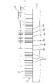
- FIG. 1 is an exploded perspective view of a motor according to a first embodiment of the present disclosure
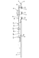
- FIG. FIG. 4 is a perspective view showing a stator section to which a rotation angle sensor and a connector are assembled
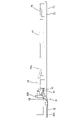
- FIG. 3 is a side view showing part of the rotation angle sensor, connector, and stator shown in FIG. 2
- FIG. 3 is a side cross-sectional view showing the rotation angle sensor, connector, and stator shown in FIG. 2
- FIG. 4 is a perspective view of the connector viewed from one side in the axial direction
- FIG. 4 is a perspective view of the connector as seen from the other side in the axial direction
- It is a top view of a connection connector.
- It is a side view of a connection connector.
- FIG. 9 is a side view of the connector viewed from a direction different from that of FIG. 8; It is an explanatory view explaining a flow of an assembly process of a motor.
- FIG. 11 is an explanatory diagram illustrating the flow of the motor assembly process following FIG. 10 ;
- a multi-phase coil comprising: a covering portion that collectively covers a plurality of coil ends protruding from an end portion of the stator core in the multiphase coil, holds a positional relationship between the plurality of coil ends, and includes an insulating material. Insulation structure for phase motors.
- the covering section is configured to determine and hold the positional relationship of the plurality of coil ends, so that it can be assembled to the plurality of coil ends collectively.
- the covering portion includes an insulating material and is configured to collectively cover the plurality of coil ends, the insulation of the plurality of coil ends can be ensured. Therefore, the insulation structure for a polyphase motor can easily ensure the insulation of the plurality of coil ends by covering the end portion side of the stator core with the covering portion.
- the covering portion may be annularly provided along the annular end portion of the stator core. With this configuration, the covering portion can be stably fixed to the stator portion.
- the insulating structure for a polyphase motor may have a terminal holding portion that holds a plurality of power terminals electrically connected to the polyphase coils and that includes an insulating material.
- the terminal holding portion may be attached to the covering portion.
- the insulating structure for a polyphase motor can function as a holding structure for the power terminals.
- the terminal holding portion may be connected to a connector on the output side of the inverter.
- the power terminal and the output terminal of the inverter may be electrically connected. According to this configuration, since the terminal holding portion holding the power terminals is connected to the connector on the output side of the inverter, the number of mechanisms for holding the power terminals between the polyphase motor and the inverter can be reduced.
- a conductive portion that connects the first-phase coil portion, the second-phase coil portion, and the third-phase coil portion in parallel is integrated with the covering portion.
- the covering portion can function to hold the conductive portion, and the conductive portion can be incorporated into the insulating structure for the multiphase motor.
- the covering portion may be detachable from the stator portion.
- the coil end 38 can be easily insulated compared to a configuration in which the insulating member cannot be attached to or detached from the stator portion by welding or the like.
- a polyphase motor according to the present disclosure uses the insulation structure for a polyphase motor according to any one of [1] to [6]. According to this configuration, it is possible to realize a polyphase motor having the same effect as any one of [1] to [6].
- the motor 10 of the first embodiment is a multiphase motor that utilizes a multiphase AC power supply.
- the motor 10 includes a housing 11, an end cover 13, a stator portion 21, a rotor portion 23, a connector 25, a rotation angle sensor 27, and a flange 29, as shown in FIG.
- the "polyphase motor insulation structure" of the present invention is an insulation structure used in the motor 10, and is applied to the connector 25 as an example.
- the housing 11 has a bottomed cylindrical shape with an opening at one end in the axial direction.
- the end cover 13 is attached to the housing 11 so as to close the opening of the housing 11 .
- a stator portion 21 , a rotor portion 23 , a connector 25 , a rotation angle sensor 27 and a flange 29 are accommodated in the housing 11 .
- the housing 11 is provided with a connection opening 11A through which power terminals 41A, 42A, 43A and a socket 77 of a connector 25, which will be described later, are exposed.
- the rotation angle sensor 27 is connected to the connector 25 via the sensor connector 28 .
- the stator portion 21 is fixed inside the housing 11 .
- the rotor portion 23 is rotatably arranged inside the stator portion 21 .
- the connector 25 is attached to the stator portion 21 from one side in the axial direction, as shown in FIG.
- the side of the motor 10 where the opening of the housing 11 is provided is defined as “one axial side”, and the side opposite to "one axial side” is defined as “other axial side”. do.
- the connector 25 supplies, for example, current supplied from an inverter to the multiphase coils 32 of the stator section 21 as drive current.
- the rotation angle sensor 27 is a so-called resolver and detects the rotation angle of the rotor section 23 .
- the rotation angle sensor 27 is supported by the flange 29 from one side in the axial direction.
- the flange 29 covers the connector 25 and rotatably supports the rotor portion 23 from one side in the axial direction.
- the stator section 21 has a stator core 31 and multiphase coils 32, as shown in FIGS.
- the stator core 31 is configured by stacking cylindrical electromagnetic steel sheets in the axial direction of the stator portion 21 .
- the stator core 31 has a yoke 33 and a plurality of teeth 34, as shown in FIG.
- the yoke 33 has an annular shape extending along the circumferential direction of the stator portion 21 .
- the teeth 34 protrude radially inward from the inner peripheral surface of the yoke 33 .
- the plurality of teeth 34 are arranged at intervals in the circumferential direction. Slots 35 are formed between adjacent teeth 34 .
- the multiphase coil 32 is configured as a three-phase segment coil. 1 to 4 and 8 show the configuration of the multiphase coil 32 in a simplified manner. As shown in FIGS. 2 and 3, the multiphase coil 32 includes first-phase (U-phase) coil portions 36U and 37U, second-phase (V-phase) coil portions 36V and 37V, and third-phase ( W-phase) coil portions 36W and 37W are included.
- the coil portions 36U, 36V, 36W, 37U, 37V, and 37W will be described below with simplified diagrams, but the specific configuration of the coil portions 36U, 36V, 36W, 37U, 37V, and 37W is the configuration described below. Not limited.
- the coil portions 36U, 36V, 36W, 37U, 37V, and 37W are attached to the plurality of teeth 34 so as to pass through the plurality of slots 35, respectively.
- the coil portions 36U, 36V, 36W, 37U, 37V, and 37W each have one end 36UA, 36VA, 36WA, 37UA, 37VA, and 37WA projecting from the stator core 31 to one side in the axial direction.
- one ends 36UA, 36VA, 36WA, 37UA, 37VA, and 37WA are electrically connected to electrically conductive portions 41B, 42B, 43B, 41C, 42C, and 43C, which will be described later, from the outside.
- the other end of the coil portion 36U and the other end of the coil portion 37U, the other end of the coil portion 36V and the other end of the coil portion 37V, the other end of the coil portion 36W and the other end of the coil portion 37W are connected to each other. They are electrically connected via a neutral line bus bar (not shown). Each neutral busbar is electrically connected at a neutral point.
- the multiphase coil 32 has a plurality of coil ends 38 protruding from the ends of the stator core 31, as shown in FIGS.
- the plurality of coil ends 38 protrude from the stator core 31 to one side in the axial direction.
- Each coil end 38 is configured by a portion of one of the coil portions 36U, 36V, 36W, 37U, 37V, and 37W that protrudes from the stator core 31 to one side in the axial direction.
- the plurality of coil ends 38 are arranged in two rows along the circumferential direction of the stator core 31 .
- a sensor connector 28 is provided between the rotation angle sensor 27 and the connector 25, as shown in FIGS.
- the sensor connector 28 is a connector that outputs the detection signal of the rotation angle sensor 27 to the outside.
- the sensor connector 28 includes a signal line (not shown), a sensor-side connection portion 28A, and an output-side connection portion 28B.
- 28 A of sensor side connection parts are sockets connected to the rotation angle sensor 27.
- the output-side connection portion 28B is attached to an input-side socket portion 77A of the holding portion 70, which will be described later.
- the signal line of the sensor connector 28 is connected to the signal terminal 51 (see FIG. 7) of the connection connector 25 described later.
- the connector 25 is fixed to the stator section 21 as shown in FIGS.
- the connector 25 is connected to the inverter and supplies the drive current supplied from the inverter to the multiphase coil 32 .
- the connector 25 includes three bus bars 41, 42, 43, a signal terminal 51 (see FIG. 7), a thermistor 60, and a holding portion 70, as shown in FIGS.
- the busbar 41 is a conductive path interposed between the inverter and the multiphase coil 32 . As shown in FIGS. 5 to 8, the busbar 41 has a power terminal 41A and conductive portions 41B and 41C.
- the power terminal 41A is electrically connected to the output terminal of the inverter.
- the conductive portions 41B and 41C extend so as to branch from the power terminal 41A.
- the power terminal 41A is electrically connected to the coil portions 36U and 37U of the first phase (U phase) via the conductive portions 41B and 41C.
- the conductive portions 41B and 41C connect the first-phase coil portions 36U and 37U in parallel to the power terminal 41A.
- the busbar 42 has the same configuration as the busbar 41, and has a power terminal 42A and conductive portions 42B and 42C, as shown in FIGS.
- the conductive portions 42B and 42C are portions that connect the second-phase coil portions 36V and 37V to the bus bar 42 in parallel.
- the power terminal 42A is electrically connected to the coil portions 36V, 37V via the conductive portions 42B, 42C.
- the busbar 43 has the same configuration as the busbar 41, and has a power terminal 43A and conductive portions 43B and 43C, as shown in FIGS.
- the power terminal 43A is electrically connected to the output terminal of the inverter while the connector 25 is connected to the output-side connector of the inverter.
- the conductive portions 43B and 43C are portions that connect the third-phase coil portions 36W and 37W to the bus bar 43 in parallel.
- the power terminal 43A is electrically connected to the coil portions 36W and 37W via the conductive portions 43B and 43C.
- a signal terminal 51 is a terminal for transmitting a signal from the rotation angle sensor 27 .
- the signal terminal 51 is disclosed in FIG. 7 as an example, but is not limited to the illustrated configuration.
- the signal terminal 51 is held by a holding portion 70 (terminal holding portion 72), which will be described later.
- One end of the signal terminal 51 is connected to a signal line (not shown) of the sensor connector 28 .
- the other end of the signal terminal 51 is connected to a terminal of an external socket, for example.
- the thermistor 60 detects the temperature of the multiphase coil 32. As shown in FIG. 7, one end 61 of the lead wire of the thermistor 60 is in contact with the third phase (W phase) conductive portion 43C. The other end 62 of the thermistor 60 lead wire is disposed within the socket 77 of the sensor connector 28 .
- the holding part 70 integrally holds the three bus bars 41, 42, 43, the signal terminal 51, and the thermistor 60, as shown in FIGS. More specifically, as shown in FIG. 5, the holding portion 70 holds the power terminals 41A, 42A, 43A, the signal terminal 51, and the thermistor 60 integrally. Thereby, the connector 25 can simplify the configuration for holding the power terminals 41A, 42A, 43A, the signal terminal 51, and the thermistor 60, respectively.
- the holding portion 70 is configured including an insulating material.
- the holding portion 70 is made of only an insulating material.
- the holding portion 70 is formed, for example, by molding using a resin material.
- the holding part 70 has a covering part 71 and a terminal holding part 72, as shown in FIGS.
- the covering portion 71 is formed in a plate shape and an annular shape with a plate thickness in the axial direction.
- the covering portion 71 is configured including an insulating material.
- the covering portion 71 is composed only of an insulating material.
- the covering portion 71 is annularly fixed along the annular end portion (the plurality of coil ends 38 ) of the stator portion 21 .
- the covering portion 71 collectively covers the plurality of coil ends 38 of the multiphase coil 32 and determines and holds the positional relationship of the plurality of coil ends 38 .
- the covering portion 71 is detachable from the stator portion 21 (the plurality of coil ends 38).
- the covering portion 71 is provided with six holes 73 shown in FIG. 5 and a plurality of recesses 74 shown in FIG.
- the six holes 73 are arranged in the circumferential direction as shown in FIG.
- the hole 73 axially penetrates the covering portion 71 .
- End portions of the conductive portions 41B, 41C, 42B, 42C, 43B, and 43C of the multiphase coil 32 are inserted through the six holes 73, respectively, as shown in FIG.
- the concave portion 74 is provided on the other side in the axial direction of the cover portion 71 as shown in FIG. 6 .
- the recess 74 is recessed on one side in the axial direction.
- the plurality of recesses 74 are arranged in two rows along the circumferential direction.
- the plurality of outer recesses 74 and the six holes 73 are arranged annularly in the circumferential direction.
- the recess 74 covers the coil end 38 as shown in FIG. 4, some of the coil ends 38 are shown covered with the recesses 74, but the other coil ends 38 are similarly covered with the recesses 74.
- the recess 74 is fixed to the coil end 38 by fitting the coil end 38 into the recess 74 .
- the covering portion 71 is attached to the stator portion 21 by fitting the coil end 38 into the concave portion 74 .
- the covering portion 71 is removed from the stator portion 21 by detaching the coil end 38 from the concave portion 74 .
- the terminal holding portion 72 is attached to the covering portion 71 as shown in FIGS.
- the terminal holding portion 72 is configured including an insulating material.
- the terminal holding portion 72 is composed only of an insulating material.
- the terminal holding portion 72 is provided attached to the covering portion 71 .
- the terminal holding portion 72 has a projecting portion 75 and a fixing portion 76.
- the projecting portion 75 is provided integrally with the covering portion 71 .
- the projecting portion 75 includes a base portion 75A and a protruding portion 75B.
- the base portion 75A rises from the covering portion 71 to one side in the axial direction.
- the base portion 75A is provided inside the six holes 73 in the covering portion 71, as shown in FIGS.
- the protruding portion 75B protrudes from one circumferential end of the base portion 75A to the outer peripheral side (the side opposite to the axis of the covering portion 71).
- the fixing portion 76 covers a part of each of the power terminals 41A, 42A, 43A (central portion in the longitudinal direction) to fix the power terminals 41A, 42A, 43A.
- the fixed portion 76 is provided with a socket 77 as shown in FIG.
- the socket 77 is provided with an input-side socket portion 77A and an output-side socket portion 77B.
- the output side connection portion 28B of the sensor connector 28 is connected to the input side socket portion 77A.
- An external socket is connected to the output side socket portion 77B.
- the terminal holding portion 72 (specifically, the output side socket portion 77B) is connected to the output side connector of the inverter.
- the power terminals 41A, 42A, 43A are electrically connected to the output terminals of the inverter.
- the signal terminal 51 is molded integrally with the socket 77 and held by the socket 77 .
- the terminal holding portion 72 covers the three busbars 41, 42, 43.
- the busbars 41, 42, and 43 are arranged in this order from the other side in the axial direction toward the one side.
- the base portion 75A integrally holds the conductive portions 41B, 41C, 42B, 42C, 43B and 43C. That is, the conductive portions 41B, 41C, 42B, 42C, 43B, and 43C are integrated with the covering portion 71 (specifically, the base portion 75A).
- One ends of the conductive portions 41B, 41C, 42B, 42C, 43B, and 43C are exposed from the outer peripheral surface of the base portion 75A and is bent into
- the power terminals 41A, 42A, 43A are exposed from the projecting portion 75B as shown in FIGS.
- the power terminals 41A, 42A, 43A protrude in a direction orthogonal to the extending direction of the projecting portion 75B.
- the connecting direction of the external socket to the output side socket portion 77B is the same as the projecting direction of the power terminals 41A, 42A, and 43A.
- the power terminals 41A, 42A, 43A, the signal terminal 51, and the thermistor 60 are held in the terminal holding portion 72 in an integrated state. Specifically, the power terminals 41A, 42A, and 43A are integrated with the projecting portion 75 and the fixing portion 76 . As shown in FIG. 7, the signal terminal 51 is integrated with the fixing portion 76 (socket 77).
- One end 61 of the lead wire of the thermistor 60 is covered with a projecting portion 75 as shown in FIG.
- the other end 62 side of the lead wire of the thermistor 60 is covered with a fixing portion 76 .
- the other end 62 of the thermistor 60 lead wire is disposed within the socket 77 .
- FIG. 10A a connector 25, a rotation angle sensor 27, and a flange 29 are prepared.
- FIG. 10(B) the rotation angle sensor 27 and the flange 29 are assembled to the connector 25 .
- the output side connection portion 28B of the sensor connector 28 is connected to the input side socket portion 77A of the connector 25 .
- the flange 29 is attached to the connector 25 from one side in the axial direction.
- the rotor section 23 is assembled to the connector 25 to which the rotation angle sensor 27 and the flange 29 are assembled.
- the unitized rotor portion 23, connector 25, rotation angle sensor 27, and flange 29 are assembled to the housing 11.
- the covering portion 71 is attached to the stator portion 21 by fitting the coil end 38 into the concave portion 74 (see FIG. 4 and the like).
- the end cover 13 is assembled to the housing 11 so as to close the opening of the housing 11 .
- the motor 10 is completed as described above.
- the covering portion 71 is configured to determine and hold the positional relationship of the plurality of coil ends 38 , so that the covering portion 71 can be collectively assembled to the plurality of coil ends 38 . Since the covering portion 71 includes an insulating material and is configured to collectively cover the plurality of coil ends 38 , the insulation of the plurality of coil ends 38 can be ensured. Therefore, the insulation structure for a polyphase motor can easily ensure the insulation of the plurality of coil ends 38 by covering the end portion side of the stator core 31 with the covering portion 71 .
- the covering portion 71 is annularly provided along the annular end portion of the stator core 31 . Thereby, the covering portion 71 can be stably fixed to the stator portion 21 .
- the insulation structure for a polyphase motor of the present disclosure has a terminal holding portion 72 that holds a plurality of power terminals 41A, 42A, and 43A that are electrically connected to the multiphase coil 32 and that includes an insulating material. This allows the insulating structure for a polyphase motor to function as a holding structure for the power terminals 41A, 42A, and 43A.
- the terminal holding portion 72 is connected to the connector on the output side of the inverter.
- the power terminals 41A, 42A, 43A and the output terminals of the inverter are electrically connected.
- the terminal holding portion 72 holding the power terminals 41A, 42A, 43A is connected to the connector on the output side of the inverter. be able to.
- the conductive portions 41B connecting in parallel the first phase coil portions 36U and 37U, the second phase coil portions 36V and 37V, and the third phase coil portions 36W and 37W, 41C, 42B, 42C, 43B, and 43C are integrated with the covering portion 71 .
- the covering portion 71 can function to hold the conductive portions 41B, 41C, 42B, 42C, 43B, and 43C, and the conductive portions 41B, 41C, 42B, 42C, 43B, and 43C can be insulated for a multiphase motor. can be incorporated into the structure.
- the covering portion 71 is detachable with respect to the stator portion 21 .
- the coil end 38 can be easily insulated compared to a configuration in which the insulating member cannot be attached to or detached from the stator portion 21 by welding or the like.
- the coating portion 71 collectively covers all the coil ends 38 , but may be configured to collectively cover some of the plurality of coil ends 38 of all the coil ends 38 . .
- the covering portion 71 has an annular shape, but it may have another shape such as a square annular shape.
- the holding part 70 has the terminal holding part 72 in the first embodiment, it does not have to have the terminal holding part 72 .
- the holding portion 70 may be composed of only the covering portion 71 .
- the projecting portion 75 and the fixing portion 76 of the holding portion 70 are configured as separate members, but may be integrally molded inseparably.
- the signal terminal 51 held by the socket 77 was exemplified as the signal terminal held by the holding portion 70, but the terminal held by the output side connection portion 28B of the sensor connector 28 (the signal terminal of the sensor connector 28) signal line ends) may also be included.
- one end 61 of the lead wire of the thermistor 60 is in contact with the third phase (W phase) conductive portion 43C, but it may be configured to be in contact with other conductive portions.
Abstract
A purpose of the present invention is to easily secure insulation for a plurality of coil ends. An insulating structure for a multiphase motor is used in a motor (10) including a stator portion (21), wherein a stator core (31) and a multiphase coil (32) are provided to the stator portion (21). The insulating structure includes a covering portion (71) that collectively covers a plurality of coil ends (38) in the multiphase coil (32) protruding beyond an end portion of the stator core (31), sets and holds a positional relation among the plurality of coil ends (38), and is configured including an insulating material.
Description
本開示は、多相モータ用絶縁構造及び多相モータに関する。
The present disclosure relates to an insulation structure for a polyphase motor and a polyphase motor.
特許文献1に開示される回転電機に用いるステータは、ステータ部と、ステータ部に巻装されるセグメントコイルと、を備えている。セグメントコイルは、三相のセグメントコイルとして構成されている。セグメントコイルは、ステータコアから軸方向一方側に張り出すコイルエンドを有する。コイルエンドは、粉体を用いた絶縁処理が施されている。
A stator used in a rotating electrical machine disclosed in Patent Document 1 includes a stator section and segment coils wound around the stator section. The segment coil is configured as a three-phase segment coil. The segment coil has a coil end projecting from the stator core to one side in the axial direction. The coil ends are insulated with powder.
特許文献1に開示されるステータの構造では、各コイルエンドを絶縁処理するために、各コイルエンドに粉体を塗装等する製造工程が必要となる。そのため、コイルエンド間における塗装の均一性等、製造上の精度等が求められることになる。そこで、容易に複数のコイルエンドの絶縁性を確保し得る絶縁構造が求められている。
In the structure of the stator disclosed in Patent Document 1, in order to insulate each coil end, a manufacturing process such as coating powder on each coil end is required. Therefore, manufacturing accuracy such as coating uniformity between coil ends is required. Therefore, there is a demand for an insulation structure that can easily ensure the insulation of a plurality of coil ends.
本開示は、容易に複数のコイルエンドの絶縁性を確保し得ることを一つの目的とする。
One object of the present disclosure is to easily ensure the insulation of a plurality of coil ends.
本開示の一つである多相モータに用いる絶縁構造は、
ステータ部を備えるとともに、前記ステータ部においてステータコアと多相コイルとが設けられる多相モータに用いられ、
前記多相コイルにおける前記ステータコアの端部よりも突出した複数のコイルエンドをまとめて覆い、複数の前記コイルエンドの位置関係を定めて保持し、絶縁材料を含んで構成される被覆部を備える。 An insulation structure used for a multiphase motor, which is one of the present disclosure,
Used in a multi-phase motor having a stator section, in which a stator core and a multi-phase coil are provided in the stator section,
A covering portion is provided which covers together a plurality of coil ends protruding from the end portion of the stator core in the multiphase coil, defines and holds the positional relationship of the plurality of coil ends, and includes an insulating material.
本開示の一つである多相モータは、上記多相モータ用絶縁構造が用いられる。
A polyphase motor, which is one of the present disclosure, uses the above insulation structure for a polyphase motor.
本開示は、容易に複数のコイルエンドの絶縁性を確保することができる。
The present disclosure can easily ensure the insulation of a plurality of coil ends.
以下では、本開示の実施形態が列記されて例示される。なお、以下で例示される〔1〕~〔6〕の特徴は、矛盾しない範囲でどのように組み合わされてもよい。
Below, embodiments of the present disclosure are listed and illustrated. The features [1] to [6] exemplified below may be combined in any way within a consistent range.
〔1〕ステータ部を備えるとともに、前記ステータ部においてステータコアと多相コイルとが設けられる多相モータに用いられ、
前記多相コイルにおける前記ステータコアの端部よりも突出した複数のコイルエンドをまとめて覆い、複数の前記コイルエンドの位置関係を定めて保持し、絶縁材料を含んで構成される被覆部を備える多相モータ用絶縁構造。 [1] Used in a multiphase motor provided with a stator section, in which a stator core and a multiphase coil are provided in the stator section,
A multi-phase coil comprising: a covering portion that collectively covers a plurality of coil ends protruding from an end portion of the stator core in the multiphase coil, holds a positional relationship between the plurality of coil ends, and includes an insulating material. Insulation structure for phase motors.
この多相モータ用絶縁構造において、被覆部は、複数のコイルエンドの位置関係を定めて保持する構成であるため、複数のコイルエンドに対して一括して組み付けることができる。そして、被覆部は、絶縁材料を含んで構成され、複数のコイルエンドをまとめて覆う構成であるため、複数のコイルエンドの絶縁性を確保することができる。したがって、多相モータ用絶縁構造は、被覆部でステータコアの端部側を覆うことで、容易に複数のコイルエンドの絶縁性を確保することができる。
In this insulating structure for a polyphase motor, the covering section is configured to determine and hold the positional relationship of the plurality of coil ends, so that it can be assembled to the plurality of coil ends collectively. Further, since the covering portion includes an insulating material and is configured to collectively cover the plurality of coil ends, the insulation of the plurality of coil ends can be ensured. Therefore, the insulation structure for a polyphase motor can easily ensure the insulation of the plurality of coil ends by covering the end portion side of the stator core with the covering portion.
〔2〕本開示の多相モータ用絶縁構造において、前記被覆部は、前記ステータコアの環状の端部に沿って環状に設けられ得る。
この構成によれば、被覆部を安定してステータ部に固定することができる。 [2] In the insulation structure for a polyphase motor of the present disclosure, the covering portion may be annularly provided along the annular end portion of the stator core.
With this configuration, the covering portion can be stably fixed to the stator portion.
〔3〕本開示の多相モータ用絶縁構造は、前記多相コイルに電気的に接続される複数の電力端子を保持し、絶縁材料を含んで構成される端子保持部を有し得る。前記端子保持部は、前記被覆部に付設され得る。
この構成によれば、多相モータ用絶縁構造を電力端子の保持構造として機能させることができる。 [3] The insulating structure for a polyphase motor according to the present disclosure may have a terminal holding portion that holds a plurality of power terminals electrically connected to the polyphase coils and that includes an insulating material. The terminal holding portion may be attached to the covering portion.
According to this configuration, the insulating structure for a polyphase motor can function as a holding structure for the power terminals.
〔4〕本開示の多相モータ用絶縁構造において、前記端子保持部は、インバータの出力側のコネクタと接続され得る。前記電力端子と前記インバータの出力端子が電気的に接続され得る。
この構成によれば、電力端子を保持する端子保持部がインバータの出力側のコネクタと接続されるため、多相モータとインバータの間における電力端子を保持する機構を減らすことができる。 [4] In the insulation structure for a polyphase motor of the present disclosure, the terminal holding portion may be connected to a connector on the output side of the inverter. The power terminal and the output terminal of the inverter may be electrically connected.
According to this configuration, since the terminal holding portion holding the power terminals is connected to the connector on the output side of the inverter, the number of mechanisms for holding the power terminals between the polyphase motor and the inverter can be reduced.
〔5〕本開示の多相モータ用絶縁構造において、第1相のコイル部、第2相のコイル部、及び第3相のコイル部を並列に接続する導電部が前記被覆部に一体化され得る。
この構成によれば、導電部を保持するように被覆部を機能させることができ、導電部を多相モータ用絶縁構造に組み込むことができる。 [5] In the insulation structure for a multiphase motor of the present disclosure, a conductive portion that connects the first-phase coil portion, the second-phase coil portion, and the third-phase coil portion in parallel is integrated with the covering portion. obtain.
According to this configuration, the covering portion can function to hold the conductive portion, and the conductive portion can be incorporated into the insulating structure for the multiphase motor.
〔6〕本開示の多相モータ用絶縁構造において、前記被覆部は、前記ステータ部に対して着脱可能にし得る。
この構成によれば、絶縁部材がステータ部に溶着等により着脱不能となる構成に比べて、コイルエンド38に対する絶縁処理を容易に行うことができるようになる。 [6] In the insulation structure for a polyphase motor according to the present disclosure, the covering portion may be detachable from the stator portion.
According to this configuration, thecoil end 38 can be easily insulated compared to a configuration in which the insulating member cannot be attached to or detached from the stator portion by welding or the like.
この構成によれば、絶縁部材がステータ部に溶着等により着脱不能となる構成に比べて、コイルエンド38に対する絶縁処理を容易に行うことができるようになる。 [6] In the insulation structure for a polyphase motor according to the present disclosure, the covering portion may be detachable from the stator portion.
According to this configuration, the
〔7〕本開示の多相モータは、〔1〕から〔6〕のいずれかに記載の多相モータ用絶縁構造が用いられる。
この構成によれば、〔1〕から〔6〕のいずれかと同様の効果を奏する多相モータを実現できる。 [7] A polyphase motor according to the present disclosure uses the insulation structure for a polyphase motor according to any one of [1] to [6].
According to this configuration, it is possible to realize a polyphase motor having the same effect as any one of [1] to [6].
<第1実施形態>
1.モータの構成
第1実施形態のモータ10は、多相交流電源を利用する多相モータである。モータ10は、図1に示すように、ハウジング11と、エンドカバー13と、ステータ部21と、ロータ部23と、接続コネクタ25と、回転角センサ27と、フランジ29と、を備えている。本発明の「多相モータ用絶縁構造」は、モータ10に用いられる絶縁構造であり、一例として接続コネクタ25に適用されている。 <First embodiment>
1. Configuration of Motor Themotor 10 of the first embodiment is a multiphase motor that utilizes a multiphase AC power supply. The motor 10 includes a housing 11, an end cover 13, a stator portion 21, a rotor portion 23, a connector 25, a rotation angle sensor 27, and a flange 29, as shown in FIG. The "polyphase motor insulation structure" of the present invention is an insulation structure used in the motor 10, and is applied to the connector 25 as an example.
1.モータの構成
第1実施形態のモータ10は、多相交流電源を利用する多相モータである。モータ10は、図1に示すように、ハウジング11と、エンドカバー13と、ステータ部21と、ロータ部23と、接続コネクタ25と、回転角センサ27と、フランジ29と、を備えている。本発明の「多相モータ用絶縁構造」は、モータ10に用いられる絶縁構造であり、一例として接続コネクタ25に適用されている。 <First embodiment>
1. Configuration of Motor The
ハウジング11は、軸方向の一端に開口を有する有底円筒状である。エンドカバー13は、ハウジング11の開口を塞ぐように、ハウジング11に組み付けられる。ハウジング11内には、ステータ部21、ロータ部23、接続コネクタ25、回転角センサ27、及びフランジ29が収容される。ハウジング11には、後述する接続コネクタ25の電力端子41A,42A,43A及びソケット77が露出する接続開口11Aが設けられている。回転角センサ27は、センサコネクタ28を介して接続コネクタ25に接続されている。
The housing 11 has a bottomed cylindrical shape with an opening at one end in the axial direction. The end cover 13 is attached to the housing 11 so as to close the opening of the housing 11 . A stator portion 21 , a rotor portion 23 , a connector 25 , a rotation angle sensor 27 and a flange 29 are accommodated in the housing 11 . The housing 11 is provided with a connection opening 11A through which power terminals 41A, 42A, 43A and a socket 77 of a connector 25, which will be described later, are exposed. The rotation angle sensor 27 is connected to the connector 25 via the sensor connector 28 .
2.ステータ部の構成
ステータ部21は、ハウジング11の内側に固定されている。ロータ部23は、ステータ部21の内側に回転可能に配置されている。接続コネクタ25は、図2に示すように、軸方向一方側からステータ部21に組み付けられている。ここで、図1の矢印で示すように、モータ10においてハウジング11の開口が設けられる側を「軸方向一方側」とし、「軸方向一方側」とは反対側を「軸方向他方側」とする。接続コネクタ25は、例えばインバータから供給される電流をステータ部21の多相コイル32に駆動電流として供給する。回転角センサ27は、いわゆるレゾルバであり、ロータ部23の回転角度を検出する。回転角センサ27は、軸方向一方側からフランジ29に支持されている。フランジ29は、接続コネクタ25を覆い、軸方向一方側からロータ部23を回転可能に支持している。 2. Configuration of Stator Portion Thestator portion 21 is fixed inside the housing 11 . The rotor portion 23 is rotatably arranged inside the stator portion 21 . The connector 25 is attached to the stator portion 21 from one side in the axial direction, as shown in FIG. Here, as indicated by the arrows in FIG. 1, the side of the motor 10 where the opening of the housing 11 is provided is defined as "one axial side", and the side opposite to "one axial side" is defined as "other axial side". do. The connector 25 supplies, for example, current supplied from an inverter to the multiphase coils 32 of the stator section 21 as drive current. The rotation angle sensor 27 is a so-called resolver and detects the rotation angle of the rotor section 23 . The rotation angle sensor 27 is supported by the flange 29 from one side in the axial direction. The flange 29 covers the connector 25 and rotatably supports the rotor portion 23 from one side in the axial direction.
ステータ部21は、ハウジング11の内側に固定されている。ロータ部23は、ステータ部21の内側に回転可能に配置されている。接続コネクタ25は、図2に示すように、軸方向一方側からステータ部21に組み付けられている。ここで、図1の矢印で示すように、モータ10においてハウジング11の開口が設けられる側を「軸方向一方側」とし、「軸方向一方側」とは反対側を「軸方向他方側」とする。接続コネクタ25は、例えばインバータから供給される電流をステータ部21の多相コイル32に駆動電流として供給する。回転角センサ27は、いわゆるレゾルバであり、ロータ部23の回転角度を検出する。回転角センサ27は、軸方向一方側からフランジ29に支持されている。フランジ29は、接続コネクタ25を覆い、軸方向一方側からロータ部23を回転可能に支持している。 2. Configuration of Stator Portion The
ステータ部21は、図2~図4に示すように、ステータコア31と、多相コイル32と、を有している。ステータコア31は、円筒状の電磁鋼板がステータ部21の軸方向に積層されて構成されている。ステータコア31は、図4に示すように、ヨーク33と、複数のティース34と、を具備している。ヨーク33は、ステータ部21の周方向に沿って延びる環状の形態である。ティース34は、ヨーク33の内周面から径方向内側へ突出している。複数のティース34は、周方向に互いに間隔をおいて配置されている。隣接するティース34の間には、スロット35が形成されている。
The stator section 21 has a stator core 31 and multiphase coils 32, as shown in FIGS. The stator core 31 is configured by stacking cylindrical electromagnetic steel sheets in the axial direction of the stator portion 21 . The stator core 31 has a yoke 33 and a plurality of teeth 34, as shown in FIG. The yoke 33 has an annular shape extending along the circumferential direction of the stator portion 21 . The teeth 34 protrude radially inward from the inner peripheral surface of the yoke 33 . The plurality of teeth 34 are arranged at intervals in the circumferential direction. Slots 35 are formed between adjacent teeth 34 .
多相コイル32は、三相のセグメントコイルとして構成されている。なお、図1~図4,図8では、多相コイル32の構成を簡略化して示している。多相コイル32には、図2,図3に示すように、第1相(U相)のコイル部36U,37U、第2相(V相)のコイル部36V,37V、及び第3相(W相)のコイル部36W,37Wと、が含まれている。以下、コイル部36U,36V,36W,37U,37V,37Wを簡略化した図で説明するが、コイル部36U,36V,36W,37U,37V,37Wの具体的な構成は以下で説明する構成に限定されない。
The multiphase coil 32 is configured as a three-phase segment coil. 1 to 4 and 8 show the configuration of the multiphase coil 32 in a simplified manner. As shown in FIGS. 2 and 3, the multiphase coil 32 includes first-phase (U-phase) coil portions 36U and 37U, second-phase (V-phase) coil portions 36V and 37V, and third-phase ( W-phase) coil portions 36W and 37W are included. The coil portions 36U, 36V, 36W, 37U, 37V, and 37W will be described below with simplified diagrams, but the specific configuration of the coil portions 36U, 36V, 36W, 37U, 37V, and 37W is the configuration described below. Not limited.
コイル部36U,36V,36W,37U,37V,37Wは、それぞれ複数のスロット35を通るように複数のティース34に装着されている。コイル部36U,36V,36W,37U,37V,37Wは、図2,図3に示すように、それぞれステータコア31から軸方向一方側に突出する一端36UA,36VA,36WA,37UA,37VA,37WAを備えている。一端36UA,36VA,36WA,37UA,37VA,37WAは、図2に示すように、それぞれ後述する導電部41B,42B,43B,41C,42C,43Cに外側から接触して電気的に接続される。図示を省略するが、コイル部36Uの他端とコイル部37Uの他端、コイル部36Vの他端とコイル部37Vの他端、コイル部36Wの他端とコイル部37Wの他端は、それぞれ中性線バスバー(図示略)を介して電気的に接続されている。各中性線バスバーは、中性点で電気的に接続されている。
The coil portions 36U, 36V, 36W, 37U, 37V, and 37W are attached to the plurality of teeth 34 so as to pass through the plurality of slots 35, respectively. As shown in FIGS. 2 and 3, the coil portions 36U, 36V, 36W, 37U, 37V, and 37W each have one end 36UA, 36VA, 36WA, 37UA, 37VA, and 37WA projecting from the stator core 31 to one side in the axial direction. ing. As shown in FIG. 2, one ends 36UA, 36VA, 36WA, 37UA, 37VA, and 37WA are electrically connected to electrically conductive portions 41B, 42B, 43B, 41C, 42C, and 43C, which will be described later, from the outside. Although illustration is omitted, the other end of the coil portion 36U and the other end of the coil portion 37U, the other end of the coil portion 36V and the other end of the coil portion 37V, the other end of the coil portion 36W and the other end of the coil portion 37W are connected to each other. They are electrically connected via a neutral line bus bar (not shown). Each neutral busbar is electrically connected at a neutral point.
多相コイル32は、図1~図4に示すように、ステータコア31の端部よりも突出した複数のコイルエンド38を備えている。複数のコイルエンド38は、ステータコア31から軸方向一方側に張り出している。各コイルエンド38は、コイル部36U,36V,36W,37U,37V,37Wのいずれかにおける、ステータコア31から軸方向一方側に張り出す部分によって構成されている。複数のコイルエンド38は、ステータコア31の周方向に沿って2列に並んで配置されている。
The multiphase coil 32 has a plurality of coil ends 38 protruding from the ends of the stator core 31, as shown in FIGS. The plurality of coil ends 38 protrude from the stator core 31 to one side in the axial direction. Each coil end 38 is configured by a portion of one of the coil portions 36U, 36V, 36W, 37U, 37V, and 37W that protrudes from the stator core 31 to one side in the axial direction. The plurality of coil ends 38 are arranged in two rows along the circumferential direction of the stator core 31 .
3.センサコネクタの構成
回転角センサ27と接続コネクタ25との間には、図5~図9に示すように、センサコネクタ28が設けられている。センサコネクタ28は、回転角センサ27の検出信号を外部に出力するコネクタである。図7に示すように、センサコネクタ28は、信号線(図示略)と、センサ側接続部28Aと、出力側接続部28Bと、を具備している。センサ側接続部28Aは、回転角センサ27に接続されるソケットである。出力側接続部28Bは、後述する保持部70の入力側ソケット部77Aに組み付けられる。出力側接続部28Bが入力側ソケット部77Aに組み付けられることで、センサコネクタ28の信号線が後述する接続コネクタ25の信号端子51(図7参照)に接続される。 3. Configuration of Sensor ConnectorA sensor connector 28 is provided between the rotation angle sensor 27 and the connector 25, as shown in FIGS. The sensor connector 28 is a connector that outputs the detection signal of the rotation angle sensor 27 to the outside. As shown in FIG. 7, the sensor connector 28 includes a signal line (not shown), a sensor-side connection portion 28A, and an output-side connection portion 28B. 28 A of sensor side connection parts are sockets connected to the rotation angle sensor 27. As shown in FIG. The output-side connection portion 28B is attached to an input-side socket portion 77A of the holding portion 70, which will be described later. By assembling the output side connection portion 28B to the input side socket portion 77A, the signal line of the sensor connector 28 is connected to the signal terminal 51 (see FIG. 7) of the connection connector 25 described later.
回転角センサ27と接続コネクタ25との間には、図5~図9に示すように、センサコネクタ28が設けられている。センサコネクタ28は、回転角センサ27の検出信号を外部に出力するコネクタである。図7に示すように、センサコネクタ28は、信号線(図示略)と、センサ側接続部28Aと、出力側接続部28Bと、を具備している。センサ側接続部28Aは、回転角センサ27に接続されるソケットである。出力側接続部28Bは、後述する保持部70の入力側ソケット部77Aに組み付けられる。出力側接続部28Bが入力側ソケット部77Aに組み付けられることで、センサコネクタ28の信号線が後述する接続コネクタ25の信号端子51(図7参照)に接続される。 3. Configuration of Sensor Connector
4.接続コネクタの構成
接続コネクタ25は、図2~図4に示すように、ステータ部21に固定されている。接続コネクタ25は、インバータに接続され、インバータから供給される駆動電流を多相コイル32に供給する。接続コネクタ25は、図5~図9に示すように、3つのバスバー41,42,43と、信号端子51(図7参照)と、サーミスタ60と、保持部70と、を備えている。 4. Configuration of Connector Theconnector 25 is fixed to the stator section 21 as shown in FIGS. The connector 25 is connected to the inverter and supplies the drive current supplied from the inverter to the multiphase coil 32 . The connector 25 includes three bus bars 41, 42, 43, a signal terminal 51 (see FIG. 7), a thermistor 60, and a holding portion 70, as shown in FIGS.
接続コネクタ25は、図2~図4に示すように、ステータ部21に固定されている。接続コネクタ25は、インバータに接続され、インバータから供給される駆動電流を多相コイル32に供給する。接続コネクタ25は、図5~図9に示すように、3つのバスバー41,42,43と、信号端子51(図7参照)と、サーミスタ60と、保持部70と、を備えている。 4. Configuration of Connector The
バスバー41は、インバータと多相コイル32との間に介在する導電路である。バスバー41は、図5~図8に示すように、電力端子41Aと、導電部41B,41Cと、を有している。電力端子41Aは、インバータの出力端子に電気的に接続される。導電部41B,41Cは、電力端子41Aから分岐するように延出している。電力端子41Aは、導電部41B,41Cを介して、第1相(U相)のコイル部36U,37Uに電気的に接続される。導電部41B,41Cは、第1相のコイル部36U,37Uを電力端子41Aに対して並列に接続する。
The busbar 41 is a conductive path interposed between the inverter and the multiphase coil 32 . As shown in FIGS. 5 to 8, the busbar 41 has a power terminal 41A and conductive portions 41B and 41C. The power terminal 41A is electrically connected to the output terminal of the inverter. The conductive portions 41B and 41C extend so as to branch from the power terminal 41A. The power terminal 41A is electrically connected to the coil portions 36U and 37U of the first phase (U phase) via the conductive portions 41B and 41C. The conductive portions 41B and 41C connect the first- phase coil portions 36U and 37U in parallel to the power terminal 41A.
バスバー42は、バスバー41と同様の構成であり、図5~図8に示すように、電力端子42Aと、導電部42B,42Cと、を有している。導電部42B,42Cは、第2相のコイル部36V,37Vをバスバー42に並列に接続する部分である。電力端子42Aは、導電部42B,42Cを介して、コイル部36V,37Vに電気的に接続される。
The busbar 42 has the same configuration as the busbar 41, and has a power terminal 42A and conductive portions 42B and 42C, as shown in FIGS. The conductive portions 42B and 42C are portions that connect the second- phase coil portions 36V and 37V to the bus bar 42 in parallel. The power terminal 42A is electrically connected to the coil portions 36V, 37V via the conductive portions 42B, 42C.
バスバー43は、バスバー41と同様の構成であり、図5~図8に示すように、電力端子43Aと、導電部43B,43Cと、を有している。電力端子43Aは、接続コネクタ25がインバータの出力側のコネクタと接続された状態で、インバータの出力端子と電気的に接続される。導電部43B,43Cは、第3相のコイル部36W,37Wをバスバー43に並列に接続する部分である。電力端子43Aは、導電部43B,43Cを介して、コイル部36W,37Wに電気的に接続される。
The busbar 43 has the same configuration as the busbar 41, and has a power terminal 43A and conductive portions 43B and 43C, as shown in FIGS. The power terminal 43A is electrically connected to the output terminal of the inverter while the connector 25 is connected to the output-side connector of the inverter. The conductive portions 43B and 43C are portions that connect the third- phase coil portions 36W and 37W to the bus bar 43 in parallel. The power terminal 43A is electrically connected to the coil portions 36W and 37W via the conductive portions 43B and 43C.
信号端子51は、回転角センサ27からの信号を伝送する端子である。信号端子51は、一例として図7に開示されるが、図示される構成に限定されない。信号端子51は、後述する保持部70(端子保持部72)に保持されている。信号端子51の一端は、センサコネクタ28の信号線(図示略)に接続される。信号端子51の他端は、例えば外部ソケットの端子に接続される。
A signal terminal 51 is a terminal for transmitting a signal from the rotation angle sensor 27 . The signal terminal 51 is disclosed in FIG. 7 as an example, but is not limited to the illustrated configuration. The signal terminal 51 is held by a holding portion 70 (terminal holding portion 72), which will be described later. One end of the signal terminal 51 is connected to a signal line (not shown) of the sensor connector 28 . The other end of the signal terminal 51 is connected to a terminal of an external socket, for example.
サーミスタ60は、多相コイル32の温度を検出する。図7に示すように、サーミスタ60のリード線の一端61は、第3相(W相)の導電部43Cに接触している。サーミスタ60のリード線の他端62は、センサコネクタ28のソケット77内に配されている。
The thermistor 60 detects the temperature of the multiphase coil 32. As shown in FIG. 7, one end 61 of the lead wire of the thermistor 60 is in contact with the third phase (W phase) conductive portion 43C. The other end 62 of the thermistor 60 lead wire is disposed within the socket 77 of the sensor connector 28 .
保持部70は、図5~図9に示すように、3つのバスバー41,42,43、信号端子51、及びサーミスタ60を一体的に保持している。より具体的には、図5に示すように、保持部70は、電力端子41A,42A,43A、信号端子51、サーミスタ60を一体的に保持している。これにより、接続コネクタ25は、電力端子41A,42A,43A、信号端子51、サーミスタ60をそれぞれ保持する構成を簡略化することができる。保持部70は、絶縁材料を含んで構成されている。例えば、保持部70は、絶縁材料のみによって構成されている。保持部70は、例えば樹脂材料を用いたモールド成形等によって形成されている。
The holding part 70 integrally holds the three bus bars 41, 42, 43, the signal terminal 51, and the thermistor 60, as shown in FIGS. More specifically, as shown in FIG. 5, the holding portion 70 holds the power terminals 41A, 42A, 43A, the signal terminal 51, and the thermistor 60 integrally. Thereby, the connector 25 can simplify the configuration for holding the power terminals 41A, 42A, 43A, the signal terminal 51, and the thermistor 60, respectively. The holding portion 70 is configured including an insulating material. For example, the holding portion 70 is made of only an insulating material. The holding portion 70 is formed, for example, by molding using a resin material.
保持部70は、図5~図9に示すように、被覆部71と、端子保持部72と、を有している。被覆部71は、図2に示すように、軸方向を板厚とする板状、かつ円環状に構成されている。被覆部71は、絶縁材料を含んで構成されている。例えば、被覆部71は、絶縁材料のみによって構成されている。被覆部71は、ステータ部21の環状の端部(複数のコイルエンド38)に沿って環状に固定される。被覆部71は、多相コイル32の複数のコイルエンド38をまとめて覆い、複数のコイルエンド38の位置関係を定めて保持する。被覆部71は、ステータ部21(複数のコイルエンド38)に対して着脱可能である。
The holding part 70 has a covering part 71 and a terminal holding part 72, as shown in FIGS. As shown in FIG. 2, the covering portion 71 is formed in a plate shape and an annular shape with a plate thickness in the axial direction. The covering portion 71 is configured including an insulating material. For example, the covering portion 71 is composed only of an insulating material. The covering portion 71 is annularly fixed along the annular end portion (the plurality of coil ends 38 ) of the stator portion 21 . The covering portion 71 collectively covers the plurality of coil ends 38 of the multiphase coil 32 and determines and holds the positional relationship of the plurality of coil ends 38 . The covering portion 71 is detachable from the stator portion 21 (the plurality of coil ends 38).
被覆部71には、図5に示す6つの孔73と、図6に示す複数の凹部74と、が設けられている。6つの孔73は、図5に示すように、周方向に並んでいる。孔73は、被覆部71を軸方向に貫通している。6つの孔73には、図2に示すように、それぞれ多相コイル32の導電部41B,41C,42B,42C,43B,43Cの端部が挿通される。凹部74は、図6に示すように、被覆部71における軸方向他方側に設けられている。凹部74は、軸方向一方側に凹んでいる。複数の凹部74は、周方向に沿って2列に並んで配置されている。外側の複数の凹部74、及び6つの孔73は、周方向に環状に並んでいる。凹部74は、図4に示すように、コイルエンド38を覆っている。なお、図4では、一部のコイルエンド38が凹部74に覆われている状態で現れているが、その他のコイルエンド38も同様に凹部74に覆われている。コイルエンド38が凹部74に嵌め込まれることで、凹部74がコイルエンド38に固定されている。被覆部71は、コイルエンド38を凹部74に嵌め込むことで、ステータ部21に取り付けられる。被覆部71は、コイルエンド38を凹部74から脱離させることで、ステータ部21から取り外される。
The covering portion 71 is provided with six holes 73 shown in FIG. 5 and a plurality of recesses 74 shown in FIG. The six holes 73 are arranged in the circumferential direction as shown in FIG. The hole 73 axially penetrates the covering portion 71 . End portions of the conductive portions 41B, 41C, 42B, 42C, 43B, and 43C of the multiphase coil 32 are inserted through the six holes 73, respectively, as shown in FIG. The concave portion 74 is provided on the other side in the axial direction of the cover portion 71 as shown in FIG. 6 . The recess 74 is recessed on one side in the axial direction. The plurality of recesses 74 are arranged in two rows along the circumferential direction. The plurality of outer recesses 74 and the six holes 73 are arranged annularly in the circumferential direction. The recess 74 covers the coil end 38 as shown in FIG. 4, some of the coil ends 38 are shown covered with the recesses 74, but the other coil ends 38 are similarly covered with the recesses 74. As shown in FIG. The recess 74 is fixed to the coil end 38 by fitting the coil end 38 into the recess 74 . The covering portion 71 is attached to the stator portion 21 by fitting the coil end 38 into the concave portion 74 . The covering portion 71 is removed from the stator portion 21 by detaching the coil end 38 from the concave portion 74 .
端子保持部72は、図5~図7に示すように、被覆部71に付設されている。端子保持部72は、絶縁材料を含んで構成されている。例えば、端子保持部72は、絶縁材料のみによって構成されている。端子保持部72は、被覆部71に付属して設けられている。端子保持部72は、図5~図7に示すように、張出部75と、固定部76と、を具備している。張出部75は、被覆部71に対して一体化して設けられている。張出部75は、基部75Aと、突出部75Bと、を含んでいる。基部75Aは、被覆部71から軸方向一方側に立ち上がっている。基部75Aは、図5,図7に示すように、被覆部71における6つの孔73の内側に設けられている。突出部75Bは、基部75Aの周方向一端から外周側(被覆部71の軸とは反対側)に突出している。固定部76は、電力端子41A,42A,43Aの各一部(長手方向の中央側部分)を覆って、電力端子41A,42A,43Aを固定している。固定部76には、図7に示すように、ソケット77が設けられている。ソケット77には、入力側ソケット部77Aと、出力側ソケット部77Bと、が設けられている。入力側ソケット部77Aには、センサコネクタ28の出力側接続部28Bが接続される。出力側ソケット部77Bには、外部ソケットが接続される。例えば、端子保持部72(具体的には出力側ソケット部77B)は、インバータの出力側のコネクタと接続される。電力端子41A,42A,43Aは、インバータの出力端子と電気的に接続される。信号端子51は、ソケット77と一体成形されており、ソケット77に保持されている。
The terminal holding portion 72 is attached to the covering portion 71 as shown in FIGS. The terminal holding portion 72 is configured including an insulating material. For example, the terminal holding portion 72 is composed only of an insulating material. The terminal holding portion 72 is provided attached to the covering portion 71 . As shown in FIGS. 5 to 7, the terminal holding portion 72 has a projecting portion 75 and a fixing portion 76. As shown in FIGS. The projecting portion 75 is provided integrally with the covering portion 71 . The projecting portion 75 includes a base portion 75A and a protruding portion 75B. The base portion 75A rises from the covering portion 71 to one side in the axial direction. The base portion 75A is provided inside the six holes 73 in the covering portion 71, as shown in FIGS. The protruding portion 75B protrudes from one circumferential end of the base portion 75A to the outer peripheral side (the side opposite to the axis of the covering portion 71). The fixing portion 76 covers a part of each of the power terminals 41A, 42A, 43A (central portion in the longitudinal direction) to fix the power terminals 41A, 42A, 43A. The fixed portion 76 is provided with a socket 77 as shown in FIG. The socket 77 is provided with an input-side socket portion 77A and an output-side socket portion 77B. The output side connection portion 28B of the sensor connector 28 is connected to the input side socket portion 77A. An external socket is connected to the output side socket portion 77B. For example, the terminal holding portion 72 (specifically, the output side socket portion 77B) is connected to the output side connector of the inverter. The power terminals 41A, 42A, 43A are electrically connected to the output terminals of the inverter. The signal terminal 51 is molded integrally with the socket 77 and held by the socket 77 .
図5~図9に示すように、端子保持部72は、3つのバスバー41,42,43を覆っている。図8に示すように、軸方向他方側から一方側に向かって、バスバー41、バスバー42、バスバー43の順に並んでいる。基部75Aは、図7,図8に示すように、導電部41B,41C,42B,42C,43B,43Cを一体的に保持している。すなわち、導電部41B,41C,42B,42C,43B,43Cは、被覆部71(具体的には、基部75A)に一体化されている。導電部41B,41C,42B,42C,43B,43Cの一端(コイル部36U,37U,36V,37V,36W,37Wに接続される部分)は、基部75Aの外周面から露出し、軸方向一方側に折れ曲がっている。電力端子41A,42A,43Aは、図5~図7に示すように、突出部75Bから露出している。電力端子41A,42A,43Aは、突出部75Bの延出方向と直交する方向に突出している。出力側ソケット部77Bに対する外部ソケットの接続方向は、電力端子41A,42A,43Aの突出方向と同じ方向となっている。
As shown in FIGS. 5 to 9, the terminal holding portion 72 covers the three busbars 41, 42, 43. As shown in FIG. 8, the busbars 41, 42, and 43 are arranged in this order from the other side in the axial direction toward the one side. As shown in FIGS. 7 and 8, the base portion 75A integrally holds the conductive portions 41B, 41C, 42B, 42C, 43B and 43C. That is, the conductive portions 41B, 41C, 42B, 42C, 43B, and 43C are integrated with the covering portion 71 (specifically, the base portion 75A). One ends of the conductive portions 41B, 41C, 42B, 42C, 43B, and 43C (portions connected to the coil portions 36U, 37U, 36V, 37V, 36W, and 37W) are exposed from the outer peripheral surface of the base portion 75A and is bent into The power terminals 41A, 42A, 43A are exposed from the projecting portion 75B as shown in FIGS. The power terminals 41A, 42A, 43A protrude in a direction orthogonal to the extending direction of the projecting portion 75B. The connecting direction of the external socket to the output side socket portion 77B is the same as the projecting direction of the power terminals 41A, 42A, and 43A.
図5に示すように、電力端子41A,42A,43Aと信号端子51とサーミスタ60とが、端子保持部72に一体化した状態で保持されている。具体的には、電力端子41A,42A,43Aは、張出部75及び固定部76に一体化している。図7に示すように、信号端子51は、固定部76(ソケット77)に一体化している。サーミスタ60のリード線の一端61側は、図7に示すように、張出部75に覆われている。サーミスタ60のリード線の他端62側は、固定部76に覆われている。サーミスタ60のリード線の他端62は、ソケット77内に配されている。
As shown in FIG. 5, the power terminals 41A, 42A, 43A, the signal terminal 51, and the thermistor 60 are held in the terminal holding portion 72 in an integrated state. Specifically, the power terminals 41A, 42A, and 43A are integrated with the projecting portion 75 and the fixing portion 76 . As shown in FIG. 7, the signal terminal 51 is integrated with the fixing portion 76 (socket 77). One end 61 of the lead wire of the thermistor 60 is covered with a projecting portion 75 as shown in FIG. The other end 62 side of the lead wire of the thermistor 60 is covered with a fixing portion 76 . The other end 62 of the thermistor 60 lead wire is disposed within the socket 77 .
5.モータの組み付け工程
次に、モータ10の組み付け工程について説明する。まず、図10(A)に示すように、接続コネクタ25、回転角センサ27、及びフランジ29を用意する。次に、図10(B)に示すように、接続コネクタ25に対して、回転角センサ27及びフランジ29を組み付ける。具体的には、接続コネクタ25の入力側ソケット部77Aに、センサコネクタ28の出力側接続部28Bを接続する。さらに、接続コネクタ25に対して、軸方向一方側からフランジ29を組み付ける。 5. Assembly Process of Motor Next, the assembly process of themotor 10 will be described. First, as shown in FIG. 10A, a connector 25, a rotation angle sensor 27, and a flange 29 are prepared. Next, as shown in FIG. 10(B), the rotation angle sensor 27 and the flange 29 are assembled to the connector 25 . Specifically, the output side connection portion 28B of the sensor connector 28 is connected to the input side socket portion 77A of the connector 25 . Furthermore, the flange 29 is attached to the connector 25 from one side in the axial direction.
次に、モータ10の組み付け工程について説明する。まず、図10(A)に示すように、接続コネクタ25、回転角センサ27、及びフランジ29を用意する。次に、図10(B)に示すように、接続コネクタ25に対して、回転角センサ27及びフランジ29を組み付ける。具体的には、接続コネクタ25の入力側ソケット部77Aに、センサコネクタ28の出力側接続部28Bを接続する。さらに、接続コネクタ25に対して、軸方向一方側からフランジ29を組み付ける。 5. Assembly Process of Motor Next, the assembly process of the
続いて、図10(C)に示すように、回転角センサ27及びフランジ29が組み付けられた接続コネクタ25に対して、ロータ部23を組み付ける。続いて、図11(A)(B)に示すように、ユニット化されたロータ部23、接続コネクタ25、回転角センサ27、及びフランジ29をハウジング11に組み付ける。具体的には、コイルエンド38を凹部74に嵌め込むことで(図4等参照)、被覆部71をステータ部21に取り付ける。続いて、エンドカバー13をハウジング11の開口を塞ぐようにハウジング11に組み付ける。以上のようにして、モータ10が完成する。
Subsequently, as shown in FIG. 10(C), the rotor section 23 is assembled to the connector 25 to which the rotation angle sensor 27 and the flange 29 are assembled. Subsequently, as shown in FIGS. 11A and 11B, the unitized rotor portion 23, connector 25, rotation angle sensor 27, and flange 29 are assembled to the housing 11. Next, as shown in FIG. Specifically, the covering portion 71 is attached to the stator portion 21 by fitting the coil end 38 into the concave portion 74 (see FIG. 4 and the like). Subsequently, the end cover 13 is assembled to the housing 11 so as to close the opening of the housing 11 . The motor 10 is completed as described above.
6.効果の例
次の説明は、第1実施形態の効果に関する。
本開示の多相モータ用絶縁構造において、被覆部71は、複数のコイルエンド38の位置関係を定めて保持する構成であるため、複数のコイルエンド38に対して一括して組み付けることができる。そして、被覆部71は、絶縁材料を含んで構成され、複数のコイルエンド38をまとめて覆う構成であるため、複数のコイルエンド38の絶縁性を確保することができる。したがって、多相モータ用絶縁構造は、被覆部71でステータコア31の端部側を覆うことで、容易に複数のコイルエンド38の絶縁性を確保することができる。 6. Example of Effect The following description relates to the effect of the first embodiment.
In the insulating structure for a polyphase motor of the present disclosure, the coveringportion 71 is configured to determine and hold the positional relationship of the plurality of coil ends 38 , so that the covering portion 71 can be collectively assembled to the plurality of coil ends 38 . Since the covering portion 71 includes an insulating material and is configured to collectively cover the plurality of coil ends 38 , the insulation of the plurality of coil ends 38 can be ensured. Therefore, the insulation structure for a polyphase motor can easily ensure the insulation of the plurality of coil ends 38 by covering the end portion side of the stator core 31 with the covering portion 71 .
次の説明は、第1実施形態の効果に関する。
本開示の多相モータ用絶縁構造において、被覆部71は、複数のコイルエンド38の位置関係を定めて保持する構成であるため、複数のコイルエンド38に対して一括して組み付けることができる。そして、被覆部71は、絶縁材料を含んで構成され、複数のコイルエンド38をまとめて覆う構成であるため、複数のコイルエンド38の絶縁性を確保することができる。したがって、多相モータ用絶縁構造は、被覆部71でステータコア31の端部側を覆うことで、容易に複数のコイルエンド38の絶縁性を確保することができる。 6. Example of Effect The following description relates to the effect of the first embodiment.
In the insulating structure for a polyphase motor of the present disclosure, the covering
本開示の多相モータ用絶縁構造において、被覆部71は、ステータコア31の環状の端部に沿って環状に設けられている。これにより、被覆部71を安定してステータ部21に固定することができる。
In the insulating structure for a polyphase motor of the present disclosure, the covering portion 71 is annularly provided along the annular end portion of the stator core 31 . Thereby, the covering portion 71 can be stably fixed to the stator portion 21 .
本開示の多相モータ用絶縁構造において、多相コイル32に電気的に接続される複数の電力端子41A,42A,43Aを保持し、絶縁材料を含んで構成される端子保持部72を有する。これにより、多相モータ用絶縁構造を電力端子41A,42A,43Aの保持構造として機能させることができる。
The insulation structure for a polyphase motor of the present disclosure has a terminal holding portion 72 that holds a plurality of power terminals 41A, 42A, and 43A that are electrically connected to the multiphase coil 32 and that includes an insulating material. This allows the insulating structure for a polyphase motor to function as a holding structure for the power terminals 41A, 42A, and 43A.
本開示の多相モータ用絶縁構造において、端子保持部72は、インバータの出力側のコネクタと接続される。電力端子41A,42A,43Aとインバータの出力端子が電気的に接続される。これにより、電力端子41A,42A,43Aを保持する端子保持部72がインバータの出力側のコネクタと接続されるため、モータ10とインバータの間における電力端子41A,42A,43Aを保持する機構を減らすことができる。
In the insulation structure for a polyphase motor of the present disclosure, the terminal holding portion 72 is connected to the connector on the output side of the inverter. The power terminals 41A, 42A, 43A and the output terminals of the inverter are electrically connected. As a result, the terminal holding portion 72 holding the power terminals 41A, 42A, 43A is connected to the connector on the output side of the inverter. be able to.
本開示の多相モータ用絶縁構造において、第1相のコイル部36U,37U、第2相のコイル部36V,37V、及び第3相のコイル部36W,37Wを並列に接続する導電部41B,41C,42B,42C,43B,43Cが被覆部71に一体化される。これにより、導電部41B,41C,42B,42C,43B,43Cを保持するように被覆部71を機能させることができ、導電部41B,41C,42B,42C,43B,43Cを多相モータ用絶縁構造に組み込むことができる。
In the insulation structure for a polyphase motor of the present disclosure, the conductive portions 41B connecting in parallel the first phase coil portions 36U and 37U, the second phase coil portions 36V and 37V, and the third phase coil portions 36W and 37W, 41C, 42B, 42C, 43B, and 43C are integrated with the covering portion 71 . As a result, the covering portion 71 can function to hold the conductive portions 41B, 41C, 42B, 42C, 43B, and 43C, and the conductive portions 41B, 41C, 42B, 42C, 43B, and 43C can be insulated for a multiphase motor. can be incorporated into the structure.
本開示の多相モータ用絶縁構造において、被覆部71は、ステータ部21に対して着脱可能である。これにより、絶縁部材がステータ部21に溶着等により着脱不能となる構成に比べて、コイルエンド38に対する絶縁処理を容易に行うことができるようになる。
In the insulation structure for a polyphase motor of the present disclosure, the covering portion 71 is detachable with respect to the stator portion 21 . As a result, the coil end 38 can be easily insulated compared to a configuration in which the insulating member cannot be attached to or detached from the stator portion 21 by welding or the like.
<他の実施形態>
本開示は、上記記述及び図面によって説明した実施形態に限定されるものではない。例えば、上述又は後述の実施形態の特徴は、矛盾しない範囲であらゆる組み合わせが可能である。また、上述又は後述の実施形態のいずれの特徴も、必須のものとして明示されていなければ省略することもできる。更に、上述した実施形態は、次のように変更されてもよい。 <Other embodiments>
The present disclosure is not limited to the embodiments illustrated by the above description and drawings. For example, the features of the embodiments described above or below can be combined in any consistent manner. Also, any feature of the embodiments described above or below may be omitted if not explicitly indicated as essential. Furthermore, the embodiments described above may be modified as follows.
第1実施形態では、被覆部71が、全てのコイルエンド38をまとめて覆う構成を例示したが、全てのコイルエンド38における一部の複数のコイルエンド38をまとめて覆う構成であってもよい。
In the first embodiment, the coating portion 71 collectively covers all the coil ends 38 , but may be configured to collectively cover some of the plurality of coil ends 38 of all the coil ends 38 . .
第1実施形態では、被覆部71は、円環状であったが、四角環状等、その他の形状であってもよい。
In the first embodiment, the covering portion 71 has an annular shape, but it may have another shape such as a square annular shape.
第1実施形態では、保持部70は、端子保持部72を有していたが、端子保持部72を有さなくてもよい。例えば、保持部70は、被覆部71のみによって構成されていてもよい。
Although the holding part 70 has the terminal holding part 72 in the first embodiment, it does not have to have the terminal holding part 72 . For example, the holding portion 70 may be composed of only the covering portion 71 .
第1実施形態では、U相、V相、W相のコイル部としてそれぞれ2つ設けられる構成を示したが、2つに限られない。
In the first embodiment, the configuration in which two U-phase, V-phase, and W-phase coil portions are provided is shown, but the number is not limited to two.
第1実施形態では、保持部70の張出部75と固定部76とが別体として構成されていたが、分離不能に一体成形される構成であってもよい。
In the first embodiment, the projecting portion 75 and the fixing portion 76 of the holding portion 70 are configured as separate members, but may be integrally molded inseparably.
第1実施形態では、保持部70に保持される信号端子として、ソケット77に保持される信号端子51を例示したが、センサコネクタ28の出力側接続部28Bに保持される端子(センサコネクタ28の信号線の端部)も含まれ得る。
In the first embodiment, the signal terminal 51 held by the socket 77 was exemplified as the signal terminal held by the holding portion 70, but the terminal held by the output side connection portion 28B of the sensor connector 28 (the signal terminal of the sensor connector 28) signal line ends) may also be included.
第1実施形態では、サーミスタ60のリード線の一端61が第3相(W相)の導電部43Cに接触していたが、その他の導電部に接触する構成としてもよい。
In the first embodiment, one end 61 of the lead wire of the thermistor 60 is in contact with the third phase (W phase) conductive portion 43C, but it may be configured to be in contact with other conductive portions.
10…モータ(多相モータ)
11…ハウジング
11A…接続開口
13…エンドカバー
21…ステータ部
23…ロータ部
25…接続コネクタ
27…回転角センサ
28…センサコネクタ
28A…センサ側接続部
28B…出力側接続部
29…フランジ
31…ステータコア
32…多相コイル
33…ヨーク
34…ティース
35…スロット
36U,36V,36W,37U,37V,37W…コイル部
36UA,36VA,36WA,37UA,37VA,37WA…一端
38…コイルエンド
41,42,43…バスバー
41A,42A,43A…電力端子
41B,41C,42B,42C,43B,43C…導電部
51…信号端子
60…サーミスタ
61…一端
62…他端
70…保持部
71…被覆部
72…端子保持部
73…孔
74…凹部
75…張出部
75A…基部
75B…突出部
76…固定部
77…ソケット
77A…入力側ソケット部
77B…出力側ソケット部 10... Motor (polyphase motor)
Reference Signs List 11 Housing 11A Connection opening 13 End cover 21 Stator portion 23 Rotor portion 25 Connector 27 Rotation angle sensor 28 Sensor connector 28A Sensor side connection portion 28B Output side connection portion 29 Flange 31 Stator core 32 Multiphase coil 33 Yoke 34 Teeth 35 Slots 36U, 36V, 36W, 37U, 37V, 37W Coil portions 36UA, 36VA, 36WA, 37UA, 37VA, 37WA One end 38 Coil ends 41, 42, 43 Bus bars 41A, 42A, 43A Power terminals 41B, 41C, 42B, 42C, 43B, 43C Conductive portion 51 Signal terminal 60 Thermistor 61 One end 62 Other end 70 Holding portion 71 Covering portion 72 Terminal holding Part 73... Hole 74... Recessed part 75... Protruding part 75A... Base part 75B... Protruding part 76... Fixed part 77... Socket 77A... Input side socket part 77B... Output side socket part
11…ハウジング
11A…接続開口
13…エンドカバー
21…ステータ部
23…ロータ部
25…接続コネクタ
27…回転角センサ
28…センサコネクタ
28A…センサ側接続部
28B…出力側接続部
29…フランジ
31…ステータコア
32…多相コイル
33…ヨーク
34…ティース
35…スロット
36U,36V,36W,37U,37V,37W…コイル部
36UA,36VA,36WA,37UA,37VA,37WA…一端
38…コイルエンド
41,42,43…バスバー
41A,42A,43A…電力端子
41B,41C,42B,42C,43B,43C…導電部
51…信号端子
60…サーミスタ
61…一端
62…他端
70…保持部
71…被覆部
72…端子保持部
73…孔
74…凹部
75…張出部
75A…基部
75B…突出部
76…固定部
77…ソケット
77A…入力側ソケット部
77B…出力側ソケット部 10... Motor (polyphase motor)
Claims (7)
- ステータ部を備えるとともに、前記ステータ部においてステータコアと多相コイルとが設けられる多相モータに用いられ、
前記多相コイルにおける前記ステータコアの端部よりも突出した複数のコイルエンドをまとめて覆い、複数の前記コイルエンドの位置関係を定めて保持し、絶縁材料を含んで構成される被覆部を備える
多相モータ用絶縁構造。 Used in a multi-phase motor having a stator section, in which a stator core and a multi-phase coil are provided in the stator section,
a covering portion that covers together a plurality of coil ends protruding from an end portion of the stator core in the multiphase coil, defines and holds a positional relationship between the plurality of coil ends, and includes an insulating material; Insulation structure for phase motors. - 前記被覆部は、前記ステータコアの環状の端部に沿って環状に設けられる
請求項1に記載の多相モータ用絶縁構造。 The insulation structure for a polyphase motor according to claim 1, wherein the covering portion is annularly provided along the annular end portion of the stator core. - 前記多相コイルに電気的に接続される複数の電力端子を保持し、絶縁材料を含んで構成される端子保持部を有し、
前記端子保持部は、前記被覆部に付設されている
請求項1又は請求項2に記載の多相モータ用絶縁構造。 having a terminal holding portion that holds a plurality of power terminals electrically connected to the multiphase coil and that includes an insulating material;
The insulating structure for a polyphase motor according to claim 1 or 2, wherein the terminal holding portion is attached to the covering portion. - 前記端子保持部は、インバータの出力側のコネクタと接続され、
前記電力端子と前記インバータの出力端子が電気的に接続される
請求項3に記載の多相モータ用絶縁構造。 The terminal holding portion is connected to a connector on the output side of the inverter,
4. The insulating structure for a polyphase motor according to claim 3, wherein the power terminals and the output terminals of the inverter are electrically connected. - 第1相のコイル部、第2相のコイル部、及び第3相のコイル部を並列に接続する導電部が前記被覆部に一体化されている
請求項1又は請求項2に記載の多相モータ用絶縁構造。 3. The polyphase according to claim 1, wherein a conductive portion connecting the first phase coil portion, the second phase coil portion, and the third phase coil portion in parallel is integrated with the covering portion. Insulation structure for motors. - 前記被覆部は、前記ステータ部に対して着脱可能である
請求項1又は請求項2に記載の多相モータ用絶縁構造。 3. The insulation structure for a polyphase motor according to claim 1, wherein the covering portion is detachable with respect to the stator portion. - 請求項1又は請求項2に記載の多相モータ用絶縁構造が用いられる多相モータ。 A polyphase motor using the insulation structure for a polyphase motor according to claim 1 or claim 2.
Priority Applications (3)
| Application Number | Priority Date | Filing Date | Title |
|---|---|---|---|
| JP2023518683A JPWO2022234825A1 (en) | 2021-05-07 | 2022-04-28 | |
| CN202280029202.1A CN117178459A (en) | 2021-05-07 | 2022-04-28 | Insulating structure for multiphase motor and multiphase motor |
| DE112022002499.2T DE112022002499T5 (en) | 2021-05-07 | 2022-04-28 | MULTI-PHASE MOTOR ISOLATION ARRANGEMENT, AND MULTI-PHASE MOTOR |
Applications Claiming Priority (2)
| Application Number | Priority Date | Filing Date | Title |
|---|---|---|---|
| JP2021078882 | 2021-05-07 | ||
| JP2021-078882 | 2021-05-07 |
Publications (1)
| Publication Number | Publication Date |
|---|---|
| WO2022234825A1 true WO2022234825A1 (en) | 2022-11-10 |
Family
ID=83932760
Family Applications (1)
| Application Number | Title | Priority Date | Filing Date |
|---|---|---|---|
| PCT/JP2022/019378 WO2022234825A1 (en) | 2021-05-07 | 2022-04-28 | Insulating structure for multiphase motor, and multiphase motor |
Country Status (4)
| Country | Link |
|---|---|
| JP (1) | JPWO2022234825A1 (en) |
| CN (1) | CN117178459A (en) |
| DE (1) | DE112022002499T5 (en) |
| WO (1) | WO2022234825A1 (en) |
Citations (5)
| Publication number | Priority date | Publication date | Assignee | Title |
|---|---|---|---|---|
| JP2000209802A (en) * | 1999-01-18 | 2000-07-28 | Denso Corp | Insulation structure of joint part, insulation structure of dynamoelectric machine and manufacture of the same |
| JP2003134758A (en) * | 2001-10-26 | 2003-05-09 | Sumitomo Wiring Syst Ltd | Method for manufacturing centralized distribution member of thin brushless motor for vehicle |
| JP2003204647A (en) * | 2002-01-10 | 2003-07-18 | Hitachi Ltd | Rotating electric machine and connecting method for stator conductor |
| JP2011036093A (en) * | 2009-08-05 | 2011-02-17 | Hitachi Automotive Systems Ltd | Rotating electric machine |
| JP2018117469A (en) * | 2017-01-19 | 2018-07-26 | 本田技研工業株式会社 | Stator of rotary electric machine |
Family Cites Families (1)
| Publication number | Priority date | Publication date | Assignee | Title |
|---|---|---|---|---|
| JP2019193360A (en) | 2018-04-19 | 2019-10-31 | トヨタ自動車株式会社 | Connection structure between stator temperature sensor and external terminal |
-
2022
- 2022-04-28 WO PCT/JP2022/019378 patent/WO2022234825A1/en active Application Filing
- 2022-04-28 CN CN202280029202.1A patent/CN117178459A/en active Pending
- 2022-04-28 DE DE112022002499.2T patent/DE112022002499T5/en active Pending
- 2022-04-28 JP JP2023518683A patent/JPWO2022234825A1/ja active Pending
Patent Citations (5)
| Publication number | Priority date | Publication date | Assignee | Title |
|---|---|---|---|---|
| JP2000209802A (en) * | 1999-01-18 | 2000-07-28 | Denso Corp | Insulation structure of joint part, insulation structure of dynamoelectric machine and manufacture of the same |
| JP2003134758A (en) * | 2001-10-26 | 2003-05-09 | Sumitomo Wiring Syst Ltd | Method for manufacturing centralized distribution member of thin brushless motor for vehicle |
| JP2003204647A (en) * | 2002-01-10 | 2003-07-18 | Hitachi Ltd | Rotating electric machine and connecting method for stator conductor |
| JP2011036093A (en) * | 2009-08-05 | 2011-02-17 | Hitachi Automotive Systems Ltd | Rotating electric machine |
| JP2018117469A (en) * | 2017-01-19 | 2018-07-26 | 本田技研工業株式会社 | Stator of rotary electric machine |
Also Published As
| Publication number | Publication date |
|---|---|
| DE112022002499T5 (en) | 2024-02-29 |
| JPWO2022234825A1 (en) | 2022-11-10 |
| CN117178459A (en) | 2023-12-05 |
Similar Documents
| Publication | Publication Date | Title |
|---|---|---|
| JP5847543B2 (en) | Busbar unit and brushless motor | |
| US10536046B2 (en) | Rotary electric machine with stator having bus bars with recesses and bus bar holder with protrusions engaged with the recesses | |
| EP1988619B1 (en) | Rotary electric machine, power distribution unit therefor and method for assembling rotary electric machine | |
| JP5282527B2 (en) | Motor coil wiring components | |
| US20110018376A1 (en) | Busbar terminal, busbar unit, and motor | |
| JP6058164B2 (en) | Rotating electric machine | |
| CN108886283B (en) | Motor with a stator having a stator core | |
| JP7148412B2 (en) | Stator unit, stator and motor including this | |
| CN108808898B (en) | Stator and rotary transformer | |
| JP2005287240A (en) | Synchronous motor | |
| CN111628593B (en) | Stator, stator assembly, converter of electric energy and mechanical energy | |
| US20130049515A1 (en) | Stator for rotary electric machine, and rotary electric machine | |
| US10840656B2 (en) | Bus bar unit and rotary electric machine having the same | |
| US20220311301A1 (en) | Motor | |
| JP2016129446A (en) | Rotary electric machine stator | |
| WO2005124969A1 (en) | Motor stator | |
| JP5150957B2 (en) | Rotating electric machine | |
| JP4875857B2 (en) | Rotating electric machine | |
| WO2022234825A1 (en) | Insulating structure for multiphase motor, and multiphase motor | |
| US11677290B2 (en) | Motor | |
| WO2022234824A1 (en) | Connection connector and multi-phase motor | |
| WO2019082708A1 (en) | Stator and motor | |
| JP5657308B2 (en) | Rotating electric machine | |
| JP2002281704A (en) | Coil assembly part structure for motor | |
| JP2006352979A (en) | Rotating electric machine |
Legal Events
| Date | Code | Title | Description |
|---|---|---|---|
| 121 | Ep: the epo has been informed by wipo that ep was designated in this application |
Ref document number: 22798055 Country of ref document: EP Kind code of ref document: A1 |
|
| WWE | Wipo information: entry into national phase |
Ref document number: 2023518683 Country of ref document: JP |
|
| WWE | Wipo information: entry into national phase |
Ref document number: 112022002499 Country of ref document: DE |