WO2022230879A1 - 面歪検出用ひずみセンサ - Google Patents
面歪検出用ひずみセンサ Download PDFInfo
- Publication number
- WO2022230879A1 WO2022230879A1 PCT/JP2022/018894 JP2022018894W WO2022230879A1 WO 2022230879 A1 WO2022230879 A1 WO 2022230879A1 JP 2022018894 W JP2022018894 W JP 2022018894W WO 2022230879 A1 WO2022230879 A1 WO 2022230879A1
- Authority
- WO
- WIPO (PCT)
- Prior art keywords
- strain
- sheet
- sensor
- protrusions
- strain sensor
- Prior art date
- Legal status (The legal status is an assumption and is not a legal conclusion. Google has not performed a legal analysis and makes no representation as to the accuracy of the status listed.)
- Ceased
Links
Images


Classifications
-
- G—PHYSICS
- G01—MEASURING; TESTING
- G01B—MEASURING LENGTH, THICKNESS OR SIMILAR LINEAR DIMENSIONS; MEASURING ANGLES; MEASURING AREAS; MEASURING IRREGULARITIES OF SURFACES OR CONTOURS
- G01B7/00—Measuring arrangements characterised by the use of electric or magnetic techniques
- G01B7/16—Measuring arrangements characterised by the use of electric or magnetic techniques for measuring the deformation in a solid, e.g. by resistance strain gauge
Definitions
- the present invention relates to a strain sensor for surface strain detection.
- One embodiment of the present invention comprises a flexible structure portion including a flexible sheet, a plurality of projections arranged at predetermined intervals on the sheet and having a predetermined height in the thickness direction of the sheet, and a plurality of A strain gauge having a plurality of contact portions that are in contact with the apexes of the protrusions, and deforms following a change in the distance between the apexes caused by the deformation of the sheet to cause a change in electrical characteristics according to the deformation. and a strain sensor for detecting surface strain.
- the strain sensor for detecting surface strain described above in the strain sensor for detecting surface strain described above, at least a portion of the plurality of contact portions of the strain gauge is fixed to the top portion.
- each of the plurality of contact portions of the strain gauge is fixed to the top portion.
- the strain gauge in the strain sensor for detecting surface strain described above, has a fixing portion fixed to the sheet between the plurality of mutually adjacent protrusions.
- the thickness of the sheet is smaller than the height of the protrusion.
- the width of the protrusion in the surface direction of the sheet is smaller than the interval in the surface direction between the plurality of protrusions.
- the sheet has a longitudinal direction and a lateral direction, and the protrusions are arranged at least in the longitudinal direction at predetermined intervals,
- the strain gauge deforms following the change in the interval between the apexes due to the longitudinal deformation of the sheet.
- the sheet and the protrusion are integrally formed of the same material.
- FIG. 4 is a diagram showing an example of the principle of surface undulation detection by the strain sensor for surface strain detection according to the present embodiment. It is a figure which shows an example of the detection principle of the surface undulation by the strain sensor for surface distortion detection of a modification.
- FIG. 5 is a diagram showing an example of experimental results of a strain sensor for surface strain detection; It is a figure which shows an example of the inspection operation
- FIG. 9 is a diagram showing an example of conventional surface undulation inspection work.
- the purpose of this inspection is to detect surface undulations of the machined part that occur during the manufacturing process.
- the undulations on the surface of the machined part include surface undulations due to molding defects and projections due to dust mixed in during pressing. In the case of automobiles, such surface defects degrade the appearance and quality of the product.
- this surface strain inspection is performed based on the tactile sensation obtained when an inspector wearing gloves touches the surface of the machined part.
- undulations on the surface of a machined part are also simply referred to as surface undulations.
- FIG. 1 is a diagram showing an example of surface undulation inspection work according to the present embodiment.
- FIG. 1A shows an example in which an inspector uses a tactile sensor to inspect surface undulations.
- FIG. 1B shows an example of a case where a tactile sensor is attached to the tip of a robot arm to inspect surface undulations.
- FIG. 2 is a diagram showing an example of the configuration of the tactile sensor of this embodiment.
- the tactile sensor of the present embodiment is configured as a strain sensor 1 for surface strain detection, for example.
- the strain sensor 1 for detecting surface strain includes a flexible structure 10 and a strain gauge 20.
- the strain sensor 1 for detecting surface strain is constructed by laminating a flexible structure portion 10 and a strain gauge 20 .
- a three-dimensional orthogonal coordinate system of X, Y, and Z axes will be used.
- the X-axis indicates the longitudinal direction of the strain sensor 1 for surface strain detection.
- the Y-axis indicates the lateral direction of the strain sensor 1 for surface strain detection.
- the Z axis indicates the height direction of the strain sensor 1 for surface strain detection.
- the XY plane of the flexible structure 10 is also referred to as the measurement surface of the strain sensor 1 for surface strain detection. Any direction in the XY plane (for example, the X-axis direction or the Y-axis direction) is also referred to as the surface direction of the strain sensor 1 for detecting surface strain.
- FIG. 3 is a diagram showing an example of the shape of the tactile sensor of this embodiment.
- the top view shape of the strain sensor 1 for surface strain detection is shown in FIG.
- the top view shape of the flexible structure portion 10 is shown in FIG. 1B
- the side view shape of the flexible structure portion 10 is shown in FIG.
- FIG. 4 is a diagram showing an example of the shape of the strain gauge 20 of this embodiment.
- the flexible structure 10 includes a flexible sheet 11 and a plurality of protrusions 12 .
- the sheet 11 is made of a flexible material.
- the protrusion 12 is formed on the sheet 11 so as to protrude in the thickness direction (Z-axis direction) of the sheet 11 .
- the protrusions 12 are arranged at predetermined intervals p1 in the surface direction of the sheet 11 (for example, the X-axis direction).
- the projecting portion 12 has a top portion 13 at the end portion in its height direction (Z-axis direction).
- the sheet 11 has a thickness t1.
- the protrusion 12 has a height h1 and a width w1.
- the thickness t1 of the sheet 11 is smaller than the height h1 of the protrusions 12 .
- a width (eg, a width w1 in the X-axis direction) of the protrusions 12 in the plane direction (X-axis direction or Y-axis direction) of the sheet 11 is configured to be smaller than the spacing p1 in the plane direction between the plurality of protrusions 12. is preferred.
- the lengthwise dimension (X-axis direction) of the flexible structure portion 10 is 80 mm
- the widthwise dimension (Y-axis direction) is 15 mm
- the thickness direction (Z-axis direction) dimension (thickness t1) is 0.3 mm.
- the dimension (width w1) in the surface direction of the protrusions 12 is 1.5 mm
- the dimension (height h1) in the Z-axis direction is 0.5 mm
- the interval p1 between adjacent protrusions 12 is 6 mm.
- the strain gauge 20 changes its electrical characteristics (eg, resistance value) according to its deformation.
- the strain gauge 20 of the present embodiment has a plurality of contact portions 21 that are in contact with the apex portions 13 of the plurality of projection portions 12, respectively, and is deformed following changes in the distance between the apex portions 13 due to the deformation of the sheet 11. A change in electrical properties occurs according to the deformation.
- the sheet 11 has a longitudinal direction (X-axis direction) and a lateral direction (Y-axis direction).
- the protrusions 12 are arranged at least in the longitudinal direction (X-axis direction) at a predetermined interval p1.
- the strain gauge 20 deforms following the change in the interval p1 between the apexes 13 caused by the deformation of the sheet 11 in the longitudinal direction (X-axis direction).
- the sheet 11 and the protrusion 12 may be made of a flexible material, and may be integrally formed of the same material.
- FIG. 5 is a diagram showing an example of the shape of a strain gauge 20A that is a modified example of the present embodiment.
- a strain sensor 1A for surface strain detection of this modified example includes a strain gauge 20A.
- the strain gauge 20A differs from the strain gauge 20 described above in that it has a fixing portion 22 .
- the fixed part 22 is fixed to the sheet 11 between the plurality of protrusions 12 adjacent to each other.
- the strain gauge 20A is fixed to the sheet 11 at the fixing portion 22 by, for example, bonding or welding.
- At least some of the contact portions 21 of the strain gauge 20A may be fixed to the top portion 13, or each of the contact portions 21 may be fixed to the top portion 13.
- the strain gauge 20A may have a fixed portion 22 fixed to the sheet 11 at one end or both ends of the sheet 11 . That is, the strain gauge 20A may be fixed to the sheet 11 at one end or both ends of the sheet 11 . Moreover, the strain gauge 20A may have the fixed portion 22 between the plurality of protrusions 12 adjacent to each other. Further, in this case, the strain gauge 20A may have the fixed portion 22 between each of the plurality of protrusions 12 adjacent to each other. That is, the strain gauge 20A may be fixed to the sheet 11 at one or both ends of the sheet 11, or may be fixed to the sheet 11 between the protrusions 12. FIG.
- the strain gauge 20A When the strain gauge 20A is fixed to the sheet 11 between the protrusions 12, it may be fixed to the sheet 11 at one or more positions between any of the protrusions 12. It may be fixed to the seat 11 between each of the portions 12 . According to the strain gauge 20A configured in this way, since the strain gauge 20A is fixed at any position on the seat 11, the strain can be detected more accurately.
- the strain sensor 1 for detecting surface distortion and the strain sensor 1A for detecting surface distortion are not distinguished from each other, they will be collectively referred to as the strain sensor 1 for detecting surface distortion.
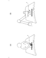
- FIG. 6 is a diagram showing an example of the principle of surface undulation detection by the strain sensor 1 for surface strain detection according to the present embodiment.
- the figure shows a case where the curvature of a cylindrical object 2 is measured by a strain sensor.
- the radius of the object 2 be r
- the thickness of the elastic sheet be t
- the nominal length of the strain gauge 20 be l.
- the strain of the strain gauge 20 can be defined as ⁇ l/l.
- the central angle of the arc formed by the strain gauge 20A along the object 2 is ⁇
- the relationship between the strain of the strain gauge 20 and the curvature of the object 2 can be evaluated by geometric calculation shown in Equation (1).
- the strain of the strain gauge 20 is proportional to the curvature of the object 2, and the proportionality constant is the thickness t of the flexible structure 10 to which the strain gauge 20 is attached (that is, the thickness t1 of the sheet 11 and the thickness t1 of the projection 12). height h1).
- the flexible structure portion 10 is provided with the projections 12, so that the thickness t1 of the sheet 11 is sufficiently reduced to ensure flexibility, and the height is increased by the projections 12.
- the projection 12 acts as a lever for the strain gauge 20 while giving flexibility to the sheet 11 .
- minute surface undulations of the object 2 can be amplified and detected.
- FIG. 7 is a diagram showing an example of the principle of surface undulation detection by a strain sensor 1A for surface strain detection according to a modification.
- the distance between the protrusions 12 in the plane direction (eg, the X-axis direction) of the flexible structure section 10 is 2d
- the height of the protrusions 12 is h
- the protrusions 12 are arranged in the plane direction (eg, the X-axis direction) of the flexible structure section 10.
- the strain of the strain gauge 20A is expressed by Equation (2) using the cosine equation and first-order Taylor approximation.
- ⁇ is the central angle of the arc formed by the strain gauge 20A along the object 2.
- formula (2) shows that the protrusion 12 with the height h has the function of amplifying the strain of the strain gauge 20A.
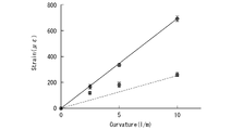
- FIG. 8 is a diagram showing an example of experimental results of a strain sensor for surface strain detection.
- the horizontal axis indicates the curvature of the object 2
- the vertical axis indicates the strain amount of the strain sensor. This example shows the amount of distortion when the curvature of the object 2 is 2.5, 5, and 10 (the unit is 1/m).
- the strain amount of the surface strain detecting strain sensor 1 (that is, the strain sensor without the fixing portion 22) is indicated by a dashed line
- the strain amount of the surface strain detecting strain sensor 1A that is, the strain sensor including the fixing portion 22) is indicated by a solid line. show.
- the strain sensor 1A for detecting surface strain with the fixing portion 22 has a strain amount 4.67 times that of the strain sensor 1 for detecting surface strain without the fixing portion 22. was done. That is, in the strain sensor 1 for detecting surface strain according to the present embodiment, the projecting portion 12 acts as a lever for the strain gauge 20, and the fixing portion 22 acts to further amplify the lever action. Surface undulations of the object 2 can be amplified and detected.
- the flexible structure portion 10 is provided with the projecting portion 12 .
- the strain gauge 20 has a plurality of contact portions 21 that are in contact with the apexes 13 of the plurality of protrusions 12, and is deformed following a change in the distance between the apexes 13 due to the deformation of the sheet 11, and responds to the deformation. It causes changes in electrical properties.
- the strain sensor 1 for detecting surface strain thus configured, the surface shape of the object 2 can be amplified and detected by the lever action of the protrusion 12 on the strain gauge 20 . Therefore, according to the strain sensor 1 for detecting surface strain, minute surface undulations can be detected with high sensitivity.
- the strain gauge 20 of the present embodiment at least some of the plurality of contact portions 21 are fixed to the top portion 13 .
- the strain gauge 20 is prevented from being displaced in the longitudinal direction (for example, the expansion and contraction direction of the strain gauge 20 or the direction of the X axis) at the top portion 13. . Therefore, according to the strain sensor 1 for detecting surface strain, the strain gauge 20 expands and contracts following changes in the surface undulation without deviation.
- the strain gauge 20 can more easily follow changes in surface undulations. According to the surface strain detecting strain sensor 1 configured in this way, minute surface undulations can be detected with high sensitivity.
- the strain gauge 20 of the modified example described above has a fixing portion 22 . Since the fixed portion 22 is fixed to the sheet 11 between the plurality of protrusions 12 adjacent to each other, the strain gauge 20 expands and contracts following changes in surface undulation without deviation. Further, according to the surface strain detecting strain sensor 1 configured in this manner, the lever action of the protrusion 12 on the strain gauge 20 can be further increased. Therefore, according to the strain sensor 1 for detecting surface strain, fine surface undulations can be detected with higher sensitivity.
- the projections 12 of the present embodiment are harder and the sheet 11 is softer.
- the thickness t1 of the sheet 11 is smaller than the height h1 of the protrusions 12 .
- the width of the protrusions 12 in the surface direction (X-axis direction or Y-axis direction) of the sheet 11 is configured to be smaller than the space p1 in the surface direction between the plurality of protrusions 12. be done. That is, when the portion of the flexible structure 10 having the projections 12 is defined as a peak and the portion without the projections 12 is defined as a valley, the ratio of the width of the valley to the width of the peak is greater. In other words, in the strain sensor 1 for detecting surface strain, the ratio of the width w of the projection 12 to the length of the flexible structure 10 in the longitudinal direction (for example, the X-axis direction) is small.
- the lever action of the protrusion 12 can be increased compared to the case where the ratio of the width w of the protrusion 12 is large. That is, according to the surface strain detecting strain sensor 1 configured in this manner, minute surface undulations can be detected with higher sensitivity.
- the sheet 11 has a longitudinal direction (X-axis direction) and a lateral direction (Y-axis direction).
- the protrusions 12 are arranged at least in the longitudinal direction (X-axis direction) at a predetermined interval p1.
- the strain gauge 20 deforms following the change in the interval p1 between the apexes 13 caused by the deformation of the sheet 11 in the longitudinal direction (X-axis direction).
- the strain gauge 20 can detect expansion and contraction in the longitudinal direction with higher sensitivity than in the lateral direction.
- the strain sensor 1 for detecting surface strain configured in this way, by utilizing the characteristic of the strain gauge 20 that it is possible to detect expansion and contraction in the longitudinal direction with higher sensitivity, minute surface undulations can be detected with higher sensitivity. can do.
- the sheet 11 and the protrusion 12 may be made of a material that is highly flexible, and may be integrally formed of the same material.
- the strain sensor 1 for detecting surface strain thus configured can be manufactured more easily and at a lower cost than when the sheet 11 and the protrusion 12 are made of different materials.
- SYMBOLS 1 Strain sensor for surface strain detection, 10... Flexible structure part, 11... Sheet, 12... Projection part, 13... Top part, 20... Strain gauge, 21... Contact part, 22... Fixed part
Landscapes
- Physics & Mathematics (AREA)
- General Physics & Mathematics (AREA)
- Measurement Of Length, Angles, Or The Like Using Electric Or Magnetic Means (AREA)
Priority Applications (1)
| Application Number | Priority Date | Filing Date | Title |
|---|---|---|---|
| JP2023517557A JPWO2022230879A1 (https=) | 2021-04-30 | 2022-04-26 |
Applications Claiming Priority (2)
| Application Number | Priority Date | Filing Date | Title |
|---|---|---|---|
| JP2021-077753 | 2021-04-30 | ||
| JP2021077753 | 2021-04-30 |
Publications (1)
| Publication Number | Publication Date |
|---|---|
| WO2022230879A1 true WO2022230879A1 (ja) | 2022-11-03 |
Family
ID=83848423
Family Applications (1)
| Application Number | Title | Priority Date | Filing Date |
|---|---|---|---|
| PCT/JP2022/018894 Ceased WO2022230879A1 (ja) | 2021-04-30 | 2022-04-26 | 面歪検出用ひずみセンサ |
Country Status (2)
| Country | Link |
|---|---|
| JP (1) | JPWO2022230879A1 (https=) |
| WO (1) | WO2022230879A1 (https=) |
Cited By (1)
| Publication number | Priority date | Publication date | Assignee | Title |
|---|---|---|---|---|
| CN119665798A (zh) * | 2024-11-22 | 2025-03-21 | 武汉真友科技有限公司 | 一种柔性应变传感器及其制备方法 |
Citations (6)
| Publication number | Priority date | Publication date | Assignee | Title |
|---|---|---|---|---|
| JPH05296709A (ja) * | 1992-04-16 | 1993-11-09 | Fanuc Ltd | 分布型触覚センサ |
| JPH07501640A (ja) * | 1991-11-26 | 1995-02-16 | エロ タッチシステムズ,インコーポレイテッド | 改良された絶縁スペーサ機構をもつコンタクト・タッチスクリーン |
| JP2002543409A (ja) * | 1999-04-29 | 2002-12-17 | ディッドジグローブ ピーティワイ リミテッド | 屈曲測定用電子式トランスジューサ |
| JP2004358634A (ja) * | 2003-06-06 | 2004-12-24 | Akito Sano | 触覚センサー内蔵ソフトフィンガー |
| JP2005195342A (ja) * | 2003-12-26 | 2005-07-21 | Akito Sano | 凹凸増幅部材および凹凸増幅部材を用いた凹凸検出方法 |
| JP2012248346A (ja) * | 2011-05-26 | 2012-12-13 | Japan Science & Technology Agency | 配線構造体、センサ、及び配線構造体の製造方法 |
-
2022
- 2022-04-26 WO PCT/JP2022/018894 patent/WO2022230879A1/ja not_active Ceased
- 2022-04-26 JP JP2023517557A patent/JPWO2022230879A1/ja active Pending
Patent Citations (6)
| Publication number | Priority date | Publication date | Assignee | Title |
|---|---|---|---|---|
| JPH07501640A (ja) * | 1991-11-26 | 1995-02-16 | エロ タッチシステムズ,インコーポレイテッド | 改良された絶縁スペーサ機構をもつコンタクト・タッチスクリーン |
| JPH05296709A (ja) * | 1992-04-16 | 1993-11-09 | Fanuc Ltd | 分布型触覚センサ |
| JP2002543409A (ja) * | 1999-04-29 | 2002-12-17 | ディッドジグローブ ピーティワイ リミテッド | 屈曲測定用電子式トランスジューサ |
| JP2004358634A (ja) * | 2003-06-06 | 2004-12-24 | Akito Sano | 触覚センサー内蔵ソフトフィンガー |
| JP2005195342A (ja) * | 2003-12-26 | 2005-07-21 | Akito Sano | 凹凸増幅部材および凹凸増幅部材を用いた凹凸検出方法 |
| JP2012248346A (ja) * | 2011-05-26 | 2012-12-13 | Japan Science & Technology Agency | 配線構造体、センサ、及び配線構造体の製造方法 |
Cited By (1)
| Publication number | Priority date | Publication date | Assignee | Title |
|---|---|---|---|---|
| CN119665798A (zh) * | 2024-11-22 | 2025-03-21 | 武汉真友科技有限公司 | 一种柔性应变传感器及其制备方法 |
Also Published As
| Publication number | Publication date |
|---|---|
| JPWO2022230879A1 (https=) | 2022-11-03 |
Similar Documents
| Publication | Publication Date | Title |
|---|---|---|
| KR101139010B1 (ko) | 박판의 프레스 성형 장치 및 프레스 성형 방법 | |
| KR102080426B1 (ko) | 4개 미만의 빔 표면 상에 계측기기를 갖는 힘/토크 센서 | |
| EP2093535B1 (en) | Coordinate measuring machine using mechanical scanning | |
| CN101171493B (zh) | 尺寸测量探针 | |
| JP7061784B2 (ja) | 触覚センサ、触覚測定装置、学習済みモデル、および識別装置 | |
| EP2154471B1 (en) | Measurement probe | |
| JP2008281403A (ja) | 剪断力検出装置及び物体把持システム | |
| JP6419156B2 (ja) | 触覚センサおよび手触り感の評価方法 | |
| WO2022230879A1 (ja) | 面歪検出用ひずみセンサ | |
| US12455204B2 (en) | Tactile sensor | |
| CN101871759A (zh) | 三坐标测量机 | |
| CN222231924U (zh) | 一种弱耦合柔性铰链六维力传感器 | |
| JP7072990B2 (ja) | 測定装置および測定方法 | |
| KR20180096913A (ko) | 3축 스트레인 센서 및 이의 제조방법 | |
| Metz et al. | New parallelogram 3D-displacement sensor for micro probing and dimensional metrology | |
| CN113043071B (zh) | 可感测低频力与高频力的力感测装置 | |
| Kurth et al. | Process Monitoring using Digital Twin-Based Sensors integrated in Tool Clamping Surfaces | |
| JPH079034A (ja) | 曲げ加工方法及びその装置 | |
| Kurokawa et al. | Scanning Tactile Sensor with Spiral Coil Structure Amplifying Detection Performance of Micro-concave | |
| Cheng et al. | On-line linear guideway monitoring using laser mouse sensor | |
| Maaß et al. | Deformation characteristics of thermoplastics in single point incremental forming | |
| CN119164279B (zh) | 一种可提高应变测量的灵敏度和精度的应变片装置 | |
| JP2007064786A (ja) | 力センサ | |
| KR20210087726A (ko) | 미세 로봇 관절용 센서장치 | |
| JP7747036B2 (ja) | 凹凸増幅用具 |
Legal Events
| Date | Code | Title | Description |
|---|---|---|---|
| 121 | Ep: the epo has been informed by wipo that ep was designated in this application |
Ref document number: 22795792 Country of ref document: EP Kind code of ref document: A1 |
|
| ENP | Entry into the national phase |
Ref document number: 2023517557 Country of ref document: JP Kind code of ref document: A |
|
| NENP | Non-entry into the national phase |
Ref country code: DE |
|
| 122 | Ep: pct application non-entry in european phase |
Ref document number: 22795792 Country of ref document: EP Kind code of ref document: A1 |