WO2022230367A1 - 盗難防止装置、盗難防止方法、およびプログラム - Google Patents
盗難防止装置、盗難防止方法、およびプログラム Download PDFInfo
- Publication number
- WO2022230367A1 WO2022230367A1 PCT/JP2022/009856 JP2022009856W WO2022230367A1 WO 2022230367 A1 WO2022230367 A1 WO 2022230367A1 JP 2022009856 W JP2022009856 W JP 2022009856W WO 2022230367 A1 WO2022230367 A1 WO 2022230367A1
- Authority
- WO
- WIPO (PCT)
- Prior art keywords
- theft device
- information
- event information
- user
- mode
- Prior art date
- Legal status (The legal status is an assumption and is not a legal conclusion. Google has not performed a legal analysis and makes no representation as to the accuracy of the status listed.)
- Ceased
Links
Images









Classifications
-
- G—PHYSICS
- G08—SIGNALLING
- G08B—SIGNALLING SYSTEMS, e.g. PERSONAL CALLING SYSTEMS; ORDER TELEGRAPHS; ALARM SYSTEMS
- G08B13/00—Burglar, theft or intruder alarms
- G08B13/18—Actuation by interference with heat, light, or radiation of shorter wavelength; Actuation by intruding sources of heat, light, or radiation of shorter wavelength
- G08B13/189—Actuation by interference with heat, light, or radiation of shorter wavelength; Actuation by intruding sources of heat, light, or radiation of shorter wavelength using passive radiation detection systems
- G08B13/194—Actuation by interference with heat, light, or radiation of shorter wavelength; Actuation by intruding sources of heat, light, or radiation of shorter wavelength using passive radiation detection systems using image scanning and comparing systems
- G08B13/196—Actuation by interference with heat, light, or radiation of shorter wavelength; Actuation by intruding sources of heat, light, or radiation of shorter wavelength using passive radiation detection systems using image scanning and comparing systems using television cameras
- G08B13/19678—User interface
-
- G—PHYSICS
- G06—COMPUTING OR CALCULATING; COUNTING
- G06V—IMAGE OR VIDEO RECOGNITION OR UNDERSTANDING
- G06V40/00—Recognition of biometric, human-related or animal-related patterns in image or video data
- G06V40/10—Human or animal bodies, e.g. vehicle occupants or pedestrians; Body parts, e.g. hands
- G06V40/107—Static hand or arm
- G06V40/113—Recognition of static hand signs
-
- G—PHYSICS
- G06—COMPUTING OR CALCULATING; COUNTING
- G06V—IMAGE OR VIDEO RECOGNITION OR UNDERSTANDING
- G06V40/00—Recognition of biometric, human-related or animal-related patterns in image or video data
- G06V40/20—Movements or behaviour, e.g. gesture recognition
- G06V40/28—Recognition of hand or arm movements, e.g. recognition of deaf sign language
-
- G—PHYSICS
- G08—SIGNALLING
- G08B—SIGNALLING SYSTEMS, e.g. PERSONAL CALLING SYSTEMS; ORDER TELEGRAPHS; ALARM SYSTEMS
- G08B13/00—Burglar, theft or intruder alarms
- G08B13/18—Actuation by interference with heat, light, or radiation of shorter wavelength; Actuation by intruding sources of heat, light, or radiation of shorter wavelength
- G08B13/189—Actuation by interference with heat, light, or radiation of shorter wavelength; Actuation by intruding sources of heat, light, or radiation of shorter wavelength using passive radiation detection systems
- G08B13/194—Actuation by interference with heat, light, or radiation of shorter wavelength; Actuation by intruding sources of heat, light, or radiation of shorter wavelength using passive radiation detection systems using image scanning and comparing systems
- G08B13/196—Actuation by interference with heat, light, or radiation of shorter wavelength; Actuation by intruding sources of heat, light, or radiation of shorter wavelength using passive radiation detection systems using image scanning and comparing systems using television cameras
- G08B13/19602—Image analysis to detect motion of the intruder, e.g. by frame subtraction
-
- G—PHYSICS
- G08—SIGNALLING
- G08B—SIGNALLING SYSTEMS, e.g. PERSONAL CALLING SYSTEMS; ORDER TELEGRAPHS; ALARM SYSTEMS
- G08B13/00—Burglar, theft or intruder alarms
- G08B13/18—Actuation by interference with heat, light, or radiation of shorter wavelength; Actuation by intruding sources of heat, light, or radiation of shorter wavelength
- G08B13/189—Actuation by interference with heat, light, or radiation of shorter wavelength; Actuation by intruding sources of heat, light, or radiation of shorter wavelength using passive radiation detection systems
- G08B13/194—Actuation by interference with heat, light, or radiation of shorter wavelength; Actuation by intruding sources of heat, light, or radiation of shorter wavelength using passive radiation detection systems using image scanning and comparing systems
- G08B13/196—Actuation by interference with heat, light, or radiation of shorter wavelength; Actuation by intruding sources of heat, light, or radiation of shorter wavelength using passive radiation detection systems using image scanning and comparing systems using television cameras
- G08B13/19617—Surveillance camera constructional details
- G08B13/19632—Camera support structures, e.g. attachment means, poles
-
- G—PHYSICS
- G08—SIGNALLING
- G08B—SIGNALLING SYSTEMS, e.g. PERSONAL CALLING SYSTEMS; ORDER TELEGRAPHS; ALARM SYSTEMS
- G08B25/00—Alarm systems in which the location of the alarm condition is signalled to a central station, e.g. fire or police telegraphic systems
- G08B25/001—Alarm cancelling procedures or alarm forwarding decisions, e.g. based on absence of alarm confirmation
Definitions
- the present disclosure relates to an anti-theft device, an anti-theft method, and a program.
- a space public space
- users generally carry their belongings with them in order to prevent their belongings such as valuables from being stolen.
- a user who is working on a laptop closes and carries the laptop in the middle of the work, and after returning to his or her seat, opens the laptop again and starts working.
- Patent Document 1 describes a technique aimed at detecting a suspicious object appearing in time-series images.
- Patent Document 1 it is possible to detect unusual behavior.
- a third party taking away the user's belongings falls under the act of theft, but it is a legitimate act for the user to take away the user's personal belongings. Therefore, if the action of taking away an article is defined as normal action, the removal of the user's article by a third party will be ignored as normal action.
- an action of taking away an item is defined as an action different from normal, even the action of the user taking away his or her belongings will be detected as an action different from normal.
- Patent Document 1 creates and transmits individual identification information when a suspicious entity is detected, even if such handling is performed, it cannot be expected to have the effect of deterring suspicious entities from acting differently from normal.
- the purpose of this disclosure is mainly to prevent theft of the user's belongings in public spaces.
- an anti-theft device includes: means for acquiring first event information regarding an alert mode; means for controlling the alert mode according to the first event information; (2) means for monitoring movement of the object; and means for outputting an alarm when the alert mode is active and the movement of the object is detected.
- FIG. 1 is a block diagram showing the configuration of an anti-theft system of this embodiment
- FIG. 1 is a block diagram illustrating the configuration of an anti-theft device of this embodiment
- FIG. 3 is a block diagram illustrating the configuration of an output device connected to the anti-theft device of this embodiment
- FIG. 10 is a block diagram which illustrates the structure of the protected object of this embodiment. It is a figure which shows the application example of the anti-theft device of this embodiment.
- FIG. 10 illustrates an example set of gestures for enabling/disabling alert mode; It is a figure which shows the behavior example of an indicator when caution mode is effective.
- FIG. 10 is a diagram showing an example of the behavior of the alarm device when the alert mode is valid and the movement of the object to be protected is detected;
- FIG. 10 is a diagram showing an example of the behavior of the alarm device when the alert mode is valid and the movement of the object to be protected is detected;
- FIG. 10 is a diagram showing an example of the behavior of the alarm device when the alert mode is disabled and the movement of the object to be protected is detected; It is a figure which shows the data structure of the user database of this embodiment. It is a figure which shows the data structure of the protection object database of this embodiment.
- 4 is a flowchart of power supply start processing according to the embodiment; It is a flow chart of standby processing of this embodiment.
- FIG. 4 is an explanatory diagram of a hand detection area and an entry prohibition area according to the embodiment; 4 is a flowchart of anti-theft processing according to the embodiment; 5 is a flowchart of power supply control processing according to the embodiment;
- FIG. 1 is a block diagram showing the configuration of the anti-theft system of this embodiment.
- the anti-theft system 1 includes an anti-theft device 10 and an object 30 to be protected.
- the anti-theft device 10 provides the protected object 30 with the wireless power supply service in addition to the anti-theft service. Therefore, the anti-theft device 10 can also be called a power transmission device.
- the protected object 30 can also be called a power receiving device.
- the anti-theft device 10 and the object to be protected 30 may be configured to communicate wirelessly with each other.
- the method of wireless communication is arbitrary, but for example, Bluetooth (registered trademark), ZigBee (registered trademark), specified low-power wireless communication, or wireless LAN (Local Area Network).
- the anti-theft device 10 provides an anti-theft service for the protected object 30 in accordance with instructions from the user of the protected object 30 (the owner of the protected object 30).
- the anti-theft device 10 is installed in a public space.
- a public space is, for example, a restaurant (for example, a cafe, a restaurant), or a space where a person other than the user of the protected object 30 can stay (that is, a robbery damage can occur) such as a coworking space.
- the anti-theft device 10 wirelessly supplies power to the protection target 30 in response to an instruction from the user of the protection target 30 or a power supply request from the protection target 30 or another communication device operated by the user. I do.
- the protected object 30 includes a battery (not shown).
- the protected object 30 uses the energy of the power transmission beam emitted from the anti-theft device 10 to charge the battery.
- the protected object 30 is any electronic device that can be powered by a battery.
- the protected object 30 is a mobile computer (eg, smart phone, tablet terminal, laptop computer, wearable device) or other electronic device, or a mobile battery.
- the number of the anti-theft device 10 and the number of the objects to be protected 30 are one, but the number of the anti-theft device 10 and the number of the objects to be protected 30 are not limited to one.
- information identifying the protected objects 30 or information identifying the user of the protected objects 30 may be included in the user's instruction or power supply request.
- the anti-theft device 10 can identify the protected object 30 (target power receiving device) to which wireless power is to be supplied.
- a plurality of anti-theft devices 10 may work together to supply power wirelessly, or one of them may supply power wirelessly.
- the anti-theft device 10 that performs wireless power supply may be specified by the target power receiving device, or may be determined by one or more anti-theft devices 10 that have received a user's instruction or power supply request.
- FIG. 2 is a block diagram illustrating the configuration of the anti-theft device of this embodiment.
- FIG. 3 is a block diagram illustrating the configuration of an output device connected to the anti-theft device of this embodiment.
- the anti-theft device 10 includes a storage device 11, a processor 12, an input/output interface 13, a communication interface 14, and a power transmission section 15.
- Anti-theft device 10 is connectable with at least one of input device 16 and output device 17 .
- the storage device 11 is configured to store programs and data.
- the storage device 11 is, for example, a combination of ROM (Read Only Memory), RAM (Random Access Memory), and storage (eg, flash memory or hard disk).
- Programs include, for example, the following programs.
- ⁇ OS (Operating System) program ⁇ Application program for executing information processing (for example, anti-theft processing, power supply control processing)
- the data includes, for example, the following data. ⁇ Databases referenced in information processing ⁇ Data obtained by executing information processing (that is, execution results of information processing)
- Processor 12 realizes the functions of anti-theft device 10 (in particular, the function of preventing theft of protected object 30 and the function of controlling power transmission unit 15) by activating a program stored in storage device 11.
- configured as Processor 12 is an example of a computer or controller.
- the input/output interface 13 acquires a signal (e.g., a user's instruction, sensing data, or a combination thereof) from an input device 16 connected to the anti-theft device 10, and an output device connected to the anti-theft device 10. 17 (eg, a control signal, an image signal, or a combination thereof).
- a signal e.g., a user's instruction, sensing data, or a combination thereof
- 17 e.g., a control signal, an image signal, or a combination thereof.
- the input device 16 is, for example, a keyboard, pointing device, touch screen, sensor (eg, optical sensor), or a combination thereof.
- Optical sensors can include, for example, at least one of the following: ⁇ Camera ⁇ Lidar ⁇ ToF (Time Of Flight) camera
- An optical sensor photographs the surroundings of the object to be protected 30 in response to a control signal from the processor 12, for example.
- the camera may be configured to be able to control at least one of the position and orientation of the camera according to the position of the object 30 to be protected.
- the position and orientation of the camera are preferably controlled so that the user of the protected object 30 and other human faces are not included in the photographing range.
- the output device 17 is, for example, a display, speaker, light source, alarm device, indicator, or a combination thereof.
- the output device 17 includes a light source 171, an alarm device 172, and an indicator 173.
- the light source 171 illuminates the surroundings of the protection object 30 according to control from the processor 12, for example. This makes it possible to more accurately identify an edge, which will be described later, from an image (data) captured by a camera.
- the light source 171 emits light along the shooting direction of the camera.
- an object to be monitored e.g., a human hand
- part of the irradiation light is reflected by the object to be monitored. not reach. That is, there is a difference in the amount of light that reaches the monitored object and the area blocked by the monitored object. Therefore, in the image captured by the camera, the luminance of the monitored object is high, while the luminance of the surroundings of the monitored object is relatively low (a shadow is formed). Therefore, according to the light source 171, the edge of the monitored object can be specified more accurately by increasing the luminance difference between the monitored object and its surroundings.
- the light source 171 may be configured such that at least one of the position and orientation of the light source 171 can be controlled according to the position of the object 30 to be protected.
- the light source 171 may be lit continuously, or may be lit intermittently according to the shooting of the camera.
- Alarm device 172 outputs an alarm in accordance with control from anti-theft device 10 .
- the alarm device 172 may be arranged so that people around the protected object 30 (people who have taken away the protected object 30, or users or administrators of public spaces) can more easily perceive the alarm. It is installed around the object 30 .
- Alarms are not limited to human vision or hearing, but stimulate the senses of touch, smell, or taste to make surrounding humans perceive the presence of the alarm itself and/or the content of the alarm.
- the alarm device 172 is, for example, a light source, a lamp, a display, a projector, a smoke generator, a speaker, a vibration device, a mist generator, an odor generator, a taste stimulator (for example, a taste stimulus that can be supplied to the wearer's tongue). mouthpiece devices), or combinations thereof.
- alarm device 172 may be a communication device carried by the user of protected object 30 .
- the communication device carried by the user of the protected object 30 may be registered in advance in association with the user or the protected object 30, or may be detected based on the location information of the communication device.
- the anti-theft device 10 can notify the user of the protected object 30 early that the protected object 30 has been taken away by causing the communication device to output an alarm.
- the indicator 173 outputs visual information under the control of the anti-theft device 10.
- the anti-theft device 10 generates a visual information output instruction according to its own operation mode (for example, enable/disable an alert mode, enable/disable a power feeding mode, or a combination of these) and transmit it to the indicator 173. do.
- the indicator 173 emits light in a first color when the security mode of the anti-theft device 10 is enabled and in a second color different from the first color when the security mode of the anti-theft device 10 is disabled. Glow in color.
- the indicator 173 may be a device independent of the light source 171 or the warning device 172, or at least one of the light source 171 or the warning device 172 may also serve as the indicator 173.
- Communication interface 14 is configured to control communication between anti-theft device 10 and an external device (eg, protected object 30 or other user-operated communication device).
- the communication interface 14 is a wireless communication module that supports at least one of Bluetooth, ZigBee, specified low-power wireless communication, or wireless LAN.
- the power transmission unit 15 is configured to radiate an electromagnetic wave for power supply as a power transmission beam (that is, perform wireless power supply) according to a control signal from the processor 12 .
- the feeding electromagnetic wave is, for example, microwave, millimeter wave, or light wave (laser light or LED light). In the following description, it is assumed that the feeding electromagnetic waves are microwaves.
- the power transmission unit 15 includes a signal source, a signal processing circuit, and multiple antennas (an example of a “beam radiation element”).
- the signal source is, for example, an oscillator that generates electromagnetic waves for feeding.
- the signal processing circuit performs signal processing including, for example, at least one of phase adjustment, amplitude adjustment, and filtering, on the feeding electromagnetic wave generated by the signal source.
- the signal processing circuitry may comprise amplifiers for amplitude adjustment (power amplification).
- the antenna radiates the feeding electromagnetic wave output from the signal processing circuit into space as a power transmission beam.
- a lamp as a warning device 172 or indicator 173 may be mounted around the antenna. As an example, by turning on a lamp, it is possible to make surrounding people perceive that wireless power supply is being performed.
- the power transmission unit 15 may have a planar antenna or a linear antenna.
- the multiple antennas can be arranged in arrays, matrices, or in different manners.
- a plurality of antennas form a power transmission plane.
- the power transmission surface corresponds to a portion of the power transmission section 15 that is in charge of emitting the power transmission beam.
- the power transmission aspect depends on the configuration of the power transmission unit 15 (eg, the size, shape, placement, and number of antennas). As an example, a rectangular power transmission surface that includes all the antennas included in power transmission section 15 may be defined.
- FIG. 4 is a block diagram illustrating the configuration of the object to be protected according to this embodiment.
- the protection target 30 includes a storage device 31, a processor 32, an input/output interface 33, a communication interface 34, and a power receiving section 35.
- the protected object 30 is connectable with at least one of an input device 36 and an output device 37 .
- the storage device 31 is configured to store programs and data.
- Storage device 31 is, for example, a combination of ROM, RAM, and storage (eg, flash memory or hard disk).
- Programs include, for example, the following programs. ⁇ OS program ⁇ Application program that executes information processing
- the data includes, for example, the following data. ⁇ Databases referenced in information processing ⁇ Execution results of information processing
- the processor 32 is configured to implement the functions of the protected object 30 by activating the program stored in the storage device 31 .
- Processor 32 is an example of a computer.
- the input/output interface 33 is configured to acquire signals (eg, user instructions, sensing data, or a combination thereof) from an input device 36 connected to the protected object 30 .
- the input/output interface 33 is also configured to output a signal (eg, a control signal, an image signal, or a combination thereof) to an output device 37 connected to the protected object 30 .
- the input device 36 is, for example, a keyboard, pointing device, touch screen, sensor (eg, attitude sensor), or a combination thereof.
- the attitude sensor can include, for example, at least one of the following. ⁇ Acceleration sensor ⁇ Angular velocity sensor ⁇ Magnetic sensor
- the output device 37 is, for example, a display.
- Communication interface 34 is configured to control communication between protected object 30 and an external device (eg, anti-theft device 10). As an example, the communication interface 34 transmits sensing data to an external device.
- the communication interface 34 is, for example, a wireless communication module that supports at least one of Bluetooth, ZigBee, specific low-power wireless communication, or wireless LAN.
- the power reception unit 35 is configured to receive the power transmission beam emitted into space by the power transmission unit 15 and obtain power.
- power receiving unit 35 includes an antenna and a power converter.
- the antenna receives an electromagnetic wave for feeding (power transmission beam) propagating in space.
- the power converter converts the feeding electromagnetic waves received by the antenna into (DC) power. If the feeding electromagnetic wave is a microwave, the antenna and power converter may be rectennas. When the feeding electromagnetic wave is a light wave, the antenna and power converter may be photoelectric converters.
- the power receiving unit 35 may include a planar antenna or a linear antenna.
- the multiple antennas can be arranged in arrays, matrices, or in different manners.
- a plurality of antennas form a power receiving surface (which can also be referred to as an aperture surface).
- the power receiving surface corresponds to a portion of the power receiving unit 35 that receives the power transmission beam.
- the power receiving surface depends on the configuration of power receiving unit 35 (for example, the size, shape, arrangement, and number of antennas). As an example, a rectangular power receiving surface that includes all the antennas included in power receiving unit 35 may be defined.
- the power receiving surface may be an effective aperture based on the radio wave characteristics of the power receiving unit 35 .
- the protected object 30 includes a battery (not shown).
- the battery supplies power to each part of the object to be protected 30 .
- the battery can be charged with power obtained by the power receiving unit 35 .
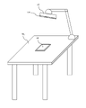
- FIG. 5 is a diagram showing an application example of the anti-theft device of this embodiment.
- FIG. 6 is a diagram illustrating an example set of gestures for enabling/disabling alert mode.
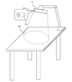
- FIG. 7 is a diagram showing an example behavior of the indicator when the alert mode is enabled.
- FIG. 8 is a diagram showing an example of the behavior of the alarm device when the alert mode is valid and the movement of the object to be protected is detected.
- FIG. 9 is a diagram showing an example of the behavior of the alarm device when the alert mode is disabled and the movement of the object to be protected is detected.
- the anti-theft device 10 is mounted on a table TBL installed in restaurants, libraries, co-working spaces, and the like.
- a protected object 30 is also placed on the table TBL.
- the anti-theft device 10 and camera are positioned and oriented so as to look down on the protected object 30 .
- the anti-theft device 10 is supported by arms, but the anti-theft device 10 may be installed in a manner different from that in FIG.
- the anti-theft device 10 may be attached to structures such as ceilings, walls, pillars, windows, and the like.
- the anti-theft device 10 operates according to a combination of valid/invalid of the security mode and valid/invalid of the power supply mode.
- the anti-theft device 10 has an inactive alert mode, but an arbitrary state (that is, enabled or disabled) in the power supply mode.
- the anti-theft device 10 extinguishes the indicator 173 while the security mode is disabled. This allows the user of the object 30 to be protected to recognize that the security mode of the anti-theft device 10 is disabled.
- the user of the protected object 30 can instruct activation/deactivation of the security mode of the anti-theft device 10 .
- a user may indicate activation/deactivation of the security mode of anti-theft device 10 using a gesture set including one or more specific gestures.
- the gesture set GS is, for example, a permutation of hand gestures.
- the gestures that make up the gesture set are not limited to hand gestures.
- a gesture set may also be a combination of multiple gestures (in no particular order). However, from a security enhancement point of view, the gesture set is preferably permutations of as many gestures as possible.
- the user of the protected object 30 can instruct the anti-theft device 10 to activate the security mode of the anti-theft device 10 when temporarily leaving the table TBL.
- the anti-theft device 10 causes the indicator 173 to emit light as shown in FIG. 7, for example. Thereby, the user of the protected object 30 can recognize that the security mode of the anti-theft device 10 has been activated.
- the anti-theft device 10 monitors removal of the protected object 30 while the user is away. As shown in FIG. 8, when the anti-theft device 10 detects that the protected object 30 has been taken away, the anti-theft device 10 causes the alarm device 172 to output an alarm (for example, output sound from a speaker). Therefore, the user can leave the table TBL with peace of mind while leaving the object 30 to be protected on the table TBL. In other words, there is no need to remove the protection object 30 from the table TBL, carry the protection object 30, and prepare the protection object 30 again on the table TBL. Further, when the protected object 30 is provided with the wireless power supply service (that is, the power supply mode of the anti-theft device 10 is valid), the wireless power supply can be continued even while the user is absent. The battery of the object 30 can be charged early.
- the wireless power supply service that is, the power supply mode of the anti-theft device 10 is valid
- the user of the protected object 30 instructs the anti-theft device 10 to disable the security mode of the anti-theft device 10 when returning to the table TBL.
- the anti-theft device 10 extinguishes the indicator 173 as shown in FIG. 5, for example.
- the user of the protected object 30 can recognize that the security mode of the anti-theft device 10 has been disabled.
- the anti-theft device 10 does not activate the alarm device 172 when the alert mode is disabled, regardless of the state of the protected object 30, unlike the example of FIG. Thereby, the user can remove the protection object 30 from the table TBL without activating the alarm device 172 .
- FIG. 10 is a diagram showing the data structure of the user database of this embodiment.
- User information is stored in the user database.
- User information is information about the user of the protection target 30 .
- the user database includes an "ID” field, a "name” field, a “hand information” field, a “contact” field, and a "power supply amount within the period” field.
- the user ID information is stored in the "ID" field.
- the user ID information is information that identifies the user of the protected object 30 .
- User name information is stored in the "Name" field.
- the user name information is information related to the user name of the protected object 30 .
- the user name may be the user's nickname or the user's real name.
- the "hand information" field stores hand information of the user of the object to be protected 30.
- the hand information is information about a human (user's) hand.
- Hand information can include, for example, at least one of the following: Information about one or more gestures represented by a human hand (hand gestures) Information about the biometric features of a human hand (e.g., skeleton, wrinkles, palmistry, veins, or a combination thereof)
- the hand information of the user of the protected object 30 can be registered, for example, when the wireless power supply service or the anti-theft service is used for the first time.
- the gestures may be specified by the user or determined by the anti-theft device 10 or its higher system.
- the anti-theft device 10 notifies the user of the gesture when at least a part of one or more gestures designated by the user corresponds to a gesture that can be easily guessed by a third party or a gesture that the user unconsciously uses. may be performed. This prompts the user to change the registered gesture, thereby preventing disabling of the alert mode by a third party or enabling/disabling of the alert mode unintentionally by the user.
- the anti-theft device 10 may refuse registration of such gestures.
- Two or more of the hand information serving as a trigger for disabling the guard mode, the hand information serving as a trigger for enabling the guard mode, and the hand information serving as a trigger for enabling the power supply mode may be the same. This reduces the amount of hand information that the user of the protected object 30 needs to store.
- hand information serving as a trigger for activating the power supply mode may be reused as hand information serving as a trigger for disabling the guard mode or as hand information serving as a trigger for activating the guard mode.
- the user of the protected object 30 adds the hand information for controlling the security mode of the anti-theft device 10 only by registering the hand information for activating the power supply mode when starting to use the wireless power supply service. It is possible to register without work.
- the authentication information can include at least one of the following. information about one or more gestures represented by parts other than a human hand biometric information about parts other than a human hand a passcode (e.g., at least one permutation of letters, numbers, or symbols) ("code information ” example) ⁇ An imaged code (for example, a two-dimensional barcode) (an example of “code information”)
- the contact information is stored in the "contact" field.
- the contact information is information regarding the contact information of the user of the protected object 30 .
- Contact information includes, for example, at least one of the following: ⁇ E-mail address ⁇ SNS (Social Networking Service) account information ⁇ Phone number
- the intra-period power supply amount information is information related to the amount of power supplied by the user of the protected object 30 by using the wireless power supply service within a predetermined total period (for example, one month).
- the power supply amount information within the period can be used to calculate the amount charged to the user by the wireless power supply service provider.
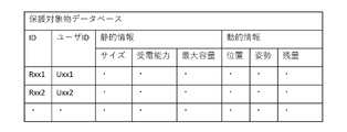
- FIG. 11 is a diagram showing the data structure of the protected object database of this embodiment.
- Protection object information is stored in the protection object database.
- the protected object information is information about the protected object 30 .
- the protected object database includes an "ID” field, a "user ID” field, a “static information” field, and a “dynamic information” field. Each field is associated with each other.
- a user ID is stored in the "user ID" field.
- a user ID is a foreign key that uniquely identifies the associated record in the user database (FIG. 10).
- the "static information” field stores static information about the protection object 30.
- the static information of the protected object 30 is information that is assumed to have no possibility of changing from the start to the end of the provision of the wireless power supply service among the attributes or states of the protected object 30 .
- the static information is the size of the power receiving surface, the shape of the power receiving surface, the power receiving capability of the power receiving unit 35, and the maximum capacity of the battery.
- the size of the power receiving surface represents the actual size of the power receiving surface.
- the size of the receiving surface can include at least one of the following. ⁇ The length of part or all of the outline defining the power receiving surface (for example, the length of the side of the power receiving surface, or the total length of the power receiving surface) ⁇ The length between two points on the contour defining the power receiving surface (for example, the length of the diagonal line of the power receiving surface, the radius of the power receiving surface, the length of the major axis of the power receiving surface, or the length of the minor axis of the power receiving surface) ⁇ The area surrounded by the outline defining the power receiving surface
- the power receiving capability of the power receiving unit 35 includes, for example, at least one of the following. - Size of the power receiving surface - Shape of the power receiving surface - Power range that the power receiving unit 35 can receive - Frequency that the power receiving unit 35 can receive - Type of polarization that the power receiving unit 35 can receive
- the power receiving capability of the power receiving unit 35 may be categorized as a power receiving class.
- the shape of the power receiving surface represents the geometry of the power receiving surface.
- the shape of the power receiving surface is, for example, any combination of curves (eg, circle or ellipse), any combination of straight lines (eg, polygon), or any combination of curves and straight lines (eg, sector).
- the "dynamic information” field stores the dynamic information of the protection object 30.
- the dynamic information of the protection target 30 is information that is assumed to have a possibility of changing from the start to the end of the provision of wireless power supply among the attributes or states of the protection target 30 .
- the dynamic information is the position of the power receiving surface, the orientation of the power receiving surface, and the remaining battery power. If the protected object 30 moves or rotates between the start and end of wireless power supply, at least one of the position of the power receiving surface and the posture of the power receiving surface changes. From the start to the end of wireless power supply, the remaining amount of the battery of the object to be protected 30 continues to increase.
- the position of the power receiving surface represents the relative position of the power receiving surface with respect to the power transmitting surface.
- the position of the power receiving surface can include at least one of the following. ⁇ Coordinates of one or more reference points (for example, vertices) on the contour defining the power receiving surface ⁇ Coordinates of one or more reference points (for example, at least one of the center point and the center of gravity) inside the power receiving surface
- the attitude of the power receiving surface represents the orientation of the power receiving surface relative to the reference plane (eg, horizontal plane or power transmission plane).
- the attitude of the power receiving surface is the inclination of the power receiving surface with respect to the reference plane (for example, at least one of the roll angle, pitch angle, and yaw angle of the power receiving surface).
- FIG. 12 is a flowchart of power supply start processing according to the present embodiment.
- the power feeding start process in FIG. 12 is started when any one of the following start conditions is satisfied.
- the anti-theft device 10 receives a power supply request from the object to be protected 30 -
- the anti-theft device 10 receives a communication device other than the object to be protected 30 (for example, another communication device operated by the user of the object to be protected 30) Received a power supply request from the specified date and time
- the anti-theft device 10 identifies a user (S101). Specifically, the processor 12 identifies the user of the protected object 30 (that is, the target power receiving device) to which wireless power is to be supplied. In a first example, the processor 12 refers to the user ID included in the power supply request received from the protected object 30 or other communication device, and identifies the user identified by the user ID. In a second example, the processor 12 refers to the protected object ID included in the power supply request received from the protected object 30 or other communication device, and the protected object ID in the protected object database (FIG. 11). Identify the user identified by the associated user ID. In a third example, the processor 12 identifies the user associated with the start date and time of the power supply start process in FIG. 12 (that is, the user who has reserved the use of the wireless power supply service).
- the anti-theft device 10 acquires hand information (S102). Specifically, the processor 12 acquires hand information (an example of “second event information regarding power supply mode”) used for user authentication for starting wireless power supply to the protection object 30 .
- processor 12 acquires an image of the user from a camera via input/output interface 13 .
- processor 12 may optionally control at least one of the position or orientation of the camera. If the hand information is a gesture set of hand gestures, processor 12 obtains an image of the user's hand.
- Processor 12 extracts hand information by analyzing the image.
- processor 12 obtains an image of the user from protected object 30 or other communication device via communication interface 14 .
- Processor 12 extracts hand information by analyzing the image.
- processor 12 obtains hand information transmitted from protected object 30 or other communication device via communication interface 14 .
- the anti-theft device 10 performs user authentication (S103). Specifically, the processor 12 determines whether or not the hand information acquired in step S102 matches the user's hand information (hereinafter referred to as "correct hand information") specified in step S101. As an example, processor 12 identifies correct move information by referring to the user database (FIG. 11).
- Control parameters determine the radial direction and beam shape of the transmitted beam.
- the control parameters may be generated dependent on at least one of static or dynamic information about the receiving surface.
- the processor 12 sets control parameters so that the power transmission beam emitted from the power transmission unit 15 is focused on a spot that matches the size of the power receiving surface, the shape of the power receiving surface, and the orientation of the power receiving surface at the position of the power receiving surface. Generate.
- the processor 12 generates control parameters such that the intensity of the transmitting beam is half the maximum value (half the value) at at least some of the edges (ie sides or vertices) of the receiving surface.
- the processor 12 generates control parameters such that the intensity of the transmit beam is null (that is, has a zero value) at least part of the edge of the receive surface.
- step S103 the anti-theft device 10 terminates the power feeding start process of FIG. In this case, the power feeding mode of the anti-theft device 10 is not activated.
- the anti-theft device 10 may acquire hand information (S102) again.
- FIG. 13 is a flowchart of standby processing according to the present embodiment.
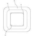
- 14A and 14B are explanatory diagrams of the hand detection area and the no-entry area according to the present embodiment.
- the standby process in FIG. 13 is started when any one of the following start conditions is met. -
- the power feeding mode of the anti-theft device 10 is activated (that is, step S104 in Fig. 12 is executed) -
- the alert mode of the anti-theft device 10 is disabled (that is, step S125 is executed).
- the anti-theft device 10 has recognized the object to be protected 30 from, for example, an image taken by a camera - A predetermined date and time has arrived
- the anti-theft device 10 monitors the hand detection area (S110). Specifically, the processor 12 transmits an image (that is, an image captured so as to include the hand detection area) representing the state of the hand detection area (an example of the “predetermined area”) from the camera via the input/output interface 13. get.
- the processor 12 may optionally control at least one of the position and orientation of the camera so that the hand detection area is captured.
- the processor 12 obtains edge information by performing edge analysis on the acquired image.
- the processor 12 refers to the edge information and monitors the edges of a moving body (living body (especially human hand) or object).
- the hand detection area is an area for the anti-theft device 10 to detect the user's hand.
- a hand detection area is defined around the protected object 30 .
- the anti-theft device 10 may, for example, turn on the light source 171 and allow the user to recognize the range illuminated by the light source 171 as the hand detection area.
- the power transmission beam emitted by the power transmission unit 15 of the anti-theft device 10 is received in the power receiving range RR of the power receiving surface RS of the object to be protected 30 .
- the path of the power transmission beam PTB (for example, around the power receivable range RR), there occurs a region where a large amount of power is irradiated for a living body or object.
- a region in which the power received by the human body from the power transmission beam may be equal to or greater than a threshold is defined as a no-entry region RA.
- the threshold is determined, for example, with reference to radio wave protection guidelines.
- a hand detection area HA is defined around the entry prohibition area RA.
- the no-entry area RA is defined closer to the object to be protected 30 than the hand detection area HA.
- the anti-theft device 10 can acquire the user's hand information in the hand detection area HA in front of the prohibited area RA.
- the hand detection area HA can be defined based on at least one of the following. ⁇ Received power ⁇ Distance from prohibited area RA ⁇ Camera shooting range
- the anti-theft device 10 finds an edge of a stationary object in the hand detection area HA, it can ignore the edge.
- the anti-theft device 10 registers the position information of the edge of a stationary object existing within the hand detection area HA as a white list before starting wireless power supply, so that the hand detected within the hand detection area HA during wireless power supply can be detected. It can be determined whether an edge can be ignored.
- the anti-theft device 10 may recognize moving or stationary objects from images through image recognition processing. This makes it possible to determine whether the edge found in the hand detection area HA is the edge of the moving object.
- Edge information is information about edges in an image.
- An edge is a point of change in brightness of an image (for example, a point at which the first order derivative of the spatial function of brightness reaches a maximum or a minimum, or a point at which the second order derivative of the spatial function of brightness crosses zero).
- the processor 12 illuminates the light source 171 so as to illuminate at least the hand detection area when the camera captures an image, thereby increasing the luminance difference between the monitored object (for example, a human hand) and its surroundings, thereby making the edge of the monitored object more visible. can be precisely identified.
- the light source 171 illuminates the hand detection area so that the inside and outside of the hand detection area can be distinguished (for example, by the amount of light or the color of the light), so that the location where the user of the protected object 30 should reach out his/her hand (that is, , hand detection area).
- the anti-theft device 10 repeatedly monitors the hand detection area (S110) until an edge is detected or the standby process of FIG. 13 ends.
- the anti-theft device 10 acquires hand information (S111).
- the processor 12 refers to the image acquired in step S110, and acquires hand information (an example of "first event information regarding alert mode").
- processor 12 generates hand information by analyzing the image.
- the anti-theft device 10 performs user authentication (S112). Specifically, the processor 12 authenticates the user of the protection object 30 by determining whether the hand information acquired in step S111 matches the correct hand information. As an example, the processor 12 identifies correct move information corresponding to the user of the protected object 30 by referring to the user database ( FIG. 11 ).
- step S113 the anti-theft device 10 activates the security mode (S113). Specifically, processor 12 activates the security mode of anti-theft device 10 . Additionally, processor 12 may change the visual information that causes indicator 173 to output. With the end of step S113, the anti-theft device 10 ends the standby process of FIG.
- step S112 the anti-theft device 10 monitors the hand detection area (S110).
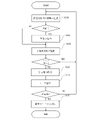
- FIG. 15 is a flowchart of anti-theft processing according to this embodiment.
- the anti-theft processing in FIG. 15 is started when any of the following start conditions are satisfied. - In the standby process of FIG. 13, the security mode of the anti-theft device 10 is activated (that is, step S113 is executed). - The anti-theft device 10 has recognized the object to be protected 30 from, for example, an image taken by a camera - A predetermined date and time has arrived
- the anti-theft device 10 monitors movement of the protected object (S120). Specifically, the processor 12 acquires images from the camera via the input/output interface 13 . Here, processor 12 may optionally control at least one of the position or orientation of the camera. The processor 12 analyzes the acquired image to determine whether the protection object 30 has moved. As an example, processor 12 may determine that protected object 30 has moved when at least one of the following conditions is met. ⁇ The protected object 30 is not shown in the image. ⁇ The position of the protected object 30 has changed compared to the image acquired in the past. ⁇ The protected object 30 is outside the predetermined area.
- the anti-theft device 10 may determine that the protection target 30 has moved when the connection with the protection target 30 is cut.
- the anti-theft device 10 outputs an alarm (S121).
- the processor 12 causes the alarm device 172 to output an alarm to stimulate the senses of, for example, people around the alarm device 172 or the user of the protected object 30 .
- processor 12 can do at least one of the following.
- the speaker as the warning device 172 is made to output a sound warning (for example, warning voice or warning sound).
- the light source or lamp as the alarm device 172 is caused to output an alarm by light.
- the display as the alarm device 172 is made to output an alarm screen.
- the vibration device as the warning device 172 is made to output a warning by vibration.
- the anti-theft device 10 monitors the hand detection area (S122). Specifically, the processor 12 acquires an image representing the state of the hand detection area from the camera via the input/output interface 13 . Here, the processor 12 may optionally control at least one of the position and orientation of the camera so that the hand detection area is captured. The processor 12 obtains edge information by performing edge analysis on the acquired image. The processor 12 refers to the edge information and monitors the edges of the living body or object.
- the processor 12 illuminates the light source 171 so as to illuminate at least the hand detection area when the camera captures an image, thereby increasing the luminance difference between the monitored object (for example, a human hand) and its surroundings, thereby making the edge of the monitored object more visible. can be precisely identified.
- the light source 171 illuminates the hand detection area so that the inside and outside of the hand detection area can be distinguished (for example, by the amount of light or the color of the light), so that the location where the user of the protected object 30 should reach out his/her hand (that is, , hand detection area).
- the anti-theft device 10 acquires hand information (S123).
- the processor 12 refers to the image acquired in step S122, and acquires hand information (an example of "first event information regarding alert mode").
- processor 12 generates hand information by analyzing the image.
- the anti-theft device 10 performs user authentication (S124). Specifically, the processor 12 authenticates the user of the protection object 30 by determining whether or not the hand information acquired in step S123 matches the correct hand information. As an example, the processor 12 identifies correct move information corresponding to the user of the protected object 30 by referring to the user database ( FIG. 11 ).
- the anti-theft device 10 disables the security mode (S125). Specifically, processor 12 disables the security mode of anti-theft device 10 . Additionally, processor 12 may change the visual information that causes indicator 173 to output. Here, if the warning device 172 is outputting a warning when it is determined to disable the warning mode, the processor 12 stops outputting the warning. As a result, even if the user of the object to be protected 30 erroneously activates the alarm device 172, the output of the alarm can be quickly stopped. With the end of step S125, the anti-theft device 10 ends the anti-theft processing of FIG.
- step S124 the anti-theft device 10 monitors movement of the protected object (S120).
- step S122 the anti-theft device 10 monitors the movement of the protected object (S120).
- FIG. 16 is a flowchart of power supply control processing according to the present embodiment.
- the power supply control process in FIG. 16 is started when any of the following start conditions is satisfied. -
- the power feeding mode of the anti-theft device 10 is activated (that is, step S104 in Fig. 12 is executed) ⁇ Predetermined date and time has arrived
- the anti-theft device 10 monitors the no-entry area (S130). Specifically, the processor 12 acquires an image representing the state of the no-entry area (that is, an image of a range including the no-entry area) from the camera via the input/output interface 13 . Here, the processor 12 may optionally control at least one of the camera's position and orientation so that the no-entry area is captured. The processor 12 obtains edge information by performing edge analysis on the acquired image. The processor 12 refers to the edge information and monitors the edges of the living body or object.
- the processor 12 illuminates the light source 171 so as to illuminate the no-entry area at least when the camera captures an image, thereby increasing the luminance difference between the monitored object and its surroundings, so that the edge of the monitored object can be specified more accurately. can.
- the anti-theft device 10 executes entry determination (S131). Specifically, the processor 12 refers to the edge information (for example, edge position) obtained in step S130 and determines whether or not the living body or the object has entered the entry prohibited area. As an example, when the anti-theft device 10 finds an edge in the no-entry area, the edge appears due to a living body or object entering the no-entry area (i.e., the living body or object enters the no-entry area). I judge. However, even if the anti-theft device 10 finds an edge of a predetermined object in the no-entry area, it can ignore the edge.
- the edge information for example, edge position
- Predetermined objects are, for example, the object to be protected 30 and objects that do not need to be protected from radio waves (eg, tables, tableware, food and drink, menus, and books). If the predetermined object is a stationary object that exists within the no-entry area, for example, the anti-theft device 10 registers the edge position information of the stationary object in a whitelist before starting wireless power supply. It is possible to determine whether or not an edge found within the no-entry area during wireless power feeding may be ignored. Alternatively, the anti-theft device 10 may recognize at least one of a predetermined object or other living organisms or objects (that is, living organisms or objects that need to be protected from radio waves) from images by image recognition processing. This makes it possible to determine which object or living body edge is the edge found in the no-entry area.
- a predetermined object or other living organisms or objects that is, living organisms or objects that need to be protected from radio waves
- edge information it is possible to accurately grasp the positional relationship between a living body or object and a no-entry area. Therefore, even when a living body or an object coexists with the object to be protected 30 in a narrow space, while the living body or the object is in a safe position, the wireless power supply is actively performed, while the living body or the object is protected. If the vehicle erroneously enters the prohibited area, it is possible to accurately detect such an event and stop the transmission beam.
- the anti-theft device 10 determines in step S131 that a living body or an object has entered the no-entry area
- the anti-theft device 10 temporarily stops power supply (S132).
- the processor 12 temporarily stops radiation of the power transmission beam by the power transmission unit 15 . This can prevent a living body (for example, a human hand) or an object from being irradiated with a high-power transmission beam.
- the anti-theft device 10 monitors the no-entry area (S130).
- step S133 If no edge is detected in step S130, or if it is determined in step S132 that a living body or object has not entered the no entry area, power supply is restarted (S133). Specifically, the processor 12 restarts the radiation of the power transmission beam by the power transmission unit 15 . However, the anti-theft device 10 omits restarting the power supply (S133) if the power transmission unit 15 has not stopped emitting the power transmission beam. After step S133, the anti-theft device 10 monitors the no-entry area (S130).
- the anti-theft device 10 terminates the power supply control process (FIG. 16) when the termination condition is satisfied.
- the termination condition may be, for example, at least one of the following.
- the completion condition may be determined at a predetermined timing as to success or failure, or may be determined to be met in accordance with the occurrence of an interrupt event.
- the capacity of the battery of the protected object 30 reaches a threshold value (for example, fully charged) (for example, refer to information received from the protected object 30) -
- the object to be protected 30 cannot be detected (for example, the wireless connection with the object to be protected 30 is disconnected) - Received a power transmission termination request from the protected object 30 or another communication device operated by the user - Detected the vibration of the protected object 30 (the protected object 30 detects the can transmit a vibration detection signal when vibration of the protected object 30 is detected by ⁇ Received a power transmission end signal (for example, from a remote controller not shown) ⁇ A predetermined time has passed since the start of wireless power supply ⁇ Another power receiving device with a higher power transmission priority than the protected object 30 has become active within the same power transmission area
- the power transmission area means an area where the anti-theft device 10 provides wireless power supply.
- the power transmission priority is an index for the anti-theft device 10 to determine a target power receiving device from multiple active power receiving devices (which may include the protection object 30).
- the power transmission priority can be determined, for example, based on the remaining battery level of the power receiving device, the user's usage history of the power receiving device, or a combination thereof.
- the power receiving device becomes active it means that the power receiving device is in a standby state for wireless power supply. For example, when the power receiving device becomes ready to receive power (position/orientation), when the power receiving device becomes ready for communication, or when the remaining battery level of the power receiving device falls below a threshold, power reception is triggered. The device can become active.
- a first power receiving device for example, a smartphone
- a second power receiving device laptop
- wireless power is being supplied to the first power receiving device.
- the power transmission priority of the second power receiving device exceeds the power transmission priority of the first power receiving device.
- the anti-theft device 10 detects such reversal of power transmission priority, it can temporarily stop wireless power feeding to the first power receiving device and start wireless power feeding to the second power receiving device. switching).
- the anti-theft device 10 of the present embodiment acquires event information that serves as a trigger for activating the alert mode, and activates the alert mode.
- the anti-theft device 10 monitors movement of the protected object 30 when the security mode is active.
- the anti-theft device 10 outputs an alarm when detecting movement of the object 30 to be protected.
- the protection against theft of the protected object 30 that is, the security mode of the anti-theft device 10
- the security mode of the anti-theft device 10 can be switched between valid and invalid, and when the protection is valid, an alarm can be output against the removal of the protected object 30. can be done.
- the event information that triggers activation of the alert mode may be hand information. This makes it possible to activate the alert mode without using a part, such as the face, that is likely to cause discomfort or distrust when photographed.
- Hand information may include information about the biometric features of a human hand. As a result, user authentication based on the biometric characteristics of the user of the protected object 30 becomes possible, and the user does not need to memorize any information necessary for user authentication.
- Hand information may include at least one of information relating to one or more gestures rendered by a human hand. As a result, even if it is difficult to obtain a fine image, it is possible to prevent the event information that triggers activation of the alert mode from being overlooked.
- the anti-theft device 10 acquires event information that serves as a trigger for activating the security mode by referring to an image of a range including a predetermined area, and turns on the light source so as to illuminate the predetermined area at least when the image is captured. may be lit. As a result, it is possible to improve the edge detection accuracy in the predetermined area and prevent the event information that is the trigger for activating the alert mode from being overlooked.
- the anti-theft device 10 may acquire hand information that serves as a trigger for activating the power supply mode and activate the power supply mode. At least one of the hand information that triggers activation of the alert mode and the hand information that triggers disabling of the alert mode may be the same as the hand information that triggers activation of the power feeding mode.
- the user of the protected object 30 adds the event information for controlling the security mode of the anti-theft device 10 only by registering the event information for activating the power supply mode when using the wireless power supply service. It is possible to register without work.
- the anti-theft device 10 may acquire event information for controlling the security mode by referring to an image of a range including a predetermined area.
- the anti-theft device 10 may acquire event information that serves as a trigger for activating the power supply mode and activate the power supply mode.
- the anti-theft device 10 refers to an image of a range including a no-entry area defined closer to the protected object 30 than the predetermined area, and refers to a photographed image of the no-entry area. Intrusion of moving bodies may be monitored.
- the anti-theft device 10 may stop emitting the power transmission beam to the protection target 30 when detecting the entry of a moving object. This allows the user of the protected object 30 to control the alert mode without stopping the radiation of the power transmission beam.
- the anti-theft device 10 can prevent a moving object (for example, a human hand) from being irradiated with a high-power transmission beam.
- the anti-theft device 10 may cause the alarm device 172 installed around the object 30 to be protected to output an alarm. This can attract the attention of people around the alarm device 172 . If the alarm device 172 is outputting an alarm when it is determined to disable the security mode, the anti-theft device 10 may stop outputting the alarm. As a result, even if the user of the object to be protected 30 erroneously activates the alarm device 172, the output of the alarm can be quickly stopped.
- the anti-theft device 10 may cause a communication device carried by the user of the protected object 30 to output an alarm. As a result, the user can be promptly notified of the act of removing the protected object 30 .
- the anti-theft device 10 may cause the indicator 173 to output different visual information depending on whether the security mode is enabled or disabled. This allows people around the indicator 173 (for example, the user of the protected object 30) to perceive the alert mode state.
- Modification 1 is an example in which the user of the protected object 30 is provided with information on improving the charging speed.
- the anti-theft device 10 of Modification 1 provides the user with information on the improvement of the charging speed, triggered by the occurrence of an event in which the charging speed has decreased. For example, at least one of the following events in which the charging rate is declining. ⁇ The transmission beam was stopped ⁇ The frequency of transmission beam suspension exceeded the threshold ⁇ The expected value or measured value of the amount of power transmitted by the transmission beam fell below the threshold ⁇ The transmission power of the transmission beam was reduced to the threshold or less Generated control parameters ⁇ Generated control parameters so that the size of the spot that focuses the power transmission beam at the position of the power receiving surface is equal to or less than the threshold ⁇ Reference position and optimal position of the spot that focuses the power transmission beam at the position of the power receiving surface A control parameter was generated so that the distance between and was greater than or equal to the threshold.
- the anti-theft device 10 performs at least one of the following operations to provide the user with information regarding the improvement of the charging speed. Sending a message to a protected object 30 and causing the protected object 30 to output the message. ⁇ Send the message to a communication device other than the protected object 30 that can communicate with the anti-theft device 10 (for example, a wearable device worn by the user, a tablet terminal for a store installed in the seat of the user), and send the message to the information processing device output a message. • Change the emission color or flashing pattern of the indicator 173 or other light source.
- the message may be an image (including imaged text) or voice prompting the user to move a living body (e.g., the user's hand) or an object (e.g., an electronic device that needs to be protected from radio waves) away from the protected object 30.
- the message may be an image (including imaged text) or sound prompting the user to move the protected object 30 away from the living body or object.
- the anti-theft device of Modified Example 1 it is possible to make the user aware of desirable actions in order to improve the charging speed and encourage them to take such actions. As a result, it is possible to prevent deterioration of the user experience of the wireless power supply service due to a decrease in the charging speed due to unconscious actions of the user.
- the storage device 11 may be connected to the anti-theft device 10 via the network NW.
- the storage device 31 may be connected to the protection object 30 via the network NW.
- the anti-theft system 1 provides the anti-theft service in combination with the wireless power supply service.
- the anti-theft system 1 may provide the anti-theft service in combination with a service different from the wireless power supply service, or may provide the anti-theft service alone.
- the anti-theft device 10 does not have to include the power transmission section 15 .
- the object to be protected 30 may not include the power receiving unit 35 .
- the anti-theft system 1 provides the anti-theft service in combination with a service different from the wireless power supply service
- the term "wireless power supply service" in the above description can be appropriately read as any service.
- the anti-theft device 10 receives a power supply request.
- the anti-theft device 10 may wirelessly supply power to any of the protected objects 30 without receiving the power supply request.
- the anti-theft device 10 may perform wireless power supply according to a predetermined schedule, or may collect remaining battery level information from the protected object 30 and determine whether wireless power supply is necessary.
- the power transmission unit 15 and the control unit that controls the power transmission unit 15 may be configured as one or more devices separated from the anti-theft device 10 .
- the power receiving unit 35 and other components (for example, the control unit) in the protected object 30 may be configured as separate devices capable of communicating with each other. In other words, the object to be protected 30 does not have to include the power receiving unit 35 .
- the power receiving unit 35 and the control unit that controls the power receiving unit 35 may be configured as one or more devices separated from the object 30 to be protected.
- the protected object 30 corresponds to a power receiving device (that is, a device receiving wireless power supply service)
- the object to be protected 30 does not have to correspond to the power receiving device.
- the protected object 30 may be an article that cannot be a power receiving device (for example, a wallet, a wristwatch, an accessory, an accessory, a bag, a document, a book, a stationery, or an electronic device that does not support a wireless charging function).
- a plurality of articles (which may include articles corresponding to power receiving devices) may be treated as the protection target 30 .
- the anti-theft device 10 causes the alarm device 172 to output an alarm.
- the anti-theft device 10 may cause the object to be protected 30 to output an alarm.
- the anti-theft device 10 may cause the object 30 to output a sound alarm or a light alarm.
- the anti-theft device 10 may more reliably prevent theft of the protected object 30 by activating a security device.
- the security device is, for example, an electric gate that can block human passage by locking or closing the door in response to a control signal.
- an antenna is given as an example of a beam radiating element.
- the beam emitting element may be, for example, a light emitting element such as a laser element or an LED chip.
- Anti-theft system 10 Anti-theft device 11: Storage device 12: Processor 13: Input/output interface 14: Communication interface 15: Power transmission unit 16: Input device 17: Output device 30: Object to be protected 31: Storage device 32: Processor 33: input/output interface 34: communication interface 35: power receiving unit 36: input device 37: output device 171: light source 172: alarm device 173: indicator
Landscapes
- Engineering & Computer Science (AREA)
- General Physics & Mathematics (AREA)
- Physics & Mathematics (AREA)
- Human Computer Interaction (AREA)
- Multimedia (AREA)
- Computer Vision & Pattern Recognition (AREA)
- Theoretical Computer Science (AREA)
- Social Psychology (AREA)
- Psychiatry (AREA)
- General Health & Medical Sciences (AREA)
- Health & Medical Sciences (AREA)
- Alarm Systems (AREA)
- Burglar Alarm Systems (AREA)
Priority Applications (3)
| Application Number | Priority Date | Filing Date | Title |
|---|---|---|---|
| JP2023517112A JPWO2022230367A1 (https=) | 2021-04-28 | 2022-03-08 | |
| EP22795290.0A EP4332932A4 (en) | 2021-04-28 | 2022-03-08 | ANTI-THEFT DEVICE, ANTI-THEFT METHOD AND PROGRAM |
| US18/484,659 US20240038039A1 (en) | 2021-04-28 | 2023-10-11 | Antitheft apparatus and antitheft method |
Applications Claiming Priority (2)
| Application Number | Priority Date | Filing Date | Title |
|---|---|---|---|
| JP2021-075574 | 2021-04-28 | ||
| JP2021075574 | 2021-04-28 |
Related Child Applications (1)
| Application Number | Title | Priority Date | Filing Date |
|---|---|---|---|
| US18/484,659 Continuation US20240038039A1 (en) | 2021-04-28 | 2023-10-11 | Antitheft apparatus and antitheft method |
Publications (1)
| Publication Number | Publication Date |
|---|---|
| WO2022230367A1 true WO2022230367A1 (ja) | 2022-11-03 |
Family
ID=83848299
Family Applications (1)
| Application Number | Title | Priority Date | Filing Date |
|---|---|---|---|
| PCT/JP2022/009856 Ceased WO2022230367A1 (ja) | 2021-04-28 | 2022-03-08 | 盗難防止装置、盗難防止方法、およびプログラム |
Country Status (4)
| Country | Link |
|---|---|
| US (1) | US20240038039A1 (https=) |
| EP (1) | EP4332932A4 (https=) |
| JP (1) | JPWO2022230367A1 (https=) |
| WO (1) | WO2022230367A1 (https=) |
Citations (4)
| Publication number | Priority date | Publication date | Assignee | Title |
|---|---|---|---|---|
| JP2006201957A (ja) * | 2005-01-19 | 2006-08-03 | Fuji Photo Film Co Ltd | 電子機器 |
| JP2016110342A (ja) * | 2014-12-04 | 2016-06-20 | キヤノン株式会社 | 情報処理装置、無線電力伝送装置、制御方法、プログラム |
| JP2018125645A (ja) * | 2017-01-31 | 2018-08-09 | シャープ株式会社 | 給電装置、報知方法、給電システム、及びプログラム |
| JP2020091829A (ja) | 2018-11-27 | 2020-06-11 | 株式会社アジラ | 不審体・異常体検出装置 |
Family Cites Families (7)
| Publication number | Priority date | Publication date | Assignee | Title |
|---|---|---|---|---|
| JP4736529B2 (ja) * | 2005-05-13 | 2011-07-27 | オムロン株式会社 | 撮影制御装置、撮影制御方法、制御プログラム、制御プログラムを記録した記録媒体、撮影制御システム、および情報処理システム |
| JP2010041409A (ja) * | 2008-08-05 | 2010-02-18 | Tokai Rika Co Ltd | 監視カメラシステム及びカメラ式監視方法 |
| JP6288703B2 (ja) * | 2014-02-28 | 2018-03-07 | グローリー株式会社 | 貨幣処理支援システム及び貨幣処理支援方法 |
| WO2018031401A1 (en) * | 2016-08-12 | 2018-02-15 | BOT Home Automation, Inc. | Parcel theft deterrence for audio/video recording and communication devices |
| WO2018039083A1 (en) * | 2016-08-24 | 2018-03-01 | BOT Home Automation, Inc. | Gesture recognition for wireless audio/video recording and communication devices |
| JP2020135575A (ja) * | 2019-02-22 | 2020-08-31 | キヤノン株式会社 | 物品管理システム |
| US10769896B1 (en) * | 2019-05-01 | 2020-09-08 | Capital One Services, Llc | Counter-fraud measures for an ATM device |
-
2022
- 2022-03-08 WO PCT/JP2022/009856 patent/WO2022230367A1/ja not_active Ceased
- 2022-03-08 EP EP22795290.0A patent/EP4332932A4/en not_active Withdrawn
- 2022-03-08 JP JP2023517112A patent/JPWO2022230367A1/ja active Pending
-
2023
- 2023-10-11 US US18/484,659 patent/US20240038039A1/en not_active Abandoned
Patent Citations (4)
| Publication number | Priority date | Publication date | Assignee | Title |
|---|---|---|---|---|
| JP2006201957A (ja) * | 2005-01-19 | 2006-08-03 | Fuji Photo Film Co Ltd | 電子機器 |
| JP2016110342A (ja) * | 2014-12-04 | 2016-06-20 | キヤノン株式会社 | 情報処理装置、無線電力伝送装置、制御方法、プログラム |
| JP2018125645A (ja) * | 2017-01-31 | 2018-08-09 | シャープ株式会社 | 給電装置、報知方法、給電システム、及びプログラム |
| JP2020091829A (ja) | 2018-11-27 | 2020-06-11 | 株式会社アジラ | 不審体・異常体検出装置 |
Non-Patent Citations (1)
| Title |
|---|
| See also references of EP4332932A4 |
Also Published As
| Publication number | Publication date |
|---|---|
| EP4332932A4 (en) | 2025-04-30 |
| EP4332932A1 (en) | 2024-03-06 |
| US20240038039A1 (en) | 2024-02-01 |
| JPWO2022230367A1 (https=) | 2022-11-03 |
Similar Documents
| Publication | Publication Date | Title |
|---|---|---|
| US11301553B2 (en) | Methods and systems for electronic device concealed monitoring | |
| Akram et al. | Design of a smart safety device for women using IoT | |
| TWI779323B (zh) | 處理器實現方法、系統、以及電腦程式 | |
| US11080978B1 (en) | Virtual safe enabled with countermeasures to mitigate access of controlled devices or substances | |
| US20180027908A1 (en) | Wearable disease prevention device | |
| JP2017032992A (ja) | 視線外の存在を検出する近接センサを備えたアイウェア及びその方法 | |
| WO2018008224A1 (ja) | ロボット、ロボットシステム及び記憶媒体 | |
| US9171435B2 (en) | System and method for light-based identification | |
| EP2710401A1 (en) | Personal electronic device with a micro-impulse radar | |
| US11373513B2 (en) | System and method of managing personal security | |
| US11566863B2 (en) | Wearable self defense apparatus and method of self defense | |
| WO2018072364A1 (zh) | 安防设备、安全防护方法和计算机存储介质 | |
| CN110415389B (zh) | 姿势进入控制系统和预测移动设备相对于用户所在部位的方法 | |
| US10810846B1 (en) | Firearm security system for securing a firearm and notifying an owner of unauthorized access of the firearm | |
| US11430277B2 (en) | Seamless access control system using wearables | |
| WO2013062475A1 (en) | A mobile device arranged with a safety application and method for initiating an alarm for use in the device. | |
| US11557162B2 (en) | Prestaging, gesture-based, access control system | |
| US11687164B2 (en) | Modeling of preprogrammed scenario data of a gesture-based, access control system | |
| KR20180028358A (ko) | 단말기 및 그 제어 방법 | |
| CN104966359B (zh) | 防盗报警系统和方法 | |
| US20240331517A1 (en) | A device for monitoring an environment | |
| WO2022230367A1 (ja) | 盗難防止装置、盗難防止方法、およびプログラム | |
| Khanam et al. | Self Defence Device with GSM alert and GPS tracking with fingerprint verification for women safety | |
| CN104951079B (zh) | 一种可穿戴设备 | |
| US20230402881A1 (en) | Power transmission apparatus, power transmission control method, power transmission control apparatus, and wireless power supply system |
Legal Events
| Date | Code | Title | Description |
|---|---|---|---|
| 121 | Ep: the epo has been informed by wipo that ep was designated in this application |
Ref document number: 22795290 Country of ref document: EP Kind code of ref document: A1 |
|
| WWE | Wipo information: entry into national phase |
Ref document number: 2023517112 Country of ref document: JP |
|
| WWE | Wipo information: entry into national phase |
Ref document number: 2022795290 Country of ref document: EP |
|
| NENP | Non-entry into the national phase |
Ref country code: DE |
|
| ENP | Entry into the national phase |
Ref document number: 2022795290 Country of ref document: EP Effective date: 20231128 |
|
| WWW | Wipo information: withdrawn in national office |
Ref document number: 2022795290 Country of ref document: EP |