WO2022230358A1 - 近接検出装置 - Google Patents
近接検出装置 Download PDFInfo
- Publication number
- WO2022230358A1 WO2022230358A1 PCT/JP2022/009264 JP2022009264W WO2022230358A1 WO 2022230358 A1 WO2022230358 A1 WO 2022230358A1 JP 2022009264 W JP2022009264 W JP 2022009264W WO 2022230358 A1 WO2022230358 A1 WO 2022230358A1
- Authority
- WO
- WIPO (PCT)
- Prior art keywords
- electrode
- proximity detection
- proximity
- unit
- detection device
- Prior art date
- Legal status (The legal status is an assumption and is not a legal conclusion. Google has not performed a legal analysis and makes no representation as to the accuracy of the status listed.)
- Ceased
Links
Images


Classifications
-
- G—PHYSICS
- G06—COMPUTING OR CALCULATING; COUNTING
- G06F—ELECTRIC DIGITAL DATA PROCESSING
- G06F3/00—Input arrangements for transferring data to be processed into a form capable of being handled by the computer; Output arrangements for transferring data from processing unit to output unit, e.g. interface arrangements
- G06F3/01—Input arrangements or combined input and output arrangements for interaction between user and computer
- G06F3/03—Arrangements for converting the position or the displacement of a member into a coded form
- G06F3/041—Digitisers, e.g. for touch screens or touch pads, characterised by the transducing means
- G06F3/044—Digitisers, e.g. for touch screens or touch pads, characterised by the transducing means by capacitive means
-
- G—PHYSICS
- G06—COMPUTING OR CALCULATING; COUNTING
- G06F—ELECTRIC DIGITAL DATA PROCESSING
- G06F3/00—Input arrangements for transferring data to be processed into a form capable of being handled by the computer; Output arrangements for transferring data from processing unit to output unit, e.g. interface arrangements
- G06F3/01—Input arrangements or combined input and output arrangements for interaction between user and computer
- G06F3/03—Arrangements for converting the position or the displacement of a member into a coded form
- G06F3/041—Digitisers, e.g. for touch screens or touch pads, characterised by the transducing means
- G06F3/0412—Digitisers structurally integrated in a display
-
- G—PHYSICS
- G06—COMPUTING OR CALCULATING; COUNTING
- G06F—ELECTRIC DIGITAL DATA PROCESSING
- G06F3/00—Input arrangements for transferring data to be processed into a form capable of being handled by the computer; Output arrangements for transferring data from processing unit to output unit, e.g. interface arrangements
- G06F3/01—Input arrangements or combined input and output arrangements for interaction between user and computer
- G06F3/03—Arrangements for converting the position or the displacement of a member into a coded form
- G06F3/041—Digitisers, e.g. for touch screens or touch pads, characterised by the transducing means
- G06F3/0414—Digitisers, e.g. for touch screens or touch pads, characterised by the transducing means using force sensing means to determine a position
-
- G—PHYSICS
- G06—COMPUTING OR CALCULATING; COUNTING
- G06F—ELECTRIC DIGITAL DATA PROCESSING
- G06F3/00—Input arrangements for transferring data to be processed into a form capable of being handled by the computer; Output arrangements for transferring data from processing unit to output unit, e.g. interface arrangements
- G06F3/01—Input arrangements or combined input and output arrangements for interaction between user and computer
- G06F3/03—Arrangements for converting the position or the displacement of a member into a coded form
- G06F3/041—Digitisers, e.g. for touch screens or touch pads, characterised by the transducing means
- G06F3/043—Digitisers, e.g. for touch screens or touch pads, characterised by the transducing means using propagating acoustic waves
- G06F3/0436—Digitisers, e.g. for touch screens or touch pads, characterised by the transducing means using propagating acoustic waves in which generating transducers and detecting transducers are attached to a single acoustic waves transmission substrate
-
- G—PHYSICS
- G06—COMPUTING OR CALCULATING; COUNTING
- G06V—IMAGE OR VIDEO RECOGNITION OR UNDERSTANDING
- G06V40/00—Recognition of biometric, human-related or animal-related patterns in image or video data
- G06V40/10—Human or animal bodies, e.g. vehicle occupants or pedestrians; Body parts, e.g. hands
- G06V40/12—Fingerprints or palmprints
- G06V40/13—Sensors therefor
- G06V40/1306—Sensors therefor non-optical, e.g. ultrasonic or capacitive sensing
-
- H—ELECTRICITY
- H04—ELECTRIC COMMUNICATION TECHNIQUE
- H04R—LOUDSPEAKERS, MICROPHONES, GRAMOPHONE PICK-UPS OR LIKE ACOUSTIC ELECTROMECHANICAL TRANSDUCERS; ELECTRIC HEARING AIDS; PUBLIC ADDRESS SYSTEMS
- H04R17/00—Piezoelectric transducers; Electrostrictive transducers
-
- G—PHYSICS
- G06—COMPUTING OR CALCULATING; COUNTING
- G06F—ELECTRIC DIGITAL DATA PROCESSING
- G06F2203/00—Indexing scheme relating to G06F3/00 - G06F3/048
- G06F2203/041—Indexing scheme relating to G06F3/041 - G06F3/045
- G06F2203/04101—2.5D-digitiser, i.e. digitiser detecting the X/Y position of the input means, finger or stylus, also when it does not touch, but is proximate to the digitiser's interaction surface and also measures the distance of the input means within a short range in the Z direction, possibly with a separate measurement setup
-
- G—PHYSICS
- G06—COMPUTING OR CALCULATING; COUNTING
- G06F—ELECTRIC DIGITAL DATA PROCESSING
- G06F2203/00—Indexing scheme relating to G06F3/00 - G06F3/048
- G06F2203/041—Indexing scheme relating to G06F3/041 - G06F3/045
- G06F2203/04108—Touchless 2D- digitiser, i.e. digitiser detecting the X/Y position of the input means, finger or stylus, also when it does not touch, but is proximate to the digitiser's interaction surface without distance measurement in the Z direction
Definitions
- the present invention relates to a proximity detection device.
- a sensor unit that includes an electrostatic sensor and a piezoelectric sensor that is laminated on the back surface of the electrostatic sensor or shares a constituent layer with the electrostatic sensor, and the electrostatic sensor of the sensor unit.
- a capacitance detection circuit connected to a sensor to detect the presence or absence of a touch and a touch position from changes in capacitance and to send an electric signal to a host; and a charge amplifier connected to the charge amplifier for outputting the output of the charge amplifier when the capacitance detection circuit deactivates the electrostatic sensor, and the capacitance detection circuit drives the electrostatic sensor from the non-driving state.
- a sample-and-hold circuit for holding and transmitting the output of the charge amplifier immediately before the change when the output changes, and a sample-and-hold circuit connected to the sample-and-hold circuit, converting the output of the sample-and-hold circuit into a digital signal and transmitting it to the host.
- a touch panel with a press detection function that includes an AD converter (see Patent Document 1, for example).
- a touch panel with a pressure detection function can detect the presence or absence of a touch on the touch surface and the touch position, but cannot detect an object such as a hand that is some distance away from the touch surface. That is, the distance at which an object can be detected in a direction away from an operation surface such as a touch surface is limited.
- a proximity detection device comprises a piezoelectric body, a first electrode and a second electrode provided to contact the piezoelectric body, and a proximity detection unit for detecting proximity of an object; Applying signals of different frequencies to at least one of the first electrode and the second electrode to cause the proximity detector to perform capacitance detection and ultrasonic wave transmission and/or ultrasonic wave reception. and a charge measuring unit connected to at least one of the first electrode and the second electrode for measuring the charge.
- FIG. 2 is a diagram showing an example of the configuration of a cross section taken along line AA in FIG. 1; 4 is a diagram showing a flowchart representing an example of processing executed by an MPU 150;
- FIG. It is a figure which shows the modification of 110 A of intersection parts. It is a figure which shows the modification of 110 A of intersection parts. It is a figure which shows the modification of 110 A of intersection parts. It is a figure which shows the modification of 110 A of intersection parts. It is a figure which shows the modification of 110 A of intersection parts. It is a figure which shows the modification of 110 A of intersection parts. It is a figure which shows the modification of 110 A of intersection parts. It is a figure which shows the modification of 110 A of intersection parts. It is a figure which shows the modification of 110 A of intersection parts. It is a figure which shows the modification of 110 A of intersection parts. It is a figure which shows the modification of 110 A of intersection parts.
- FIG. 1 is a diagram showing an example of a proximity detection device 100 according to an embodiment.
- FIG. 2 is a diagram showing an example of the configuration of a cross section taken along line AA in FIG.
- An XYZ coordinate system will be defined and explained below.
- a direction parallel to the X axis (X direction), a direction parallel to the Y axis (Y direction), and a direction parallel to the Z axis (Z direction) are orthogonal to each other.
- the ⁇ Z direction side may be referred to as the lower side or the lower side
- the +Z direction side may be referred to as the upper side or the upper side, but this does not represent a universal vertical relationship.
- planar viewing means viewing in the XY plane.
- the length, thickness, thickness, etc. of each part may be exaggerated to make the configuration easier to understand.
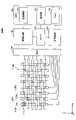
- the proximity detection device 100 includes a proximity detection section 110, a MUX (multiplexer) 120, a transmission circuit 130, a reception circuit 140, a timer 145, and an MPU (Micro Processing Unit) 150.
- the MUX 120, the transmission circuit 130, and the MPU 150 are an example of a signal applying section.
- the signal applying unit applies a plurality of signals with different frequencies to at least one of the first electrode 111 and the second electrode 112, thereby causing the proximity detection unit 110 to perform capacitance detection, ultrasonic transmission and/or ultrasonic reception. It is what makes you do.
- the proximity detection device 100 has an operation surface 100A.
- the operation surface 100A serves as a reference surface when the proximity detection device 100 detects the proximity of an object, and is, for example, the surface of a panel such as a housing of an electronic device including the proximity detection device 100.
- the electronic device may be, for example, an electronic device including a touch panel, such as a smart phone or a tablet computer.
- Proximity detection unit 110 is positioned on the back side of operation surface 100A, and operation surface 100A is positioned on the front side of proximity detection unit 110 .
- a case where the object is the hand of the user of the electronic device including the proximity detection device 100 will be described.
- the proximity detection device 100 detects proximity of the user's hand to the operation surface 100A.
- proximity refers to approaching the operation surface 100A without touching the operation surface 100A or touching the operation surface 100A.
- the proximity detection device 100 detects the amount of charge corresponding to the capacitance between the hand and the proximity detection unit 110, and performs profile and image detection based on the amount of charge to detect the position of the hand, which is the object. calculate.
- Calculation of the position of the hand based on the capacitance includes the position of the hand in contact with (touching) the operation surface 100A and the position of the hand in a state in which the hand is not in contact with the operation surface 100A but is very close to the operation surface 100A. It means that it is possible to calculate the position of The position of the hand calculated based on the capacitance can be represented three-dimensionally.
- the proximity detection device 100 transmits ultrasonic waves from a plurality of locations of the proximity detection unit 110 toward the hand, and based on the round-trip time until the reflected waves are received, the distance from the operation surface 100A to the plurality of points on the hand. Calculate distance. That is, the proximity detection unit 110 performs ultrasonic wave reception using reflected waves after ultrasonic wave transmission. The proximity detection device 100 can further calculate the hand position distribution from the calculated distances.
- the proximity detection device 100 calculates the distance from the operation surface 100A to the hand using ultrasonic waves, If it is less than the distance, the distance to the hand is calculated using capacitance.
- a predetermined distance for example, a plurality of distances from the operation surface 100A to a plurality of points on the hand are obtained based on the round trip time of the ultrasonic wave. , whether or not the average value of a plurality of distances is longer than a predetermined distance.
- the predetermined distance is, for example, 3 cm to 10 cm. Also, instead of the average value of a plurality of distances, it may be determined whether the minimum value of a plurality of distances is longer than a predetermined distance, or whether the distance at a certain point is longer than a predetermined distance. good too.
- the proximity detection device 100 displays a two-dimensional profile representing a two-dimensional distribution of hand shapes, or a three-dimensional distribution of hand shapes.
- a three-dimensional image can be calculated.
- Such a two-dimensional profile or three-dimensional image of the shape of the hand can be calculated particularly based on the round-trip time from transmitting ultrasonic waves from multiple locations of the proximity detection unit 110 to receiving reflected waves. to multiple points on the hand.
- the two-dimensional profile of the shape of the hand is, for example, the XZ plane at a certain Y coordinate, or the position of the hand obtained from the distribution of the distances in the Z direction from the operation surface 100A to a plurality of positions of the hand on the YZ plane at a certain X coordinate.
- the three-dimensional image of the shape of the hand represents the three-dimensional distribution of hand positions obtained from the distribution of distances in the Z direction from the operation surface 100A to a plurality of positions of the hand.
- the proximity detection device 100 is designed to share a detection unit that detects the distance to the hand using ultrasonic waves and detects the position of the hand using capacitance.
- Circuit 130, receiver circuit 140, timer 145, and MPU 150 are used.
- the proximity detection unit 110 has a piezoelectric body, and a first electrode and a second electrode provided to contact the piezoelectric body, and detects proximity of an object.
- the term "piezoelectric body” as used herein refers to a substance having piezoelectricity, and for example, an electret having piezoelectricity is also included in the piezoelectric body.
- the proximity detector 110 has a first electrode 111, a second electrode 112, a piezoelectric body 113, and a substrate 114, and detects the proximity of a hand as an object.
- the first electrodes 111 are linear electrodes (electrode lines) extending in the X direction, and a plurality of first electrodes 111 are arranged at regular intervals in the Y direction.
- the X direction is an example of a first direction
- the Y direction is an example of a second direction.
- the second electrodes 112 are linear electrodes (electrode lines) extending in the Y direction, and a plurality of second electrodes 112 are arranged at regular intervals in the X direction.
- the first electrode 111 and the second electrode 112 intersect in plan view with a gap in the Z direction.
- a piezoelectric body 113 is provided. That is, the first electrode 111 and the second electrode 112 are provided so as to be in contact with the piezoelectric body 113, and the first electrode 111 and the second electrode 112 are configured to sandwich the piezoelectric body 113 therebetween. .
- the first electrode 111 and the second electrode 112 are used for both detection of the distance to the hand using ultrasonic waves and detection of the position of the hand using capacitance.
- the piezoelectric body 113 is used for detecting the distance to the hand using ultrasonic waves.
- the proximity detection unit 110 also has a function of ultrasonic wave detection by having the electrode for capacitance detection also serve as the electrode of the piezoelectric body.
- Intersections 110A where the first electrodes 111 and the second electrodes 112 intersect in plan view are arranged in a matrix as shown in FIG. Since the substrate 114 is provided on the upper side of the first electrode 111 and the lower side of the second electrode 112, as shown in FIG. It has a structure in which a second electrode 112, a piezoelectric body 113, a first electrode 111, and a substrate 114 are laminated.
- the first electrode 111 and the second electrode 112 may be linear electrodes made of metal such as copper or aluminum.
- a substrate 114 having a plurality of first electrodes 111 formed on one surface and a substrate 114 having a plurality of second electrodes 112 formed on one surface are prepared.
- the proximity detection unit 110 can be manufactured by sandwiching and pasting two substrates 114 .
- the piezoelectric body 113 is arranged between the first electrode 111 and the second electrode 112, but the first electrode 111 and the second electrode 112 are insulated by an insulating layer or the like at the crossing portion 110A. It is good if there is
- the piezoelectric body 113 is provided to generate ultrasonic vibrations.
- the reason why ultrasonic waves are used is that by radiating highly directional ultrasonic waves directly above each piezoelectric body 113 (in the +Z direction), it is easy to measure the distance to the hand positioned directly above the piezoelectric body 113 . be.
- the piezoelectric body 113 for example, an element such as a piezo element that causes strain by applying a voltage can be used.
- the piezoelectric body 113 can be resonated and ultrasonic waves can be transmitted directly above the piezoelectric body 113 .
- the AC signal for ultrasonic waves is an example of a second frequency signal for transmitting ultrasonic waves, and any frequency that can resonate the piezoelectric body 113 arranged between the first electrode 111 and the second electrode 112 can be used. good.
- the frequency of the AC signal for ultrasonic waves is, for example, several tens of kHz to several hundred kHz, and the piezoelectric body 113 vibrates at a frequency equal to the frequency of the AC signal.
- the piezoelectric body 113 can be resonated to generate ultrasonic waves of a desired frequency.
- an electret having piezoelectricity may be used instead of the piezoelectric body 113.
- the electret is sandwiched between the first electrode 111 and the second electrode 112 and applied with an AC signal for ultrasonic waves, so that the electret can generate ultrasonic waves in the same manner as the piezoelectric body 113 .
- a flexible or rigid wiring board, an insulating sheet, or the like can be used for the substrate 114 .
- the proximity detector 110 may be made transparent to visible light.
- the first electrode 111 and the second electrode 112 are made of a transparent conductive material such as ITO (Indium Tin Oxide), the piezoelectric body 113 is transparent, and the two substrates 114 are transparent substrates. should be used.
- the MUX 120 is connected to the first electrode 111 and the second electrode 112 via wiring, and is also connected to the transmission circuit 130 and the reception circuit 140 .
- the MUX 120 selects one or more first electrodes 111 from among the plurality of first electrodes 111, and selects one or more second electrodes 112 from among the plurality of second electrodes 112. By selecting , the first electrode 111 and the second electrode 112 connected to the transmission circuit 130 and the reception circuit 140 are switched in time series.
- the MPU 150 switches the selection of the first electrode 111 and the second electrode 112 by the MUX 120 .
- ⁇ Transmitting circuit 130> When the transmission circuit 130 detects the distance to the hand using ultrasonic waves, the transmission circuit 130 is controlled by the MPU 150 to provide ultrasonic waves between the first electrodes 111 and the second electrodes 112 via the MUX 120 . While outputting an AC signal, it outputs an AC signal to the timer 145 . In addition, when performing position detection by electrostatic capacitance, the transmission circuit 130 is controlled by the MPU 150 to transmit the electrostatic capacitance detection signal to either the first electrode 111 or the second electrode 112 via the MUX 120 . Outputs an AC signal of the frequency for Detection of the distance to the hand using ultrasonic waves and position detection using capacitance are performed separately, for example, in a time-sharing manner. A signal is selectively applied to either each first electrode 111 or each second electrode 112 .
- the AC signal of the frequency for capacitance detection is an example of a first frequency signal for capacitance detection
- the AC signal for ultrasonic waves is an example of a second frequency signal for ultrasonic transmission.
- the frequency of the AC signal for capacitance detection may be, for example, several tens of kHz to several hundreds of kHz in the same manner as the AC signal for ultrasonic waves. This is to prevent the piezoelectric body 113 from resonating when performing position detection based on capacitance.
- the charge measurement unit is connected to at least one of the first electrode 111 and the second electrode 112 and measures the charge.
- the receiving circuit 140 corresponds to the charge measuring section.
- the receiving circuit 140 is controlled by the MPU 150 to generate waveforms generated by charges of the first electrodes 111 and the second electrodes 112 via the MUX 120. It acquires and outputs to the timer 145 .
- the receiving circuit 140 is controlled by the MPU 150 to receive charges corresponding to the electrostatic capacitance of each of the first electrodes 111 and each of the second electrodes 112 via the MUX 120 . The amount is detected and output to MPU 150 .
- the timer 145 is controlled by the MPU 150 when detecting the distance to the hand using ultrasonic waves, so that each first electrode 111 and each second electrode 112 receives an AC signal input from the transmission circuit 130 .
- the time difference between the waveform and the waveform input from the receiving circuit 140 is measured as the round trip time of the ultrasonic waves.
- the timer 145 outputs the round trip time measured for each first electrode 111 and each second electrode 112 to the MPU 150 .
- the MPU 150 has a main control section 151 , a calculation section 152 and a memory 153 .
- the MPU 150 is implemented by a computer including a CPU (Central Processing Unit), RAM (Random Access Memory), ROM (Read Only Memory), an input/output interface, an internal bus, and the like.
- the main control unit 151 and the calculation unit 152 represent functions of programs executed by the MPU 150 as functional blocks.
- a memory 153 functionally represents the memory of the MPU 150 .
- the main control unit 151 is a processing unit that supervises the processing of the MPU 150, and executes processing other than the processing executed by the calculation unit 152, for example.
- the calculation unit 152 calculates the distance between the object (eg hand) and the proximity detection unit 110 .
- the MPU 150 switches the selection of the first electrode 111 and the second electrode 112 by the MUX 120 when detecting the distance to the hand using ultrasonic waves and when detecting the position using capacitance. Since the MPU 150 is connected to the first electrode 111 and the second electrode 112 selected by the MUX 120, the calculation unit 152 receives the first electrode 111 and the It will be connected to the second electrode 112 .
- the signal applying unit selectively applies a first frequency signal for capacitance detection and a second frequency signal for ultrasonic wave transmission.
- the calculation unit 152 obtains the result of capacitance detection and/or ultrasonic detection based on the signal selected by the signal application unit and the charge measured by the reception circuit 140 (charge measurement unit). Based on the result obtained, the distance between the object and the proximity detection unit 110 is calculated. Specifically, when the signal application unit selects the first frequency signal, the calculation unit 152 obtains the capacitance detection result based on the amount of charge measured by the reception circuit 140, and obtains the obtained Based on the result, the distance between the object and the proximity detector 110 is calculated.
- the calculation unit 152 detects the proximity to the object based on the time from the transmission of the ultrasonic wave to the reception of the ultrasonic wave based on the charge measured by the receiving circuit 140.
- the distance between the unit 110 is calculated. That is, the calculation unit 152 uses the charge amount of the first electrode 111 and/or the second electrode 112 measured by the charge measurement unit (receiving circuit 140) to calculate the results of both electrostatic capacitance detection and ultrasonic detection. It can be said that it is a common calculation part that can be judged.
- the signal application unit selects the second frequency signal to cause the proximity detection unit 110 to transmit and/or receive ultrasonic waves, and the distance between the object calculated by the calculation unit 152 and the proximity detection unit 110 is calculated. becomes equal to or less than a predetermined distance, the first frequency signal is selected to cause the proximity detection unit 110 to perform capacitance detection.
- the MPU 150 controls the transmission circuit 130 while switching the selection of the first electrode 111 and the second electrode 112 by the MUX 120 in time series to , an AC signal for ultrasound is output between and, and a round-trip time is obtained from the timer 145 .
- the calculation unit 152 calculates the distance from the operation surface 100A directly above each intersection 110A to each part of the hand.
- the distance to the hand is calculated using ultrasonic waves.
- the calculation unit 152 causes the proximity detection unit 110 to detect the position of the object by the capacitance. Calculate. It should be noted that the average value of all distances is not necessarily used for determination, and the minimum value of all distances may be used for determination, or based on the distance between the object and the proximity detection unit 110 at a certain point. A determination may be made as to whether or not the distance is equal to or less than a predetermined distance.
- the timer 145 is provided separately from the MPU 150, but the MPU 150 itself may have the function of measuring time, in which case the timer 145 need not be provided.
- the MPU 150 When detecting the distance to the hand using ultrasonic waves, the MPU 150 switches the selection of the first electrode 111 and the second electrode 112 by the MUX 120 in time series, and controls the transmission circuit 130 to detect each first electrode.
- An AC signal for ultrasonic waves is output between 111 and each of the second electrodes 112 , a waveform generated by the charge is acquired by the receiving circuit 140 , and a round trip time is acquired from the timer 145 .
- the calculation unit 152 obtains the distance from the operation surface 100A to the point where the ultrasonic wave is reflected based on the round trip time and the speed of sound.
- the point where the ultrasonic wave is reflected is the part of the hand located directly above the piezoelectric body 113 at the intersection 110A of the first electrode 111 and the second electrode 112 selected by the MUX 120 .
- the calculation unit 152 may further detect a two-dimensional profile of the hand shape or a three-dimensional image of the hand shape based on the obtained distance. Specifically, the calculation unit 152 calculates the two-dimensional profile of the hand, which is the object, based on the charge amount measured by the receiving circuit 140 (charge measurement unit) and/or the time from ultrasonic wave transmission to ultrasonic wave reception, or Detect 3D images. By detecting a two-dimensional profile or a three-dimensional image, it is possible to grasp the shape of the hand and detect the movement of the user's hand.
- the MPU 150 switches the selection of the first electrode 111 and the second electrode 112 by the MUX 120 in time series while controlling the transmission circuit 130 to control the first electrode 111 and each electrode. While outputting an AC signal with a frequency for capacitance detection between the second electrode 112 and controlling the receiving circuit 140, the capacitance obtained from the charge of each first electrode 111 and each second electrode 112 to detect
- the MPU 150 switches between detection of the distance to the hand using ultrasonic waves and position detection using capacitance by time division. You can go while In this case, it can be said that the signal application unit switches between the first frequency signal and the second frequency signal by time division.
- detection of the distance to the hand using ultrasonic waves and detection of the position of the hand using capacitance are always performed regardless of the distance from the operation surface 100A to the hand. be able to.
- the memory 153 stores programs and data necessary for the main control unit 151 and the calculation unit 152 to perform the above-described processing, the round trip time input from the timer 145 to the MPU 150, the distance calculated by the calculation unit 152, the capacitance, the hand data representing a two-dimensional profile or a three-dimensional image of the shape of
- FIG. 3 is a diagram showing a flowchart representing an example of processing executed by the MPU 150. As shown in FIG.
- step S1 calculates the distance from operation surface 100A directly above each intersection 110A to each part of the hand.
- step S1 is executed to determine whether to detect the distance to the hand by ultrasonic waves or to detect the position by capacitance.
- the MPU 150 determines whether the average value of all distances is longer than a predetermined distance (step S2).
- the MPU 150 determines that the average value of all distances is longer than the predetermined distance (S2: YES), it detects the distance to the hand using ultrasonic waves (step S3). This is because the position of the hand is too far to be detected by capacitance, and is calculated based on the round-trip time of the ultrasonic waves. Since the details of the detection of the distance to the hand using ultrasonic waves have been described above, they are omitted here.
- the calculation unit 152 detects a two-dimensional profile or a three-dimensional image of the shape of the hand based on the distance obtained in step S2 (step S4). This provides a two-dimensional profile or three-dimensional image of the hand approaching the operating surface 100A.
- step S5 the MPU 150 determines whether or not to finish the series of processes. It is determined in step S5 that the series of processes is finished, for example, when the power of the electronic device equipped with the proximity detection device 100 is turned off.
- step S6 when the MPU 150 determines in step S2 that the average value of all the distances is not longer than the predetermined distance (S2: NO), it performs position detection using capacitance (step S6). This is because the position of the hand is close to being determined by the reciprocating time of the ultrasonic wave, so it is determined by the capacitance. It should be noted that the MPU 150 advances the flow to step S5 after finishing the process of step S6.
- the proximity detection device 100 provides the piezoelectric body 113 at the intersection 110A between the first electrode 111 and the second electrode 112, and when the position of the hand is within a predetermined distance, the first electrode 111 and Position detection is performed using the electrostatic capacitance obtained from the charge of the second electrode 112.
- the piezoelectric body 113 is driven to detect the distance to the hand based on the round-trip time of the transmitted ultrasonic waves. Calculate the distance. Detection of the distance to the hand using ultrasonic waves can detect a distance that is too far to be realized by position detection using capacitance.
- the proximity detection device 100 having a detection distance capable of detecting an object that is some distance away from the operation surface 100A.
- the proximity detection device 100 is intended to share a detection unit that detects the distance to the hand using ultrasonic waves and detects the position of the hand using capacitance.
- Common detectors are MUX 120 , transmitter circuit 130 , receiver circuit 140 , timer 145 and MPU 150 .
- the receiving circuit 140 can perform charge detection commonly required for both electrostatic capacitance detection and ultrasonic detection with a single configuration by serving as a charge measuring unit. Therefore, the detection of the distance to the hand using ultrasonic waves and the detection of the position of the hand using capacitance can be performed by the same circuit. It is possible to obtain the position of the hand and the position of the hand some distance away from the operation surface 100A using ultrasonic waves.
- detection of the distance to the hand by ultrasonic waves and detection of the position of the hand by electrostatic capacitance are performed by the same detection unit, so that the detection accuracies of the two different detection methods can be made uniform.
- the proximity detection unit 110 is configured such that the first electrode 111 and the second electrode 112 sandwich the piezoelectric body 113 therebetween, the first electrode 111 and the second electrode 112 for capacitance detection are Using this, an AC signal can be easily applied to the piezoelectric body 113 .
- the proximity detection unit 110 may be configured such that the first electrode 111 and the second electrode 112 sandwich an electret having piezoelectricity therebetween.
- the MUX 120, the transmission circuit 130, the reception circuit 140, and the MPU 150 connected to the first electrode 111 and the second electrode 112 are used for capacitance detection, a timer 145 is added and the MPU 150 executes Proximity detection device 100 capable of ultrasonic detection can be realized only by changing the program. This is a solution to the problem that if the distance to the hand is detected by ultrasonic waves and the position of the hand is detected by capacitance using separate proximity detection units, the device configuration becomes complicated and large. .
- the proximity detection unit 110 receives ultrasonic waves using reflected waves after transmitting ultrasonic waves, there is no need to provide separate proximity detection units for transmission and reception. Sound waves can be transmitted and received, and ultrasonic waves can be transmitted and received with a simple configuration.
- the signal applying unit selectively applies the first frequency signal for capacitance detection and the second frequency signal for ultrasonic wave transmission.
- the MPU 150, MUX 120, and transmission circuit 130 corresponding to the signal application unit selectively apply an AC signal for capacitance detection and an AC signal for ultrasonic wave transmission.
- the calculation unit 152 obtains the result of capacitance detection and/or ultrasonic detection based on the signal selected by the signal application unit (MPU 150, MUX 120, and transmission circuit 130) and the measured charge, and Based on the results obtained, the distance between the hand, which is the object, and the proximity detection unit 110 is calculated. Therefore, it is possible to realize a simple configuration in which one MUX 120, one transmission circuit 130, and one reception circuit 140 can be used for both capacitance detection and ultrasonic detection.
- the signal application unit selects an AC signal for transmitting ultrasonic waves, causes the proximity detection unit 110 to transmit and receive ultrasonic waves, and the calculation unit 152 calculates When the distance between the object and the proximity detection unit 110 becomes equal to or less than a predetermined distance, an AC signal for capacitance detection is selected to cause the proximity detection unit 110 to detect capacitance.
- an AC signal for capacitance detection is selected to cause the proximity detection unit 110 to detect capacitance.
- a simple configuration can be realized in which the proximity detection unit 110, one MUX 120, one transmission circuit 130, and one reception circuit 140 can be used for both capacitance detection and ultrasonic detection.
- a timer 145 that measures the time (round-trip time) from when the transmission circuit 130 applies the second frequency signal until the reception circuit 140 measures the charge based on the AC signal for ultrasonic wave transmission reflected by the object.
- the calculation unit 152 calculates the distance between the object and the proximity detection unit 110 based on the time measured by the timer 145. Therefore, based on the round trip time of the ultrasonic wave, the object is The distance to the hand can be easily detected.
- the transmission circuit 130 and the reception circuit 140 can switch between the AC signal for capacitance detection and the AC signal for ultrasonic wave detection by time division, one transmission circuit 130 and one reception circuit 140 can be switched. can be used for both electrostatic capacitance detection and ultrasonic detection in a time division manner.
- the proximity detection unit 110 only needs to include one piezoelectric body 113 and one first electrode 111 and one second electrode 112 provided to contact the piezoelectric body 113.
- the plurality of first electrodes 111 and the plurality of second electrodes 112 are not necessarily required as shown in FIG.
- distance data at a plurality of points are required. Therefore, as described in FIG.
- An electrode 111 and a plurality of second electrodes 112 may be provided.
- a plurality of first electrodes 111, one or more piezoelectric bodies 113, and a plurality of second electrodes 112 are provided, and each of the one or more piezoelectric bodies 113 is at least Since it is provided between any one of the plurality of second electrodes 112 and at least one of the plurality of second electrodes 112, one or more piezoelectric bodies 113 provided between the plurality of first electrodes 111 and the plurality of second electrodes 112
- a sheet layer of the piezoelectric body 113 is provided over the entire surface between the layer provided with the first electrode 111 and the layer provided with the second electrode 112. is the case.
- the first electrodes 111 extend in the X direction and are arranged in a plurality in the Y direction intersecting the X direction.
- the second electrodes 112 extend in the Y direction and are arranged in a plurality in the X direction. Since it is provided so as to be sandwiched between the first electrode 111 and the second electrode 112 at the intersection portion 110A where the first electrode 111 and the second electrode 112 intersect, the first electrode 111 and the second electrode for capacitance detection are provided. 112, it is possible to easily apply an AC signal for transmitting ultrasonic waves to the piezoelectric body 113 and easily detect a reflected wave.
- the capacitance detection may be performed by self-capacitance detection or by mutual capacitance detection.
- the first electrode 111 and the second electrode 112 do not necessarily have to intersect. The arrangement may be such that they are arranged side by side.
- a proximity detection device 100 can be provided. That is, the proximity detection device 100 uses both electrostatic capacitance detection and ultrasonic detection to perform detailed image detection of an object, and performs electrostatic capacitance detection in a region close to a touch and ultrasonic detection in a region away from a touch. Doing so in an area can enable object detection at a wide range of distances.
- the proximity detection unit 110 has a plurality of first electrodes 111, a plurality of second electrodes 112, and one or more piezoelectric bodies 113.
- the proximity detection unit 110 has a minimum As a configuration, a configuration having one first electrode 111, one second electrode 112, and one piezoelectric body 113 may be employed. The number of first electrodes 111 and the number of second electrodes 112 may not be equal.
- the piezoelectric body 113 is provided at each of the intersections 110A between the plurality of first electrodes 111 and the plurality of second electrodes 112.
- the intersections 110A at which the piezoelectric bodies 113 are provided It may be a part of all intersections 110A.
- the piezoelectric bodies 113 may be provided at every other intersection 110A in the X direction and/or the Y direction.
- the number of piezoelectric bodies 113 is related to hand position detection, two-dimensional profile, and three-dimensional image resolution in ultrasonic detection, so the number may be appropriately set according to the application of the proximity detection device 100 .
- each of the one or more piezoelectric bodies 113 may be provided between at least one of the multiple first electrodes 111 and at least one of the multiple second electrodes 112 .
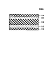
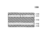
- FIGS. 4A to 7C show a configuration corresponding to a cross section corresponding to the cross section 110A shown in FIG. 2 (a cross section taken along line AA in FIG. 1).
- the intersection 110A shown in FIG. 2 may be modified to any of the configurations shown in FIGS. 4A to 7C.
- the intersection 110A in FIG. 4A has a first electrode 111, a second electrode 112, a piezoelectric body 113, and a substrate 114.
- the intersection 110A of FIG. 4A has a configuration in which the uppermost substrate 114 of the intersection 110A shown in FIG. 2 is omitted.
- the piezoelectric body 113 and the first electrode 111 may be stacked on the substrate 114 having the second electrode 112 formed on one surface thereof.
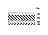
- the intersection 110A of FIG. 4B has a first electrode 111, a second electrode 112, a piezoelectric body 113, and two substrates 114, and has a configuration in which the piezoelectric bodies 113 of the intersection 110A shown in FIG. 2 are thinned.
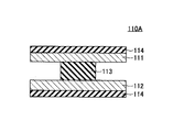
- the crossing portion 110A of FIG. 4C has a first electrode 111, a second electrode 112, a piezoelectric body 113, and two substrates 114, and the first electrode 111 and the second electrode 112 of the crossing portion 110A shown in FIG. It has a narrowed configuration.
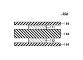
- the intersection 110A of FIG. 4D has a first electrode 111, a second electrode 112, a piezoelectric body 113, and two substrates 114, and the piezoelectric body 113 of the intersection 110A shown in FIG. 2 is divided into two.
- first electrode 111 has a first electrode 111, a second electrode 112, a piezoelectric body 113, and two substrates 114.
- first electrode of the intersection 110A shown in FIG. 111 is divided into two.
- the first electrode 111 may be divided into two pieces, or, for example, the first electrode 111 may have a spiral shape in plan view.
- the intersection 110A in FIG. 5B has a first electrode 111, a second electrode 112, a piezoelectric body 113, and two substrates 114, and has a configuration in which the piezoelectric body 113 shown in FIG. 5A is divided into two.
- the intersection 110A shown in FIG. 5C has a first electrode 111, a second electrode 112, a piezoelectric body 113, two substrates 114, and a shield electrode 115.
- the shield electrode 115 is an example of a third electrode for shielding. 5C, the second electrode 112 is arranged on the piezoelectric body 113 together with the first electrode 111, the shield electrode 115 is formed on the lower substrate 114, and the shield electrode 115 A piezoelectric body 113 is provided on the .
- the shield electrode 115 is provided on the side of the first electrode 111 and the second electrode 112 opposite to the side of the operation surface 100A on which the hand, which is the object, approaches.
- the first electrode 111 and the second electrode 112 are electrodes patterned in a diamond shape in plan view, and the bridge portion where the first electrode 111 and the second electrode 112 straddle each other is omitted in FIG. 5C.
- the shield electrode 115 is provided for shielding the first electrode 111 and the second electrode 112 on the operation surface 100A side from noise and for suppressing parasitic capacitance between the electrode and the ground. , or may be connected to ground.
- the signal applying section applies the third frequency signal to the third electrode (shield electrode 115).
- the signal applying unit can also cause the shield electrode 115 to function as an active shield by setting the frequency of the third frequency signal to be the same as the frequency of the first frequency signal when performing capacitance detection.
- the shield electrode 115 is composed of, for example, a metal foil made of copper or aluminum, or a conductive film made of a transparent conductive material such as an ITO film.
- the shield electrode 115 is a single electrode provided over the entire proximity detection unit 110 in plan view. An AC voltage is applied to the shield electrode 115 as described above when the position of the hand is detected by electrostatic capacitance.
- the crossing portion 110A shown in FIG. 5D has a configuration in which the piezoelectric body 113 of the crossing portion 110A shown in FIG. 5C is divided into a first electrode 111 and a second electrode 112.
- the first electrode 111 may transmit ultrasound and the second electrode 112 may receive ultrasound.
- the crossing portion 110A shown in FIG. 6A has a configuration obtained by removing the piezoelectric body 113 below the second electrode 112 from the crossing portion 110A shown in FIG. 5D.
- the crossing portion 110A shown in FIG. 6B has a configuration in which the first electrode 111 and the second electrode 112 of the crossing portion 110A shown in FIG. 6A are thinned.
- the intersection 110A shown in FIG. 7A has a first electrode 111, a second electrode 112, a piezoelectric body 113, three substrates 114, a shield electrode 115, and an OCA (Optical Clear Adhesive) 116.
- the intersection 110A shown in FIG. 7A has a configuration in which a shield electrode 115, an OCA 116, a substrate 114, a second electrode 112, a piezoelectric body 113, a first electrode 111, and a substrate 114 are stacked on a substrate 114 at the bottom.
- the intersection 110A shown in FIG. 7A is formed by bonding a third substrate 114 having a shield electrode 115 on one surface thereof under the substrate 114 below the intersection 110A shown in FIG. It has a configuration that Shield electrode 115 may be applied with an AC voltage when detecting the position of the hand by electrostatic capacitance, similar to intersection 110A in FIG. 5C.
- the intersection 110A shown in FIG. 7B has a configuration in which the substrate 114 is removed from the top of the intersection 110A shown in FIG. 7A.
- the crossing portion 110A shown in FIG. 7B has a configuration in which a third substrate 114 having a shield electrode 115 provided on one surface thereof is bonded with the OCA 116 under the crossing portion 110A shown in FIG. 4A.
- the crossing portion 110A shown in FIG. 7C has a configuration in which the substrate 114 below the second electrode 112 of the crossing portion 110A shown in FIG. 7A is removed and the substrate 114 provided with the shield electrode 115 is turned upside down.
- the substrate 114 on which the shield electrode 115 is provided may be turned upside down from that shown in FIG.
- FIG. 8 is a diagram showing an example of a proximity detection device 100M according to a modification of the embodiment.
- the proximity detection device 100M includes a proximity detection section 110M instead of the proximity detection section 110 shown in FIG.
- Other configurations are the same as those of the proximity detection device 100 shown in FIG. The differences are explained here.
- the proximity detection unit 110M is used for transmitting ultrasonic waves instead of the configuration in which the piezoelectric bodies 113 are provided at all intersections 110A of the first electrodes 111 and the second electrodes 112 as in the proximity detection unit 110 of FIG.
- a piezoelectric body 113A and a piezoelectric body 113B used for receiving ultrasonic waves are arranged between the first electrode 111 and the second electrode 112 at the intersections 110B1 and 110B2, respectively.
- the intersecting portion 110B1 and the intersecting portion 110B2 are arranged so as to include the first electrodes 111 that are different from each other every other first electrode 111 among the plurality of first electrodes 111 .
- the crossing portion 110B1 and the crossing portion 110B2 are arranged so as to include the first electrodes 111 that are different from each other every other second electrode 112 among the plurality of second electrodes 112 .
- the crossing portion 110B1 and the crossing portion 110B2 are not adjacent to each other in the X direction and the Y direction in a plan view, and are positioned obliquely.
- the piezoelectric body 113A used for transmitting ultrasonic waves and the piezoelectric body 113B used for receiving ultrasonic waves have the same configuration as the piezoelectric body 113 of the proximity detection device 100 .
- the MUX 120 selects the first electrode 111 and the second electrode 112 included in the intersection 110B1 and applies an AC signal for ultrasonic waves. By doing so, an AC signal for ultrasonic waves may be applied to the piezoelectric body 113A.
- the MUX 120 selects the first electrode 111 and the second electrode 112 included in the crossing portion 110B2, and the receiving circuit 140 detects the charges of the first electrode 111 and the second electrode 112. It suffices to acquire the waveform generated by
- the method of performing position detection by electrostatic capacitance in the proximity detection device 100M is the same as the method of performing position detection by electrostatic capacitance in the proximity detection device 100.
- the distance to the hand is detected by ultrasonic waves. This simplifies the switching control of the MUX 120 and the control of waveform acquisition in the receiving circuit 140, and facilitates the performance improvement of the device by separating the transmission and reception functions.
Landscapes
- Engineering & Computer Science (AREA)
- Theoretical Computer Science (AREA)
- General Engineering & Computer Science (AREA)
- Physics & Mathematics (AREA)
- Human Computer Interaction (AREA)
- General Physics & Mathematics (AREA)
- Acoustics & Sound (AREA)
- Multimedia (AREA)
- Signal Processing (AREA)
- Measurement Of Velocity Or Position Using Acoustic Or Ultrasonic Waves (AREA)
- Geophysics And Detection Of Objects (AREA)
- Switches That Are Operated By Magnetic Or Electric Fields (AREA)
- Measuring Pulse, Heart Rate, Blood Pressure Or Blood Flow (AREA)
Priority Applications (5)
| Application Number | Priority Date | Filing Date | Title |
|---|---|---|---|
| JP2023517106A JP7697190B2 (ja) | 2021-04-30 | 2022-03-03 | 近接検出装置 |
| DE112022002381.3T DE112022002381T5 (de) | 2021-04-30 | 2022-03-03 | Annäherungserfassungsvorrichtung |
| CN202280020983.8A CN117099073A (zh) | 2021-04-30 | 2022-03-03 | 接近检测装置 |
| US18/479,639 US12386464B2 (en) | 2021-04-30 | 2023-10-02 | Proximity detection device |
| JP2025086043A JP2025114868A (ja) | 2021-04-30 | 2025-05-23 | 近接検出装置 |
Applications Claiming Priority (2)
| Application Number | Priority Date | Filing Date | Title |
|---|---|---|---|
| JP2021077787 | 2021-04-30 | ||
| JP2021-077787 | 2021-04-30 |
Related Child Applications (1)
| Application Number | Title | Priority Date | Filing Date |
|---|---|---|---|
| US18/479,639 Continuation US12386464B2 (en) | 2021-04-30 | 2023-10-02 | Proximity detection device |
Publications (1)
| Publication Number | Publication Date |
|---|---|
| WO2022230358A1 true WO2022230358A1 (ja) | 2022-11-03 |
Family
ID=83846964
Family Applications (1)
| Application Number | Title | Priority Date | Filing Date |
|---|---|---|---|
| PCT/JP2022/009264 Ceased WO2022230358A1 (ja) | 2021-04-30 | 2022-03-03 | 近接検出装置 |
Country Status (6)
| Country | Link |
|---|---|
| US (1) | US12386464B2 (https=) |
| JP (2) | JP7697190B2 (https=) |
| CN (1) | CN117099073A (https=) |
| DE (1) | DE112022002381T5 (https=) |
| TW (1) | TWI820590B (https=) |
| WO (1) | WO2022230358A1 (https=) |
Cited By (1)
| Publication number | Priority date | Publication date | Assignee | Title |
|---|---|---|---|---|
| WO2025142329A1 (ja) * | 2023-12-26 | 2025-07-03 | 株式会社村田製作所 | 押圧センサ、押圧点検出方法、及び押圧点検出プログラム |
Families Citing this family (1)
| Publication number | Priority date | Publication date | Assignee | Title |
|---|---|---|---|---|
| CN117871970B (zh) * | 2024-03-11 | 2024-05-10 | 北京理工大学 | 一种具有有源屏蔽电路的静电传感器装置 |
Citations (8)
| Publication number | Priority date | Publication date | Assignee | Title |
|---|---|---|---|---|
| US20160054826A1 (en) * | 2012-07-26 | 2016-02-25 | Apple Inc. | Ultrasound-Based Force Sensing |
| JP2018506089A (ja) * | 2016-01-19 | 2018-03-01 | 北京小米移動軟件有限公司Beijing Xiaomi Mobile Software Co.,Ltd. | ジェスチャーの識別方法及び装置 |
| WO2018139194A1 (ja) * | 2017-01-25 | 2018-08-02 | 株式会社村田製作所 | 超音波装置 |
| WO2018159460A1 (ja) * | 2017-03-03 | 2018-09-07 | アルプス電気株式会社 | 入力装置とその制御方法 |
| JP2019194791A (ja) * | 2018-05-02 | 2019-11-07 | Nissha株式会社 | 押圧力測定を備えたタッチパネル |
| JP2019532432A (ja) * | 2016-10-12 | 2019-11-07 | クアルコム,インコーポレイテッド | ハイブリッドの静電容量感知および超音波感知 |
| US20200184176A1 (en) * | 2018-12-07 | 2020-06-11 | Butterfly Network, Inc. | Ultrasound fingerprint detection and related apparatus and methods |
| JP2020530622A (ja) * | 2017-08-09 | 2020-10-22 | ザ ボード オブ トラスティーズ オブ ザ レランド スタンフォード ジュニア ユニバーシティー | 対話型生体タッチスキャナ |
Family Cites Families (24)
| Publication number | Priority date | Publication date | Assignee | Title |
|---|---|---|---|---|
| JP4863993B2 (ja) * | 2005-05-31 | 2012-01-25 | 日本碍子株式会社 | 物体の通過検出装置 |
| US8723827B2 (en) * | 2009-07-28 | 2014-05-13 | Cypress Semiconductor Corporation | Predictive touch surface scanning |
| US8698769B2 (en) * | 2011-08-01 | 2014-04-15 | Sharp Kabushiki Kaisha | Dual mode capacitive touch panel |
| WO2014018119A1 (en) | 2012-07-26 | 2014-01-30 | Changello Enterprise Llc | Ultrasound-based force and touch sensing |
| US9983715B2 (en) * | 2012-12-17 | 2018-05-29 | Apple Inc. | Force detection in touch devices using piezoelectric sensors |
| US10478858B2 (en) * | 2013-12-12 | 2019-11-19 | Qualcomm Incorporated | Piezoelectric ultrasonic transducer and process |
| US9501167B2 (en) * | 2014-10-22 | 2016-11-22 | Synaptics Incorporated | Scanned piezoelectric touch sensor device |
| WO2016122173A1 (ko) * | 2015-01-27 | 2016-08-04 | 엘지이노텍 주식회사 | 터치 윈도우 |
| US10497748B2 (en) | 2015-10-14 | 2019-12-03 | Qualcomm Incorporated | Integrated piezoelectric micromechanical ultrasonic transducer pixel and array |
| US10127425B2 (en) | 2017-01-12 | 2018-11-13 | Qualcomm Incorporated | Dual-mode capacitive and ultrasonic fingerprint and touch sensor |
| GB201804129D0 (en) * | 2017-12-15 | 2018-05-02 | Cirrus Logic Int Semiconductor Ltd | Proximity sensing |
| KR102471819B1 (ko) * | 2018-06-21 | 2022-11-29 | 삼성전자 주식회사 | 압전 소자를 이용하여, 압력 감지 및 초음파 신호를 송수신하는 센서 모듈을 포함하는 전자 장치 |
| US20200158556A1 (en) | 2018-11-21 | 2020-05-21 | Elliptic Laboratories As | Power management |
| US10929636B2 (en) * | 2019-01-18 | 2021-02-23 | Qualcomm Incorporated | Ultrasonic fingerprint sensor with electrically nonconductive acoustic layer |
| KR102662218B1 (ko) * | 2019-06-17 | 2024-05-02 | 엘지디스플레이 주식회사 | 초음파 센서 및 디스플레이 장치 |
| US11580204B2 (en) * | 2019-06-26 | 2023-02-14 | Qualcomm Incorporated | Dual-frequency ultrasonic sensor system with frequency splitter |
| US11438703B2 (en) * | 2019-06-27 | 2022-09-06 | Qualcomm Incorporated | Ultrasonic sensor array |
| CN110286738B (zh) * | 2019-06-29 | 2021-06-08 | Oppo广东移动通信有限公司 | 指纹采集方法及相关产品 |
| KR20210052785A (ko) * | 2019-10-31 | 2021-05-11 | 삼성디스플레이 주식회사 | 표시 장치 |
| JP7395972B2 (ja) | 2019-11-11 | 2023-12-12 | 住友電気工業株式会社 | 炭化珪素半導体装置 |
| JP7424069B2 (ja) * | 2020-01-21 | 2024-01-30 | セイコーエプソン株式会社 | 超音波デバイス及び超音波センサー |
| US11592423B2 (en) * | 2020-01-29 | 2023-02-28 | Qeexo, Co. | Adaptive ultrasonic sensing techniques and systems to mitigate interference |
| US11281881B2 (en) * | 2020-05-05 | 2022-03-22 | Qualcomm Incorporated | Device including an ultrasonic fingerprint sensor and a coulomb force apparatus |
| JP7562226B2 (ja) * | 2021-03-23 | 2024-10-07 | パナソニックオートモーティブシステムズ株式会社 | 検出装置、検出システム、および検出方法 |
-
2022
- 2022-01-27 TW TW111103525A patent/TWI820590B/zh active
- 2022-03-03 DE DE112022002381.3T patent/DE112022002381T5/de active Pending
- 2022-03-03 WO PCT/JP2022/009264 patent/WO2022230358A1/ja not_active Ceased
- 2022-03-03 CN CN202280020983.8A patent/CN117099073A/zh active Pending
- 2022-03-03 JP JP2023517106A patent/JP7697190B2/ja active Active
-
2023
- 2023-10-02 US US18/479,639 patent/US12386464B2/en active Active
-
2025
- 2025-05-23 JP JP2025086043A patent/JP2025114868A/ja active Pending
Patent Citations (8)
| Publication number | Priority date | Publication date | Assignee | Title |
|---|---|---|---|---|
| US20160054826A1 (en) * | 2012-07-26 | 2016-02-25 | Apple Inc. | Ultrasound-Based Force Sensing |
| JP2018506089A (ja) * | 2016-01-19 | 2018-03-01 | 北京小米移動軟件有限公司Beijing Xiaomi Mobile Software Co.,Ltd. | ジェスチャーの識別方法及び装置 |
| JP2019532432A (ja) * | 2016-10-12 | 2019-11-07 | クアルコム,インコーポレイテッド | ハイブリッドの静電容量感知および超音波感知 |
| WO2018139194A1 (ja) * | 2017-01-25 | 2018-08-02 | 株式会社村田製作所 | 超音波装置 |
| WO2018159460A1 (ja) * | 2017-03-03 | 2018-09-07 | アルプス電気株式会社 | 入力装置とその制御方法 |
| JP2020530622A (ja) * | 2017-08-09 | 2020-10-22 | ザ ボード オブ トラスティーズ オブ ザ レランド スタンフォード ジュニア ユニバーシティー | 対話型生体タッチスキャナ |
| JP2019194791A (ja) * | 2018-05-02 | 2019-11-07 | Nissha株式会社 | 押圧力測定を備えたタッチパネル |
| US20200184176A1 (en) * | 2018-12-07 | 2020-06-11 | Butterfly Network, Inc. | Ultrasound fingerprint detection and related apparatus and methods |
Cited By (1)
| Publication number | Priority date | Publication date | Assignee | Title |
|---|---|---|---|---|
| WO2025142329A1 (ja) * | 2023-12-26 | 2025-07-03 | 株式会社村田製作所 | 押圧センサ、押圧点検出方法、及び押圧点検出プログラム |
Also Published As
| Publication number | Publication date |
|---|---|
| JP7697190B2 (ja) | 2025-06-24 |
| TW202244698A (zh) | 2022-11-16 |
| US12386464B2 (en) | 2025-08-12 |
| DE112022002381T5 (de) | 2024-02-15 |
| US20240028165A1 (en) | 2024-01-25 |
| JP2025114868A (ja) | 2025-08-05 |
| JPWO2022230358A1 (https=) | 2022-11-03 |
| CN117099073A (zh) | 2023-11-21 |
| TW202401222A (zh) | 2024-01-01 |
| TWI820590B (zh) | 2023-11-01 |
Similar Documents
| Publication | Publication Date | Title |
|---|---|---|
| JP2025114868A (ja) | 近接検出装置 | |
| US10466852B2 (en) | Touch 3D-signal input equipment and multi-function touch panel | |
| CN100356304C (zh) | 接近位置输入装置 | |
| US20090255737A1 (en) | Device and Method for Preventing the Influence of Conducting Material from Point Detection of Projected Capacitive Touch Panel | |
| US9292115B2 (en) | Apparatus and method for detecting user input | |
| JP6573659B2 (ja) | ジェスチャ検出および追跡のための電極配列 | |
| KR102268788B1 (ko) | 측면에 압력센서 및 터치센서를 구비한 휴대용 단말기 | |
| US20100231530A1 (en) | Touch pad for multiple sensing | |
| EP3646956B1 (en) | A phased array ultrasound apparatus, a system for user interaction and a method for forming a combined ultrasonic wave based on a phased array ultrasound apparatus | |
| CN110297559B (zh) | 电子设备及压力信息获取方法 | |
| US20160011708A1 (en) | Multi-axis input device and multi-axis input apparatus | |
| US9733760B2 (en) | In-cell touch type display device, touch circuit, display driver, and in-cell touch type display device driving method | |
| JP2013015976A (ja) | 多機能センサ | |
| CN107426434A (zh) | 输入装置和电子设备 | |
| TWI603243B (zh) | 具有壓力偵測的觸控總成及其驅動方法 | |
| JP2010055614A (ja) | マルチタッチセンサー装置 | |
| EP3141988B1 (en) | In-cell touch type display device | |
| CN205353969U (zh) | 一种具有压力侦测的触控总成 | |
| EP2128743A1 (en) | Touch screen apparatus | |
| CN101874231A (zh) | 多点触摸屏及触摸检测方法 | |
| CN117677990A (zh) | 用于双向指纹感测相关应用的超声指纹传感器技术和方法 | |
| CN108268156A (zh) | 具有指纹识别功能的触摸屏及电子装置 | |
| TWI921684B (zh) | 鄰近檢測裝置 | |
| KR20160086689A (ko) | 바디 터치 디바이스 | |
| CN108268816A (zh) | 具有指纹识别功能的触摸屏及电子装置 |
Legal Events
| Date | Code | Title | Description |
|---|---|---|---|
| 121 | Ep: the epo has been informed by wipo that ep was designated in this application |
Ref document number: 22795281 Country of ref document: EP Kind code of ref document: A1 |
|
| WWE | Wipo information: entry into national phase |
Ref document number: 202280020983.8 Country of ref document: CN |
|
| WWE | Wipo information: entry into national phase |
Ref document number: 2023517106 Country of ref document: JP |
|
| WWE | Wipo information: entry into national phase |
Ref document number: 112022002381 Country of ref document: DE |
|
| 122 | Ep: pct application non-entry in european phase |
Ref document number: 22795281 Country of ref document: EP Kind code of ref document: A1 |