WO2022230176A1 - Engagement structure and coupling member - Google Patents
Engagement structure and coupling member Download PDFInfo
- Publication number
- WO2022230176A1 WO2022230176A1 PCT/JP2021/017211 JP2021017211W WO2022230176A1 WO 2022230176 A1 WO2022230176 A1 WO 2022230176A1 JP 2021017211 W JP2021017211 W JP 2021017211W WO 2022230176 A1 WO2022230176 A1 WO 2022230176A1
- Authority
- WO
- WIPO (PCT)
- Prior art keywords
- coupling member
- shaft portion
- shaft
- axis
- diameter
- Prior art date
Links
- 230000008878 coupling Effects 0.000 title claims abstract description 142
- 238000010168 coupling process Methods 0.000 title claims abstract description 142
- 238000005859 coupling reaction Methods 0.000 title claims abstract description 142
- 230000013011 mating Effects 0.000 claims description 6
- 238000010586 diagram Methods 0.000 description 14
- 238000009413 insulation Methods 0.000 description 11
- 239000000463 material Substances 0.000 description 9
- 239000011347 resin Substances 0.000 description 5
- 229920005989 resin Polymers 0.000 description 5
- 239000004696 Poly ether ether ketone Substances 0.000 description 3
- 239000004642 Polyimide Substances 0.000 description 3
- 238000013459 approach Methods 0.000 description 3
- 238000003780 insertion Methods 0.000 description 3
- 230000037431 insertion Effects 0.000 description 3
- 229920002530 polyetherether ketone Polymers 0.000 description 3
- 229920001721 polyimide Polymers 0.000 description 3
- 239000003380 propellant Substances 0.000 description 3
- 238000007789 sealing Methods 0.000 description 3
- 125000006850 spacer group Chemical group 0.000 description 3
- 239000000853 adhesive Substances 0.000 description 2
- 230000001070 adhesive effect Effects 0.000 description 2
- 230000008020 evaporation Effects 0.000 description 2
- 238000001704 evaporation Methods 0.000 description 2
- 239000006260 foam Substances 0.000 description 2
- 238000012986 modification Methods 0.000 description 2
- 230000004048 modification Effects 0.000 description 2
- 239000004745 nonwoven fabric Substances 0.000 description 2
- 238000010943 off-gassing Methods 0.000 description 2
- 229920000139 polyethylene terephthalate Polymers 0.000 description 2
- 239000005020 polyethylene terephthalate Substances 0.000 description 2
- 230000005855 radiation Effects 0.000 description 2
- 238000012546 transfer Methods 0.000 description 2
- 235000015842 Hesperis Nutrition 0.000 description 1
- UFHFLCQGNIYNRP-UHFFFAOYSA-N Hydrogen Chemical compound [H][H] UFHFLCQGNIYNRP-UHFFFAOYSA-N 0.000 description 1
- 235000012633 Iberis amara Nutrition 0.000 description 1
- 230000006750 UV protection Effects 0.000 description 1
- 230000009471 action Effects 0.000 description 1
- 229910052782 aluminium Inorganic materials 0.000 description 1
- XAGFODPZIPBFFR-UHFFFAOYSA-N aluminium Chemical compound [Al] XAGFODPZIPBFFR-UHFFFAOYSA-N 0.000 description 1
- 230000008901 benefit Effects 0.000 description 1
- 238000000151 deposition Methods 0.000 description 1
- 238000013461 design Methods 0.000 description 1
- 230000000694 effects Effects 0.000 description 1
- 239000012530 fluid Substances 0.000 description 1
- 229910052732 germanium Inorganic materials 0.000 description 1
- GNPVGFCGXDBREM-UHFFFAOYSA-N germanium atom Chemical compound [Ge] GNPVGFCGXDBREM-UHFFFAOYSA-N 0.000 description 1
- PCHJSUWPFVWCPO-UHFFFAOYSA-N gold Chemical compound [Au] PCHJSUWPFVWCPO-UHFFFAOYSA-N 0.000 description 1
- 229910052737 gold Inorganic materials 0.000 description 1
- 239000010931 gold Substances 0.000 description 1
- 229910052739 hydrogen Inorganic materials 0.000 description 1
- 239000001257 hydrogen Substances 0.000 description 1
- 230000006872 improvement Effects 0.000 description 1
- AMGQUBHHOARCQH-UHFFFAOYSA-N indium;oxotin Chemical compound [In].[Sn]=O AMGQUBHHOARCQH-UHFFFAOYSA-N 0.000 description 1
- 238000001746 injection moulding Methods 0.000 description 1
- 239000011810 insulating material Substances 0.000 description 1
- 238000005304 joining Methods 0.000 description 1
- 239000007788 liquid Substances 0.000 description 1
- 230000007246 mechanism Effects 0.000 description 1
- 229910052751 metal Inorganic materials 0.000 description 1
- 239000002184 metal Substances 0.000 description 1
- 238000000034 method Methods 0.000 description 1
- 229920000515 polycarbonate Polymers 0.000 description 1
- 239000004417 polycarbonate Substances 0.000 description 1
- 229920000728 polyester Polymers 0.000 description 1
- -1 polyethylene terephthalate Polymers 0.000 description 1
- 238000003825 pressing Methods 0.000 description 1
- 230000002265 prevention Effects 0.000 description 1
- 238000003672 processing method Methods 0.000 description 1
- 239000002994 raw material Substances 0.000 description 1
- 238000003860 storage Methods 0.000 description 1
- 239000000758 substrate Substances 0.000 description 1
Images


Classifications
-
- F—MECHANICAL ENGINEERING; LIGHTING; HEATING; WEAPONS; BLASTING
- F16—ENGINEERING ELEMENTS AND UNITS; GENERAL MEASURES FOR PRODUCING AND MAINTAINING EFFECTIVE FUNCTIONING OF MACHINES OR INSTALLATIONS; THERMAL INSULATION IN GENERAL
- F16B—DEVICES FOR FASTENING OR SECURING CONSTRUCTIONAL ELEMENTS OR MACHINE PARTS TOGETHER, e.g. NAILS, BOLTS, CIRCLIPS, CLAMPS, CLIPS OR WEDGES; JOINTS OR JOINTING
- F16B21/00—Means for preventing relative axial movement of a pin, spigot, shaft or the like and a member surrounding it; Stud-and-socket releasable fastenings
- F16B21/06—Releasable fastening devices with snap-action
- F16B21/07—Releasable fastening devices with snap-action in which the socket has a resilient part
- F16B21/073—Releasable fastening devices with snap-action in which the socket has a resilient part the socket having a resilient part on its inside
-
- F—MECHANICAL ENGINEERING; LIGHTING; HEATING; WEAPONS; BLASTING
- F16—ENGINEERING ELEMENTS AND UNITS; GENERAL MEASURES FOR PRODUCING AND MAINTAINING EFFECTIVE FUNCTIONING OF MACHINES OR INSTALLATIONS; THERMAL INSULATION IN GENERAL
- F16B—DEVICES FOR FASTENING OR SECURING CONSTRUCTIONAL ELEMENTS OR MACHINE PARTS TOGETHER, e.g. NAILS, BOLTS, CIRCLIPS, CLAMPS, CLIPS OR WEDGES; JOINTS OR JOINTING
- F16B5/00—Joining sheets or plates, e.g. panels, to one another or to strips or bars parallel to them
- F16B5/06—Joining sheets or plates, e.g. panels, to one another or to strips or bars parallel to them by means of clamps or clips
- F16B5/0607—Joining sheets or plates, e.g. panels, to one another or to strips or bars parallel to them by means of clamps or clips joining sheets or plates to each other
- F16B5/0621—Joining sheets or plates, e.g. panels, to one another or to strips or bars parallel to them by means of clamps or clips joining sheets or plates to each other in parallel relationship
- F16B5/065—Joining sheets or plates, e.g. panels, to one another or to strips or bars parallel to them by means of clamps or clips joining sheets or plates to each other in parallel relationship the plates being one on top of the other and distanced from each other, e.g. by using protrusions to keep contact and distance
-
- F—MECHANICAL ENGINEERING; LIGHTING; HEATING; WEAPONS; BLASTING
- F16—ENGINEERING ELEMENTS AND UNITS; GENERAL MEASURES FOR PRODUCING AND MAINTAINING EFFECTIVE FUNCTIONING OF MACHINES OR INSTALLATIONS; THERMAL INSULATION IN GENERAL
- F16B—DEVICES FOR FASTENING OR SECURING CONSTRUCTIONAL ELEMENTS OR MACHINE PARTS TOGETHER, e.g. NAILS, BOLTS, CIRCLIPS, CLAMPS, CLIPS OR WEDGES; JOINTS OR JOINTING
- F16B5/00—Joining sheets or plates, e.g. panels, to one another or to strips or bars parallel to them
- F16B5/06—Joining sheets or plates, e.g. panels, to one another or to strips or bars parallel to them by means of clamps or clips
- F16B5/0607—Joining sheets or plates, e.g. panels, to one another or to strips or bars parallel to them by means of clamps or clips joining sheets or plates to each other
- F16B5/0621—Joining sheets or plates, e.g. panels, to one another or to strips or bars parallel to them by means of clamps or clips joining sheets or plates to each other in parallel relationship
- F16B5/0664—Joining sheets or plates, e.g. panels, to one another or to strips or bars parallel to them by means of clamps or clips joining sheets or plates to each other in parallel relationship at least one of the sheets or plates having integrally formed or integrally connected snap-in-features
-
- Y—GENERAL TAGGING OF NEW TECHNOLOGICAL DEVELOPMENTS; GENERAL TAGGING OF CROSS-SECTIONAL TECHNOLOGIES SPANNING OVER SEVERAL SECTIONS OF THE IPC; TECHNICAL SUBJECTS COVERED BY FORMER USPC CROSS-REFERENCE ART COLLECTIONS [XRACs] AND DIGESTS
- Y02—TECHNOLOGIES OR APPLICATIONS FOR MITIGATION OR ADAPTATION AGAINST CLIMATE CHANGE
- Y02E—REDUCTION OF GREENHOUSE GAS [GHG] EMISSIONS, RELATED TO ENERGY GENERATION, TRANSMISSION OR DISTRIBUTION
- Y02E60/00—Enabling technologies; Technologies with a potential or indirect contribution to GHG emissions mitigation
- Y02E60/30—Hydrogen technology
- Y02E60/32—Hydrogen storage
Definitions
- the present invention relates to a fitting structure and a coupling member provided with this fitting structure.
- Propellant tanks that store cryogenic fluids such as main rockets are required to be lightweight, so foam insulation is used as the insulation surrounding the propellant tank.
- foam insulation has a low heat insulation performance, and there is a problem that it is not possible to suppress the evaporation rate of cryogenic propellants such as liquid hydrogen.
- the above-ground cryogenic storage tank that suppresses the evaporation rate has a structure in which multiple layers of MLI (Multilayer Insulation) are provided in a vacuum double container.
- MLI Multilayer Insulation
- Patent Document 1 discloses an MLI in which heat conduction is reduced by installing spacers instead of non-woven fabric or mesh.
- an object of the present invention is to provide a fitting structure that is lightweight and can be easily fitted together, and a coupling member having this fitting structure.
- a fitting structure includes: a first portion having a shaft portion and an enlarged diameter portion provided at one end of the shaft portion; a second portion that sandwiches the first portion from the radially outer side of the shaft portion; the diameter of the enlarged diameter portion is larger than the diameter of the shaft portion;
- the shaft portion has a concave portion that is recessed radially inward of the shaft portion, the second portion extends in the radial direction of the shaft portion and is elastically deformable at least in the radial direction of the shaft portion;
- the second part has a protrusion corresponding to the recess, and the protrusion is engaged with the recess.
- the shaft portion has a first curved surface portion
- the second portion may have a second curved portion corresponding to the first curved portion and adjacent to the convex portion.
- a surface of the enlarged diameter portion opposite to the surface connected to the shaft portion may be inclined outward in the radial direction of the shaft portion.
- a connecting member Coupling members connected to each other, a first portion provided on one end side of the coupling member in the vertical direction and having a shaft portion having an axis parallel to the vertical direction; and an enlarged diameter portion provided at one end of the shaft portion; a second part provided on the other end side in the vertical direction of the coupling member, the diameter of the enlarged diameter portion is larger than the diameter of the shaft portion;
- the shaft portion has a concave portion that is recessed radially inward of the shaft portion, the second portion extends in the radial direction of the shaft portion and is elastically deformable at least in the radial direction of the shaft portion;
- the second part has a protrusion corresponding to the recess, and the members can be connected by engaging the protrusion with the recess.
- the shaft portion has a first curved surface portion
- the second portion may have a second curved portion corresponding to the first curved portion and adjacent to the convex portion.
- a surface of the enlarged diameter portion opposite to the surface connected to the shaft portion may be inclined outward in the radial direction of the shaft portion.
- FIG. 2 is a perspective view of a connecting member according to one embodiment of the present invention, viewed from the first base side of the connecting member;
- FIG. 4 is a perspective view of a coupling member according to an embodiment of the present invention, viewed from the second base side of the coupling member;
- FIG. 2 is a schematic side view of a coupling member according to one embodiment of the present invention, viewed in a direction (Y-axis direction) perpendicular to the up-down direction of the coupling member;
- FIG. 4 is a schematic top view of the coupling member according to one embodiment of the present invention, viewed from the first base side in a direction (Z-axis direction) parallel to the up-down direction of the coupling member;
- FIG. 4 is a cross-sectional view of the shaft in a plane orthogonal to the axis of the shaft of the coupling member according to one embodiment of the present invention
- FIG. 10 is a diagram for explaining a modified example of the concave portion of the coupling member according to the embodiment of the present invention, and is a cross-sectional view of the shaft on a plane perpendicular to the axis of the shaft.
- FIG. 10 is a diagram for explaining a modified example of the concave portion of the coupling member according to the embodiment of the present invention, and is a cross-sectional view of the shaft on a plane perpendicular to the axis of the shaft.
- FIG. 10 is a diagram for explaining a modified example of the concave portion of the coupling member according to the embodiment of the present invention, and is a cross-sectional view of the shaft on a plane perpendicular to the axis of the shaft.
- FIG. 4 is a schematic bottom view of a coupling member according to an embodiment of the present invention, viewed from the second base side in a direction (Z-axis direction) parallel to the up-down direction of the coupling member;
- FIG. 10 is a diagram for explaining a modified example of the convex portion of the coupling member according to the embodiment of the present invention, and is a schematic view from the second base side in a direction (Z-axis direction) parallel to the up-down direction of the coupling member; It is a typical bottom view.
- FIG. 10 is a diagram for explaining a modified example of the convex portion of the coupling member according to the embodiment of the present invention, and is a schematic view from the second base side in a direction (Z-axis direction) parallel to the up-down direction of the coupling member; It is a typical bottom view.
- FIG. 10 is a diagram for explaining a modified example of the convex portion of the coupling member according to the embodiment of the present invention, and is a schematic view from the second base side in a direction (Z-axis direction) parallel to the up-down direction of the coupling member; It is a typical bottom view.
- FIG. 10 is a diagram for explaining a modified example of the convex portion of the coupling member according to the embodiment of the present invention, and is a schematic view from the second base side in a direction (Z-axis direction) parallel to the up-down direction of the coupling member; It is a typical bottom view.
- FIG. 4 is a diagram for explaining the connected state of the connecting members according to the embodiment of the present invention, and is a schematic diagram showing a state in which the first portion of one connecting member and the second portion of the other connecting member face each other; It is a sectional view.
- FIG. 4 is a diagram for explaining the connection state of the coupling members according to the embodiment of the present invention, and is a schematic diagram showing a state in which the first portion of one coupling member is in contact with the second portion of the other coupling member; It is a sectional view.
- FIG. 4 is a diagram for explaining the connected state of the connecting members according to the embodiment of the present invention, and is a schematic diagram showing a state in which the first portion of one coupling member is in contact with the second portion of the other coupling member; It is a sectional view.
- FIG. 4 is a diagram for explaining the connection state of the coupling members according to the embodiment of the present invention, and is a schematic diagram showing a state in which the first portion of one coupling member and the second portion of the other coupling member are fitted together; It is a cross-sectional view.
- FIG. 2 is a diagram for explaining a heat insulation structure using a connecting member according to an embodiment of the present invention, and is a schematic view of the heat insulation structure viewed in a direction parallel to a surface of a heat insulation film constituting the heat insulation structure; It is a sectional view.
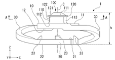
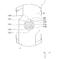
- the coupling member 1 of FIG. 1 comprises a first base 10 , a second base 20 and a third base 30 .
- the first base portion 10 and the second base portion 20 are separated from each other, and the first base portion 10 and the second base portion 20 are connected by the third base portion 30 .
- the vertical direction of the coupling member 1 is parallel to the Z-axis, the positive direction of the Z-axis is called upward, and the negative direction of the Z-axis is called downward.
- the Z-axis is orthogonal to the X-axis and Y-axis, and the X-axis and Y-axis are orthogonal to each other.
- the connecting member 1 has a first base portion 10 side, a shaft portion 110 , and an enlarged diameter portion 120 provided at one end (end portion 111 ) of the shaft portion 110 in the vertical direction.
- a unit 100 is provided.
- FIG. 2 shows a perspective view of the coupling member 1 viewed from the second base portion 20 side of the coupling member 1 .
- the coupling member 1 includes a second portion 200 extending in the radial direction of the shaft portion 110 on the second base portion 20 side.
- the first portion 100 is provided on the side of the first base portion 10, which is one end portion of the coupling member 1 in the vertical direction
- the second portion 100 is provided on the side of the second base portion 20, which is the other end portion of the coupling member 1 in the vertical direction.
- 200 are provided.
- the first base portion 10 has a first upper surface 11 and a first lower surface 12 in the vertical direction of the coupling member 1
- the second base portion 20 has a second upper surface 21 and a second lower surface 22 in the vertical direction of the coupling member 1 .
- a protrusion 23 may be provided on the second upper surface 21 of the second base 20 .
- the first portion 100 has a shaft portion 110 and an enlarged diameter portion 120 provided at one end (end portion 111 ) of the shaft portion 110 in the vertical direction.
- the shaft portion 110 is connected to the enlarged diameter portion 120 at the end portion 111 and connected to the first upper surface 11 of the first base portion 10 at the end portion 112 opposite to the end portion 111 .
- the vertical direction of the coupling member 1 and the axis c of the shaft portion 110 are parallel.
- the axis c of the shaft portion 110 is a line passing through the center of the shaft portion 110 and parallel to the direction in which the shaft portion 110 extends.
- FIG. 3 is a schematic side view of the coupling member 1 of FIG. 1 viewed in a direction (Y-axis direction) perpendicular to the vertical direction of the coupling member 1.
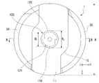
- FIG. 4 is a schematic top view of the coupling member 1 of FIG. 1 as seen from the first base 10 side in a direction parallel to the vertical direction of the coupling member 1 (the negative direction of the Z-axis).
- the enlarged diameter portion 120 has a surface 121 and a surface 122, and is connected to the end portion 111 of the shaft portion 110 on the surface 122 side.
- the height along the axis c of the expanded diameter portion 120 is not particularly limited, it is preferably 0.3 mm or more from the viewpoint of suppressing damage or deformation during fitting work or maintaining a good fitted state. more preferred.
- the diameter R2 of the enlarged diameter portion 120 is larger than the diameter R1 of the shaft portion 110.
- the diameter R1 of the shaft portion 110 and the diameter R2 of the enlarged diameter portion 120 refer to the outer shape of each portion when each portion is viewed in cross section on a plane orthogonal to the axis c of the shaft portion 110, as shown in FIG. diameter.
- a concave portion, a convex portion, or a notch is formed in a part of the outer shape of the shaft portion 110 or the enlarged diameter portion 120 in this cross-sectional view, a virtual circle is assumed without these portions. and the diameter thereof is defined as the diameter R1 of the shaft portion 110 or the diameter R2 of the enlarged diameter portion 120. As shown in FIG.
- the length of the longest line segment connecting the outer shape of the polygon is the diameter R1 or the diameter R2. do.
- the diameter R1 of the shaft portion 110 is not particularly limited, but is preferably 0.5 mm or more in view of the processing method and strength when the diameter is reduced.
- the diameter R2 of the expanded diameter portion 120 is not particularly limited, but is preferably larger than the diameter R1 by 0.4 mm or more for the reason of compensating for the function of engaging with the second portion 200 and not falling off.
- a surface 121 of the enlarged diameter portion 120 opposite to the surface 122 connected to the shaft portion 110 is inclined radially outward of the shaft portion 110 .
- FIG. 5 is a cross-sectional view of the shaft portion 110 on a plane perpendicular to the axis c.
- FIG. 5 is also a cross-sectional view along a plane (a plane parallel to the X-axis and the Y-axis) passing through line AA of FIG.
- the shaft portion 110 has recesses 113 (113a, 113b) that are recessed radially inward of the shaft portion 110 .
- the concave portion 113 may have substantially the same shape on any plane perpendicular to the axis c of the shaft portion 110 .
- the recess 113 is a groove extending in the direction along the axis c and having a predetermined width and depth.
- the shape of the recess 113 is not particularly limited, it may be composed of a surface 113A and a surface 113B, as shown in FIG. 5, for example.
- the surfaces 113A and 113B are adjacent to each other and extend in the direction along the axis c.
- a surface More preferably, the angle formed by 113A and surface 113B is 90° or less.
- the surface 113A and the surface 113B may be connected via a flat surface or a curved surface.
- the recess 113 may be composed of three or more planes or curved surfaces extending in the direction along the axis c. The above angle can be specified on the CAD data at the time of design.
- the surface of the shaft portion 110 excluding the concave portion 113 is preferably curved.
- the outer shape of the shaft portion 110 excluding the concave portion 113 may form an arc on a plane perpendicular to the axis c.
- the outer shape of the shaft portion 110 in a cross-sectional view of the shaft portion 110, is composed of two concave portions 113 (113a, 113b) and two first curved surface portions 114 (114a, 114b).
- the width of the recess 113 is the length of a line segment w (not shown) that connects the ends of the recess 113 (the boundary between the recess 113 and the first curved surface portion 114) in a plane orthogonal to the axis c, More preferably, the width w of 113 is 0.3 mm or more. Further, when the longest distance among the distances between the line segment w and the outer shape of the recess 113 in the direction orthogonal to the line segment w in the plane orthogonal to the axis c is defined as the depth d of the recess 113, the recess 113 is more preferably 0.3 mm or more.
- the recessed portion 113 may be provided over the entire length of the shaft portion 110 in the direction along the axis c of the shaft portion 110 or may be provided in a part of the shaft portion 110 .
- FIG. 6 shows a modified example of the concave portion 113.
- the concave portion 113 may have a cross-sectional shape that draws a curve in a plane perpendicular to the axis c.
- the concave portion 113 has a curved surface 115 that is recessed radially inward of the shaft portion 110 .
- the concave portion 113 is a curved surface, the relative rotation of the first portion 100 and the second portion 200 in the circumferential direction of the shaft portion 110 is suppressed, but by applying a constant force, it is possible to rotate in this direction. be able to.
- the number of recesses 113 may be one. Since the number of recesses 113 is small, there is an advantage that the weight of the coupling member 1 is reduced.
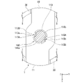
- FIG. 7 shows an example in which three recesses 113 are provided.
- the recesses 113 (113c, 113d, 113e) are provided at intervals of 120° in the circumferential direction of the shaft portion 110, and the first curved surface portions 114 (114c, 114d, 114e) are provided between the recesses 113. It is
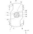
- FIG. 8 shows an example in which four recesses 113 are provided.
- the recessed portions 113 (113f, 113g, 113h, 113i) are provided at intervals of 90° in the circumferential direction of the shaft portion 110, and the first curved surface portions 114 (114f, 114g, 114h, 114i) are provided.
- the height of the shaft portion 110 along the axis c is not particularly limited, it is preferably 0.3 mm or more in order to compensate for the function of engaging with the second portion 200 and not falling off.
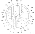
- FIG. 9 is a schematic bottom view of the coupling member 1 viewed from the second base 20 side in a direction parallel to the vertical direction of the coupling member 1 (the positive direction of the Z axis).
- a second part 200 as shown in FIG. 9 is provided on the second base part 20 side.
- the second portion 200 extends radially of the shaft portion 110 .
- the second portion 200 has convex portions 210 ( 210 a, 210 b ) corresponding to the concave portions 113 .
- the outer shape of the convex portion 210 on the plane perpendicular to the axis c of the shaft portion 110 is It preferably corresponds to the outer shape of the recess 113 .
- the convex part 210 is composed of a surface 210A and a surface 210B.
- the second portion 200 also has a connection surface 201 on the side of the second bottom surface 22 of the second base portion 20 .
- the connecting surface 201 faces the first upper surface 11 of the first base portion 10 when the connecting members 1 are connected to each other.
- the outer shape of the convex portion 210 on the plane orthogonal to the axis c of the shaft portion 110 does not have to be exactly the same as the outer shape of the concave portion 113. It is sufficient that it corresponds to the outer shape of the concave portion 113 within a range in which the relative rotation with the .
- the second portion 200 may include second curved surface portions 220 (220a, 220b) corresponding to the first curved surface portion 114 of the shaft portion 110 and adjacent to the convex portion 210.
- the second curved surface portion 220 curves and extends along the direction in which the second portion 200 extends.
- the second curved surface portion 220 preferably has a surface shape corresponding to that of the first curved surface portion 114 .
- the shape of the second curved surface portion 220 may be an arc.
- the diameter R3 of an imaginary circle ra whose circumference is part of the arc be the same as the diameter R1 of the shaft portion 110 .
- the diameter R3 of the circle ra is smaller than the diameter R2 of the enlarged diameter portion 120 .
- the second part 200a has arms 230 (230a, 230b), the arms 230 connect the convex part 210a and the second curved surface part 220a to the second base part 20, and the second part 200b Arm portions 230 ( 230 c and 230 d ) are provided, and the arm portions 230 connect the convex portion 210 b and the second curved surface portion 220 b to the second base portion 20 .
- the diameter R4 of the circle rb is smaller than the diameter R3 of the circle ra.
- the second portion 200 is elastically deformable at least in the radial direction of the shaft portion 110 .
- the second part 200 (200a, 200b) is elastically deformed to expand the diameter R4 of the circle rb.
- the diameter R4 of the circle rb becomes larger than the diameter R2 of the expanded diameter portion 120, and the first portion 100 can be fitted to the second portion 200.
- FIG. As a result, it is possible to soften the feel when connecting the connecting members 1 to each other, and to ensure the connection between the connecting members 1 after fitting.
- FIG. 10 is a diagram for explaining a modification of the protrusion 210, in which the coupling member 1 is viewed from the second base 20 side in a direction parallel to the vertical direction of the coupling member 1 (the positive direction of the Z axis).
- 1 is a schematic bottom view;
- the convex portion 210 in FIG. 10 has a curved cross-sectional shape corresponding to the concave portion 113 illustrated in FIG. 6 on a plane perpendicular to the axis c.
- protrusions 210 there may be two protrusions 210, but the number of protrusions 210 may be one. Since the number of protrusions 210 is small, it is possible to reduce the cross-sectional area of the path of heat transmitted through the joint member 1 when the joint member 1 is used as a heat insulating structure, for example.
- three, four, or five or more second parts 200 may be provided in consideration of the strength and elasticity of the material of the coupling member 1 . This increases the stability of connection between the coupling members 1 .
- FIG. 11 shows an example in which three second parts 200 (200c, 200d, 200e) are provided.
- three protrusions 210 are provided, and the protrusions 210 (210c, 210d, 210e) are provided at intervals of 120° in the circumferential direction of a virtual circle rb inscribed in the protrusions 210.
- the second part 200 shown in FIG. 11 corresponds to the first part 100 provided with three recesses 113 (113c, 113d, 113e) illustrated in FIG.
- FIG. 12 shows an example in which four second parts 200 (200f, 200g, 200h, 200i) are provided.
- four convex portions 210 are provided, and the convex portions 210 (210f, 210g, 210h, 210i) are provided at intervals of 90° in the circumferential direction of a virtual circle rb inscribed in the convex portion 210.
- the second part 200 shown in FIG. 12 corresponds to the first part 100 provided with four recesses 113 (113f, 113g, 113h, 113i) illustrated in FIG.
- the second part 200 shown in FIG. 11 or 12 is connected to the second base part 20 at one end in the longitudinal direction. It is elastically deformable at least in the radial direction of the shaft portion 110 when pressure is applied. As a result, it is possible to soften the feel when connecting the connecting members 1 to each other, and to ensure the connection between the connecting members 1 after fitting.
- the coupling member 1 according to this embodiment is preferably made of a resin material as described later. Since the connecting member 1 is made of a resin material, the second portion 200 can be given a suitable elastic deformability, and the connecting members 1 can be connected without using a special tool. The fitting state between the first part 100 and the second part 200 can be maintained satisfactorily.
- the height of the coupling member 1 of the second part 200 along the vertical direction is not particularly limited, but is preferably 0.6 mm or more for the reason of compensating for the function of engaging with the second part 200 and not falling off. Since the second part 200 has no structure in the vertical direction of the connecting member 1, it can be formed thin, and the weight of the connecting member 1 can be reduced. The height, width, depth, etc. of each member described above are measured using a measuring instrument such as a micrometer.
- the third base 30 is connected to the first base 10 and the other end of the third base 30 is connected to the second base 20 .
- the length of the third base 30 may be longer than the distance between the first base 10 and the second base 20 .
- the third base 30 is paired and helically shaped. By adopting such a shape, the stability of the connecting member 1 is ensured, and the connecting member 1 can be elastically deformed smoothly in the vertical direction. Further, the coupling member 1 may be elastically deformable in the vertical direction of the coupling member 1 by elastically deforming the third base portion 30 .
- the height h of the connecting member 1 in the vertical direction is 1.2 mm or more from the viewpoint of functioning as a structure that maintains the distance between the heat insulating film layers in the MLI and ensuring the function of good connection between the connecting members 1. is preferred.
- the outer diameter R of the connecting member 1 on a plane orthogonal to the vertical direction is preferably 5 mm or more from the viewpoint of preventing buckling due to a vertical load when the connecting member 1 is connected in the vertical direction.
- the height of the connecting member is the distance along the vertical direction of the connecting member 1 from the first upper surface 11 of the first base portion 10 to the second lower surface 22 of the second base portion 20 .
- the outer diameter of the connecting member 1 is the outer shape of the third base portion 30 .
- the connecting member 1 is preferably made of a resin material such as polyetheretherketone (PEEK), polycarbonate (PC), polyethylene terephthalate (PET), polyimide (PI), or the like.
- the coupling member 1 is manufactured by injection molding raw materials of these resin materials.
- the configuration of the coupling member 1 is not limited to this, and may be made of any other suitable material.
- Polyetheretherketone is the most preferable material for the connecting member 1 from the viewpoint of high heat resistance, low-temperature embrittlement resistance, low outgassing in a vacuum, and ultraviolet resistance, which are required as a heat insulating material for space transport. .
- the connecting member 1 according to the above embodiment has a simple structure and is therefore lightweight. Moreover, the connection between the connecting members 1 is strong.
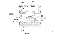
- 13 to 15 show portions near the axes c1 and c2, and some portions of the coupling member 1001 and the coupling member 2001 are omitted. 13 to 15 correspond to cross-sectional views taken along a plane (parallel to the X-axis and Z-axis) passing through line BB in FIG. 4 and line CC in FIG.
- the coupling member 1001 and the coupling member 2001 are relatively moved along the vertical direction in a direction in which the coupling member 1001 and the coupling member 2001 approach each other, and as shown in FIG.
- the surface 1121 of the portion 1120 and the second portion 2200 of the coupling member 2001 are brought into contact.
- the second portion 2200 of the coupling member 2001 is elastically deformable, the second portion of the coupling member 2001 can be deformed by relatively moving the coupling member 1001 and the coupling member 2001 in a direction in which the coupling members 1001 and 2001 approach each other. 2200 deforms according to the shape of the enlarged diameter portion 1120 of the coupling member 1001 . Specifically, the second portion 2200 of the coupling member 2001 deforms at least radially outward of the shaft portion 1110 .
- FIGS. 13-15 The actual operation in FIGS. 13-15 is to push one coupling member against the other, where the second portion 2200 of coupling member 2001 is the first portion of coupling member 1001. 1100 not only expands in the direction away from the enlarged diameter portion 1120, but also inclines along the inclined shape of the surface 1121 while contacting the circumference of the enlarged diameter portion 1120, so that the pressing force required for connecting the coupling members is reduced. .
- 13 to 15 show an example in which the axis c1 of the coupling member 1001 and the axis c2 of the coupling member 2001 are aligned and connected.
- the second portion 2200 of the coupling member 2001 is in contact with the circumference of the enlarged diameter portion 1120 and is inclined along the inclined shape of the surface 1121, even if the axes of the coupling members are not aligned with each other, it is possible to fit.
- the misalignment of the fitting projection with respect to the mating hole in the direction of the insertion axis is suppressed, and the two coupling members can be easily connected.
- the state shown in FIG. 15 is obtained by relatively moving the coupling member 1001 and the coupling member 2001 in the direction in which the coupling member 1001 and the coupling member 2001 approach each other.
- the second portion 2200 of the coupling member 2001 sandwiches the shaft portion 1110 of the coupling member 1001 from the radially outer side of the shaft portion 1110 of the coupling member 1001 .
- a portion of the surface 1122 of the enlarged diameter portion 1120 of the coupling member 1001 faces a portion of the connection surface of the second portion 2200 of the coupling member 2001 .
- this state is called a semi-fitted state.
- this state can be regarded as a fitted state.
- the first portion 1100 of the coupling member 1001 and the second portion 2200 of the coupling member 2001 are fitted, and in a state where the coupling member 1001 and the coupling member 2001 are connected, the axis c of the coupling member 1001 1 (the axis c 2 of the coupling member 2001) relative positions of the coupling member 1001 and the coupling member 2001 in the circumferential direction are fixed. Also, in this state, relative rotation between the coupling member 1001 and the coupling member 2001 in the circumferential direction of the axis c 1 of the coupling member 1001 (the axis c 2 of the coupling member 2001) is suppressed.
- the parts in a mating structure consisting of a protrusion and a hole, if a rotation stop mechanism is provided, the parts must be in a state in which they are oriented to each other in order to prevent rotation during fitting work.
- the insertion operation for mating cannot be performed.
- connection between the connecting members 1 is not easily released.
- it is not easy to release the connection by a simple action such as pulling the connecting member 1 in the connected state in the vertical direction, or inserting a thin object such as a flat-blade screwdriver into the gap between the two connecting members 1 and prying. do not have.
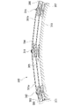
- one embodiment of the present invention is a heat insulating structure including a heat insulating film and a plurality of connecting members supporting the heat insulating film, wherein the heat insulating structure uses the connecting member according to the above embodiment as the connecting member. be.
- the vertical direction of the connecting member intersects with the surface of the heat insulating film.
- FIG. 16 is a schematic cross-sectional view of the heat insulating structure 300 according to the present embodiment, viewed in a direction parallel to the surfaces of the heat insulating films 301 (301a, 301b) constituting the heat insulating structure 300 according to the present embodiment. be.
- the connecting members 302 and 303, the connecting members 304 and 305, and the connecting members 306 and 307 are connected to each other, and the vertical direction thereof intersects the surface of the insulating film 301.
- the heat insulating structure 300 is provided on the surface 311 of the substrate 310 via the connecting members 302-307.
- the connecting members 302 to 307 are connected in the direction in which the heat insulation film 301 is laminated, as shown in FIG.
- One or more heat insulating films 301 may be sandwiched between the two connecting members to be connected.
- the heat insulating film 301 is a low emissivity film capable of suppressing heat transfer by radiation.
- the heat-insulating film 301 is not particularly limited, but is made by vapor-depositing a metal such as aluminum, gold, germanium, or conductive indium tin oxide (ITO) on a resin film such as polyimide or polyester.
- ITO conductive indium tin oxide
- the fitting structure according to the present invention is described by taking the coupling member as an example, but the fitting structure according to the present invention is not limited to this example.
- the first part and the second part of the mating structure are provided on a single part, but the first part and the second part of the mating structure are provided on separate parts. may have been Moreover, even when the first part and the second part of the fitting structure are provided in a single part, for example, the first part and the second part may exist on the same plane.
- the coupling member of the embodiment described above an example in which the axis of the shaft portion of the first portion and the connection surface of the second portion are substantially perpendicular to each other is shown. may have an angle to each other, or may be in a parallel positional relationship.
- one component may be provided with a plurality of first parts or a plurality of second parts.
- the connecting member according to the present invention When the connecting member according to the present invention is used in a heat insulating structure, the mass of the heat insulating structure can be reduced.
- the fitting structure or coupling member according to the present invention may be used as a fitting structure or coupling member for fixing security measure members such as shoplifting/theft prevention sensors and buzzers.
- the fitting structure or connecting member according to the present invention includes sealing rings such as returnable boxes and cash transport bags, sealing tools such as sealing bands, and devices/toys that prevent dismantling/improvement assembly without using adhesives or screws. can be used for
Abstract
Description
軸部と、前記軸部の一端に設けられた拡径部とを有する第一部と、
前記軸部の径方向の外側から前記第一部を挟み込む第二部と、を備え、
前記拡径部の直径が前記軸部の直径よりも大きく、
前記軸部が前記軸部の径方向の内側へ向けてへこむ凹部を有し、
前記第二部が、前記軸部の径方向に延在しかつ、少なくとも前記軸部の径方向において弾性変形可能であり、
前記第二部が、前記凹部と対応する凸部を有しかつ、前記凹部に前記凸部が係合する
ことを特徴とする。
(2)上記(1)に記載の嵌合構造では、
前記軸部が第一曲面部を有し、
前記第二部が、前記第一曲面部と対応しかつ前記凸部に隣接する第二曲面部を備えていてもよい。
(3)上記(1)又は(2)に記載の嵌合構造では、
前記拡径部の前記軸部と接続される側の面とは反対側の面が前記軸部の前記径方向の外側へ向けて傾斜していてもよい。
(4)上記(1)から(3)のいずれか1項に記載の嵌合構造では、
前記凹部に対して前記凸部が係合された状態で、前記軸部の軸線と直交する面において、前記第一部に対して前記第二部が相対的に回転しないように保持されてもよい。 (1) A fitting structure according to one aspect of the present invention includes:
a first portion having a shaft portion and an enlarged diameter portion provided at one end of the shaft portion;
a second portion that sandwiches the first portion from the radially outer side of the shaft portion;
the diameter of the enlarged diameter portion is larger than the diameter of the shaft portion;
The shaft portion has a concave portion that is recessed radially inward of the shaft portion,
the second portion extends in the radial direction of the shaft portion and is elastically deformable at least in the radial direction of the shaft portion;
The second part has a protrusion corresponding to the recess, and the protrusion is engaged with the recess.
(2) In the fitting structure described in (1) above,
the shaft portion has a first curved surface portion,
The second portion may have a second curved portion corresponding to the first curved portion and adjacent to the convex portion.
(3) In the fitting structure described in (1) or (2) above,
A surface of the enlarged diameter portion opposite to the surface connected to the shaft portion may be inclined outward in the radial direction of the shaft portion.
(4) In the fitting structure according to any one of (1) to (3) above,
Even if the second portion is held so as not to rotate relative to the first portion on a plane perpendicular to the axis of the shaft portion in a state where the convex portion is engaged with the concave portion. good.
互いに接続される結合部材であって、
前記結合部材の上下方向の一方の端部側に設けられ、前記上下方向と平行な軸線を有する軸部と、前記軸部の一端に設けられた拡径部とを有する第一部と、
前記結合部材の上下方向の他方の端部側に設けられた第二部と、を備え、
前記拡径部の直径が前記軸部の直径よりも大きく、
前記軸部が前記軸部の径方向の内側へ向けてへこむ凹部を有し、
前記第二部が、前記軸部の径方向に延在しかつ、少なくとも前記前記軸部の径方向において弾性変形可能であり、
前記第二部が、前記凹部と対応する凸部を有しかつ、前記凹部に対して前記凸部が係合することで前記部材同士を接続可能である
ことを特徴とする。
(6)上記(5)に記載の結合部材では、
前記軸部が第一曲面部を有し、
前記第二部が、前記第一曲面部と対応しかつ前記凸部に隣接する第二曲面部を備えていてもよい。
(7)上記(5)又は(6)に記載の結合部材では、
前記拡径部の前記軸部と接続される側の面とは反対側の面が前記軸部の前記径方向の外側へ向けて傾斜していてもよい。
(8)上記(5)から(7)のいずれか1項に記載の結合部材では、
前記凹部に対して前記凸部が係合された状態で、前記軸部の軸線と直交する面において、前記第一部に対して前記第二部が相対的に回転しないように保持されてもよい。 (5) A connecting member according to one aspect of the present invention,
Coupling members connected to each other,
a first portion provided on one end side of the coupling member in the vertical direction and having a shaft portion having an axis parallel to the vertical direction; and an enlarged diameter portion provided at one end of the shaft portion;
a second part provided on the other end side in the vertical direction of the coupling member,
the diameter of the enlarged diameter portion is larger than the diameter of the shaft portion;
The shaft portion has a concave portion that is recessed radially inward of the shaft portion,
the second portion extends in the radial direction of the shaft portion and is elastically deformable at least in the radial direction of the shaft portion;
The second part has a protrusion corresponding to the recess, and the members can be connected by engaging the protrusion with the recess.
(6) In the coupling member described in (5) above,
the shaft portion has a first curved surface portion,
The second portion may have a second curved portion corresponding to the first curved portion and adjacent to the convex portion.
(7) In the connecting member according to (5) or (6) above,
A surface of the enlarged diameter portion opposite to the surface connected to the shaft portion may be inclined outward in the radial direction of the shaft portion.
(8) In the connecting member according to any one of (5) to (7) above,
Even if the second portion is held so as not to rotate relative to the first portion on a plane perpendicular to the axis of the shaft portion in a state where the convex portion is engaged with the concave portion. good.
以下、本発明に係る嵌合構造について、図1に示す結合部材1を例に挙げて説明する。図1の結合部材1は、第一基部10、第二基部20、および第三基部30を備える。結合部材1の上下方向において、第一基部10と第二基部20とは互いに離間し、第一基部10と第二基部20とを第三基部30が接続する。以下、結合部材1の上下方向は、Z軸と平行な方向とし、Z軸の正方向を上方向、Z軸の負方向を下方向と称する。Z軸はX軸およびY軸と直交し、X軸とY軸は互いに直交する。 [Coupling member]
Hereinafter, the fitting structure according to the present invention will be described by taking the
第一部100は、軸部110と、軸部110の上下方向の一端(端部111)に設けられた拡径部120とを有する。軸部110は端部111において拡径部120と接続され、端部111とは反対側の端部112において第一基部10の第一上面11と接続される。図1の例では、結合部材1の上下方向と軸部110の軸線cとは平行である。軸部110の軸線cは、軸部110の中心を通りかつ軸部110が延在する方向と平行な線である。 (Part One)
The
図9は、結合部材1の上下方向に平行な方向(Z軸の正方向)において、結合部材1を第二基部20側から見た概略的な下面図である。第二基部20側には、図9に示すような、第二部200を備える。図9の例では、2つの第二部200(200a、200b)が存在する。 (Part 2)
FIG. 9 is a schematic bottom view of the
次に、上述した結合部材1同士を互いに接続する形態を説明する。2つの結合部材1を接続する場合には、一方の結合部材1の第一部100と他方の結合部材1の第二部200とを互いに嵌合させる。図13~図15に、2つの結合部材を接続する際の、結合部材の概略的な断面図を示す。図13~図15には、結合部材1001の軸部1110の軸線c1と結合部材2001の軸部(図示せず)の軸線c2が一致し、これらの軸線を通る平面における結合部材1001および結合部材2001の断面を示している。図13~図15には、軸線c1および軸線c2近傍の部位を示しており、結合部材1001および結合部材2001の部位のうちで図示を省略しているものもある。図13~図15は、図4のB-B線および図9のC-C線を通る平面(X軸およびZ軸と平行な平面)における断面図と対応する。 [Connection of connecting members]
Next, a mode for connecting the above-described connecting
10 第一基部
20 第二基部
30 第三基部
100 第一部
110 軸部
113 凹部
120 拡径部
200 第二部
210 凸部 1 Joining
Claims (8)
- 軸部と、前記軸部の一端に設けられた拡径部とを有する第一部と、
前記軸部の径方向の外側から前記第一部を挟み込む第二部と、を備え、
前記拡径部の直径が前記軸部の直径よりも大きく、
前記軸部が前記軸部の径方向の内側へ向けてへこむ凹部を有し、
前記第二部が、前記軸部の径方向に延在しかつ、少なくとも前記軸部の径方向において弾性変形可能であり、
前記第二部が、前記凹部と対応する凸部を有しかつ、前記凹部に前記凸部が係合する
ことを特徴とする嵌合構造。 a first portion having a shaft portion and an enlarged diameter portion provided at one end of the shaft portion;
a second portion that sandwiches the first portion from the radially outer side of the shaft portion;
the diameter of the enlarged diameter portion is larger than the diameter of the shaft portion;
The shaft portion has a concave portion that is recessed radially inward of the shaft portion,
the second portion extends in the radial direction of the shaft portion and is elastically deformable at least in the radial direction of the shaft portion;
The fitting structure, wherein the second part has a protrusion corresponding to the recess, and the protrusion engages with the recess. - 前記軸部が第一曲面部を有し、
前記第二部が、前記第一曲面部と対応しかつ前記凸部に隣接する第二曲面部を備える、
ことを特徴とする請求項1に記載の嵌合構造。 the shaft portion has a first curved surface portion,
wherein the second portion comprises a second curved portion corresponding to the first curved portion and adjacent to the convex portion;
The fitting structure according to claim 1, characterized in that: - 前記拡径部の前記軸部と接続される側の面とは反対側の面が前記軸部の前記径方向の外側へ向けて傾斜している
ことを特徴とする請求項1又は2に記載の嵌合構造。 3. A surface according to claim 1, wherein a surface of the enlarged diameter portion opposite to a surface connected to the shaft portion is inclined outward in the radial direction of the shaft portion. mating structure. - 前記凹部に対して前記凸部が係合された状態で、前記軸部の軸線と直交する面において、前記第一部に対して前記第二部が相対的に回転しないように保持される
ことを特徴とする請求項1から3のいずれか1項に記載の嵌合構造。 In a state in which the convex portion is engaged with the concave portion, the second portion is held so as not to rotate relative to the first portion on a plane perpendicular to the axis of the shaft portion. The fitting structure according to any one of claims 1 to 3, characterized by: - 互いに接続される結合部材であって、
前記結合部材の上下方向の一方の端部側に設けられ、前記上下方向と平行な軸線を有する軸部と、前記軸部の一端に設けられた拡径部とを有する第一部と、
前記結合部材の上下方向の他方の端部側に設けられた第二部と、を備え、
前記拡径部の直径が前記軸部の直径よりも大きく、
前記軸部が前記軸部の径方向の内側へ向けてへこむ凹部を有し、
前記第二部が、前記軸部の径方向に延在しかつ、少なくとも前記前記軸部の径方向において弾性変形可能であり、
前記第二部が、前記凹部と対応する凸部を有しかつ、前記凹部に対して前記凸部が係合することで前記部材同士を接続可能である
ことを特徴とする結合部材。 Coupling members connected to each other,
a first portion provided on one end side of the coupling member in the vertical direction and having a shaft portion having an axis parallel to the vertical direction; and an enlarged diameter portion provided at one end of the shaft portion;
a second part provided on the other end side in the vertical direction of the coupling member,
the diameter of the enlarged diameter portion is larger than the diameter of the shaft portion;
The shaft portion has a concave portion that is recessed radially inward of the shaft portion,
the second portion extends in the radial direction of the shaft portion and is elastically deformable at least in the radial direction of the shaft portion;
A connecting member, wherein the second part has a protrusion corresponding to the recess, and the members can be connected by engaging the protrusion with the recess. - 前記軸部が第一曲面部を有し、
前記第二部が、前記第一曲面部と対応しかつ前記凸部に隣接する第二曲面部を備える、
ことを特徴とする請求項5に記載の結合部材。 the shaft portion has a first curved surface portion,
wherein the second portion comprises a second curved portion corresponding to the first curved portion and adjacent to the convex portion;
6. A coupling member according to claim 5, characterized in that: - 前記拡径部の前記軸部と接続される側の面とは反対側の面が前記軸部の前記径方向の外側へ向けて傾斜している
ことを特徴とする請求項5又は6に記載の結合部材。 7. A surface according to claim 5 or 6, wherein a surface of the enlarged diameter portion opposite to a surface connected to the shaft portion is inclined outward in the radial direction of the shaft portion. connecting member. - 前記凹部に対して前記凸部が係合された状態で、前記軸部の軸線と直交する面において、前記第一部に対して前記第二部が相対的に回転しないように保持される
ことを特徴とする請求項5から7のいずれか1項に記載の結合部材。 In a state in which the convex portion is engaged with the concave portion, the second portion is held so as not to rotate relative to the first portion on a plane perpendicular to the axis of the shaft portion. A coupling member according to any one of claims 5 to 7, characterized in that:
Priority Applications (3)
| Application Number | Priority Date | Filing Date | Title |
|---|---|---|---|
| JP2023517004A JPWO2022230176A1 (en) | 2021-04-30 | 2021-04-30 | |
| PCT/JP2021/017211 WO2022230176A1 (en) | 2021-04-30 | 2021-04-30 | Engagement structure and coupling member |
| EP21939334.5A EP4332392A1 (en) | 2021-04-30 | 2021-04-30 | Engagement structure and coupling member |
Applications Claiming Priority (1)
| Application Number | Priority Date | Filing Date | Title |
|---|---|---|---|
| PCT/JP2021/017211 WO2022230176A1 (en) | 2021-04-30 | 2021-04-30 | Engagement structure and coupling member |
Publications (1)
| Publication Number | Publication Date |
|---|---|
| WO2022230176A1 true WO2022230176A1 (en) | 2022-11-03 |
Family
ID=83848198
Family Applications (1)
| Application Number | Title | Priority Date | Filing Date |
|---|---|---|---|
| PCT/JP2021/017211 WO2022230176A1 (en) | 2021-04-30 | 2021-04-30 | Engagement structure and coupling member |
Country Status (3)
| Country | Link |
|---|---|
| EP (1) | EP4332392A1 (en) |
| JP (1) | JPWO2022230176A1 (en) |
| WO (1) | WO2022230176A1 (en) |
Citations (7)
| Publication number | Priority date | Publication date | Assignee | Title |
|---|---|---|---|---|
| US1412970A (en) * | 1921-10-20 | 1922-04-18 | Leroy L Salfisberg | Attaching device |
| JP3005526U (en) * | 1994-06-23 | 1995-01-10 | 睦 里見 | Fixture and fixing structure |
| WO2011049096A1 (en) * | 2009-10-20 | 2011-04-28 | 株式会社ニフコ | Clip |
| US8234835B2 (en) | 2007-03-16 | 2012-08-07 | Quest Product Development Corporation | Integrated multilayer insulation |
| US20170057391A1 (en) * | 2015-07-29 | 2017-03-02 | Macneil Ip Llc | Multi-vehicle retention grommet |
| US20170073090A1 (en) | 2015-09-16 | 2017-03-16 | U.S.A. As Represented By The Administrator Of The National Aeronautics And Space Administration | Cryogenic hydrogen radiation shield for human spaceflight |
| JP2017075663A (en) * | 2015-10-16 | 2017-04-20 | ナックス株式会社 | Fastener |
-
2021
- 2021-04-30 JP JP2023517004A patent/JPWO2022230176A1/ja active Pending
- 2021-04-30 EP EP21939334.5A patent/EP4332392A1/en active Pending
- 2021-04-30 WO PCT/JP2021/017211 patent/WO2022230176A1/en active Application Filing
Patent Citations (7)
| Publication number | Priority date | Publication date | Assignee | Title |
|---|---|---|---|---|
| US1412970A (en) * | 1921-10-20 | 1922-04-18 | Leroy L Salfisberg | Attaching device |
| JP3005526U (en) * | 1994-06-23 | 1995-01-10 | 睦 里見 | Fixture and fixing structure |
| US8234835B2 (en) | 2007-03-16 | 2012-08-07 | Quest Product Development Corporation | Integrated multilayer insulation |
| WO2011049096A1 (en) * | 2009-10-20 | 2011-04-28 | 株式会社ニフコ | Clip |
| US20170057391A1 (en) * | 2015-07-29 | 2017-03-02 | Macneil Ip Llc | Multi-vehicle retention grommet |
| US20170073090A1 (en) | 2015-09-16 | 2017-03-16 | U.S.A. As Represented By The Administrator Of The National Aeronautics And Space Administration | Cryogenic hydrogen radiation shield for human spaceflight |
| JP2017075663A (en) * | 2015-10-16 | 2017-04-20 | ナックス株式会社 | Fastener |
Also Published As
| Publication number | Publication date |
|---|---|
| EP4332392A1 (en) | 2024-03-06 |
| JPWO2022230176A1 (en) | 2022-11-03 |
Similar Documents
| Publication | Publication Date | Title |
|---|---|---|
| US11812635B2 (en) | Protection film having base layer over adhesive layer | |
| US10578718B1 (en) | Rotatable mirror assemblies | |
| TWI376775B (en) | Dynamic kinematic mount | |
| JP6359636B2 (en) | Sealed insulation tank | |
| US20140007376A1 (en) | Flexible composite hinge | |
| EP2412624A1 (en) | Cargo tank for liquefied gas carrier ship | |
| WO2022230176A1 (en) | Engagement structure and coupling member | |
| US9366071B1 (en) | Low-friction spacer system for vacuum insulated glass | |
| US20190353250A1 (en) | Composite Seal Member | |
| IL221990A (en) | Multi-stage flexural pivot | |
| JP2003294153A (en) | Plate brush sealing device | |
| KR20150028555A (en) | Cargo for liquefied gas carrier ship | |
| WO2018052143A1 (en) | Linear extension/retraction mechanism and robot arm mechanism | |
| JP6986259B2 (en) | Multi-layer insulation material and insulation method using it | |
| JP2007155279A (en) | Heat insulated case body | |
| US11116342B1 (en) | Pocket straw | |
| JP4232153B2 (en) | Multilayer glass resonance member holding structure and resonance member | |
| US20230092107A1 (en) | Wire/Ring Secondary Retention System For Optical And Other Members | |
| EP2760753A1 (en) | Surface element for friction increase as well as objects provided with said surface element | |
| US11974452B2 (en) | Protection film and electronic device including the same | |
| US20230029476A1 (en) | Rotating assembly, handle locking devices, and chassis | |
| WO2022145467A1 (en) | Sealing member, sealing mechanism, valve, and sealing method | |
| KR102654227B1 (en) | coupling using carbon fiber | |
| JP7461203B2 (en) | Adhesive container | |
| US20230341090A1 (en) | Fluid storage container |
Legal Events
| Date | Code | Title | Description |
|---|---|---|---|
| 121 | Ep: the epo has been informed by wipo that ep was designated in this application |
Ref document number: 21939334 Country of ref document: EP Kind code of ref document: A1 |
|
| WWE | Wipo information: entry into national phase |
Ref document number: 2023517004 Country of ref document: JP |
|
| WWE | Wipo information: entry into national phase |
Ref document number: 2021939334 Country of ref document: EP |
|
| ENP | Entry into the national phase |
Ref document number: 2021939334 Country of ref document: EP Effective date: 20231130 |
|
| NENP | Non-entry into the national phase |
Ref country code: DE |