WO2022224573A1 - Drive element and light deflection element - Google Patents
Drive element and light deflection element Download PDFInfo
- Publication number
- WO2022224573A1 WO2022224573A1 PCT/JP2022/006579 JP2022006579W WO2022224573A1 WO 2022224573 A1 WO2022224573 A1 WO 2022224573A1 JP 2022006579 W JP2022006579 W JP 2022006579W WO 2022224573 A1 WO2022224573 A1 WO 2022224573A1
- Authority
- WO
- WIPO (PCT)
- Prior art keywords
- driving
- pair
- portions
- drive
- movable
- Prior art date
Links
- 230000003287 optical effect Effects 0.000 claims description 8
- 238000004088 simulation Methods 0.000 description 25
- 239000000463 material Substances 0.000 description 19
- 238000006073 displacement reaction Methods 0.000 description 13
- 238000012795 verification Methods 0.000 description 6
- 230000000694 effects Effects 0.000 description 5
- 238000009434 installation Methods 0.000 description 3
- BASFCYQUMIYNBI-UHFFFAOYSA-N platinum Chemical compound [Pt] BASFCYQUMIYNBI-UHFFFAOYSA-N 0.000 description 3
- 239000010703 silicon Substances 0.000 description 3
- 229910052710 silicon Inorganic materials 0.000 description 3
- 239000000758 substrate Substances 0.000 description 3
- 239000010409 thin film Substances 0.000 description 3
- 230000007423 decrease Effects 0.000 description 2
- 229910052451 lead zirconate titanate Inorganic materials 0.000 description 2
- 229910001369 Brass Inorganic materials 0.000 description 1
- 229910000942 Elinvar Inorganic materials 0.000 description 1
- 240000007594 Oryza sativa Species 0.000 description 1
- 235000007164 Oryza sativa Nutrition 0.000 description 1
- RTAQQCXQSZGOHL-UHFFFAOYSA-N Titanium Chemical compound [Ti] RTAQQCXQSZGOHL-UHFFFAOYSA-N 0.000 description 1
- 229910045601 alloy Inorganic materials 0.000 description 1
- 239000000956 alloy Substances 0.000 description 1
- 230000003321 amplification Effects 0.000 description 1
- 238000005452 bending Methods 0.000 description 1
- 239000010951 brass Substances 0.000 description 1
- 239000013078 crystal Substances 0.000 description 1
- 230000003247 decreasing effect Effects 0.000 description 1
- 238000005516 engineering process Methods 0.000 description 1
- 239000010408 film Substances 0.000 description 1
- 239000011521 glass Substances 0.000 description 1
- HFGPZNIAWCZYJU-UHFFFAOYSA-N lead zirconate titanate Chemical compound [O-2].[O-2].[O-2].[O-2].[O-2].[Ti+4].[Zr+4].[Pb+2] HFGPZNIAWCZYJU-UHFFFAOYSA-N 0.000 description 1
- 239000002184 metal Substances 0.000 description 1
- 229910052751 metal Inorganic materials 0.000 description 1
- 150000002739 metals Chemical class 0.000 description 1
- 238000003199 nucleic acid amplification method Methods 0.000 description 1
- 229910052697 platinum Inorganic materials 0.000 description 1
- 239000011347 resin Substances 0.000 description 1
- 229920005989 resin Polymers 0.000 description 1
- 235000009566 rice Nutrition 0.000 description 1
- 238000009751 slip forming Methods 0.000 description 1
- 238000004544 sputter deposition Methods 0.000 description 1
- 239000010935 stainless steel Substances 0.000 description 1
- 229910001220 stainless steel Inorganic materials 0.000 description 1
- 239000010936 titanium Substances 0.000 description 1
- 229910052719 titanium Inorganic materials 0.000 description 1
- 238000007740 vapor deposition Methods 0.000 description 1
Images


Classifications
-
- G—PHYSICS
- G02—OPTICS
- G02B—OPTICAL ELEMENTS, SYSTEMS OR APPARATUS
- G02B26/00—Optical devices or arrangements for the control of light using movable or deformable optical elements
- G02B26/08—Optical devices or arrangements for the control of light using movable or deformable optical elements for controlling the direction of light
- G02B26/0816—Optical devices or arrangements for the control of light using movable or deformable optical elements for controlling the direction of light by means of one or more reflecting elements
-
- B—PERFORMING OPERATIONS; TRANSPORTING
- B06—GENERATING OR TRANSMITTING MECHANICAL VIBRATIONS IN GENERAL
- B06B—METHODS OR APPARATUS FOR GENERATING OR TRANSMITTING MECHANICAL VIBRATIONS OF INFRASONIC, SONIC, OR ULTRASONIC FREQUENCY, e.g. FOR PERFORMING MECHANICAL WORK IN GENERAL
- B06B1/00—Methods or apparatus for generating mechanical vibrations of infrasonic, sonic, or ultrasonic frequency
- B06B1/02—Methods or apparatus for generating mechanical vibrations of infrasonic, sonic, or ultrasonic frequency making use of electrical energy
- B06B1/06—Methods or apparatus for generating mechanical vibrations of infrasonic, sonic, or ultrasonic frequency making use of electrical energy operating with piezoelectric effect or with electrostriction
-
- B—PERFORMING OPERATIONS; TRANSPORTING
- B81—MICROSTRUCTURAL TECHNOLOGY
- B81B—MICROSTRUCTURAL DEVICES OR SYSTEMS, e.g. MICROMECHANICAL DEVICES
- B81B3/00—Devices comprising flexible or deformable elements, e.g. comprising elastic tongues or membranes
-
- G—PHYSICS
- G02—OPTICS
- G02B—OPTICAL ELEMENTS, SYSTEMS OR APPARATUS
- G02B26/00—Optical devices or arrangements for the control of light using movable or deformable optical elements
- G02B26/08—Optical devices or arrangements for the control of light using movable or deformable optical elements for controlling the direction of light
- G02B26/0816—Optical devices or arrangements for the control of light using movable or deformable optical elements for controlling the direction of light by means of one or more reflecting elements
- G02B26/0833—Optical devices or arrangements for the control of light using movable or deformable optical elements for controlling the direction of light by means of one or more reflecting elements the reflecting element being a micromechanical device, e.g. a MEMS mirror, DMD
- G02B26/0858—Optical devices or arrangements for the control of light using movable or deformable optical elements for controlling the direction of light by means of one or more reflecting elements the reflecting element being a micromechanical device, e.g. a MEMS mirror, DMD the reflecting means being moved or deformed by piezoelectric means
-
- G—PHYSICS
- G02—OPTICS
- G02B—OPTICAL ELEMENTS, SYSTEMS OR APPARATUS
- G02B26/00—Optical devices or arrangements for the control of light using movable or deformable optical elements
- G02B26/08—Optical devices or arrangements for the control of light using movable or deformable optical elements for controlling the direction of light
- G02B26/10—Scanning systems
- G02B26/101—Scanning systems with both horizontal and vertical deflecting means, e.g. raster or XY scanners
-
- G—PHYSICS
- G02—OPTICS
- G02B—OPTICAL ELEMENTS, SYSTEMS OR APPARATUS
- G02B26/00—Optical devices or arrangements for the control of light using movable or deformable optical elements
- G02B26/08—Optical devices or arrangements for the control of light using movable or deformable optical elements for controlling the direction of light
- G02B26/10—Scanning systems
- G02B26/105—Scanning systems with one or more pivoting mirrors or galvano-mirrors
-
- H—ELECTRICITY
- H02—GENERATION; CONVERSION OR DISTRIBUTION OF ELECTRIC POWER
- H02N—ELECTRIC MACHINES NOT OTHERWISE PROVIDED FOR
- H02N2/00—Electric machines in general using piezoelectric effect, electrostriction or magnetostriction
- H02N2/10—Electric machines in general using piezoelectric effect, electrostriction or magnetostriction producing rotary motion, e.g. rotary motors
- H02N2/12—Constructional details
Definitions
- the present invention relates to a driving element that rotates a movable portion about a rotation axis and an optical deflection element using the driving element.
- driving elements that rotate movable parts using MEMS (Micro Electro Mechanical System) technology have been developed.
- MEMS Micro Electro Mechanical System
- This type of driving element by arranging the reflecting surface on the movable portion, the light incident on the reflecting surface can be scanned at a predetermined deflection angle.
- This type of drive element is mounted, for example, in an image display device such as a head-up display or a head-mounted display.
- this type of drive element can be used in a laser radar or the like that detects an object using laser light.
- Non-Patent Document 1 describes a drive element that rotates a mirror about a rotation axis by driving a pair of support portions parallel to each other.
- drive portions are arranged at both ends of a pair of support portions. Both ends of the pair of support portions are driven up and down by these drive portions.
- the connecting portion that connects the middle of the pair of support portions is twisted, and the movable portion arranged in the center of the connecting portion rotates.
- the mirror arranged on the movable portion rotates about the rotation axis defined by the connecting portion.
- the drive element with the above configuration can be easily generated because it has a simple configuration. However, in this driving element, since the rotation angle of the movable portion per 1 Vpp is small, it is required to further improve the driving efficiency of the movable portion.
- a first aspect of the present invention relates to a drive element.
- the driving element according to this aspect includes a pair of driving portions arranged side by side in one direction, a movable portion arranged between the pair of driving portions, and a pair of driving portions and the movable portion arranged between the pair of driving portions.
- a pair of support portions connected to each other, a pair of connection portions connecting the pair of support portions and the movable portion, and fixed portions respectively connected to at least the pair of drive portions in the direction in which the drive portions are arranged;
- the resonant frequency of the driving body composed of the pair of driving portions and the pair of supporting portions is substantially equal to the resonant frequency of the movable body composed of the movable portion and the pair of connecting portions.
- the resonance frequency of the drive body and the resonance frequency of the movable body are substantially equal.
- the rotation angle of the movable portion is increased, and the driving efficiency of the movable portion can be enhanced.
- a second aspect of the present invention relates to an optical deflection element.
- An optical deflection element according to this aspect includes the driving element according to the first aspect, and a reflecting surface arranged on the movable portion.
- the driving element according to this aspect since the driving element according to the first aspect is provided, it is possible to increase the driving efficiency of the movable portion. Therefore, the driving efficiency of the reflecting surface can be increased, and the light can be deflected and scanned at a higher deflection angle.
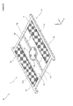
- FIG. 1 is a perspective view showing the configuration of a drive element according to Embodiment 1.
- FIG. FIG. 2(a) is a plan view showing the configuration of the driver according to the first embodiment.
- FIG. 2(b) is a plan view showing the configuration of the movable body according to the first embodiment.
- FIG. 3A is a plan view schematically showing lines for obtaining displacement in the Z-axis direction in simulation according to the first embodiment.
- 3B to 3D are graphs showing simulation results of verifying displacement in the Z-axis direction according to the first embodiment.
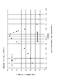
- FIG. 4 is a simulation result showing the relationship between the ratio of the resonant frequency of the driver to the resonant frequency of the movable body and the driving efficiency of the movable part in the common mode according to the first embodiment.
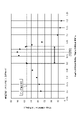
- FIG. 5 is a simulation result showing the relationship between the ratio of the resonance frequency of the driver to the resonance frequency of the movable body and the driving efficiency of the movable part in the negative phase mode according to the first embodiment.
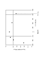
- FIG. 6 is a simulation result showing the relationship between the ratio of the resonant frequency of the driving body to the resonant frequency of the movable body and the resonant frequency of the driving element in the common mode and the negative phase mode according to the first embodiment.
- FIG. 7 is a perspective view showing the configuration of a drive element according to Embodiment 2.
- FIG. FIG. 8 is a plan view showing the configuration of a drive element according to Embodiment 2.
- FIG. 9 is a simulation result showing the relationship between the depth of the slit and the driving efficiency of the movable portion according to the second embodiment.
- FIG. 10 is a simulation result showing the relationship between the ratio of the resonant frequency of the driver to the resonant frequency of the movable body and the driving efficiency of the movable part in the common mode according to the second embodiment.
- FIG. 11 is a simulation result showing the relationship between the ratio of the resonance frequency of the driver to the resonance frequency of the movable body and the driving efficiency of the movable part in the negative phase mode according to the second embodiment.
- each figure is labeled with mutually orthogonal X, Y, and Z axes.
- the Y-axis direction is a direction parallel to the rotation axis of the driving element, and the Z-axis direction is a direction perpendicular to the reflecting surface arranged on the movable portion.
- FIG. 1 is a perspective view showing the configuration of a driving element 1 according to Embodiment 1.
- FIG. 1 is a perspective view showing the configuration of a driving element 1 according to Embodiment 1.
- the drive element 1 includes a pair of drive portions 11, a pair of fixed portions 12, a pair of support portions 13, a movable portion 14, and a pair of connection portions 15.
- a reflecting surface 20 is arranged on the upper surface of the movable portion 14 to configure the optical deflection element 2 .
- the driving element 1 has a shape symmetrical in the X-axis direction and the Y-axis direction in plan view.
- the pair of drive units 11 are arranged side by side in the X-axis direction. In a plan view, the shape and size of the pair of drive portions 11 are the same. The shape of the driving portion 11 is rectangular in plan view. The pair of drive portions 11 are arranged such that the inner (movable portion 14 side) ends are parallel to the Y-axis.
- the pair of fixing parts 12 are arranged so as to sandwich the pair of driving parts 11 in the X-axis direction.
- the pair of fixed portions 12 has a constant width in the X-axis direction and extends parallel to the Y-axis direction.
- the driving element 1 is installed on the installation surface by installing the fixing portion 12 on the installation surface.
- the pair of fixed portions 12 has inner boundaries connected to outer boundaries of the pair of drive portions 11 and the pair of support portions 13 .
- the pair of support portions 13 are arranged so as to sandwich the pair of drive portion 11 and movable portion 14 in the Y-axis direction.
- the pair of support portions 13 has a constant width in the Y-axis direction and extends parallel to the X-axis direction.
- the outer boundaries in the X-axis direction of the pair of support portions 13 are connected to the inner boundaries in the X-axis direction of the pair of fixed portions 12 .
- the pair of support portions 13 has both ends in the X-axis direction connected to the boundary of the pair of drive portions 11 in the Y-axis direction.
- Each drive portion 11 is connected to the support portion 13 over the entire width in the X-axis direction. That is, in the first embodiment, the slit S1 (see FIGS. 7 and 8) extending in the X-axis direction is not provided between the supporting portion 13 and the driving portion 11, unlike the second embodiment described later.
- the movable part 14 is arranged between the pair of driving parts 11 .
- the center position of the movable portion 14 coincides with the intermediate position of the pair of drive portions 11 in the X-axis direction.
- the center position of the movable portion 14 coincides with the intermediate position of the pair of support portions 13 in the Y-axis direction.
- the shape of the movable portion 14 is circular in plan view.
- the shape of the movable portion 14 in plan view may be a shape other than a circle, such as a square.
- a reflecting surface 20 is arranged on the upper surface of the movable portion 14 .
- the reflective surface 20 is arranged by forming a reflective film on the upper surface of the movable portion 14 by, for example, vapor deposition.
- the reflecting surface 20 may be formed by mirror-finishing the upper surface of the movable portion 14 .
- a pair of connection portions 15 connect a pair of support portions 13 and movable portion 14 .
- the pair of connection portions 15 extends linearly in the Y-axis direction from the intermediate position of the pair of support portions 13 in the X-axis direction toward the movable portion 14 and is connected to the intermediate position of the movable portion 14 in the X-axis direction.
- the width of the pair of connecting portions 15 in the X-axis direction is constant.
- the lengths of the pair of connecting portions 15 in the Y-axis direction are equal to each other.
- the cross-sectional shape of the connecting portion 15 when cut along a plane parallel to the XZ plane is a rectangle whose upper side is parallel to the XY plane.
- a piezoelectric driving body 11a is arranged on the top surface of the pair of driving parts 11 . That is, the pair of driving units 11 each includes a piezoelectric driving body 11a as a driving source. In plan view, the piezoelectric driver 11a has a rectangular shape. The width of the piezoelectric driving body 11a in the Y-axis direction is substantially the same as the width in the Y-axis direction of the portion of the driving portion 11 sandwiched between the boundaries of the two support portions 13 on the movable portion 14 side. Also, the outer boundary of the piezoelectric driving body 11 a coincides with the inner boundary of the fixed portion 12 .
- the piezoelectric driver 11a has a laminated structure in which electrode layers are arranged above and below a piezoelectric thin film having a predetermined thickness.
- the piezoelectric thin film is made of a piezoelectric material having a high piezoelectric constant, such as lead zirconate titanate (PZT).
- the electrodes are made of a material with low electric resistance and high heat resistance, such as platinum (Pt).
- the piezoelectric driving body 11a is arranged by forming a layer structure including a piezoelectric thin film and upper and lower electrodes on the upper surface of the substrate included in the area of the piezoelectric driving body 11a by sputtering or the like.
- the base material of the drive element 1 has the same outline as the drive element 1 in plan view and has a constant thickness.
- a reflective surface 20 and a piezoelectric driver 11a are arranged in corresponding regions of the top surface of the substrate. Further, a predetermined material is laminated on the lower surface of the portion of the base material corresponding to the fixing portion 12 to increase the thickness of the fixing portion 12 .
- the material laminated in the fixed part 12 may be a material different from that of the base material, or may be the same material as that of the base material.
- the base material is, for example, integrally formed of silicon or the like.
- the material constituting the base material is not limited to silicon, and may be other materials.
- Materials constituting the substrate are preferably materials having high mechanical strength and Young's modulus, such as metals, crystals, glass, and resins. As such materials, in addition to silicon, titanium, stainless steel, Elinvar, brass alloys, and the like can be used. The same applies to the material laminated on the base material in the fixed part 12 .
- the pair of driving portions 11 bends in the Z-axis direction when a driving signal is supplied to the piezoelectric driving bodies 11a from a driving circuit (not shown). Accordingly, the pair of support portions 13 bends in the Z-axis direction. As a result, the connection portion 15 is twisted about the rotation axis R0, and the movable portion 14 is rotated about the rotation axis R0. Accordingly, the reflecting surface 20 rotates about the rotation axis R0.
- the reflecting surface 20 reflects light incident from above the movable portion 14 in a direction corresponding to the swing angle of the movable portion 14 .
- light for example, laser light
- the reflecting surface 20 reflects light incident from above the movable portion 14 in a direction corresponding to the swing angle of the movable portion 14 .
- the drive element 1 is configured such that the resonance frequency of the drive body B1 and the resonance frequency of the movable body B2 are substantially equal.
- the driving body B ⁇ b>1 is composed of a pair of driving portions 11 and a pair of supporting portions 13 of the driving element 1 .
- the movable body B2 is composed of the movable portion 14, the pair of connecting portions 15, and the reflecting surface 20 of the driving element 1.
- the movable body B2 is the remaining structure of the driving element 1 excluding the driving body B1 and the pair of fixed portions 12 .
- the vibration mode targeted when identifying the resonance frequency of the driving body B1 is the vibration of the pair of driving parts 11 in the Z-axis direction, with the connection surface between the driving body B1 and the fixed part 12 (see FIG. 1) as the fixed surface. are opposite directions to each other, and the supporting portion 13 near the connecting portion 15 (see FIG. 2(b)) rotates and vibrates about the rotation axis R0.
- the fixing surface of the driving body B1 is a surface P1 that is a combination of the connecting surface between the driving portion 11 and the fixing portion 12 and the connecting surface between the supporting portion 13 and the fixing portion 12.
- the plane P1 is parallel to the YZ plane and positioned on the X-axis positive side and the X-axis negative side of the driver B1 corresponding to the pair of fixed portions 12 .
- the vibration mode targeted when identifying the resonance frequency of the movable body B2 is a mode in which the reflecting surface 20 rotationally vibrates around the rotation axis R0 with the connection surface between the movable body B2 and the driving body B1 as a fixed surface.
- the fixed surface of the movable body B2 is the surface P2, which is the connection surface between the pair of connection portions 15 and the pair of support portions 13 (see FIG. 2(a)).
- the plane P2 is parallel to the XZ plane and positioned on the Y-axis positive side and the Y-axis negative side of the movable body B2 corresponding to the pair of connecting portions 15 .
- the resonance frequency of the driving body B1 and the resonance frequency of the movable body B2 are substantially equal, the driving efficiency of the movable part 14 and the reflecting surface 20 can be increased, as will be described later.
- the driving efficiency of the movable part 14 and the reflecting surface 20 is enhanced by making the resonance frequency of the driving body B1 and the resonance frequency of the movable body B2 substantially equal.
- the inventor drove the drive unit 11 and verified the Z-axis displacement of the support unit 13 caused by the drive and the Z-axis direction displacement of the movable unit 14 and the reflecting surface 20 caused by the drive. did.
- the displacement of the support portion 13 in the Z-axis direction is determined by lines extending in the positive and negative directions of the X-axis from the central position of the support portion 13 in the X-axis direction and the Y-axis direction. Acquired along L1.
- the displacements of the movable portion 14 and the reflecting surface 20 in the Z-axis direction were obtained along a line L2 extending from the center of the movable portion 14 and the reflecting surface 20 in the positive direction of the X-axis and the negative direction of the X-axis.
- Figures 3(b) to (d) are graphs showing the displacement in the Z-axis direction obtained by this simulation.
- the horizontal axis indicates the position (position in the X-axis direction) along the lines L1 and L2.
- a value 0 on the horizontal axis indicates the position of the rotation axis R0, where the position in the positive direction of the X-axis is indicated by a positive value and the position in the negative direction of the X-axis is indicated by a negative value.
- the vertical axis indicates the amount of displacement in the Z-axis direction on lines L1 and L2.
- a value of 0 on the vertical axis indicates the position when the drive unit 11 is not driven.
- the values on the vertical axis are the absolute values of the displacement amount when the position of the line L2 in the X-axis direction is +500 ⁇ m or ⁇ 500 ⁇ m, and are obtained by normalizing the values of the lines L1 and L2.
- FIG. 3B is a graph when fa ⁇ fm
- FIG. 3(d) is a graph in the case of fa>fm.
- the deformation of the support portion 13 is smaller than that in FIG. being rotated. That is, in the case of FIG. 3C, compared to FIG. 3B, the inclination of the movable body B2 is greater than that of the driving body B1, and the leverage ratio is large.
- the deformation of the support portion 13 is smaller than that in FIG. is rotated to That is, in the case of FIG. 3D, compared to FIG. 3C, the inclination of the movable body B2 is greater than that of the driving body B1, and the leverage ratio is large.
- FIG. 4 is a graph showing simulation results of the driving efficiency of the movable part 14 in a mode in which the direction of vibration of the driving body B1 and the direction of vibration of the movable body B2 are the same (hereinafter referred to as "in-phase mode").
- the horizontal axis is the ratio R
- the vertical axis is the full angle of the rotation angle of the movable portion 14 (reflecting surface 20) per 10 Vpp.
- the level of the rotation angle (1° to 2°) of the movable portion 14 when the ratio R is about 4 is indicated by a dashed line.
- the ratio R when the ratio R is 0.7 or more and 1.2 or less, that is, when the ratio R is substantially equal to 1, the rotation of the movable part 14 is greater than when the ratio R is about 4. It is possible to increase the moving angle by several steps.
- the rotation angle of the movable portion 14 was the largest (76.11°). That is, when the ratio R between the resonance frequency fa of the driving body B1 and the resonance frequency fm of the movable body B2 was slightly smaller than 1, the driving efficiency of the movable portion 14 was the highest.
- the value of 80% of the peak value (76.11°) of the rotation angle is indicated by a dashed line.
- the rotation angle becomes 80% or more with respect to the peak value of the rotation angle when the ratio R is about 0.918 or more and about 1.025 or less. Therefore, if the ratio R is set to 0.9 or more and 1.03 or less, the rotation angle of the movable portion 14 can be set sufficiently large, and the driving efficiency of the movable portion 14 can be enhanced.
- FIG. 5 is a graph showing simulation results of the driving efficiency of the movable part 14 in a mode in which the direction of vibration of the driving body B1 and the direction of vibration of the movable body B2 are opposite directions (hereinafter referred to as "reverse phase mode"). is.
- the level of the rotation angle (1° to 2°) of the movable portion 14 when the ratio R is about 4 is indicated by a dashed line.
- the ratio R is 0.7 or more and 1.2 or less, that is, when the ratio R is substantially equal to 1, the rotation of the movable part 14 is greater than when the ratio R is about 4. It is possible to increase the moving angle by several steps.
- the rotation angle of the movable portion 14 was the largest (70.64°). That is, when the ratio R between the resonance frequency fa of the driving body B1 and the resonance frequency fm of the movable body B2 was slightly smaller than 1, the driving efficiency of the movable portion 14 was the highest.
- the value of 80% of the peak value (70.64°) of the rotation angle is indicated by a dashed line.
- the rotation angle becomes 80% or more with respect to the peak value of the rotation angle when the ratio R is about 0.897 or more and about 1.019 or less. Therefore, if the ratio R is set to 0.9 or more and 1.03 or less, the rotation angle of the movable portion 14 can be sufficiently increased, and the driving efficiency of the movable portion 14 can be enhanced.
- the ratio R is preferably set in the range of 0.9 or more and 1.03 or less, and more preferably set to around 0.98 in both the in-phase mode and the anti-phase mode. rice field.
- the inventor verified the resonance frequency of the entire drive element 1 by simulation when the drive element 1 was configured so that the ratio R was a value close to 1 in the common-mode and the anti-phase mode.
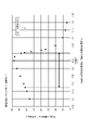
- FIG. 6 is a graph showing simulation results of the resonance frequency of the entire driving element 1 in the common mode and the negative phase mode.
- the horizontal axis is the ratio R
- the vertical axis is the resonance frequency of the driving element 1 as a whole.
- the resonance frequency of the entire element in the common mode and the resonance frequency of the entire element in the anti-phase mode are values separated from each other.
- the ratio R is set to around 1 in the common-phase mode and the anti-phase mode as described above, as shown in FIG. It was confirmed that the resonance frequencies of the whole have values close to each other.
- Embodiment 1 According to Embodiment 1, the following effects are achieved.
- the resonance frequency fa of the driving body B1 consisting of the pair of driving parts 11 and the pair of supporting parts 13 and the resonance frequency fm of the movable body B2 consisting of the movable part 14 and the pair of connecting parts 15 are substantially equal.
- the rotation angle of the movable portion 14 is increased, and the driving efficiency of the movable portion 14 can be enhanced. Therefore, light can be deflected and scanned at higher deflection angles.
- the ratio R of the resonance frequency fa of the driving body B1 to the resonance frequency fm of the movable body B2 is set to 0.9 or more and 1.03 or less in the common-phase mode and the anti-phase mode.
- the rotation angle of the movable portion 14 can be set to about 80% or more of the peak value. Therefore, by setting the ratio R in this manner, the driving efficiency of the movable portion 14 can be enhanced.
- the driving section 11 has a piezoelectric driving body 11a as a driving source. Thereby, the movable part 14 can be driven with high driving efficiency.
- each drive portion 11 is connected to the support portion 13 over the entire width in the X-axis direction.
- a slit S1 extending in the X-axis direction is provided between the support portion 13 and the drive portion 11 .
- FIG. 7 is a perspective view showing the configuration of the drive element 1 according to Embodiment 2
- FIG. 8 is a plan view showing the configuration of the drive element 1 according to Embodiment 2.
- slits S1 are formed at both ends of the pair of driving parts 11 in the Y-axis direction.
- the slit S1 is formed so as to extend outward by a predetermined length (depth) from the inner (movable portion 14 side) end of the pair of driving portions 11 .
- the slits S1 are formed by cutting out the driving portions 11 linearly from the inner ends of the pair of driving portions 11 toward the outside.
- the width and length (depth) of the four slits S1 are equal to each other.
- a gap is formed between the drive portion 11 and the support portion 13 by the four slits S1.
- the driving body B1 is composed of the pair of driving portions 11 and the pair of supporting portions 13 of the driving element 1.
- the movable body B ⁇ b>2 is composed of the movable portion 14 , the pair of connecting portions 15 and the reflecting surface 20 of the driving element 1 .
- the fixing surface of the driving body B1 and the fixing surface of the movable body B2 are surfaces P1 and P2 similar to those of the first embodiment, respectively.
- the vibration mode targeted when identifying the resonance frequency of the movable body B2 is also the same as in the first embodiment.
- the drive element 1 is configured such that the resonance frequency fa of the drive body B1 and the resonance frequency fm of the movable body B2 are substantially equal.
- slits S1 having a predetermined length (depth) are formed near the boundaries between the pair of driving portions 11 and the pair of supporting portions 13. At the positions of these slits S1, the pair of driving portions 11 and the pair of is separated from the support portion 13 of the . As a result, driving efficiency of the movable portion 14 and the reflecting surface 20 can be increased compared to the first embodiment in which these slits S1 are not formed.
- the inventor verified the relationship between the depth of the slit S1 in the X-axis direction and the drive efficiency of the movable portion 14 by simulation.
- FIG. 9 is a simulation result showing the relationship between the depth of the slit S1 and the driving efficiency of the movable portion 14.
- the horizontal axis of FIG. 9 plots the depth of the slit S1 when the slit S1 extends to the position (inflection point P0) where the slope of the amplitude waveform of the support portion 13 switches between increasing and decreasing, and the depth of the slit S1 is 0. depth is specified.
- a positive value on the horizontal axis indicates a value at which the depth of the slit S1 decreases, and a negative value on the horizontal axis indicates a value at which the depth of the slit S1 increases.
- the vertical axis of FIG. 9 indicates the value normalized by the maximum value of the simulation result for all angles of the rotation angle of the movable portion 14 (reflecting surface 20) per 1 Vpp.
- the depth of the slit S1 (the value on the horizontal axis in FIG. 9) was changed to -510 ⁇ m, -369 ⁇ m, -255 ⁇ m, 0 ⁇ m, 423 ⁇ m and 846 ⁇ m.
- the plot with the horizontal axis of 846 ⁇ m corresponds to the case where the depth of the slit S1 is 0, that is, the slit S1 is not formed as in the first embodiment.
- the depth of the slit S1 is 846 ⁇ m.
- the driving efficiency of the movable portion 14 gradually increased as the slit S1 became deeper.
- the driving efficiency of the movable portion 14 is maximized, and thereafter, the driving efficiency of the movable portion 14 decreases as the slit S1 becomes deeper.
- the leftmost plot of FIG. 9 when the depth of the slit S1 is too large, the driving efficiency of the movable portion 14 is lower than when the slit S1 is not provided (the rightmost plot). From this, it was confirmed that the depth of the slit S1 has a range suitable for improving the driving efficiency.
- the drive efficiency of the movable part 14 is higher than when there is no slit S1 at least within the range up to the depth corresponding to the second plot from the left.
- the depth (length in the X-axis direction) of the slit S1 corresponding to the second plot from the left is 369 ⁇ m from 864 ⁇ m, which is the depth of the slit S1 when the slit S1 is extended to the inflection point P0. extended depth.
- the driving efficiency of the movable part 14 is can be made higher than without the slit S1. Also, from the verification result of FIG. 9, it can be seen that the driving efficiency of the movable portion 14 can be maximized at the depth up to the inflection point P0 in this range.
- the depth of the slit S1 in the X-axis direction within a range whose upper limit is about 40% deeper than the depth up to the inflection point P0.
- the drive element 1 is configured such that the depth of the slit S1 is positioned at the inflection point P0 when the ratio R between the resonance frequency fa of the drive body B1 and the resonance frequency fm of the movable body B2 is 1.
- the ratio R when varying the ratio R, the depth of the slit S1 was fixed and only the length of the support portion 13 in the X-axis direction was varied.
- FIG. 10 is a graph showing simulation results of driving efficiency of the movable portion 14 in the common mode according to the second embodiment.
- the level of the rotation angle (1° to 2°) of the movable portion 14 when the ratio R is about 4 is indicated by a dashed line.
- the ratio R when the ratio R is 0.7 or more and 1.2 or less, that is, when the ratio R is substantially equal to 1, the rotation of the movable part 14 is greater than when the ratio R is about 4. It is possible to increase the moving angle by several steps.
- the rotation angle of the movable portion 14 has the largest value (74.39°). That is, when the ratio R between the resonance frequency fa of the driving body B1 and the resonance frequency fm of the movable body B2 was slightly smaller than 1, the driving efficiency of the movable portion 14 was the highest.
- the value of 80% of the peak value (74.39°) of the rotation angle is indicated by a dashed line.
- the rotation angle becomes 80% or more with respect to the peak value of the rotation angle when the ratio R is about 0.934 or more and about 1.010 or less. Therefore, if the ratio R is set to 0.9 or more and 1.02 or less, the rotation angle of the movable portion 14 can be set sufficiently large, and the driving efficiency of the movable portion 14 can be enhanced.
- FIG. 11 is a graph showing simulation results of the driving efficiency of the movable part 14 in the reverse phase mode according to the second embodiment.
- the level of the rotation angle (1° to 2°) of the movable portion 14 when the ratio R is about 4 is indicated by a dashed line.
- the ratio R when the ratio R is 0.7 or more and 1.2 or less, that is, when the ratio R is substantially equal to 1, the rotation of the movable part 14 is greater than when the ratio R is about 4. It is possible to increase the moving angle by several steps.
- the rotation angle of the movable portion 14 was the largest (77.05°). That is, when the ratio R between the resonance frequency fa of the driving body B1 and the resonance frequency fm of the movable body B2 was slightly smaller than 1, the driving efficiency of the movable portion 14 was the highest.
- the value of 80% of the peak value (77.05°) of the rotation angle is indicated by a dashed line.
- the rotation angle becomes 80% or more with respect to the peak value of the rotation angle when the ratio R is about 0.776 or more and about 1.004 or less. Therefore, if the ratio R is set to 0.7 or more and 1.01 or less, the rotation angle of the movable portion 14 can be sufficiently increased, and the driving efficiency of the movable portion 14 can be enhanced.
- the driving efficiency of the movable part 14 can be improved by configuring the driving element 1 so that the resonance frequency fa of the driving body B1 and the resonance frequency fm of the movable body B2 are substantially equal to each other.
- the ratio R is preferably set in the range of 0.9 or more and 1.02 or less, and more preferably set in the vicinity of 0.98.
- the ratio R is preferably set in the range of 0.7 or more and 1.01 or less, and more preferably set in the vicinity of 0.95.
- the depth of the slit S1 is preferably set near the inflection point P0.
- the drive efficiency of the movable portion 14 can be enhanced from both sides of the ratio R and the depth of the slit S1.
- the resonance frequency fa of the driving body B1 and the resonance frequency fm of the movable body B2 are substantially equal.
- the rotation angle of the movable portion 14 is increased, and the driving efficiency of the movable portion 14 can be enhanced. Therefore, light can be deflected and scanned at higher deflection angles.
- the driving section 11 can drive the supporting section 13 more efficiently, and the driving efficiency of the movable section 14 can be increased. As a result, the driving efficiency of the reflecting surface 20 can be increased, and light can be deflected and scanned at a higher deflection angle.
- the pair of support portions 13 is formed by forming a slit S1 in the direction in which the pair of drive portions 11 are arranged (X-axis direction) from the end of the pair of drive portions 11 on the movable portion 14 side. and a pair of driving portions 11, a gap is formed between them. Thereby, a gap can be continuously formed from the end of the pair of driving portions 11 on the movable portion 14 side, and the driving efficiency of the movable portion 14 can be improved smoothly.
- the ratio R of the resonance frequency fa of the driving body B1 to the resonance frequency fm of the movable body B2 is set to 0.9 or more and 1.02 or less. can be set to about 80% or more of the peak value. Therefore, by setting the ratio R in this manner, the driving efficiency of the movable portion 14 can be enhanced.
- the ratio R of the resonance frequency fa of the driving body B1 to the resonance frequency fm of the movable body B2 is set to 0.7 or more and 1.01 or less. 14 can be set to about 80% or more of the peak value. Therefore, by setting the ratio R in this manner, the driving efficiency of the movable portion 14 can be enhanced.
- the shape of the drive element 1 in plan view and the dimensions of each part of the drive element 1 can be changed as appropriate.
- the shape and width of the piezoelectric driving body 11a in plan view can also be changed as appropriate.
- the thickness, length, width and shape of the fixed portion 12 can be changed as appropriate.
- the thickness of fixed portion 12 may be the same as the thickness of drive portion 11 and support portion 13 .
- the thickness, width and shape of the fixing portion 12 can be changed as appropriate as long as the drive element 1 can be installed on the installation surface.
- both ends of the pair of support portions 13 are connected to the pair of fixed portions 12 , but both ends of the support portion 13 may not be connected to the fixed portions 12 .
- the width of the fixed portion 12 in the Y-axis direction is set equal to the width of the drive portion 11 in the Y-axis direction, and both ends of the support portion 13 are connected only to both edges of the drive portion 11 in the Y-axis direction. good too.
- the fixed surface of the driving body B ⁇ b>1 becomes the connecting surface between the driving portion 11 and the fixed portion 12 .
- both ends of one fixing portion 12 in the Y-axis direction and both ends of the other fixing portion 12 in the Y-axis direction are further connected in the X-axis direction to form a fixing portion.
- the fixing portion 12 may be configured so as to surround the pair of drive portions 11 and the pair of support portions 13 .
- the gap is formed between the drive portion 11 and the support portion 13 by continuously forming the slits S1 having a constant width in the Y-axis direction. It is not something that can be done.
- the width of the gap in the Y-axis direction may change according to the position in the X-axis direction by changing the width of the drive portion 11 or the support portion 13 in the X-axis direction.
- the gaps may not be continuous in the X-axis direction, and may be intermittently formed in the X-axis direction.
- the driving body B1 is composed of the pair of driving parts 11 and the pair of supporting parts 13, and the movable body B2 is composed of a movable portion 14 , a pair of connecting portions 15 and a reflecting surface 20 .
- the drive element 1 is configured such that the resonance frequency fa of the drive body B1 and the resonance frequency fm of the movable body B2 are substantially equal. Thereby, the driving efficiency of the movable portion 14 and the reflecting surface 20 can be enhanced.
- the driving element 1 may be used as an element other than the optical deflection element 2.
- the reflecting surface 20 may not be arranged on the movable portion 14, and a member other than the reflecting surface 20 may be arranged.
- the movable body B2 in this case is composed of the movable portion 14, the pair of connection portions 15, and other members.
Abstract
A drive element (1) comprises a pair of drive parts (11) disposed along one direction, a movable part (14) disposed between the pair of drive parts (11), a pair of support parts (13) disposed with the pair of drive parts (11) and the movable part (14) therebetween, a pair of connecting parts (15) that connect the pair of support parts (13) and the movable part (14), and a fixing part (12) connected to each of at least the pair of drive parts (11) in the arrangement direction of the drive parts (11). The resonance frequency of a drive body (B1) comprising the pair of drive parts (11) and the pair of support parts (13) and the resonance frequency of a movable body (B2) comprising the movable part (14) and the pair of connecting parts (15) are substantially equal.
Description
本発明は、回動軸について可動部を回動させる駆動素子および当該駆動素子を用いた光偏向素子に関する。
The present invention relates to a driving element that rotates a movable portion about a rotation axis and an optical deflection element using the driving element.
近年、MEMS(Micro Electro Mechanical System)技術を用いて可動部を回動させる駆動素子が開発されている。この種の駆動素子では、可動部に反射面を配置することにより、反射面に入射する光を所定の振れ角で走査させることができる。この種の駆動素子は、たとえば、ヘッドアップディスプレイやヘッドマウントディスプレイ等の画像表示装置に搭載される。この他、レーザ光を用いて物体を検出するレーザレーダ等にも、この種の駆動素子が用いられ得る。
In recent years, driving elements that rotate movable parts using MEMS (Micro Electro Mechanical System) technology have been developed. In this type of driving element, by arranging the reflecting surface on the movable portion, the light incident on the reflecting surface can be scanned at a predetermined deflection angle. This type of drive element is mounted, for example, in an image display device such as a head-up display or a head-mounted display. In addition, this type of drive element can be used in a laser radar or the like that detects an object using laser light.
以下の非特許文献1には、互いに平行な一対の支持部を駆動することにより、回動軸についてミラーを回動させる駆動素子が記載されている。この駆動素子では、一対の支持部の両端にそれぞれ駆動部が配置される。これら駆動部によって、一対の支持部の両端が上下に駆動される。これにより、一対の支持部の中間を連結する連結部に捩れが生じ、当該連結部の中央に配置された可動部が回動する。こうして、可動部に配置されたミラーが、連結部により規定される回動軸について回動する。
The following Non-Patent Document 1 describes a drive element that rotates a mirror about a rotation axis by driving a pair of support portions parallel to each other. In this drive element, drive portions are arranged at both ends of a pair of support portions. Both ends of the pair of support portions are driven up and down by these drive portions. As a result, the connecting portion that connects the middle of the pair of support portions is twisted, and the movable portion arranged in the center of the connecting portion rotates. Thus, the mirror arranged on the movable portion rotates about the rotation axis defined by the connecting portion.
上記構成の駆動素子は、簡素な構成であるため簡易に生成できる。しかし、この駆動素子では、1Vpp当たりの可動部の回動角が小さいため、可動部の駆動効率をより向上させることが要求される。
The drive element with the above configuration can be easily generated because it has a simple configuration. However, in this driving element, since the rotation angle of the movable portion per 1 Vpp is small, it is required to further improve the driving efficiency of the movable portion.
かかる課題に鑑み、本発明は、可動部の駆動効率をより高めることが可能な駆動素子および光偏向素子を提供することを目的とする。
In view of such problems, it is an object of the present invention to provide a driving element and an optical deflection element capable of further increasing the driving efficiency of the movable portion.
本発明の第1の態様は、駆動素子に関する。この態様に係る駆動素子は、一方向に並んで配置された一対の駆動部と、前記一対の駆動部の間に配置された可動部と、前記一対の駆動部および前記可動部を挟んで配置される一対の支持部と、前記一対の支持部と前記可動部とを接続する一対の接続部と、前記駆動部の並び方向において、少なくとも前記一対の駆動部にそれぞれ接続される固定部と、を備える。前記一対の駆動部および前記一対の支持部からなる駆動体の共振周波数と、前記可動部および前記一対の接続部からなる可動体の共振周波数とが略等しい。
A first aspect of the present invention relates to a drive element. The driving element according to this aspect includes a pair of driving portions arranged side by side in one direction, a movable portion arranged between the pair of driving portions, and a pair of driving portions and the movable portion arranged between the pair of driving portions. a pair of support portions connected to each other, a pair of connection portions connecting the pair of support portions and the movable portion, and fixed portions respectively connected to at least the pair of drive portions in the direction in which the drive portions are arranged; Prepare. The resonant frequency of the driving body composed of the pair of driving portions and the pair of supporting portions is substantially equal to the resonant frequency of the movable body composed of the movable portion and the pair of connecting portions.
本態様に係る駆動素子によれば、駆動体の共振周波数と可動体の共振周波数とが略等しい。これにより、後述する実施形態に示すように、可動部の回動角が大きくなり、可動部の駆動効率を高めることができる。
According to the drive element according to this aspect, the resonance frequency of the drive body and the resonance frequency of the movable body are substantially equal. As a result, as shown in an embodiment to be described later, the rotation angle of the movable portion is increased, and the driving efficiency of the movable portion can be enhanced.
本発明の第2の態様は、光偏向素子に関する。この態様に係る光偏向素子は、第1の態様に係る駆動素子と、前記可動部に配置された反射面と、を備える。
A second aspect of the present invention relates to an optical deflection element. An optical deflection element according to this aspect includes the driving element according to the first aspect, and a reflecting surface arranged on the movable portion.
本態様に係る駆動素子によれば、第1の態様に係る駆動素子を備えるため、可動部の駆動効率を高めることができる。よって、反射面の駆動効率を高めることができ、より高い振れ角で、光を偏向および走査させることができる。
According to the driving element according to this aspect, since the driving element according to the first aspect is provided, it is possible to increase the driving efficiency of the movable portion. Therefore, the driving efficiency of the reflecting surface can be increased, and the light can be deflected and scanned at a higher deflection angle.
以上のとおり、本発明によれば、可動部の駆動効率をより高めることが可能な駆動素子および光偏向素子を提供できる。
As described above, according to the present invention, it is possible to provide a driving element and an optical deflection element capable of further increasing the driving efficiency of the movable portion.
本発明の効果ないし意義は、以下に示す実施形態の説明により更に明らかとなろう。ただし、以下に示す実施形態は、あくまでも、本発明を実施化する際の一つの例示であって、本発明は、以下の実施形態に記載されたものに何ら制限されるものではない。
The effects and significance of the present invention will become clearer from the description of the embodiments shown below. However, the embodiment shown below is merely one example of the implementation of the present invention, and the present invention is not limited to the embodiments described below.
ただし、図面はもっぱら説明のためのものであって、この発明の範囲を限定するものではない。
However, the drawings are for illustration only and do not limit the scope of the present invention.
以下、本発明の実施形態について、図面を参照して説明する。便宜上、各図には互いに直交するX、Y、Z軸が付記されている。Y軸方向は、駆動素子の回動軸に平行な方向であり、Z軸方向は、可動部に配置された反射面に垂直な方向である。
Hereinafter, embodiments of the present invention will be described with reference to the drawings. For convenience, each figure is labeled with mutually orthogonal X, Y, and Z axes. The Y-axis direction is a direction parallel to the rotation axis of the driving element, and the Z-axis direction is a direction perpendicular to the reflecting surface arranged on the movable portion.
<実施形態1>
図1は、実施形態1に係る、駆動素子1の構成を示す斜視図である。 <Embodiment 1>
FIG. 1 is a perspective view showing the configuration of adriving element 1 according to Embodiment 1. FIG.
図1は、実施形態1に係る、駆動素子1の構成を示す斜視図である。 <
FIG. 1 is a perspective view showing the configuration of a
駆動素子1は、一対の駆動部11と、一対の固定部12と、一対の支持部13と、可動部14と、一対の接続部15とを備える。可動部14の上面に反射面20が配置されて、光偏向素子2が構成される。駆動素子1は、平面視において、X軸方向およびY軸方向に対称な形状である。
The drive element 1 includes a pair of drive portions 11, a pair of fixed portions 12, a pair of support portions 13, a movable portion 14, and a pair of connection portions 15. A reflecting surface 20 is arranged on the upper surface of the movable portion 14 to configure the optical deflection element 2 . The driving element 1 has a shape symmetrical in the X-axis direction and the Y-axis direction in plan view.
一対の駆動部11は、X軸方向に並んで配置されている。平面視において、一対の駆動部11の形状および広さは、互いに同じである。駆動部11の形状は、平面視において長方形である。一対の駆動部11は、内側(可動部14側)の端が、Y軸に平行となるように配置される。
The pair of drive units 11 are arranged side by side in the X-axis direction. In a plan view, the shape and size of the pair of drive portions 11 are the same. The shape of the driving portion 11 is rectangular in plan view. The pair of drive portions 11 are arranged such that the inner (movable portion 14 side) ends are parallel to the Y-axis.
一対の固定部12は、一対の駆動部11をX軸方向に挟むように配置されている。一対の固定部12は、X軸方向の幅が一定であり、Y軸方向に平行に延びている。駆動素子1は、固定部12を被設置面に設置することにより、被設置面に設置される。一対の固定部12は、内側の境界が一対の駆動部11および一対の支持部13の外側の境界に繋がっている。
The pair of fixing parts 12 are arranged so as to sandwich the pair of driving parts 11 in the X-axis direction. The pair of fixed portions 12 has a constant width in the X-axis direction and extends parallel to the Y-axis direction. The driving element 1 is installed on the installation surface by installing the fixing portion 12 on the installation surface. The pair of fixed portions 12 has inner boundaries connected to outer boundaries of the pair of drive portions 11 and the pair of support portions 13 .
一対の支持部13は、一対の駆動部11および可動部14をY軸方向に挟むように配置されている。一対の支持部13は、Y軸方向の幅が一定であり、X軸方向に平行に延びている。一対の支持部13は、X軸方向の外側の境界が一対の固定部12のX軸方向の内側の境界に繋がっている。また、一対の支持部13は、X軸方向の両側の端部が、一対の駆動部11のY軸方向の境界に繋がっている。各駆動部11は、X軸方向の全幅において支持部13に繋がっている。すなわち、実施形態1では、後述する実施形態2とは異なり、支持部13と駆動部11との間にX軸方向に延びるスリットS1(図7、8参照)が設けられていない。
The pair of support portions 13 are arranged so as to sandwich the pair of drive portion 11 and movable portion 14 in the Y-axis direction. The pair of support portions 13 has a constant width in the Y-axis direction and extends parallel to the X-axis direction. The outer boundaries in the X-axis direction of the pair of support portions 13 are connected to the inner boundaries in the X-axis direction of the pair of fixed portions 12 . In addition, the pair of support portions 13 has both ends in the X-axis direction connected to the boundary of the pair of drive portions 11 in the Y-axis direction. Each drive portion 11 is connected to the support portion 13 over the entire width in the X-axis direction. That is, in the first embodiment, the slit S1 (see FIGS. 7 and 8) extending in the X-axis direction is not provided between the supporting portion 13 and the driving portion 11, unlike the second embodiment described later.
可動部14は、一対の駆動部11の間に配置されている。X軸方向において、可動部14の中心位置は、一対の駆動部11の中間位置に一致する。また、Y軸方向において、可動部14の中心位置は、一対の支持部13の中間位置に一致する。ここでは、可動部14の形状が、平面視において円形である。平面視における可動部14の形状は、正方形等、円形以外の形状であってもよい。可動部14の上面に反射面20が配置されている。反射面20は、たとえば、蒸着等によって、可動部14の上面に反射膜を形成することにより配置される。可動部14の上面が鏡面仕上げされて反射面20が形成されてもよい。
The movable part 14 is arranged between the pair of driving parts 11 . The center position of the movable portion 14 coincides with the intermediate position of the pair of drive portions 11 in the X-axis direction. In addition, the center position of the movable portion 14 coincides with the intermediate position of the pair of support portions 13 in the Y-axis direction. Here, the shape of the movable portion 14 is circular in plan view. The shape of the movable portion 14 in plan view may be a shape other than a circle, such as a square. A reflecting surface 20 is arranged on the upper surface of the movable portion 14 . The reflective surface 20 is arranged by forming a reflective film on the upper surface of the movable portion 14 by, for example, vapor deposition. The reflecting surface 20 may be formed by mirror-finishing the upper surface of the movable portion 14 .
一対の接続部15は、一対の支持部13と可動部14とを接続する。一対の接続部15は、一対の支持部13のX軸方向の中間位置から可動部14に向かって、Y軸方向に直線状に延びて、可動部14のX軸方向の中間位置に接続されている。一対の接続部15のX軸方向の幅は一定である。一対の接続部15のY軸方向の長さは、互いに等しい。X-Z平面に平行な平面で切断したときの接続部15の断面形状は、上辺がX-Y平面に平行な矩形である。
A pair of connection portions 15 connect a pair of support portions 13 and movable portion 14 . The pair of connection portions 15 extends linearly in the Y-axis direction from the intermediate position of the pair of support portions 13 in the X-axis direction toward the movable portion 14 and is connected to the intermediate position of the movable portion 14 in the X-axis direction. ing. The width of the pair of connecting portions 15 in the X-axis direction is constant. The lengths of the pair of connecting portions 15 in the Y-axis direction are equal to each other. The cross-sectional shape of the connecting portion 15 when cut along a plane parallel to the XZ plane is a rectangle whose upper side is parallel to the XY plane.
一対の駆動部11の上面には、圧電駆動体11aが配置されている。すなわち、一対の駆動部11は、駆動源として、それぞれ、圧電駆動体11aを備える。平面視において、圧電駆動体11aは、長方形の形状である。Y軸方向における圧電駆動体11aの幅は、2つの支持部13の可動部14側の境界で挟まれる駆動部11の部分のY軸方向の幅と略同じである。また、圧電駆動体11aの外側の境界は、固定部12の内側の境界に一致している。
A piezoelectric driving body 11a is arranged on the top surface of the pair of driving parts 11 . That is, the pair of driving units 11 each includes a piezoelectric driving body 11a as a driving source. In plan view, the piezoelectric driver 11a has a rectangular shape. The width of the piezoelectric driving body 11a in the Y-axis direction is substantially the same as the width in the Y-axis direction of the portion of the driving portion 11 sandwiched between the boundaries of the two support portions 13 on the movable portion 14 side. Also, the outer boundary of the piezoelectric driving body 11 a coincides with the inner boundary of the fixed portion 12 .
圧電駆動体11aは、所定厚みの圧電体薄膜の上下にそれぞれ電極層が配置された積層構造を有する。圧電体薄膜は、たとえば、チタン酸ジルコン酸鉛(PZT)等の高い圧電定数を有する圧電材料からなっている。電極は、白金(Pt)等の、電気抵抗が低く、耐熱性が高い材料からなっている。圧電駆動体11aは、圧電体薄膜および上下の電極を含む層構造を、スパッタ法等によって、圧電駆動体11aの領域に含まれる基材の上面に形成することにより配置される。
The piezoelectric driver 11a has a laminated structure in which electrode layers are arranged above and below a piezoelectric thin film having a predetermined thickness. The piezoelectric thin film is made of a piezoelectric material having a high piezoelectric constant, such as lead zirconate titanate (PZT). The electrodes are made of a material with low electric resistance and high heat resistance, such as platinum (Pt). The piezoelectric driving body 11a is arranged by forming a layer structure including a piezoelectric thin film and upper and lower electrodes on the upper surface of the substrate included in the area of the piezoelectric driving body 11a by sputtering or the like.
駆動素子1の基材は、平面視において駆動素子1と同じ輪郭で、且つ、一定厚みを有する。基材上面の対応する領域に、反射面20および圧電駆動体11aが配置される。また、基材の固定部12に対応する部分の下面に、さらに所定の材料が積層されて、固定部12の厚みが広げられている。固定部12において積層される材料は、基材と異なる材料であってよく、または、基材と同じ材料であってもよい。
The base material of the drive element 1 has the same outline as the drive element 1 in plan view and has a constant thickness. A reflective surface 20 and a piezoelectric driver 11a are arranged in corresponding regions of the top surface of the substrate. Further, a predetermined material is laminated on the lower surface of the portion of the base material corresponding to the fixing portion 12 to increase the thickness of the fixing portion 12 . The material laminated in the fixed part 12 may be a material different from that of the base material, or may be the same material as that of the base material.
基材は、たとえば、シリコン等によって一体形成される。ただし、基材を構成する材料は、シリコンに限らず、他の材料であってもよい。基材を構成する材料は、金属、結晶体、ガラス、樹脂等の機械的強度およびヤング率が高い材料であることが好ましい。このような材料として、シリコンの他、チタン、ステンレス、エリンバー、黄銅合金等を用いることができる。固定部12において基材に積層される材料も同様である。
The base material is, for example, integrally formed of silicon or the like. However, the material constituting the base material is not limited to silicon, and may be other materials. Materials constituting the substrate are preferably materials having high mechanical strength and Young's modulus, such as metals, crystals, glass, and resins. As such materials, in addition to silicon, titanium, stainless steel, Elinvar, brass alloys, and the like can be used. The same applies to the material laminated on the base material in the fixed part 12 .
一対の駆動部11は、図示しない駆動回路から圧電駆動体11aに駆動信号が供給されることにより、Z軸方向に湾曲する。これに伴い、一対の支持部13がZ軸方向に湾曲する。これにより、接続部15が回動軸R0を中心に捩れて、可動部14が回動軸R0について回動する。これに伴い、反射面20が、回動軸R0について回動する。
The pair of driving portions 11 bends in the Z-axis direction when a driving signal is supplied to the piezoelectric driving bodies 11a from a driving circuit (not shown). Accordingly, the pair of support portions 13 bends in the Z-axis direction. As a result, the connection portion 15 is twisted about the rotation axis R0, and the movable portion 14 is rotated about the rotation axis R0. Accordingly, the reflecting surface 20 rotates about the rotation axis R0.
反射面20は、可動部14の上方から入射した光を、可動部14の振り角に応じた方向に反射する。これにより、反射面20に入射した光(たとえば、レーザ光)が、可動部14の回動に伴い偏向されて走査される。
The reflecting surface 20 reflects light incident from above the movable portion 14 in a direction corresponding to the swing angle of the movable portion 14 . As a result, light (for example, laser light) incident on the reflecting surface 20 is deflected and scanned as the movable portion 14 rotates.
ここで、駆動素子1において、駆動体B1の共振周波数と可動体B2の共振周波数とが略等しくなるように、駆動素子1が構成される。図2(a)に示すように、駆動体B1は、駆動素子1のうち、一対の駆動部11および一対の支持部13により構成される。図2(b)に示すように、可動体B2は、駆動素子1のうち、可動部14、一対の接続部15、および反射面20により構成される。すなわち、可動体B2は、駆動素子1から、駆動体B1および一対の固定部12を除いた残りの構成である。
Here, in the drive element 1, the drive element 1 is configured such that the resonance frequency of the drive body B1 and the resonance frequency of the movable body B2 are substantially equal. As shown in FIG. 2( a ), the driving body B<b>1 is composed of a pair of driving portions 11 and a pair of supporting portions 13 of the driving element 1 . As shown in FIG. 2B, the movable body B2 is composed of the movable portion 14, the pair of connecting portions 15, and the reflecting surface 20 of the driving element 1. As shown in FIG. In other words, the movable body B2 is the remaining structure of the driving element 1 excluding the driving body B1 and the pair of fixed portions 12 .
駆動体B1の共振周波数を同定する際に対象とした振動モードは、駆動体B1と固定部12(図1参照)との接続面を固定面として、一対の駆動部11のZ軸方向の振動が互いに逆方向で、接続部15(図2(b)参照)近傍の支持部13が回動軸R0周りに回転振動するモードである。図2(a)の構成では、駆動体B1の固定面は、駆動部11と固定部12との接続面、および、支持部13と固定部12との接続面を合わせた面P1である。面P1は、Y-Z平面に平行であり、一対の固定部12に対応して駆動体B1のX軸正側およびX軸負側に位置している。
The vibration mode targeted when identifying the resonance frequency of the driving body B1 is the vibration of the pair of driving parts 11 in the Z-axis direction, with the connection surface between the driving body B1 and the fixed part 12 (see FIG. 1) as the fixed surface. are opposite directions to each other, and the supporting portion 13 near the connecting portion 15 (see FIG. 2(b)) rotates and vibrates about the rotation axis R0. In the configuration of FIG. 2A, the fixing surface of the driving body B1 is a surface P1 that is a combination of the connecting surface between the driving portion 11 and the fixing portion 12 and the connecting surface between the supporting portion 13 and the fixing portion 12. In FIG. The plane P1 is parallel to the YZ plane and positioned on the X-axis positive side and the X-axis negative side of the driver B1 corresponding to the pair of fixed portions 12 .
可動体B2の共振周波数を同定する際に対象とした振動モードは、可動体B2と駆動体B1との接続面を固定面として、反射面20が回動軸R0周りに回転振動するモードである。図2(b)の構成では、可動体B2の固定面は、一対の接続部15と一対の支持部13(図2(a)参照)との接続面である面P2である。面P2は、X-Z平面に平行であり、一対の接続部15に対応して可動体B2のY軸正側およびY軸負側に位置している。
The vibration mode targeted when identifying the resonance frequency of the movable body B2 is a mode in which the reflecting surface 20 rotationally vibrates around the rotation axis R0 with the connection surface between the movable body B2 and the driving body B1 as a fixed surface. . In the configuration of FIG. 2(b), the fixed surface of the movable body B2 is the surface P2, which is the connection surface between the pair of connection portions 15 and the pair of support portions 13 (see FIG. 2(a)). The plane P2 is parallel to the XZ plane and positioned on the Y-axis positive side and the Y-axis negative side of the movable body B2 corresponding to the pair of connecting portions 15 .
駆動体B1の共振周波数と可動体B2の共振周波数とが略等しくなると、後述するように、可動部14および反射面20の駆動効率を高めることができる。
When the resonance frequency of the driving body B1 and the resonance frequency of the movable body B2 are substantially equal, the driving efficiency of the movable part 14 and the reflecting surface 20 can be increased, as will be described later.
次に、駆動体B1の共振周波数と可動体B2の共振周波数とを略等しくすることで、可動部14および反射面20の駆動効率が高められることについて説明する。
Next, it will be explained that the driving efficiency of the movable part 14 and the reflecting surface 20 is enhanced by making the resonance frequency of the driving body B1 and the resonance frequency of the movable body B2 substantially equal.
発明者は、シミュレーションにおいて、駆動部11を駆動させ、駆動により生じた支持部13のZ軸方向の変位と、駆動により生じた可動部14および反射面20のZ軸方向の変位と、を検証した。図3(a)に示すように、支持部13のZ軸方向の変位は、支持部13のX軸方向およびY軸方向の中心位置から、X軸正方向およびX軸負方向に延びたラインL1に沿って取得した。また、可動部14および反射面20のZ軸方向の変位は、可動部14および反射面20の中心から、X軸正方向およびX軸負方向に延びたラインL2に沿って取得した。
In a simulation, the inventor drove the drive unit 11 and verified the Z-axis displacement of the support unit 13 caused by the drive and the Z-axis direction displacement of the movable unit 14 and the reflecting surface 20 caused by the drive. did. As shown in FIG. 3A, the displacement of the support portion 13 in the Z-axis direction is determined by lines extending in the positive and negative directions of the X-axis from the central position of the support portion 13 in the X-axis direction and the Y-axis direction. Acquired along L1. Further, the displacements of the movable portion 14 and the reflecting surface 20 in the Z-axis direction were obtained along a line L2 extending from the center of the movable portion 14 and the reflecting surface 20 in the positive direction of the X-axis and the negative direction of the X-axis.
図3(b)~(d)は、本シミュレーションによって取得したZ軸方向の変位を示すグラフである。
Figures 3(b) to (d) are graphs showing the displacement in the Z-axis direction obtained by this simulation.
各グラフにおいて、横軸は、ラインL1、L2に沿った位置(X軸方向の位置)を示している。横軸の値0は、回動軸R0の位置を示しており、X軸正方向の位置が正の値で示され、X軸負方向の位置が負の値で示されている。縦軸は、ラインL1、L2におけるZ軸方向の変位量を示している。縦軸の値0は、駆動部11が駆動されていない場合の位置を示す。また、縦軸の値は、ラインL2のX軸方向の位置が+500μmまたは-500μmのときの変位量の絶対値で、各ラインL1、L2の値を正規化したものである。
In each graph, the horizontal axis indicates the position (position in the X-axis direction) along the lines L1 and L2. A value 0 on the horizontal axis indicates the position of the rotation axis R0, where the position in the positive direction of the X-axis is indicated by a positive value and the position in the negative direction of the X-axis is indicated by a negative value. The vertical axis indicates the amount of displacement in the Z-axis direction on lines L1 and L2. A value of 0 on the vertical axis indicates the position when the drive unit 11 is not driven. The values on the vertical axis are the absolute values of the displacement amount when the position of the line L2 in the X-axis direction is +500 μm or −500 μm, and are obtained by normalizing the values of the lines L1 and L2.
駆動体B1の共振周波数をfaとし、可動体B2の共振周波数をfmとすると、図3(b)は、fa<fmの場合のグラフであり、図3(c)は、fa≒fmの場合のグラフであり、図3(d)は、fa>fmの場合のグラフである。
Assuming that the resonance frequency of the driving body B1 is fa and the resonance frequency of the movable body B2 is fm, FIG. 3B is a graph when fa<fm, and FIG. , and FIG. 3(d) is a graph in the case of fa>fm.
図3(b)の場合、可動部14および反射面20を駆動させる際に、支持部13がZ軸方向に大きく変形しているため、可動部14および反射面20が効率的に回動されているとは言えない。すなわち、図3(b)の場合、駆動体B1が形成する傾きに対して可動体B2の傾きが小さく、テコ比が小さい。
In the case of FIG. 3B, when the movable portion 14 and the reflecting surface 20 are driven, the supporting portion 13 is greatly deformed in the Z-axis direction, so the movable portion 14 and the reflecting surface 20 are efficiently rotated. I cannot say that I am. That is, in the case of FIG. 3B, the inclination of the movable body B2 is smaller than that of the driving body B1, and the leverage ratio is small.
これに対し、図3(c)の場合、支持部13の変形が、図3(b)に比べて小さいため、可動部14および反射面20が、図3(b)に比べて効率的に回動されている。すなわち、図3(c)の場合、図3(b)に比べて、駆動体B1が形成する傾きに対して可動体B2の傾きが大きく、テコ比が大きい。また、図3(d)の場合、支持部13の変形が、図3(c)に比べてさらに小さいため、可動部14および反射面20が、図3(c)に比べて、さらに効率的に回動されている。すなわち、図3(d)の場合、図3(c)に比べて、駆動体B1が形成する傾きに対して可動体B2の傾きがさらに大きく、テコ比が大きい。
On the other hand, in the case of FIG. 3C, the deformation of the support portion 13 is smaller than that in FIG. being rotated. That is, in the case of FIG. 3C, compared to FIG. 3B, the inclination of the movable body B2 is greater than that of the driving body B1, and the leverage ratio is large. In addition, in the case of FIG. 3(d), since the deformation of the support portion 13 is smaller than that in FIG. is rotated to That is, in the case of FIG. 3D, compared to FIG. 3C, the inclination of the movable body B2 is greater than that of the driving body B1, and the leverage ratio is large.
よって、図3(b)~(d)のシミュレーション結果から、駆動体B1の共振周波数faが可動体B2の共振周波数fmに比べて大きくなるほど、可動部14および反射面20が効率的に回動され、テコ比が大きくなることが分かる。
Therefore, from the simulation results of FIGS. 3(b) to 3(d), the larger the resonance frequency fa of the driving body B1 is compared to the resonance frequency fm of the movable body B2, the more efficiently the movable part 14 and the reflecting surface 20 rotate. It can be seen that the leverage ratio becomes large.
ここで、一般的に、アクチュエータの共振周波数と駆動対象の変位量とは、トレードオフの関係にあることが知られている。すなわち、駆動体B1の共振周波数faが小さい場合、可動部14および反射面20の変位量は大きくなる。他方、駆動体B1の共振周波数faが大きい場合、可動部14および反射面20の変位量は小さくなる。よって、共振周波数と変位量の関係に着目した場合、駆動体B1の共振周波数faが小さいほど、可動部14および反射面20が効率的に回動されると言える。
Here, it is generally known that there is a trade-off relationship between the resonance frequency of the actuator and the amount of displacement of the driven object. That is, when the resonance frequency fa of the driving body B1 is small, the displacement amounts of the movable portion 14 and the reflecting surface 20 are large. On the other hand, when the resonance frequency fa of the driving body B1 is high, the displacement amounts of the movable portion 14 and the reflecting surface 20 are small. Therefore, when focusing on the relationship between the resonance frequency and the amount of displacement, it can be said that the smaller the resonance frequency fa of the driving body B1, the more efficiently the movable portion 14 and the reflecting surface 20 are rotated.
以上のような検証および考察から、発明者は、駆動体B1の共振周波数faと可動体B2の共振周波数fmとの比率には、可動部14および反射面20を最も効率的に回動させ得る範囲があると考えた。そこで、発明者は、比率R(=駆動体B1の共振周波数fa/可動体B2の共振周波数fm)を1付近で変化させた場合に、10Vpp当たりの可動部14および反射面20回動角をシミュレーションにより検証した。
From the above verifications and considerations, the inventor found that the ratio between the resonance frequency fa of the driving body B1 and the resonance frequency fm of the movable body B2 allows the movable part 14 and the reflecting surface 20 to rotate most efficiently. I thought I had a range. Therefore, when the ratio R (=resonant frequency fa of the driving member B1/resonant frequency fm of the movable member B2) is changed around 1, the rotation angle of the movable portion 14 and the reflecting surface 20 per 10 Vpp is It was verified by simulation.
図4は、駆動体B1の振動の向きと可動体B2の振動の向きとが同じ方向となるモード(以下、「同相モード」という)における、可動部14の駆動効率のシミュレーション結果を示すグラフである。図4において、横軸は比率Rであり、縦軸は10Vpp当たりの可動部14(反射面20)の回動角の全角である。
FIG. 4 is a graph showing simulation results of the driving efficiency of the movable part 14 in a mode in which the direction of vibration of the driving body B1 and the direction of vibration of the movable body B2 are the same (hereinafter referred to as "in-phase mode"). be. In FIG. 4, the horizontal axis is the ratio R, and the vertical axis is the full angle of the rotation angle of the movable portion 14 (reflecting surface 20) per 10 Vpp.
図4には、比率Rが4程度である場合の可動部14の回動角のレベル(1°~2°)が、一点鎖線で示されている。図4に示すように、比率Rが0.7以上1.2以下である場合、すなわち比率Rが1に略等しい場合には、比率Rが4程度の場合に比べて、可動部14の回動角を数段大きくできる。
In FIG. 4, the level of the rotation angle (1° to 2°) of the movable portion 14 when the ratio R is about 4 is indicated by a dashed line. As shown in FIG. 4, when the ratio R is 0.7 or more and 1.2 or less, that is, when the ratio R is substantially equal to 1, the rotation of the movable part 14 is greater than when the ratio R is about 4. It is possible to increase the moving angle by several steps.
また、図4に示すように、比率Rが0.979のときに、可動部14の回動角が最も大きい値(76.11°)となった。すなわち、駆動体B1の共振周波数faと可動体B2の共振周波数fmとの比率Rが1より僅かに小さい場合に、可動部14の駆動効率が最も高くなった。
In addition, as shown in FIG. 4, when the ratio R was 0.979, the rotation angle of the movable portion 14 was the largest (76.11°). That is, when the ratio R between the resonance frequency fa of the driving body B1 and the resonance frequency fm of the movable body B2 was slightly smaller than 1, the driving efficiency of the movable portion 14 was the highest.
また、図4には、回動角のピーク値(76.11°)の80%の値が、破線により示されている。回動角のピーク値に対して回動角が80%以上となるのは、比率Rが約0.918以上約1.025以下である。したがって、比率Rが0.9以上1.03以下に設定されれば、可動部14の回動角を十分に大きく設定でき、可動部14の駆動効率を高めることができる。
In addition, in FIG. 4, the value of 80% of the peak value (76.11°) of the rotation angle is indicated by a dashed line. The rotation angle becomes 80% or more with respect to the peak value of the rotation angle when the ratio R is about 0.918 or more and about 1.025 or less. Therefore, if the ratio R is set to 0.9 or more and 1.03 or less, the rotation angle of the movable portion 14 can be set sufficiently large, and the driving efficiency of the movable portion 14 can be enhanced.
図5は、駆動体B1の振動の向きと可動体B2の振動の向きとが逆方向となるモード(以下、「逆相モード」という)における、可動部14の駆動効率のシミュレーション結果を示すグラフである。
FIG. 5 is a graph showing simulation results of the driving efficiency of the movable part 14 in a mode in which the direction of vibration of the driving body B1 and the direction of vibration of the movable body B2 are opposite directions (hereinafter referred to as "reverse phase mode"). is.
図5には、比率Rが4程度である場合の可動部14の回動角のレベル(1°~2°)が、一点鎖線で示されている。図5に示すように、比率Rが0.7以上1.2以下である場合、すなわち比率Rが1に略等しい場合には、比率Rが4程度の場合に比べて、可動部14の回動角を数段大きくできる。
In FIG. 5, the level of the rotation angle (1° to 2°) of the movable portion 14 when the ratio R is about 4 is indicated by a dashed line. As shown in FIG. 5, when the ratio R is 0.7 or more and 1.2 or less, that is, when the ratio R is substantially equal to 1, the rotation of the movable part 14 is greater than when the ratio R is about 4. It is possible to increase the moving angle by several steps.
また、図5に示すように、比率Rが0.979のときに、可動部14の回動角が最も大きい値(70.64°)となった。すなわち、駆動体B1の共振周波数faと可動体B2の共振周波数fmとの比率Rが1より僅かに小さい場合に、可動部14の駆動効率が最も高くなった。
In addition, as shown in FIG. 5, when the ratio R was 0.979, the rotation angle of the movable portion 14 was the largest (70.64°). That is, when the ratio R between the resonance frequency fa of the driving body B1 and the resonance frequency fm of the movable body B2 was slightly smaller than 1, the driving efficiency of the movable portion 14 was the highest.
また、図5には、回動角のピーク値(70.64°)の80%の値が、破線により示されている。回動角のピーク値に対して回動角が80%以上となるのは、比率Rが約0.897以上約1.019以下である。したがって、比率Rが0.9以上1.03以下に設定されれば、可動部14の回動角を十分に大きくでき、可動部14の駆動効率を高めることができる。
In addition, in FIG. 5, the value of 80% of the peak value (70.64°) of the rotation angle is indicated by a dashed line. The rotation angle becomes 80% or more with respect to the peak value of the rotation angle when the ratio R is about 0.897 or more and about 1.019 or less. Therefore, if the ratio R is set to 0.9 or more and 1.03 or less, the rotation angle of the movable portion 14 can be sufficiently increased, and the driving efficiency of the movable portion 14 can be enhanced.
以上、図4、5のシミュレーション結果から、駆動体B1の共振周波数faと可動体B2の共振周波数fmとが略等しくなるように、駆動素子1が構成されることにより、可動部14の駆動効率を高めることができることが分かった。また、同相モードおよび逆相モードの両方において、比率Rは、0.9以上1.03以下の範囲に設定されることが好ましく、0.98付近に設定されることがより一層好ましいことが分かった。
As described above, from the simulation results of FIGS. was found to be able to increase It is also found that the ratio R is preferably set in the range of 0.9 or more and 1.03 or less, and more preferably set to around 0.98 in both the in-phase mode and the anti-phase mode. rice field.
さらに、発明者は、同相モードおよび逆相モードにおいて、比率Rが1の近傍の値となるよう駆動素子1を構成した場合に、駆動素子1全体の共振周波数をシミュレーションにより検証した。
Furthermore, the inventor verified the resonance frequency of the entire drive element 1 by simulation when the drive element 1 was configured so that the ratio R was a value close to 1 in the common-mode and the anti-phase mode.
図6は、同相モードおよび逆相モードにおいて、駆動素子1全体の共振周波数のシミュレーション結果を示すグラフである。図6において、横軸は比率Rであり、縦軸は駆動素子1全体の共振周波数である。
FIG. 6 is a graph showing simulation results of the resonance frequency of the entire driving element 1 in the common mode and the negative phase mode. In FIG. 6, the horizontal axis is the ratio R, and the vertical axis is the resonance frequency of the driving element 1 as a whole.
一般に、同相モードにおける素子全体の共振周波数と、逆相モードにおける素子全体の共振周波数とは、互いに離れた値となる。これに対し、上記のように同相モードおよび逆相モードにおいて比率Rを1付近に設定すると、図6に示すように、同相モードにおける駆動素子1全体の共振周波数と、逆相モードにおける駆動素子1全体の共振周波数とは、互いに接近した値となることが確認できた。
In general, the resonance frequency of the entire element in the common mode and the resonance frequency of the entire element in the anti-phase mode are values separated from each other. On the other hand, if the ratio R is set to around 1 in the common-phase mode and the anti-phase mode as described above, as shown in FIG. It was confirmed that the resonance frequencies of the whole have values close to each other.
<実施形態1の効果>
実施形態1によれば、以下の効果が奏される。 <Effect ofEmbodiment 1>
According toEmbodiment 1, the following effects are achieved.
実施形態1によれば、以下の効果が奏される。 <Effect of
According to
一対の駆動部11および一対の支持部13からなる駆動体B1の共振周波数faと、可動部14および一対の接続部15からなる可動体B2の共振周波数fmとが略等しい。これにより、図4、5に示したように、可動部14の回動角が大きくなり、可動部14の駆動効率を高めることができる。よって、より高い振れ角で、光を偏向および走査させることができる。
The resonance frequency fa of the driving body B1 consisting of the pair of driving parts 11 and the pair of supporting parts 13 and the resonance frequency fm of the movable body B2 consisting of the movable part 14 and the pair of connecting parts 15 are substantially equal. Thereby, as shown in FIGS. 4 and 5, the rotation angle of the movable portion 14 is increased, and the driving efficiency of the movable portion 14 can be enhanced. Therefore, light can be deflected and scanned at higher deflection angles.
図4、5に示したように、同相モードおよび逆相モードにおいて、可動体B2の共振周波数fmに対する駆動体B1の共振周波数faの比率Rが、0.9以上1.03以下に設定されることにより、可動部14の回動角をピーク値の約80%以上に設定できる。よって、このように比率Rを設定することにより、可動部14の駆動効率を高めることができる。
As shown in FIGS. 4 and 5, the ratio R of the resonance frequency fa of the driving body B1 to the resonance frequency fm of the movable body B2 is set to 0.9 or more and 1.03 or less in the common-phase mode and the anti-phase mode. Thereby, the rotation angle of the movable portion 14 can be set to about 80% or more of the peak value. Therefore, by setting the ratio R in this manner, the driving efficiency of the movable portion 14 can be enhanced.
図1に示したように、駆動部11は、駆動源として圧電駆動体11aを有する。これにより、可動部14を高い駆動効率で駆動することができる。
As shown in FIG. 1, the driving section 11 has a piezoelectric driving body 11a as a driving source. Thereby, the movable part 14 can be driven with high driving efficiency.
<実施形態2>
実施形態1では、各駆動部11は、X軸方向の全幅において支持部13に繋がっていた。これに対し、実施形態2では、支持部13と駆動部11との間にX軸方向に延びるスリットS1が設けられている。 <Embodiment 2>
InEmbodiment 1, each drive portion 11 is connected to the support portion 13 over the entire width in the X-axis direction. On the other hand, in Embodiment 2, a slit S1 extending in the X-axis direction is provided between the support portion 13 and the drive portion 11 .
実施形態1では、各駆動部11は、X軸方向の全幅において支持部13に繋がっていた。これに対し、実施形態2では、支持部13と駆動部11との間にX軸方向に延びるスリットS1が設けられている。 <
In
図7は、実施形態2に係る、駆動素子1の構成を示す斜視図であり、図8は、実施形態2に係る、駆動素子1の構成を示す平面図である。
7 is a perspective view showing the configuration of the drive element 1 according to Embodiment 2, and FIG. 8 is a plan view showing the configuration of the drive element 1 according to Embodiment 2. FIG.
図7、8に示すように、一対の駆動部11のY軸方向の両端には、それぞれ、スリットS1が形成されている。スリットS1は、一対の駆動部11の内側(可動部14側)の端から所定の長さ(深さ)だけ外側方向に延びるように形成されている。スリットS1は、一対の駆動部11の内側の端から外側に向かって直線状に駆動部11を切り欠くことにより形成される。4つのスリットS1の幅および長さ(深さ)は、互いに等しい。4つのスリットS1によって、駆動部11と支持部13との間に隙間が形成される。
As shown in FIGS. 7 and 8, slits S1 are formed at both ends of the pair of driving parts 11 in the Y-axis direction. The slit S1 is formed so as to extend outward by a predetermined length (depth) from the inner (movable portion 14 side) end of the pair of driving portions 11 . The slits S1 are formed by cutting out the driving portions 11 linearly from the inner ends of the pair of driving portions 11 toward the outside. The width and length (depth) of the four slits S1 are equal to each other. A gap is formed between the drive portion 11 and the support portion 13 by the four slits S1.
なお、実施形態2においても、駆動体B1は、駆動素子1のうち、一対の駆動部11および一対の支持部13により構成される。可動体B2は、駆動素子1のうち、可動部14、一対の接続部15、および反射面20により構成される。また、駆動体B1の固定面および可動体B2の固定面は、図2(a)、(b)に示したように、それぞれ、実施形態1と同様の面P1、P2であり、駆動体B1および可動体B2の共振周波数を同定する際に対象とした振動モードも、実施形態1と同様である。そして、実施形態2においても、駆動体B1の共振周波数faと可動体B2の共振周波数fmとが略等しくなるように、駆動素子1が構成される。
Also in the second embodiment, the driving body B1 is composed of the pair of driving portions 11 and the pair of supporting portions 13 of the driving element 1. As shown in FIG. The movable body B<b>2 is composed of the movable portion 14 , the pair of connecting portions 15 and the reflecting surface 20 of the driving element 1 . In addition, as shown in FIGS. 2A and 2B, the fixing surface of the driving body B1 and the fixing surface of the movable body B2 are surfaces P1 and P2 similar to those of the first embodiment, respectively. And the vibration mode targeted when identifying the resonance frequency of the movable body B2 is also the same as in the first embodiment. Also in the second embodiment, the drive element 1 is configured such that the resonance frequency fa of the drive body B1 and the resonance frequency fm of the movable body B2 are substantially equal.
実施形態2では、一対の駆動部11と一対の支持部13との境界付近に、所定長さ(深さ)のスリットS1が形成され、これらスリットS1の位置において、一対の駆動部11と一対の支持部13とが分離している。これにより、これらスリットS1が形成されていない実施形態1に比べて、可動部14および反射面20の駆動効率を高めることができる。
In the second embodiment, slits S1 having a predetermined length (depth) are formed near the boundaries between the pair of driving portions 11 and the pair of supporting portions 13. At the positions of these slits S1, the pair of driving portions 11 and the pair of is separated from the support portion 13 of the . As a result, driving efficiency of the movable portion 14 and the reflecting surface 20 can be increased compared to the first embodiment in which these slits S1 are not formed.
次に、発明者は、X軸方向におけるスリットS1の深さと可動部14の駆動効率との関係を、シミュレーションにより検証した。
Next, the inventor verified the relationship between the depth of the slit S1 in the X-axis direction and the drive efficiency of the movable portion 14 by simulation.
図9は、スリットS1の深さと可動部14の駆動効率との関係を示すシミュレーション結果である。
FIG. 9 is a simulation result showing the relationship between the depth of the slit S1 and the driving efficiency of the movable portion 14. FIG.
図9の横軸は、支持部13の振幅波形の傾きが増加と減少との間で切り替わる位置(変曲点P0)までスリットS1が延びた場合のスリットS1の深さを0として、スリットS1の深さが規定されている。横軸の正の値は、スリットS1の深さが減少する値を示しており、横軸の負の値は、スリットS1の深さが増加する値を示している。図9の縦軸は、1Vpp当たりの可動部14(反射面20)の回動角の全角が、シミュレーション結果の最大値で規格化された値で示されている。
The horizontal axis of FIG. 9 plots the depth of the slit S1 when the slit S1 extends to the position (inflection point P0) where the slope of the amplitude waveform of the support portion 13 switches between increasing and decreasing, and the depth of the slit S1 is 0. depth is specified. A positive value on the horizontal axis indicates a value at which the depth of the slit S1 decreases, and a negative value on the horizontal axis indicates a value at which the depth of the slit S1 increases. The vertical axis of FIG. 9 indicates the value normalized by the maximum value of the simulation result for all angles of the rotation angle of the movable portion 14 (reflecting surface 20) per 1 Vpp.
ここでは、スリットS1の深さ(図9の横軸の値)を、-510μm、-369μm、-255μm、0μm、423μmおよび846μmの6種類に変化させた。横軸が846μmのプロットは、スリットS1の深さが0、すなわち、実施形態1のように、スリットS1が形成されていない場合に対応する。横軸の値が0である場合、すなわち、変曲点P0までスリットS1が延びた場合のスリットS1の深さは、846μmである。
Here, the depth of the slit S1 (the value on the horizontal axis in FIG. 9) was changed to -510 μm, -369 μm, -255 μm, 0 μm, 423 μm and 846 μm. The plot with the horizontal axis of 846 μm corresponds to the case where the depth of the slit S1 is 0, that is, the slit S1 is not formed as in the first embodiment. When the value of the horizontal axis is 0, that is, when the slit S1 extends to the inflection point P0, the depth of the slit S1 is 846 μm.
図9に示すように、スリットS1が深くなるに伴って、可動部14の駆動効率が徐々に高まった。スリットS1の最深位置が、変曲点P0の位置に対応すると、可動部14の駆動効率が最高となり、その後、スリットS1が深くなるに伴って、可動部14の駆動効率が低下した。図9の最も左側のプロットのように、スリットS1の深さが大き過ぎると、スリットS1が設けられていない場合(最も右側のプロット)よりも、可動部14の駆動効率が低下した。このことから、スリットS1の深さには、駆動効率の向上に適する範囲があることを確認できた。
As shown in FIG. 9, the driving efficiency of the movable portion 14 gradually increased as the slit S1 became deeper. When the deepest position of the slit S1 corresponds to the position of the point of inflection P0, the driving efficiency of the movable portion 14 is maximized, and thereafter, the driving efficiency of the movable portion 14 decreases as the slit S1 becomes deeper. As shown in the leftmost plot of FIG. 9, when the depth of the slit S1 is too large, the driving efficiency of the movable portion 14 is lower than when the slit S1 is not provided (the rightmost plot). From this, it was confirmed that the depth of the slit S1 has a range suitable for improving the driving efficiency.
すなわち、図9の検証結果では、少なくとも左から2番目のプロットに対応する深さまでの範囲であれば、スリットS1がない場合よりも、可動部14の駆動効率が高まることが確認できた。左から2番目のプロットに対応するスリットS1の深さ(X軸方向の長さ)は、変曲点P0までスリットS1が延ばされる場合のスリットS1の深さである864μmから、さらに、369μmだけ延ばされた深さである。したがって、この検証結果から、変曲点P0までの深さに対して44%(369μm/846μm)だけさらに深い深さまでの範囲にスリットS1の深さを設定することで、可動部14の駆動効率を、スリットS1がない場合よりも高めることができることが分かる。また、図9の検証結果から、この範囲の中でも、変曲点P0までの深さが、可動部14の駆動効率を最も高め得ることが分かる。
That is, in the verification results of FIG. 9, it was confirmed that the drive efficiency of the movable part 14 is higher than when there is no slit S1 at least within the range up to the depth corresponding to the second plot from the left. The depth (length in the X-axis direction) of the slit S1 corresponding to the second plot from the left is 369 μm from 864 μm, which is the depth of the slit S1 when the slit S1 is extended to the inflection point P0. extended depth. Therefore, from this verification result, by setting the depth of the slit S1 to a depth deeper than the depth up to the inflection point P0 by 44% (369 μm/846 μm), the driving efficiency of the movable part 14 is can be made higher than without the slit S1. Also, from the verification result of FIG. 9, it can be seen that the driving efficiency of the movable portion 14 can be maximized at the depth up to the inflection point P0 in this range.
よって、この検証結果から、X軸方向におけるスリットS1の深さは、変曲点P0までの深さに対して40%程度だけ深い深さを上限とする範囲内に設定することが好ましく、より好ましくは、変曲点P0までの深さ付近に設定するとよい。これにより、可動部14の駆動効率を高めることができ、反射面20によって、より高い振れ角で、光を偏向および走査させることができる。
Therefore, from this verification result, it is preferable to set the depth of the slit S1 in the X-axis direction within a range whose upper limit is about 40% deeper than the depth up to the inflection point P0. Preferably, it should be set near the depth up to the inflection point P0. As a result, the driving efficiency of the movable portion 14 can be increased, and the reflecting surface 20 can deflect and scan light at a higher deflection angle.
次に、実施形態2の構成において、発明者は、比率R(=駆動体B1の共振周波数fa/可動体B2の共振周波数fm)を1付近で変化させた場合に、10Vpp当たりの可動部14および反射面20回動角をシミュレーションにより検証した。以下のシミュレーションでは、駆動体B1の共振周波数faと可動体B2の共振周波数fmとの比率Rが1のときにスリットS1の深さが変曲点P0に位置付けられるよう、駆動素子1を構成し、比率Rを変動させる際には、スリットS1の深さを固定して、支持部13のX軸方向の長さのみを変化させた。
Next, in the configuration of the second embodiment, the inventor found that when the ratio R (=resonant frequency fa of the driving body B1/resonant frequency fm of the movable body B2) is changed around 1, the movable part 14 per 10 Vpp and the rotation angle of the reflecting surface 20 were verified by simulation. In the simulation below, the drive element 1 is configured such that the depth of the slit S1 is positioned at the inflection point P0 when the ratio R between the resonance frequency fa of the drive body B1 and the resonance frequency fm of the movable body B2 is 1. , when varying the ratio R, the depth of the slit S1 was fixed and only the length of the support portion 13 in the X-axis direction was varied.
図10は、実施形態2に係る、同相モードにおける可動部14の駆動効率のシミュレーション結果を示すグラフである。
FIG. 10 is a graph showing simulation results of driving efficiency of the movable portion 14 in the common mode according to the second embodiment.
図10には、比率Rが4程度である場合の可動部14の回動角のレベル(1°~2°)が、一点鎖線で示されている。図10に示すように、比率Rが0.7以上1.2以下である場合、すなわち比率Rが1に略等しい場合には、比率Rが4程度の場合に比べて、可動部14の回動角を数段大きくできる。
In FIG. 10, the level of the rotation angle (1° to 2°) of the movable portion 14 when the ratio R is about 4 is indicated by a dashed line. As shown in FIG. 10, when the ratio R is 0.7 or more and 1.2 or less, that is, when the ratio R is substantially equal to 1, the rotation of the movable part 14 is greater than when the ratio R is about 4. It is possible to increase the moving angle by several steps.
また、図10に示すように、比率Rが0.976のときに、可動部14の回動角が最も大きい値(74.39°)となった。すなわち、駆動体B1の共振周波数faと可動体B2の共振周波数fmとの比率Rが1より僅かに小さい場合に、可動部14の駆動効率が最も高くなった。
In addition, as shown in FIG. 10, when the ratio R is 0.976, the rotation angle of the movable portion 14 has the largest value (74.39°). That is, when the ratio R between the resonance frequency fa of the driving body B1 and the resonance frequency fm of the movable body B2 was slightly smaller than 1, the driving efficiency of the movable portion 14 was the highest.
また、図10には、回動角のピーク値(74.39°)の80%の値が、破線により示されている。回動角のピーク値に対して回動角が80%以上となるのは、比率Rが約0.934以上約1.010以下である。したがって、比率Rが0.9以上1.02以下に設定されれば、可動部14の回動角を十分に大きく設定でき、可動部14の駆動効率を高めることができる。
In addition, in FIG. 10, the value of 80% of the peak value (74.39°) of the rotation angle is indicated by a dashed line. The rotation angle becomes 80% or more with respect to the peak value of the rotation angle when the ratio R is about 0.934 or more and about 1.010 or less. Therefore, if the ratio R is set to 0.9 or more and 1.02 or less, the rotation angle of the movable portion 14 can be set sufficiently large, and the driving efficiency of the movable portion 14 can be enhanced.
図11は、実施形態2に係る、逆相モードにおける可動部14の駆動効率のシミュレーション結果を示すグラフである。
FIG. 11 is a graph showing simulation results of the driving efficiency of the movable part 14 in the reverse phase mode according to the second embodiment.
図11には、比率Rが4程度である場合の可動部14の回動角のレベル(1°~2°)が、一点鎖線で示されている。図11に示すように、比率Rが0.7以上1.2以下である場合、すなわち比率Rが1に略等しい場合には、比率Rが4程度の場合に比べて、可動部14の回動角を数段大きくできる。
In FIG. 11, the level of the rotation angle (1° to 2°) of the movable portion 14 when the ratio R is about 4 is indicated by a dashed line. As shown in FIG. 11, when the ratio R is 0.7 or more and 1.2 or less, that is, when the ratio R is substantially equal to 1, the rotation of the movable part 14 is greater than when the ratio R is about 4. It is possible to increase the moving angle by several steps.
また、図11に示すように、比率Rが0.951のときに、可動部14の回動角が最も大きい値(77.05°)となった。すなわち、駆動体B1の共振周波数faと可動体B2の共振周波数fmとの比率Rが1より僅かに小さい場合に、可動部14の駆動効率が最も高くなった。
In addition, as shown in FIG. 11, when the ratio R was 0.951, the rotation angle of the movable portion 14 was the largest (77.05°). That is, when the ratio R between the resonance frequency fa of the driving body B1 and the resonance frequency fm of the movable body B2 was slightly smaller than 1, the driving efficiency of the movable portion 14 was the highest.
また、図11には、回動角のピーク値(77.05°)の80%の値が、破線により示されている。回動角のピーク値に対して回動角が80%以上となるのは、比率Rが約0.776以上約1.004以下である。したがって、比率Rが0.7以上1.01以下に設定されれば、可動部14の回動角を十分に大きくでき、可動部14の駆動効率を高めることができる。
In addition, in FIG. 11, the value of 80% of the peak value (77.05°) of the rotation angle is indicated by a dashed line. The rotation angle becomes 80% or more with respect to the peak value of the rotation angle when the ratio R is about 0.776 or more and about 1.004 or less. Therefore, if the ratio R is set to 0.7 or more and 1.01 or less, the rotation angle of the movable portion 14 can be sufficiently increased, and the driving efficiency of the movable portion 14 can be enhanced.
以上、図10、11のシミュレーション結果から、駆動体B1の共振周波数faと可動体B2の共振周波数fmとが略等しくなるように、駆動素子1が構成されることにより、可動部14の駆動効率を高めることができることが分かった。また、同相モードにおいて、比率Rは、0.9以上1.02以下の範囲に設定されることが好ましく、0.98付近に設定されることがより一層好ましいことが分かった。さらに、逆相モードにおいて、比率Rは、0.7以上1.01以下の範囲に設定されることが好ましく、0.95付近に設定されることがより一層好ましいことが分かった。
From the simulation results of FIGS. 10 and 11, the driving efficiency of the movable part 14 can be improved by configuring the driving element 1 so that the resonance frequency fa of the driving body B1 and the resonance frequency fm of the movable body B2 are substantially equal to each other. was found to be able to increase Also, it was found that in the common mode, the ratio R is preferably set in the range of 0.9 or more and 1.02 or less, and more preferably set in the vicinity of 0.98. Furthermore, it was found that in the reversed-phase mode, the ratio R is preferably set in the range of 0.7 or more and 1.01 or less, and more preferably set in the vicinity of 0.95.
なお、比率Rが1付近の何れかの値に設定される場合、スリットS1の深さは、変曲点P0付近に設定されるのが好ましい。これにより、比率RとスリットS1の深さの両側面から、可動部14の駆動効率を高めることができる。
When the ratio R is set to some value near 1, the depth of the slit S1 is preferably set near the inflection point P0. As a result, the drive efficiency of the movable portion 14 can be enhanced from both sides of the ratio R and the depth of the slit S1.
<実施形態2の効果>
実施形態2によれば、以下の効果が奏される。 <Effect ofEmbodiment 2>
According to the second embodiment, the following effects are achieved.
実施形態2によれば、以下の効果が奏される。 <Effect of
According to the second embodiment, the following effects are achieved.
実施形態2においても、駆動体B1の共振周波数faと、可動体B2の共振周波数fmとが略等しい。これにより、図10、11に示したように、可動部14の回動角が大きくなり、可動部14の駆動効率を高めることができる。よって、より高い振れ角で、光を偏向および走査させることができる。
Also in the second embodiment, the resonance frequency fa of the driving body B1 and the resonance frequency fm of the movable body B2 are substantially equal. Thereby, as shown in FIGS. 10 and 11, the rotation angle of the movable portion 14 is increased, and the driving efficiency of the movable portion 14 can be enhanced. Therefore, light can be deflected and scanned at higher deflection angles.
図7、8に示したように、一対の支持部13と一対の駆動部11とが隙間(スリットS1)によって分離されているため、隙間(スリットS1)の位置における支持部13の湾曲が駆動部11によって阻害されることがない。また、隙間(スリットS1)付近において生じる駆動部11の駆動力は、隙間(スリットS1)以外の接続範囲を介して支持部13に伝達される。よって、図9の検証結果に示したように、駆動部11によって支持部13をより効率的に駆動でき、可動部14の駆動効率を高めることができる。結果、反射面20の駆動効率を高めることができ、より高い振れ角で、光を偏向および走査させることができる。
As shown in FIGS. 7 and 8, since the pair of support portions 13 and the pair of drive portions 11 are separated by the gap (slit S1), the bending of the support portion 13 at the position of the gap (slit S1) drives the drive. It is not obstructed by the part 11. Further, the driving force of the driving portion 11 generated in the vicinity of the gap (slit S1) is transmitted to the support portion 13 through the connecting range other than the gap (slit S1). Therefore, as shown in the verification result of FIG. 9 , the driving section 11 can drive the supporting section 13 more efficiently, and the driving efficiency of the movable section 14 can be increased. As a result, the driving efficiency of the reflecting surface 20 can be increased, and light can be deflected and scanned at a higher deflection angle.
図7、8に示したように、一対の駆動部11の可動部14側の端から一対の駆動部11の並び方向(X軸方向)にスリットS1を形成することにより、一対の支持部13と一対の駆動部11と間に隙間が形成されている。これにより、一対の駆動部11の可動部14側の端から連続的に隙間を形成でき、可動部14の駆動効率を円滑に高めることができる。
As shown in FIGS. 7 and 8, the pair of support portions 13 is formed by forming a slit S1 in the direction in which the pair of drive portions 11 are arranged (X-axis direction) from the end of the pair of drive portions 11 on the movable portion 14 side. and a pair of driving portions 11, a gap is formed between them. Thereby, a gap can be continuously formed from the end of the pair of driving portions 11 on the movable portion 14 side, and the driving efficiency of the movable portion 14 can be improved smoothly.
図10に示したように、同相モードにおいて、可動体B2の共振周波数fmに対する駆動体B1の共振周波数faの比率Rが、0.9以上1.02以下に設定されることにより、可動部14の回動角をピーク値の約80%以上に設定できる。よって、このように比率Rを設定することにより、可動部14の駆動効率を高めることができる。
As shown in FIG. 10, in the common mode, the ratio R of the resonance frequency fa of the driving body B1 to the resonance frequency fm of the movable body B2 is set to 0.9 or more and 1.02 or less. can be set to about 80% or more of the peak value. Therefore, by setting the ratio R in this manner, the driving efficiency of the movable portion 14 can be enhanced.
図11に示したように、逆相モードにおいて、可動体B2の共振周波数fmに対する駆動体B1の共振周波数faの比率Rが、0.7以上1.01以下に設定されることにより、可動部14の回動角をピーク値の約80%以上に設定できる。よって、このように比率Rを設定することにより、可動部14の駆動効率を高めることができる。
As shown in FIG. 11, in the reversed-phase mode, the ratio R of the resonance frequency fa of the driving body B1 to the resonance frequency fm of the movable body B2 is set to 0.7 or more and 1.01 or less. 14 can be set to about 80% or more of the peak value. Therefore, by setting the ratio R in this manner, the driving efficiency of the movable portion 14 can be enhanced.
<変更例>
上記実施形態1、2において、平面視における駆動素子1の形状や、駆動素子1の各部の寸法は、適宜変更可能である。平面視における圧電駆動体11aの形状および広さも、適宜変更可能である。また、固定部12の厚み、長さ、幅および形状も、適宜変更可能である。たとえば、固定部12の厚みは、駆動部11および支持部13の厚みと同じであってもよい。駆動素子1を被設置面に設置可能な限りにおいて、固定部12の厚み、幅および形状は、適宜変更可能である。 <Change example>
In Embodiments 1 and 2, the shape of the drive element 1 in plan view and the dimensions of each part of the drive element 1 can be changed as appropriate. The shape and width of the piezoelectric driving body 11a in plan view can also be changed as appropriate. Also, the thickness, length, width and shape of the fixed portion 12 can be changed as appropriate. For example, the thickness of fixed portion 12 may be the same as the thickness of drive portion 11 and support portion 13 . The thickness, width and shape of the fixing portion 12 can be changed as appropriate as long as the drive element 1 can be installed on the installation surface.
上記実施形態1、2において、平面視における駆動素子1の形状や、駆動素子1の各部の寸法は、適宜変更可能である。平面視における圧電駆動体11aの形状および広さも、適宜変更可能である。また、固定部12の厚み、長さ、幅および形状も、適宜変更可能である。たとえば、固定部12の厚みは、駆動部11および支持部13の厚みと同じであってもよい。駆動素子1を被設置面に設置可能な限りにおいて、固定部12の厚み、幅および形状は、適宜変更可能である。 <Change example>
In
また、上記実施形態1、2では、一対の支持部13の両端が一対の固定部12に接続されたが、支持部13の両端は固定部12に接続されていなくてもよい。たとえば、固定部12のY軸方向の幅が駆動部11のY軸方向の幅と同じに設定され、支持部13の両端部が駆動部11のY軸方向の両端縁のみに接続されていてもよい。この場合、駆動体B1の固定面は、駆動部11と固定部12との接続面となる。
Also, in Embodiments 1 and 2 above, both ends of the pair of support portions 13 are connected to the pair of fixed portions 12 , but both ends of the support portion 13 may not be connected to the fixed portions 12 . For example, the width of the fixed portion 12 in the Y-axis direction is set equal to the width of the drive portion 11 in the Y-axis direction, and both ends of the support portion 13 are connected only to both edges of the drive portion 11 in the Y-axis direction. good too. In this case, the fixed surface of the driving body B<b>1 becomes the connecting surface between the driving portion 11 and the fixed portion 12 .
上記実施形態1、2において、一方の固定部12のY軸方向の両端と、他方の固定部12のY軸方向の両端とが、さらに、X軸方向に接続されて、固定部が構成されてもよい。すなわち、平面視において、一対の駆動部11と一対の支持部13とを囲むように、固定部12が構成されてもよい。
In Embodiments 1 and 2, both ends of one fixing portion 12 in the Y-axis direction and both ends of the other fixing portion 12 in the Y-axis direction are further connected in the X-axis direction to form a fixing portion. may That is, in plan view, the fixing portion 12 may be configured so as to surround the pair of drive portions 11 and the pair of support portions 13 .
上記実施形態2では、Y軸方向に一定幅のスリットS1を連続的に形成することにより、駆動部11と支持部13との間に隙間が形成されたが、隙間の形成方法はこれに限られるものではない。たとえば、X軸方向における駆動部11または支持部13の幅が変化することにより、隙間のY軸方向の幅がX軸方向の位置に応じて変化してもよい。また、隙間は、X軸方向に連続していなくてもよく、X軸方向において間欠的に形成されてもよい。但し、可動部14の駆動効率をより高めるためには、上記実施形態のように、駆動部11の可動部14側の端からX軸方向に連続的に隙間が形成されることが好ましい。
In Embodiment 2, the gap is formed between the drive portion 11 and the support portion 13 by continuously forming the slits S1 having a constant width in the Y-axis direction. It is not something that can be done. For example, the width of the gap in the Y-axis direction may change according to the position in the X-axis direction by changing the width of the drive portion 11 or the support portion 13 in the X-axis direction. Also, the gaps may not be continuous in the X-axis direction, and may be intermittently formed in the X-axis direction. However, in order to further increase the driving efficiency of the movable portion 14, it is preferable to continuously form a gap in the X-axis direction from the end of the driving portion 11 on the movable portion 14 side, as in the above embodiment.
以上のように、駆動素子1の各部の厚み、長さ、幅、形状が適宜変更される場合も、駆動体B1は、一対の駆動部11および一対の支持部13により構成され、可動体B2は、可動部14、一対の接続部15、および反射面20により構成される。そして、駆動体B1の共振周波数faと可動体B2の共振周波数fmとが略等しくなるよう、駆動素子1が構成される。これにより、可動部14および反射面20の駆動効率を高めることができる。
As described above, even when the thickness, length, width, and shape of each part of the driving element 1 are appropriately changed, the driving body B1 is composed of the pair of driving parts 11 and the pair of supporting parts 13, and the movable body B2 is composed of a movable portion 14 , a pair of connecting portions 15 and a reflecting surface 20 . The drive element 1 is configured such that the resonance frequency fa of the drive body B1 and the resonance frequency fm of the movable body B2 are substantially equal. Thereby, the driving efficiency of the movable portion 14 and the reflecting surface 20 can be enhanced.
また、駆動素子1は、光偏向素子2以外の素子として用いられてもよい。駆動素子1が、光偏向素子2以外の素子として用いられる場合、可動部14には、反射面20が配置されなくてもよく、反射面20以外の他の部材が配置されてもよい。この場合の可動体B2は、可動部14、一対の接続部15、および他の部材により構成される。
Further, the driving element 1 may be used as an element other than the optical deflection element 2. When the driving element 1 is used as an element other than the light deflection element 2, the reflecting surface 20 may not be arranged on the movable portion 14, and a member other than the reflecting surface 20 may be arranged. The movable body B2 in this case is composed of the movable portion 14, the pair of connection portions 15, and other members.
この他、本発明の実施形態は、特許請求の範囲に示された技術的思想の範囲内において、適宜、種々の変更が可能である。
In addition, the embodiments of the present invention can be appropriately modified in various ways within the scope of the technical ideas indicated in the claims.
1 駆動素子
2 光偏向素子
11 駆動部
11a 圧電駆動体
12 固定部
13 支持部
14 可動部
15 接続部
20 反射面
B1 駆動体
B2 可動体
S1 スリット(隙間) REFERENCE SIGNSLIST 1 drive element 2 light deflection element 11 drive section 11a piezoelectric drive body 12 fixed section 13 support section 14 movable section 15 connection section 20 reflective surface B1 drive body B2 movable body S1 slit (gap)
2 光偏向素子
11 駆動部
11a 圧電駆動体
12 固定部
13 支持部
14 可動部
15 接続部
20 反射面
B1 駆動体
B2 可動体
S1 スリット(隙間) REFERENCE SIGNS
Claims (8)
- 一方向に並んで配置された一対の駆動部と、
前記一対の駆動部の間に配置された可動部と、
前記一対の駆動部および前記可動部を挟んで配置される一対の支持部と、
前記一対の支持部と前記可動部とを接続する一対の接続部と、
前記駆動部の並び方向において、少なくとも前記一対の駆動部にそれぞれ接続される固定部と、を備え、
前記一対の駆動部および前記一対の支持部からなる駆動体の共振周波数と、前記可動部および前記一対の接続部からなる可動体の共振周波数とが略等しい、
ことを特徴とする駆動素子。
a pair of drive units arranged side by side in one direction;
a movable portion disposed between the pair of driving portions;
a pair of support portions arranged to sandwich the pair of drive portions and the movable portion;
a pair of connection portions that connect the pair of support portions and the movable portion;
a fixed portion connected to each of at least the pair of driving portions in the direction in which the driving portions are arranged;
The resonant frequency of the driving body composed of the pair of driving parts and the pair of supporting parts and the resonant frequency of the movable body composed of the movable part and the pair of connecting parts are substantially equal,
A drive element characterized by:
- 請求項1に記載の駆動素子において、
前記各駆動部は、前記駆動部の並び方向の全幅において前記支持部に繋がっている、
ことを特徴とする駆動素子。
The driving element according to claim 1, wherein
Each of the driving portions is connected to the supporting portion over the entire width in the direction in which the driving portions are arranged,
A drive element characterized by:
- 請求項2に記載の駆動素子において、
前記可動体の共振周波数に対する前記駆動体の共振周波数の比率が、0.9以上1.03以下である、
ことを特徴とする駆動素子。
A driving element according to claim 2, wherein
A ratio of the resonance frequency of the driving body to the resonance frequency of the movable body is 0.9 or more and 1.03 or less.
A drive element characterized by:
- 請求項1ないし3の何れか一項に記載の駆動素子において、
前記一対の支持部の両端部が前記一対の駆動部にそれぞれ接続され、
前記一対の支持部と前記一対の駆動部との間に、前記一対の駆動部の並び方向に延びる所定長さの隙間が設けられている、
ことを特徴とする駆動素子。
A driving element according to any one of claims 1 to 3,
both ends of the pair of support portions are connected to the pair of drive portions, respectively;
Between the pair of support portions and the pair of drive portions, a gap of a predetermined length extending in the direction in which the pair of drive portions are arranged is provided.
A drive element characterized by:
- 請求項4に記載の駆動素子において、
前記可動体の振動の向きと前記駆動体の振動の向きとが同じ方向となるモードにおいて、前記可動体の共振周波数に対する前記駆動体の共振周波数の比率が、0.9以上1.02以下である、
ことを特徴とする駆動素子。
A driving element according to claim 4, wherein
In a mode in which the direction of vibration of the movable body and the direction of vibration of the driving body are the same, the ratio of the resonance frequency of the driving body to the resonance frequency of the movable body is 0.9 or more and 1.02 or less. be,
A drive element characterized by:
- 請求項4に記載の駆動素子において、
前記可動体の振動の向きと前記駆動体の振動の向きとが逆方向となるモードにおいて、前記可動体の共振周波数に対する前記駆動体の共振周波数の比率が、0.7以上1.01以下である、
ことを特徴とする駆動素子。
A driving element according to claim 4, wherein
In a mode in which the direction of vibration of the movable body and the direction of vibration of the driving body are opposite directions, the ratio of the resonance frequency of the driving body to the resonance frequency of the movable body is 0.7 or more and 1.01 or less. be,
A drive element characterized by:
- 請求項1ないし6の何れか一項に記載の駆動素子において、
前記駆動部は、駆動源として、圧電駆動体を含む、
ことを特徴とする駆動素子。
A driving element according to any one of claims 1 to 6,
The driving unit includes a piezoelectric driving body as a driving source,
A drive element characterized by:
- 請求項1ないし7の何れか一項に記載の駆動素子と、
前記可動部に配置された反射面と、を備える、
ことを特徴とする光偏向素子。 a driving element according to any one of claims 1 to 7;
a reflective surface arranged on the movable part,
An optical deflection element characterized by:
Priority Applications (2)
| Application Number | Priority Date | Filing Date | Title |
|---|---|---|---|
| JP2023516309A JPWO2022224573A1 (en) | 2021-04-23 | 2022-02-18 | |
| US18/381,970 US20240045198A1 (en) | 2021-04-23 | 2023-10-19 | Drive element and light deflection element |
Applications Claiming Priority (2)
| Application Number | Priority Date | Filing Date | Title |
|---|---|---|---|
| JP2021073526 | 2021-04-23 | ||
| JP2021-073526 | 2021-04-23 |
Related Child Applications (1)
| Application Number | Title | Priority Date | Filing Date |
|---|---|---|---|
| US18/381,970 Continuation US20240045198A1 (en) | 2021-04-23 | 2023-10-19 | Drive element and light deflection element |
Publications (1)
| Publication Number | Publication Date |
|---|---|
| WO2022224573A1 true WO2022224573A1 (en) | 2022-10-27 |
Family
ID=83722807
Family Applications (1)
| Application Number | Title | Priority Date | Filing Date |
|---|---|---|---|
| PCT/JP2022/006579 WO2022224573A1 (en) | 2021-04-23 | 2022-02-18 | Drive element and light deflection element |
Country Status (3)
| Country | Link |
|---|---|
| US (1) | US20240045198A1 (en) |
| JP (1) | JPWO2022224573A1 (en) |
| WO (1) | WO2022224573A1 (en) |
Citations (5)
| Publication number | Priority date | Publication date | Assignee | Title |
|---|---|---|---|---|
| JP2007522529A (en) * | 2004-02-09 | 2007-08-09 | マイクロビジョン インコーポレイテッド | MEMS scanning system with improved performance |
| JP2009204818A (en) * | 2008-02-27 | 2009-09-10 | Denso Corp | Optical scanner |
| WO2012172652A1 (en) * | 2011-06-15 | 2012-12-20 | パイオニア株式会社 | Drive device |
| WO2013168275A1 (en) * | 2012-05-10 | 2013-11-14 | パイオニア株式会社 | Drive device |
| US20140218700A1 (en) * | 2011-09-04 | 2014-08-07 | Maradin Technologies Ltd. | Apparatus and methods for locking resonating frequency of a miniature system |
-
2022
- 2022-02-18 JP JP2023516309A patent/JPWO2022224573A1/ja active Pending
- 2022-02-18 WO PCT/JP2022/006579 patent/WO2022224573A1/en active Application Filing
-
2023
- 2023-10-19 US US18/381,970 patent/US20240045198A1/en active Pending
Patent Citations (5)
| Publication number | Priority date | Publication date | Assignee | Title |
|---|---|---|---|---|
| JP2007522529A (en) * | 2004-02-09 | 2007-08-09 | マイクロビジョン インコーポレイテッド | MEMS scanning system with improved performance |
| JP2009204818A (en) * | 2008-02-27 | 2009-09-10 | Denso Corp | Optical scanner |
| WO2012172652A1 (en) * | 2011-06-15 | 2012-12-20 | パイオニア株式会社 | Drive device |
| US20140218700A1 (en) * | 2011-09-04 | 2014-08-07 | Maradin Technologies Ltd. | Apparatus and methods for locking resonating frequency of a miniature system |
| WO2013168275A1 (en) * | 2012-05-10 | 2013-11-14 | パイオニア株式会社 | Drive device |
Also Published As
| Publication number | Publication date |
|---|---|
| US20240045198A1 (en) | 2024-02-08 |
| JPWO2022224573A1 (en) | 2022-10-27 |
Similar Documents
| Publication | Publication Date | Title |
|---|---|---|
| NL2007554C2 (en) | Mems scanning micromirror. | |
| JP4984117B2 (en) | Two-dimensional optical scanner, optical device using the same, and method for manufacturing two-dimensional optical scanner | |
| JP4277921B2 (en) | Actuator, optical scanner and image forming apparatus | |
| US9395536B2 (en) | Optical deflector including separated piezoelectric portions on piezoelectric actuators and its designing method | |
| US7864392B2 (en) | Microscanner and optical equipment with the same | |
| JP6031683B2 (en) | Optical reflection element | |
| JP6278130B2 (en) | Micro-optical electromechanical device and manufacturing method thereof | |
| JP2014215534A (en) | Optical scanner | |
| US20160356984A1 (en) | Optical element | |
| JP2006171349A (en) | Actuator | |
| US7218439B2 (en) | Apparatus and method for adjusting the resonant frequency of an oscillating device | |
| JP7436686B2 (en) | Micromirror device and optical scanning device | |
| JP2008310043A (en) | Planar electromagnetic actuator | |
| JP2008111882A (en) | Actuator, optical scanner and image forming apparatus | |
| WO2022224573A1 (en) | Drive element and light deflection element | |
| JP5585478B2 (en) | MEMS element for optical deflection | |
| JP2009210955A (en) | Optical scanner | |
| WO2022176587A1 (en) | Drive element and light deflection element | |
| JP7455976B2 (en) | Optical scanning device and micromirror device driving method | |
| WO2022102214A1 (en) | Driving element and driving device | |
| WO2023105892A1 (en) | Optical reflective device | |
| WO2022163105A1 (en) | Drive element and light deflection element | |
| JP4531470B2 (en) | Hinge structure | |
| WO2024024300A1 (en) | Drive element and light deflection element | |
| WO2024062856A1 (en) | Micromirror device and optical scanning apparatus |
Legal Events
| Date | Code | Title | Description |
|---|---|---|---|
| 121 | Ep: the epo has been informed by wipo that ep was designated in this application |
Ref document number: 22791356 Country of ref document: EP Kind code of ref document: A1 |
|
| WWE | Wipo information: entry into national phase |
Ref document number: 2023516309 Country of ref document: JP |
|
| NENP | Non-entry into the national phase |
Ref country code: DE |