WO2022224461A1 - Battery module and battery system - Google Patents
Battery module and battery system Download PDFInfo
- Publication number
- WO2022224461A1 WO2022224461A1 PCT/JP2021/016550 JP2021016550W WO2022224461A1 WO 2022224461 A1 WO2022224461 A1 WO 2022224461A1 JP 2021016550 W JP2021016550 W JP 2021016550W WO 2022224461 A1 WO2022224461 A1 WO 2022224461A1
- Authority
- WO
- WIPO (PCT)
- Prior art keywords
- battery
- surface portion
- battery module
- notch
- cover member
- Prior art date
Links
- 238000005452 bending Methods 0.000 claims description 8
- 230000001105 regulatory effect Effects 0.000 claims description 7
- 238000007665 sagging Methods 0.000 description 12
- 238000009413 insulation Methods 0.000 description 10
- 230000006866 deterioration Effects 0.000 description 9
- 238000006073 displacement reaction Methods 0.000 description 6
- 230000000694 effects Effects 0.000 description 6
- 238000007689 inspection Methods 0.000 description 4
- 230000000052 comparative effect Effects 0.000 description 3
- 239000012141 concentrate Substances 0.000 description 2
- 238000007599 discharging Methods 0.000 description 2
- 238000000034 method Methods 0.000 description 2
- 238000012544 monitoring process Methods 0.000 description 2
- HBBGRARXTFLTSG-UHFFFAOYSA-N Lithium ion Chemical compound [Li+] HBBGRARXTFLTSG-UHFFFAOYSA-N 0.000 description 1
- 230000033228 biological regulation Effects 0.000 description 1
- 239000000470 constituent Substances 0.000 description 1
- 230000000994 depressogenic effect Effects 0.000 description 1
- 238000010292 electrical insulation Methods 0.000 description 1
- 239000003792 electrolyte Substances 0.000 description 1
- 229910001416 lithium ion Inorganic materials 0.000 description 1
- 238000004904 shortening Methods 0.000 description 1
- 230000001629 suppression Effects 0.000 description 1
- 230000008961 swelling Effects 0.000 description 1
- 238000003466 welding Methods 0.000 description 1
- 238000004804 winding Methods 0.000 description 1
Images


Classifications
-
- H—ELECTRICITY
- H01—ELECTRIC ELEMENTS
- H01M—PROCESSES OR MEANS, e.g. BATTERIES, FOR THE DIRECT CONVERSION OF CHEMICAL ENERGY INTO ELECTRICAL ENERGY
- H01M50/00—Constructional details or processes of manufacture of the non-active parts of electrochemical cells other than fuel cells, e.g. hybrid cells
- H01M50/20—Mountings; Secondary casings or frames; Racks, modules or packs; Suspension devices; Shock absorbers; Transport or carrying devices; Holders
- H01M50/233—Mountings; Secondary casings or frames; Racks, modules or packs; Suspension devices; Shock absorbers; Transport or carrying devices; Holders characterised by physical properties of casings or racks, e.g. dimensions
- H01M50/242—Mountings; Secondary casings or frames; Racks, modules or packs; Suspension devices; Shock absorbers; Transport or carrying devices; Holders characterised by physical properties of casings or racks, e.g. dimensions adapted for protecting batteries against vibrations, collision impact or swelling
-
- H—ELECTRICITY
- H01—ELECTRIC ELEMENTS
- H01M—PROCESSES OR MEANS, e.g. BATTERIES, FOR THE DIRECT CONVERSION OF CHEMICAL ENERGY INTO ELECTRICAL ENERGY
- H01M50/00—Constructional details or processes of manufacture of the non-active parts of electrochemical cells other than fuel cells, e.g. hybrid cells
- H01M50/10—Primary casings; Jackets or wrappings
- H01M50/102—Primary casings; Jackets or wrappings characterised by their shape or physical structure
- H01M50/103—Primary casings; Jackets or wrappings characterised by their shape or physical structure prismatic or rectangular
-
- H—ELECTRICITY
- H01—ELECTRIC ELEMENTS
- H01M—PROCESSES OR MEANS, e.g. BATTERIES, FOR THE DIRECT CONVERSION OF CHEMICAL ENERGY INTO ELECTRICAL ENERGY
- H01M50/00—Constructional details or processes of manufacture of the non-active parts of electrochemical cells other than fuel cells, e.g. hybrid cells
- H01M50/20—Mountings; Secondary casings or frames; Racks, modules or packs; Suspension devices; Shock absorbers; Transport or carrying devices; Holders
- H01M50/204—Racks, modules or packs for multiple batteries or multiple cells
- H01M50/207—Racks, modules or packs for multiple batteries or multiple cells characterised by their shape
- H01M50/209—Racks, modules or packs for multiple batteries or multiple cells characterised by their shape adapted for prismatic or rectangular cells
-
- H—ELECTRICITY
- H01—ELECTRIC ELEMENTS
- H01M—PROCESSES OR MEANS, e.g. BATTERIES, FOR THE DIRECT CONVERSION OF CHEMICAL ENERGY INTO ELECTRICAL ENERGY
- H01M50/00—Constructional details or processes of manufacture of the non-active parts of electrochemical cells other than fuel cells, e.g. hybrid cells
- H01M50/20—Mountings; Secondary casings or frames; Racks, modules or packs; Suspension devices; Shock absorbers; Transport or carrying devices; Holders
- H01M50/204—Racks, modules or packs for multiple batteries or multiple cells
- H01M50/207—Racks, modules or packs for multiple batteries or multiple cells characterised by their shape
- H01M50/211—Racks, modules or packs for multiple batteries or multiple cells characterised by their shape adapted for pouch cells
-
- Y—GENERAL TAGGING OF NEW TECHNOLOGICAL DEVELOPMENTS; GENERAL TAGGING OF CROSS-SECTIONAL TECHNOLOGIES SPANNING OVER SEVERAL SECTIONS OF THE IPC; TECHNICAL SUBJECTS COVERED BY FORMER USPC CROSS-REFERENCE ART COLLECTIONS [XRACs] AND DIGESTS
- Y02—TECHNOLOGIES OR APPLICATIONS FOR MITIGATION OR ADAPTATION AGAINST CLIMATE CHANGE
- Y02E—REDUCTION OF GREENHOUSE GAS [GHG] EMISSIONS, RELATED TO ENERGY GENERATION, TRANSMISSION OR DISTRIBUTION
- Y02E60/00—Enabling technologies; Technologies with a potential or indirect contribution to GHG emissions mitigation
- Y02E60/10—Energy storage using batteries
Definitions
- the present invention relates to battery modules and battery systems.
- a power source is configured using a plurality of battery modules in which a plurality of plate-shaped batteries are stacked and fixed in a case.
- the thickness of the electrodes inside the battery increases due to repeated charging and discharging, and as a result, the thickness increases due to swelling. If the battery expands, it may become impossible to ensure electrical insulation between the battery and the case. Therefore, the insulation is monitored by using a technique for monitoring the insulation of the battery module (JP2002-264582A).
- the plate surface of the battery and the inner surface of the case are in contact, and are designed to ensure high insulation in advance. Therefore, even if the battery expands in the stacking direction, the insulation between the battery and the case is likely to be maintained. On the other hand, in the side part of the battery, since the battery and the case are often designed to be separated from each other, sufficient insulation due to contact may not be ensured.
- the flat portion that contacts the plate surface portion of the battery and the side surface portion that faces the side surface portion of the battery are connected via one side.
- the stacks are stacked on both ends on one side forming the boundary between the flat portion and the side surface. A stress that bends inward is generated.
- the central portion of the side portion may curve toward the inside of the battery module and come into contact with the battery, resulting in deterioration of insulation.
- An object of the present invention is to reduce the risk of contact between the side surface of the battery and the case when the battery expands and becomes thicker in the battery module.
- a battery module has a plate-shaped battery and a case that accommodates the battery inside.
- the case includes a flat portion that sandwiches the plate surface portion of the battery, and a side surface portion that faces the side surface portion of the battery and is connected to the flat surface portion via the first side.
- a side portion of the case has a curving regulating structure extending from a second side facing the first side toward the first side.
- FIG. 1A is a perspective view of a battery module according to a first embodiment
- FIG. FIG. 1B is an exploded perspective view of the battery module
- FIG. 1C is a perspective view of the battery inside the battery module.
- FIG. 2A is a part of an exploded perspective view of a battery module of a comparative example before expansion.
- FIG. 2B is a partial exploded perspective view of the battery module after expansion.
- 3A is a part of an exploded perspective view of the battery module before expansion of the battery according to the first embodiment;
- FIG. FIG. 3B is a partial exploded perspective view of the battery module after expansion of the battery.
- FIG. 4A is an exploded perspective view of the battery module viewed from another direction.
- FIG. 4B is a partial exploded perspective view of the battery module.
- FIG. 4C is an enlarged view of a portion of FIG. 4B.
- FIG. 5 is a perspective view of the battery system according to the second embodiment.
- FIG. 6 is a perspective view of the battery system according to the third embodiment.
- FIG. 7 is an exploded perspective view of the battery module according to the fourth embodiment.
- FIG. 8A is a perspective view of a battery module according to a fifth embodiment;
- FIG. 8B is an exploded perspective view of the battery module.
- FIG. 9A is a part of an exploded perspective view of the battery module before expansion of the battery according to the sixth embodiment.
- FIG. 9B is a partial exploded perspective view of the battery module after expansion of the battery.
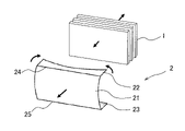
- FIG. 1A is a perspective view of a battery module according to a first embodiment of the present invention
- FIG. 1B is an exploded perspective view of the battery module shown in FIG. 1A
- FIG. 1C is a perspective view of the battery inside the battery module.
- the battery module 100 in this embodiment, three plate-shaped batteries 1 are stacked and fixed inside a housing 3 composed of two cover members 2. It is The two cover members 2 are connected and fixed by a connecting member (not shown), and the battery 1 is press-fitted into the housing 3 in the stacking direction.
- the battery module 100 may be arranged, for example, in a battery housing room of a vehicle, or may be mounted outside the vehicle.
- the battery 1 is a chargeable/dischargeable storage battery configured in the shape of a rectangular parallelepiped plate.
- the battery 1, which is a plate-like member includes plate surface portions facing each other in the stacking direction, and four side surface portions provided perpendicular to the plate surface portion.
- the side portion on the upper side of the drawing is called an upper side portion
- the side portion on the lower side of the drawing is called a lower side portion.
- the surface facing and contacting the cover member 2 on the outer side in the stacking direction is referred to as a stacking end surface 11 .
- the battery 1 is fixed inside the housing 3 with the plate surface portion of the battery 1 sandwiched between the flat portions 21 of the pair of cover members 2 .
- the plate surface portion of the battery 1 and the flat surface portion 21 of the cover member 2 are electrically insulated.
- the side surface of the battery 1 is separated from the upper side surface portion 22 and the lower side surface portion 23 of the cover member 2 .
- the battery 1 is, for example, a lithium ion battery and has an electrolyte inside.
- the battery 1 may swell and increase in thickness. As shown in FIG. 1C, each battery 1 expands so as to become thicker around the center of the stacking surface (the arrow portion in the drawing).
- the cover member 2 constituting the housing 3 includes a flat portion 21 that contacts the stacking end surface 11 of the battery 1, an upper side portion 22 that is connected to the flat portion 21 in the vertical direction of the drawing, and a and a lower side portion 23 .
- the plane portion 21 is formed in a rectangular shape whose width direction is longer than its height direction.
- the plane portion 21 and the upper side portion 22 are connected via the upper side 24
- the plane portion 21 and the lower side portion 23 are connected via the lower side 25 .
- the upper side 24 and the lower side 25 are examples of the first side.
- long sides 26 facing and substantially parallel to the upper side 24 of the upper side surface portion 22 and long sides 27 facing and substantially parallel to the lower side 25 of the lower side surface portion 23 extend in the stacking direction near the center.
- a cutout 28 is provided.
- the notch 28 is tapered such that the width of the notch 28 narrows inward (upper side 24 and lower side 25 ) from the long sides 26 and 27 in the upper side surface portion 22 and the lower side surface portion 23 .
- the long sides 26 and 27 are examples of the second side.
- the cover members 2 form a set to form a housing 3 .
- the pair of cover members 2 are arranged such that the upper side surface portion 22 and the lower side surface portion 23 extend inward from each other with the flat portions 21 facing each other. In this manner, the housing 3 that accommodates the battery 1 in a region defined by the plane portion 21 and the upper side surface portion 22 and the lower side surface portion 23 is configured.
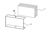
- FIGS. 2A and 2B are part of an exploded perspective view of a battery module 100 of a comparative example, showing a battery 1 and one cover member 2 provided on the left front side of the battery 1 in the figure. Therefore, the description of the other cover member 2 at the back right of the drawing is omitted.
- the cutout 28 is not provided in the cover member 2 .
- 2A shows the state of the battery 1 before expansion
- FIG. 2B shows the state of the battery 1 after expansion.
- the plane portion 21 and the upper side portion 22 are connected via the upper side 24
- the plane portion 21 and the lower side portion 23 are connected via the lower side 25 . Therefore, due to the stress acting outward in the stacking direction at the central portions of the upper side 24 and the lower side 25, both longitudinal ends of the upper side portion 22 and the lower side portion 23 approach each other as indicated by the arrows. Inwardly directed stress occurs.
- FIGS. 3A and 3B are exploded perspective views of the battery module 100 of this embodiment. These figures also show the battery 1 and one cover member 2 provided on the front left side of the battery 1, and the illustration of the other cover member 2 on the back right side of the figure is omitted. 3A shows the state of the battery 1 before expansion, and FIG. 3B shows the state of the battery 1 after expansion. As shown in these figures, the cover member 2 is provided with a notch 28 .
- a stress line 29 extending in the lateral direction is shown in the longitudinal central portion of the plane portion 21 .
- a stress line 29 indicates a portion of the planar portion 21 where stress acting outward due to the expansion of the battery 1 is likely to act.
- the cutouts 28 provided in the upper side surface portion 22 and the lower side surface portion 23 are provided so as to extend in the same plane as the stress line 29 .
- the cutouts 28 are provided so that even if stress acts inwardly at both end portions as indicated by the arrows, the upper side surface portion 22 and the lower side surface portion 23 are The lower side surface portion 23 is deformed so that the width of the notch 28 is narrowed. As a result, compared to the case where the notch 28 as shown in FIG. 2B is not provided, the upper side surface portion 22 and the lower side surface portion 23 are prevented from sagging in the facing direction (inward of the cover member 2). be done.
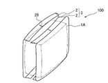
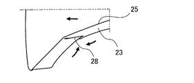
- FIG. 4A to 4C are perspective views of the battery module 100 when the battery 1 is inflated, viewed from other directions.
- FIG. 4A is an overall perspective view of the battery module 100.
- FIG. 4B is a perspective view of one side of the cover member 2 as seen from the inside.
- 4C is an enlarged view of the lower side portion 23 of the cover member 2.
- FIG. 4A a state in which a plurality of batteries 1 are stacked is collectively shown as a battery stack 1A.
- notches 28 are provided in the side portions 22 and 23 . Therefore, even if a stress acts inward on the side portions 22 and 23, the groove width of the notch 28 of the side portions 22 and 23 becomes narrower, and the opposing inner side surfaces of the side portions 22 and 23 move closer to each other. In this figure, the notch 28 has no groove width and is deformed to such an extent that the opposing inner side surfaces of the notch 28 overlap each other. As a result, sagging (curving) toward the facing direction (the inner side of cover member 2 ) of side portions 22 and 23 is suppressed, and the risk of contact between cover member 2 and the side surface of battery 1 can be reduced.
- the contact between the cover member 2 and the side surface of the battery 1 can be detected by using a technique for monitoring the insulation of the battery module 100 . Since the cover member 2 is prevented from coming into contact with the battery 1 by providing the notch 28 as in the present embodiment, it takes a longer time to detect that there is a problem with the insulation. The inspection cycle can be lengthened. On the other hand, by shortening the notch 28, the suppression amount of the depression (bending) toward the inside of the cover member 2 in the direction in which the side portions 22 and 23 face each other becomes small, so that it is detected that there is a problem with the insulation. The time until the battery 1 is shortened, and the periodical inspection of the battery 1 can be shortened to promote regular inspection. Thus, the size and shape of the notch 28 may be changed according to the target inspection period of the battery 1 (the target time until it is detected that there is a problem with the insulation).
- a laminated battery stack 1 ⁇ /b>A may be formed and housed in the housing 3 .
- the laminated battery stack 1A when it expands due to deterioration over time, the thickness in the vertical direction increases with respect to the portion having a large area (plate surface portion). Therefore, by having a notch 28 in the side surface portions 22 and 23 connected to the flat surface portion 21 facing the surface corresponding to the stacking end surface 11 having a large area, the inside of the side surface portions 22 and 23 due to the expansion of the battery 1 can be suppressed.
- the battery module 100 of the first embodiment has a plate-shaped battery 1 and a cover member 2 (housing 3) that houses the battery 1 inside.
- the cover member 2 faces a flat portion 21 that sandwiches the stack end surface 11 (plate surface portion) of the battery 1 while being spaced apart from the side surface of the battery 1, and covers the flat portion 21 with an upper side 24 and a lower side 25 (first side). It has side parts 22 and 23 connected via. Further, the side surface portions 22 and 23 of the cover member 2 are arranged such that the upper side 24 and the lower side 25 ( It has a notch 28 which is a curve regulating structure extending toward the first side).
- the notches 28 are provided, so that outward stress acts on the central portion of the upper side 24 and the lower side 25 and inward stress acts on both end portions.
- the upper side surface portion 22 and the lower side surface portion 23 are deformed so that the width of the notch 28 is narrowed.
- inward sagging (bending) of the cover member 2 near the center of the upper side surface portion 22 and the lower side surface portion 23 is suppressed, and the risk of the cover member 2 coming into contact with the battery 1 can be reduced.
- the cutouts 28 are provided in the upper side surface portion 22 and the lower side surface portion 23 , it is not possible to completely prevent the cover member 2 from sagging inward.
- the maximum value of the inward depression amount (deflection amount) of these deflections is the deflection when the notch 28 is not provided in the upper side surface portion 22 and the lower side surface portion 23 and the deflection occurs at one place. less than quantity. Since the amount of deflection is reduced by providing the notch 28 in this way, contact between the cover member 2 and the battery 1 is suppressed.
- the notch 28, which is the curving regulation structure, is tapered such that the width becomes narrower from the long sides 26 and 27 toward the inside of the plane (upper side 24 and lower side 25). It is That is, the notch 28 is formed in the long sides 26 and 27 of the upper side surface portion 22 and the lower side surface portion 23, which are farthest from the upper side 24 and the lower side 25 contacting the flat portion 21 on which the stress due to the expanding battery 1 acts. It is configured such that the groove width is widened.
- the depression (curvature) of the upper side surface portion 22 and the lower side surface portion 23 in the facing direction increases as the distance from the upper side 24 and the lower side 25 connected to the flat portion 21 increases. Therefore, the notch 28 is configured so that the long sides 26 and 27 that are farthest from the plane portion 21 are wide. As a result, the cutouts 28 for restricting the curvature are formed to be wide at the locations where the upper side surface portion 22 and the lower side surface portion 23 are likely to sag more toward the inside of the cover member 2 . It is possible to reduce the amount of deflection caused by the inward depression of the lower side surface portion 23 .
- one notch 28 is provided near the center of the long side 26 of the upper side surface portion 22 and the long side 27 of the lower side surface portion 23 .
- the cover member 2 when the central portion of the planar portion 21 is pushed outward and stress is concentrated near the center of the upper side 24 and the lower side 25, the upper side portion 22 and the lower side portion 25 are bent outward. Inwardly directed stress acts on both end portions of 23 .
- FIG. 5 is a perspective view showing the battery system 200 of the second embodiment.
- a battery system 200 is configured by arranging a plurality of battery modules 100 of the first embodiment (four battery modules 100A to 100D in this embodiment) side by side in the stacking direction of the battery 1. ing.
- notches are provided in the upper side surface portion 22 and the lower side surface portion 23 of the cover member 2 positioned outside in the side-by-side direction. 28 are provided (the notch 28 of the lower side surface portion 23 is not shown).
- the outer cover member 2 of the battery modules 100A and 100D located outside the side-by-side direction has a large amount of displacement in the thickness direction. Become. Therefore, by providing the notch 28 in the upper side surface portion 22 and the lower side surface portion 23 of the outer cover member 2 for each of the battery modules 100A and 100D, the influence of the cover member 2 having a large amount of displacement in the thickness direction is increased. Inward depression of the side surface portion 22 and the lower side surface portion 23 is suppressed.
- the notches 28 are provided in the side portions 22 and 23 of the cover member 2 located on the outer side.
- the curvature of the flat portion 21 of the cover member 2 due to the expansion of the battery 1 in the side-by-side arrangement direction is the same as the outermost cover member of the battery modules 100A and 100D located on the outermost side in the side-by-side direction. 2, the amount of displacement increases. Therefore, in each of the outermost battery modules 100A and 100D, by providing the notch 28 in the upper side surface portion 22 and the lower side surface portion 23 of the outer cover member 2, the upper side of the cover member 2 having a larger displacement amount The sagging of the side surface portion 22 and the lower side surface portion 23 toward the inside of the cover member 2 is suppressed. As a result, it is possible to suppress sagging (bending) of the upper side surface portion 22 and the lower side surface portion 23 in the facing directions while reducing the locations where the cutouts 28 are provided.
- FIG. 6 is a perspective view of the battery system 200 of the third embodiment.
- the cover member 2 closer to the outside in the side-by-side arrangement direction has a notch 28. is provided. That is, in the battery modules 100A and 100B, the notch 28 is provided in the cover member 2 located on the right rear side in the figure, and in the battery modules 100C and 100D, the notch 28 is provided in the cover member 2 located on the left front side in the figure. be provided.
- two cutouts 28 are provided in the upper side surface portion 22 and the lower side surface portion 23 of the cover member 2 . These two cutouts 28 are provided symmetrically with respect to the longitudinal center line of the upper side portion 22 and the lower side portion 23 . Even if the notch 28 is formed in this way, the upper side surface portion 22 and the lower side surface portion 23 are prevented from sagging (curving) toward the inside of the cover member 2 in the vicinity of the center. 1 can be reduced.
- the notch 28 is provided in the side surface portion 22 of the cover member 2 located near the outside. That is, in the battery modules 100A and 100B, the notch 28 is provided in the cover member 2 located on the right rear side in the figure, and in the battery modules 100C and 100D, the notch 28 is provided in the cover member 2 located on the left front side in the figure. be provided.
- the curvature of the cover member 2 due to the expansion of the battery modules 100A to 100D has a larger amount of displacement in the thickness direction when positioned further outside in the side-by-side arrangement direction. Therefore, in each of the battery modules 100A to 100D, a notch 28 is provided in the upper side surface portion 22 and the lower side surface portion 23 of the cover member 2 closer to the outside. This suppresses deformation of the upper side surface portion 22 and the lower side surface portion 23 of the cover member 2 having a large amount of displacement in the facing directions, thereby suppressing the contact of the cover member 2 with the battery 1 .
- a plurality (two) of notches 28 are provided on each of the long sides 26 and 27 in pairs symmetrically with respect to the center line in the longitudinal direction.
- the cutouts 28 are provided in the side portions 22 and 23 , it is not possible to completely prevent the cover member 2 from sagging inward.
- the side portions 22 and 23 of the present embodiment three portions facing each other in the longitudinal direction via two cutouts 28 are bent due to depression.
- the maximum amount of depression (amount of bending) in the depth direction (inner side) of these bendings is at the upper side portion 22 and the lower side portion 23.
- FIG. 7 is a perspective view of the battery module 100 according to the fourth embodiment.
- a first notch 28A provided near the center and two notches symmetrical in the longitudinal direction with respect to the first notch 28A.
- a second notch 28B is provided.
- both the first notch 28A and the second notch 28B are provided in a tapered shape, and the depth in the transverse direction of the first notch 28A is greater than that of the second notch 28B. long. Even if the notch 28 is formed in this way, the upper side surface portion 22 and the lower side surface portion 23 are prevented from sagging (curving) toward the inside of the cover member 2 in the vicinity of the center. 1 can be reduced.
- the battery module 100 of the fourth embodiment by providing a plurality of cutouts 28, it is possible to reduce the deflection amount of the upper side surface portion 22 and the lower side surface portion 23 as a whole. Furthermore, the depth in the lateral direction is longer in the first notch 28A provided in the central portion in the longitudinal direction than in the second notch 28B provided on the side of the first notch 28A. In this manner, the first notch 28A provided in the portion of the upper side surface portion 22 and the lower side surface portion 23 where the stress caused by the expansion of the battery 1 is likely to act is made longer. The drop in the portion 23 can be reduced.
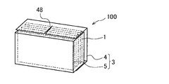
- FIG. 8A is a perspective view of the battery module according to the fourth embodiment.
- 8B is an exploded perspective view of the battery module shown in FIG. 8A.
- the housing 3 of the fifth embodiment is composed of cover members 4 and 5, which are connected by welding.
- the cover member 4 includes a flat surface 41 and an upper side surface portion 42 and a lower side surface portion 43 that are connected to the flat surface 41 at an upper side 44 and a lower side 45 .
- a notch 48 is provided near the center in the longitudinal direction on long sides 46 and 47 facing the upper side 44 and the lower side 45 .
- the cover member 5 includes a plane 51, and a right side portion 52 and a left side portion 53 connected to the right side and left side of the plane 51, respectively. No notches are provided on the right side surface portion 52 and the left side surface portion 53 of the cover member 5 .
- the cover member 4 and the cover member 5 are arranged so that the flat surfaces 41 and 51 face each other, and the upper side surface portion 42 and the lower side surface portion 43 and the right side surface portion 52 and the left side surface portion 53 are fitted to each other.
- the housing 3 is configured by the cover member 4 and the cover member 5 .
- the outward stress is concentrated near the center in the longitudinal direction and curved. Due to this curvature, in the upper side surface portion 42 and the lower side surface portion 43, stress acts inward at both ends in the longitudinal direction. Since the cutouts 48 are provided in the upper side surface portion 42 and the lower side surface portion 43 , the upper side surface portion 42 and the lower side surface portion 43 do not exceed the width of the cutouts 48 even if stress acts inward at both end portions. is deformed to become narrower. As a result, the upper side surface portion 42 and the lower side surface portion 43 are prevented from sagging (curving) toward the inside of the cover member 4 .
- the battery module 100 of the fifth embodiment has a plate-shaped battery 1 and a cover member 4 (housing 3) that accommodates the battery 1 inside.
- the cover member 4 includes a flat surface 41 facing the stack end surface 11 (plate surface portion) of the battery 1 and side surface portions 42 and 43 facing the side surface of the battery 1 and connected to the flat surface 41 .
- the side portions 42 and 43 of the cover member 4 have cutouts 48 which are curving restricting structures in the long sides 46 and 47 facing the upper side 44 and the lower side 45 connected to the flat surface 41 .
- the cutouts 48 are provided so that the upper side surface portion 42 and the lower side surface portion 43 are not cut even if stress acts inward on both side portions.
- the opposing inner surfaces of the notch 48 are deformed to become closer and narrower.
- the upper side surface portion 42 and the lower side surface portion 43 are prevented from sagging toward the inside of the cover member 4 in the vicinity of the center, and the risk of the cover member 4 coming into contact with the battery 1 can be reduced.
- the cutouts 28 and 48 are provided in the cover members 2 and 4 that constitute the battery module 100, so that when the battery 1 accommodated inside expands, the notches 28 and 48 are provided. , the cover members 2 and 4 are prevented from falling inward.
- the sixth embodiment an example in which a curve regulating structure having a shape different from that of the cutouts 28 and 48 is provided will be described.
- the housing 3 is constructed by facing the cover members 2 having the same shape as in the first embodiment.
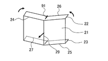
- FIG. 9A and 9B are exploded perspective views of the battery module 100 when the battery 1 is expanded in this embodiment.
- FIG. 9A is a perspective view of one of the cover members 2 as seen from the inside.
- 9B is an enlarged view of the lower side portion of the cover member 2.
- the side portions 22 and 23 are provided with protrusions 91 instead of the cutouts 28 .
- the projecting portion 91 is provided near the center of the long sides 26 and 27 so as to extend toward the upper side 24 and the lower side 25 .
- the projecting portion 91 extends from the side portions 22 and 23 in a tapered region in which the width of the side portions 22 and 23 narrows from the long sides 26 and 27 toward the inner side (upper side 24 and lower side 25). configured to protrude.
- the protruding portion 91 is a play (slack) protruding from the side portions 22 and 23 and may be folded.
- the protrusions 91 are provided, so that when a stress acts inwardly at both end portions as indicated by the arrows, the protrusions 91 move toward the upper side surface portion. 22 and the lower side portion 23 are deformed so as to protrude further in the direction opposite to the side facing the lower side portion 23 . As a result, the upper side surface portion 22 and the lower side surface portion 23 are prevented from falling toward the inside of the cover member 2 along the stress line 29 .
- the side portions 22 and 23 do not move toward both ends of the projecting portion 91 even if stress acts inward on both sides.
- the portions are brought closer to each other and deformed so that the width becomes narrower, and deformed so as to protrude further with respect to the side portions 22 and 23.
- - ⁇ As a result the upper side surface portion 22 and the lower side surface portion 23 do not drop toward the inside of the cover member 2 in the vicinity of the center, thereby reducing the risk of the cover member 2 coming into contact with the battery 1 .
- tapered notches 28 are provided in the side portions 22 and 23 so that the width becomes narrower from the long sides 26 and 27 toward the upper side 24 and the lower side 25.
- tapered cutouts 48 are provided in the side portions 42 and 43 such that the width narrows from the long sides 46 and 47 toward the upper side 44 and the lower side 45.
- the side portions Although the protruding portions 81 are provided at 22 and 23 such that the width is narrowed from the long sides 26 and 27 toward the upper side 24 and the lower side 25, the present invention is not limited to this. Even if the cutouts 28 and 48 and the projecting portion 81 are provided with the same width, it is possible to prevent the side portions 22 , 23 , 42 , 43 , 52 , and 53 from sagging (curving) inward.
- the cover member 2 is not provided with lateral side portions in the horizontal direction of the figure, but is provided with the upper side portion 22 and the lower side portion 23. It is not limited to this. Side portions may be provided on the cover member 2 in the horizontal direction of the drawing. In such a case, curving restricting members such as cutouts or protrusions may be provided on the left and right side portions of these figures. It is possible to suppress the fall (bending) into the In addition, in the fifth embodiment, the right side surface portion 52 and the left side surface portion 53 of the cover member 5 are not provided with notches. ) can be suppressed.
Landscapes
- Chemical & Material Sciences (AREA)
- Chemical Kinetics & Catalysis (AREA)
- Electrochemistry (AREA)
- General Chemical & Material Sciences (AREA)
- Battery Mounting, Suspending (AREA)
Abstract
Description
図1Aは、本発明の第1実施形態に係るバッテリモジュールの斜視図である。図1Bは、図1Aに示されたバッテリモジュールの分解斜視図である。図1Cは、バッテリモジュール内部のバッテリの斜視図である。 (First embodiment)
1A is a perspective view of a battery module according to a first embodiment of the present invention; FIG. FIG. 1B is an exploded perspective view of the battery module shown in FIG. 1A. FIG. 1C is a perspective view of the battery inside the battery module.
第1実施形態においては、1つのバッテリモジュール100が配置される例について説明したが、これに限らない。第2実施形態においては、バッテリモジュール100の複数が、バッテリ1の積層方向に向かって積層される例について説明する。 (Second embodiment)
Although the example in which one
第3実施形態においては、第2実施形態と同様のバッテリシステム200における、他の切り欠き28の構成例について説明する。 (Third embodiment)
In the third embodiment, another configuration example of the
第4実施形態においては、バッテリモジュール100の切り欠き28の他の構成例について説明する。 (Fourth embodiment)
In the fourth embodiment, another configuration example of the
第1~第4実施形態においては、バッテリモジュール100は、同じ形状のカバー部材2が対向してカバー部材2が構成される例について説明したが、これに限らない。第4実施形態においては、異なる形状のカバー部材2が互いに嵌り合うように組み合わされてカバー部材2が構成される例について説明する。 (Fifth embodiment)
In the first to fourth embodiments, an example in which the
第1~第5実施形態においては、バッテリモジュール100を構成するカバー部材2、4において湾曲規制構造としての切り欠き28、48が設けられることにより、内部に収容されたバッテリ1が膨張した場合に、カバー部材2、4が内側に向かって落ち込むのが抑制される例について説明した。第6実施形態においては、切り欠き28、48とは異なる形状の湾曲規制構造を備える例について説明する。なお、本実施形態においては、第1実施形態と同様に同じ形状のカバー部材2が対向して筐体3が構成されている。 (Sixth embodiment)
In the first to fifth embodiments, the
Claims (9)
- 板状のバッテリと、前記バッテリを内部に収容するケースと、を有するバッテリモジュールであって、
前記ケースは、前記バッテリの板面部を挟持する平面部と、前記バッテリの側面と対向し、前記平面部と第1辺を介して接続される側面部とを備え、
前記ケースの前記側面部は、前記第1辺と対向する第2辺から前記第1辺に向かって延在する湾曲規制構造を有する、バッテリモジュール。 A battery module having a plate-shaped battery and a case for housing the battery therein,
The case includes a flat portion that sandwiches the plate surface portion of the battery, and a side surface portion that faces the side surface of the battery and is connected to the flat portion via a first side,
The battery module, wherein the side portion of the case has a curving restriction structure extending from a second side facing the first side toward the first side. - 請求項1に記載のバッテリモジュールであって、
前記湾曲規制構造は、前記側面部の前記第2辺から前記第1辺に向かって設けられる切り欠きである、バッテリモジュール。 The battery module according to claim 1,
In the battery module, the curving regulating structure is a notch provided from the second side of the side surface toward the first side. - 請求項2に記載のバッテリモジュールであって、
前記切り欠きは、前記第2辺から前記第1辺に向かって幅が狭くなるように構成される、バッテリモジュール。 The battery module according to claim 2,
The battery module, wherein the notch is configured such that the width of the notch narrows from the second side toward the first side. - 請求項1に記載のバッテリモジュールであって、
前記湾曲規制構造は、前記側面部から突出する突出部である、バッテリモジュール。 The battery module according to claim 1,
The battery module, wherein the curving regulating structure is a projecting portion projecting from the side surface portion. - 請求項1から4のいずれか1項に記載のバッテリモジュールであって、
前記湾曲規制構造は、前記側面部において前記第2辺の中央近傍に1つ設けられる、バッテリモジュール。 The battery module according to any one of claims 1 to 4,
The battery module, wherein the bending regulating structure is provided near the center of the second side on the side surface portion. - 請求項1から4のいずれか1項に記載のバッテリモジュールであって、
前記湾曲規制構造は、前記側面部において前記第2辺の中央部を中心に略対称に組をなして設けられる、バッテリモジュール。 The battery module according to any one of claims 1 to 4,
In the battery module, the curving regulating structures are provided in a set substantially symmetrically about a central portion of the second side on the side portion. - 請求項3に記載のバッテリモジュールであって、
前記切り欠きは、前記側面部において前記第2辺の中央近傍に1つ設けられる第1切り欠きと、前記第1切り欠きに対して略対称に組をなして設けられる第2切り欠きと、を含み、
前記第1切り欠きは、前記第2切り欠きよりも、前記第2辺から前記第1辺に向かう方向に長くなるように構成されている、バッテリモジュール。 The battery module according to claim 3,
The notches include a first notch provided near the center of the second side in the side surface portion, and a second notch provided in a pair substantially symmetrically with respect to the first notch; including
The battery module, wherein the first notch is longer than the second notch in a direction from the second side toward the first side. - 請求項1から7のいずれか1項に記載のバッテリモジュールが複数積層されることによって構成されるバッテリシステムであって、
前記バッテリモジュールにおいて、外側に対して近い位置にある前記ケースの前記側面部が前記湾曲規制構造を有する、バッテリシステム。 A battery system configured by stacking a plurality of battery modules according to any one of claims 1 to 7,
The battery system of the battery module, wherein the side portion of the case located near the outside has the curving restriction structure. - 請求項8に記載のバッテリシステムにおいて、
前記バッテリシステムの積層方向の最も外側に位置する前記バッテリモジュールにおいて、外側に対して近い位置にある前記ケースの前記側面部が前記湾曲規制構造を有する、バッテリシステム。 In the battery system according to claim 8,
A battery system according to claim 1, wherein, in the battery module positioned on the outermost side in the stacking direction of the battery system, the side surface portion of the case positioned close to the outside has the curving restriction structure.
Priority Applications (5)
| Application Number | Priority Date | Filing Date | Title |
|---|---|---|---|
| US18/287,432 US20240204323A1 (en) | 2021-04-23 | 2021-04-23 | Battery Module and Battery System |
| JP2023516020A JPWO2022224461A1 (en) | 2021-04-23 | 2021-04-23 | |
| EP21937214.1A EP4329063A4 (en) | 2021-04-23 | 2021-04-23 | Battery module and battery system |
| CN202180097321.6A CN117256069A (en) | 2021-04-23 | 2021-04-23 | Battery pack and battery system |
| PCT/JP2021/016550 WO2022224461A1 (en) | 2021-04-23 | 2021-04-23 | Battery module and battery system |
Applications Claiming Priority (1)
| Application Number | Priority Date | Filing Date | Title |
|---|---|---|---|
| PCT/JP2021/016550 WO2022224461A1 (en) | 2021-04-23 | 2021-04-23 | Battery module and battery system |
Publications (1)
| Publication Number | Publication Date |
|---|---|
| WO2022224461A1 true WO2022224461A1 (en) | 2022-10-27 |
Family
ID=83722184
Family Applications (1)
| Application Number | Title | Priority Date | Filing Date |
|---|---|---|---|
| PCT/JP2021/016550 WO2022224461A1 (en) | 2021-04-23 | 2021-04-23 | Battery module and battery system |
Country Status (5)
| Country | Link |
|---|---|
| US (1) | US20240204323A1 (en) |
| EP (1) | EP4329063A4 (en) |
| JP (1) | JPWO2022224461A1 (en) |
| CN (1) | CN117256069A (en) |
| WO (1) | WO2022224461A1 (en) |
Citations (7)
| Publication number | Priority date | Publication date | Assignee | Title |
|---|---|---|---|---|
| JP2002264582A (en) | 2001-03-13 | 2002-09-18 | Fumiko Dairakuin | Whiteboard marker set in whiteboard eraser with magnet |
| JP2014179298A (en) * | 2013-03-15 | 2014-09-25 | Gs Yuasa Corp | Power supply module |
| WO2017026145A1 (en) * | 2015-08-07 | 2017-02-16 | 株式会社Ihi | Cell module |
| US20180047954A1 (en) * | 2015-06-16 | 2018-02-15 | Lg Chem, Ltd. | Cell cover for secondary battery, and battery module comprising same |
| KR20180068379A (en) * | 2016-12-13 | 2018-06-22 | 현대자동차주식회사 | Battery case of electric vehicle |
| JP2019114477A (en) * | 2017-12-25 | 2019-07-11 | トヨタ自動車株式会社 | Battery module |
| KR20200033666A (en) * | 2018-09-20 | 2020-03-30 | 주식회사 엘지화학 | Battery module, battery pack comprising the battery module, and vehicle comprising the battery pack |
Family Cites Families (2)
| Publication number | Priority date | Publication date | Assignee | Title |
|---|---|---|---|---|
| DE202013003672U1 (en) * | 2013-04-10 | 2014-07-11 | Reinz-Dichtungs-Gmbh | cell stack |
| JP6960271B2 (en) * | 2017-08-10 | 2021-11-05 | 日立造船株式会社 | All solid state battery |
-
2021
- 2021-04-23 EP EP21937214.1A patent/EP4329063A4/en active Pending
- 2021-04-23 JP JP2023516020A patent/JPWO2022224461A1/ja active Pending
- 2021-04-23 WO PCT/JP2021/016550 patent/WO2022224461A1/en active Application Filing
- 2021-04-23 US US18/287,432 patent/US20240204323A1/en active Pending
- 2021-04-23 CN CN202180097321.6A patent/CN117256069A/en active Pending
Patent Citations (7)
| Publication number | Priority date | Publication date | Assignee | Title |
|---|---|---|---|---|
| JP2002264582A (en) | 2001-03-13 | 2002-09-18 | Fumiko Dairakuin | Whiteboard marker set in whiteboard eraser with magnet |
| JP2014179298A (en) * | 2013-03-15 | 2014-09-25 | Gs Yuasa Corp | Power supply module |
| US20180047954A1 (en) * | 2015-06-16 | 2018-02-15 | Lg Chem, Ltd. | Cell cover for secondary battery, and battery module comprising same |
| WO2017026145A1 (en) * | 2015-08-07 | 2017-02-16 | 株式会社Ihi | Cell module |
| KR20180068379A (en) * | 2016-12-13 | 2018-06-22 | 현대자동차주식회사 | Battery case of electric vehicle |
| JP2019114477A (en) * | 2017-12-25 | 2019-07-11 | トヨタ自動車株式会社 | Battery module |
| KR20200033666A (en) * | 2018-09-20 | 2020-03-30 | 주식회사 엘지화학 | Battery module, battery pack comprising the battery module, and vehicle comprising the battery pack |
Non-Patent Citations (1)
| Title |
|---|
| See also references of EP4329063A4 |
Also Published As
| Publication number | Publication date |
|---|---|
| US20240204323A1 (en) | 2024-06-20 |
| EP4329063A1 (en) | 2024-02-28 |
| JPWO2022224461A1 (en) | 2022-10-27 |
| EP4329063A4 (en) | 2024-07-03 |
| CN117256069A (en) | 2023-12-19 |
Similar Documents
| Publication | Publication Date | Title |
|---|---|---|
| JP7174923B2 (en) | power storage device | |
| US9450219B2 (en) | Battery module | |
| US20120189899A1 (en) | Secondary battery, secondary battery manufacturing device, and secondary battery manufacturing method | |
| JP7024735B2 (en) | Power storage device | |
| US11223084B2 (en) | Energy storage apparatus | |
| JP2017098107A (en) | Power storage device | |
| JP6426779B2 (en) | Battery module | |
| JP2013109858A (en) | Battery | |
| JP7557527B2 (en) | Battery Module | |
| WO2016157919A1 (en) | Battery pack | |
| US20160276713A1 (en) | Laminated secondary battery | |
| WO2022224461A1 (en) | Battery module and battery system | |
| JP7307069B2 (en) | Fixing structure of battery module | |
| JP2018026244A (en) | Battery module | |
| WO2018159266A1 (en) | Power storage apparatus and method for manufacturing power storage apparatus | |
| JP2017117633A (en) | Method of manufacturing battery pack | |
| US11557809B2 (en) | Battery pack | |
| JP2014049303A (en) | Power storage device | |
| US20240234915A9 (en) | Battery module | |
| JP7544497B2 (en) | Battery pack | |
| JP7116893B2 (en) | assembled battery | |
| JP2024004956A (en) | Battery module and spacer | |
| EP4358250A1 (en) | Battery module | |
| JP2023178050A (en) | Battery module and spacer | |
| JP7154027B2 (en) | Method for manufacturing power storage device |
Legal Events
| Date | Code | Title | Description |
|---|---|---|---|
| 121 | Ep: the epo has been informed by wipo that ep was designated in this application |
Ref document number: 21937214 Country of ref document: EP Kind code of ref document: A1 |
|
| WWE | Wipo information: entry into national phase |
Ref document number: 2023516020 Country of ref document: JP |
|
| WWE | Wipo information: entry into national phase |
Ref document number: 18287432 Country of ref document: US |
|
| WWE | Wipo information: entry into national phase |
Ref document number: 202180097321.6 Country of ref document: CN |
|
| WWE | Wipo information: entry into national phase |
Ref document number: 2021937214 Country of ref document: EP |
|
| NENP | Non-entry into the national phase |
Ref country code: DE |
|
| ENP | Entry into the national phase |
Ref document number: 2021937214 Country of ref document: EP Effective date: 20231123 |