WO2022224328A1 - 操作入力装置、情報処理装置および操作入力方法 - Google Patents
操作入力装置、情報処理装置および操作入力方法 Download PDFInfo
- Publication number
- WO2022224328A1 WO2022224328A1 PCT/JP2021/015938 JP2021015938W WO2022224328A1 WO 2022224328 A1 WO2022224328 A1 WO 2022224328A1 JP 2021015938 W JP2021015938 W JP 2021015938W WO 2022224328 A1 WO2022224328 A1 WO 2022224328A1
- Authority
- WO
- WIPO (PCT)
- Prior art keywords
- operation knob
- knob
- display
- information
- bending
- Prior art date
- Legal status (The legal status is an assumption and is not a legal conclusion. Google has not performed a legal analysis and makes no representation as to the accuracy of the status listed.)
- Ceased
Links
Images











Classifications
-
- G—PHYSICS
- G06—COMPUTING OR CALCULATING; COUNTING
- G06F—ELECTRIC DIGITAL DATA PROCESSING
- G06F3/00—Input arrangements for transferring data to be processed into a form capable of being handled by the computer; Output arrangements for transferring data from processing unit to output unit, e.g. interface arrangements
- G06F3/01—Input arrangements or combined input and output arrangements for interaction between user and computer
- G06F3/03—Arrangements for converting the position or the displacement of a member into a coded form
- G06F3/033—Pointing devices displaced or positioned by the user, e.g. mice, trackballs, pens or joysticks; Accessories therefor
- G06F3/0362—Pointing devices displaced or positioned by the user, e.g. mice, trackballs, pens or joysticks; Accessories therefor with detection of one-dimensional [1D] translations or rotations of an operating part of the device, e.g. scroll wheels, sliders, knobs, rollers or belts
-
- G—PHYSICS
- G06—COMPUTING OR CALCULATING; COUNTING
- G06F—ELECTRIC DIGITAL DATA PROCESSING
- G06F3/00—Input arrangements for transferring data to be processed into a form capable of being handled by the computer; Output arrangements for transferring data from processing unit to output unit, e.g. interface arrangements
- G06F3/01—Input arrangements or combined input and output arrangements for interaction between user and computer
- G06F3/03—Arrangements for converting the position or the displacement of a member into a coded form
- G06F3/041—Digitisers, e.g. for touch screens or touch pads, characterised by the transducing means
Definitions
- the present disclosure relates to an operation input device, an information processing device, and an operation input method.
- Patent Literature 1 describes an operation input device that includes an operator, which is a dial switch or a rotary switch, and a finger sensor that detects the number of fingers holding the operator.
- the operation input device identifies the number of fingers gripping the operator based on the detection result of the finger sensor, and switches the operation command for the operation input according to the number of fingers gripping the operator.
- the operation input device described in Patent Document 1 has the problem of poor operability because it is necessary to change the number of fingers that hold the operator when switching to another operation. For example, even if the manipulator is easier to rotate with a larger number of fingers, it may be necessary to unnaturally rotate the manipulator with a smaller number of fingers depending on the function to be executed. Further, if the finger touches the manipulator while rotating the manipulator, a function different from the function to be executed may be erroneously executed.
- the present disclosure is intended to solve the above problems, and provides an operation input device, an information processing device, and an operation input method that enable an operation corresponding to a desired function to be performed regardless of the number of fingers that hold the operator. for the purpose.
- An operation input device includes an operation knob provided rotatably on a touch surface of a touch panel and an operation element having a detection unit that detects an operation of grasping and bending the operation knob, and an operation element.
- an operation information generation unit that generates operation information indicating an operation and outputs the operation information to a function execution unit that executes a function corresponding to the operation, the operation information generation unit bending the operation knob detected by the detection unit; Generates operation information indicating the operation to be performed.
- an operator having an operation knob and a detection unit, an operation information generator that generates operation information indicating an operation using the operator, and outputs the operation information to a function execution unit, the operation information
- the generation unit generates operation information indicating an operation to bend the operation knob detected by the detection unit. Since the function to be executed can be specified by a natural operation of bending the operation knob by changing the gripping force, the operation input device according to the present disclosure can perform the desired function regardless of the number of fingers gripping the operation element. Corresponding operations can be performed.
- FIG. 1 is a block diagram showing a configuration example of an information processing apparatus according to Embodiment 1;
- FIG. FIG. 2A is a perspective view showing the manipulator, and
- FIG. 2B is a configuration diagram showing the internal configuration of the manipulator.
- FIG. 3A is a configuration diagram showing the internal configuration of the manipulator before an operation to bend the operation knob by holding it, and
- 5A is a block diagram showing a hardware configuration that implements the functions of the operation input device according to Embodiment 1, and
- FIG. 5B shows a hardware configuration that implements the functions of the operation input device according to Embodiment 1.
- FIG. 1 is a block diagram showing a configuration example of an information processing apparatus according to Embodiment 1;
- FIG. FIG. 2A is a perspective view showing the manipulator, and
- FIG. 2B is a configuration diagram showing the
- FIG. 3 is a block diagram showing a hardware configuration
- FIG. FIG. 9 is a front view showing a configuration example of an operation input device according to Embodiment 2
- 9 is a flowchart showing an operation input method according to Embodiment 2
- FIG. 10 is a screen diagram showing a display example when performing a process of selecting target item information from a plurality of items of item information by an operation combining the operation of sliding the operation knob and the operation of bending the operation knob.
- FIG. 10 is a screen diagram showing a display example when processing for enlarging or reducing an overhead view image of a vehicle is performed by an operation combining a sliding operation of an operation knob and an operation of bending the operation knob;
- FIG. 10 is a screen diagram showing a display example when processing for enlarging or reducing an overhead view image of a vehicle is performed by an operation combining a sliding operation of an operation knob and an operation of bending the operation knob;
- FIG. 9 is a front view showing a configuration example of
- FIG. 10 is a screen diagram showing a display example when a process of sliding the bird's-eye view image of the vehicle left and right is performed by an operation combining the operation of sliding the operation knob and the operation of bending the operation knob.
- FIG. 11 is a screen diagram showing a display example when CD playback processing is performed by a combination of an operation of sliding the operation knob and an operation of bending the operation knob.
- FIG. 10 is a screen diagram showing a display example when performing a process of sliding the center coordinates of the map around the vehicle by an operation combining the operation of sliding the operation knob and the operation of bending the operation knob.
- FIG. 13A is a screen diagram showing a display example when the process of displaying the scenery after the vehicle has passed on the travel route of the vehicle is performed by an operation combining the operation of sliding the operation knob and the operation of bending the operation knob.
- FIG. 13B is a screen diagram showing a display example when the process of displaying the scenery before the vehicle passes on the travel route of the vehicle is performed by an operation combining the operation of sliding the operation knob and the operation of bending the operation knob. be.
- FIG. 8 is a screen diagram showing a display example when a process of displaying a guide line for reversing in an image behind the vehicle is performed by an operation combining a sliding operation of the operation knob and an operation of bending the operation knob.
- FIG. 10 is a screen diagram showing a display example when a process of displaying an obstacle warning image on a bird's-eye view image of a vehicle is performed by an operation combining a sliding operation of the operation knob and an operation of bending the operation knob.
- FIG. 10 is a screen diagram showing a display example when a process of controlling an imaging direction of an imaging unit that images a person is performed by an operation combining a sliding operation of an operation knob and an operation of bending the operation knob.
- FIG. 10 is a screen diagram showing a display example when processing is performed to control the imaging direction of an imaging unit that captures a bird's-eye view image of a vehicle by an operation combining the operation of sliding the operation knob and the operation of bending the operation knob.
- FIG. 10 is a screen diagram showing a display example when a process of displaying an obstacle warning image on a bird's-eye view image of a vehicle is performed by an operation combining a sliding operation of the operation knob and an operation of bending the operation knob.
- FIG. 11 is a screen diagram showing a display example when a process of transitioning a plurality of types of processing screens is performed by an operation combining a sliding operation of the operation knob and an operation of bending the operation knob;
- FIG. 10 is a screen diagram showing a display example (1) when a process of selecting item information from a menu list is performed by an operation combining a sliding operation of the operation knob and an operation of bending the operation knob;
- FIG. 10 is a screen diagram showing a display example (2) when a process of selecting item information from a menu list is performed by an operation combining the operation of sliding the operation knob and the operation of bending the operation knob;
- FIG. 10 is a screen diagram showing a display example (1) when a process of selecting item information from a menu list is performed by an operation combining a sliding operation of the operation knob and an operation of bending the operation knob;
- FIG. 10 is a screen diagram showing a display example (2) when a process of selecting item information from a menu list is performed by an operation combining the operation of
- FIG. 10 is a screen diagram showing a display example when a process of selecting item information from a menu list is performed by an operation that combines an operation of rotating the operation knob and an operation of bending the operation knob.
- FIG. 10 is a screen diagram showing a display example when a process of rotating a map around the vehicle is performed by an operation combining a rotation operation of the operation knob and an operation of bending the operation knob.
- FIG. 10 is a screen diagram showing a display example when performing a process of changing the direction of an image around the vehicle by an operation that combines an operation of rotating the operation knob and an operation of bending the operation knob.
- FIG. 1 is a block diagram showing a configuration example of an information processing apparatus 1 according to Embodiment 1.
- an information processing device 1 executes a function corresponding to an operation input received by an operation input device 2 .
- the information processing device 1 is a navigation device, an air conditioner, or an audio device.
- the information processing apparatus 1 includes an operation input device 2, a touch panel 3, a liquid crystal display (hereinafter referred to as LCD) 4, a function executing section 5, and an imaging section 6, as shown in FIG.
- the touch panel 3 is a capacitive touch panel.
- the touch panel 3 detects a change in capacitance on the panel surface, and outputs to the operation information generator 22 position information of the portion where the change in capacitance is detected on the panel surface and information on pressing the panel surface.
- the LCD 4 is a display unit provided with the touch panel 3. For example, the LCD 4 displays video information output from the operation input device 2 . If the information processing device 1 is a navigation device having an LCD 4, the LCD 4 is installed, for example, in the center of the front seat inside the vehicle.
- the function execution unit 5 executes a function corresponding to the operation indicated by the operation information.
- the imaging unit 6 outputs the captured video data to the function execution unit 5 .
- the information processing device 1 may be an in-vehicle device, and the imaging unit 6 may be an external camera that captures images around the vehicle.
- the operation input device 2 is a device that receives an operation input using an operator 21 provided on the touch surface of the touch panel 3, and includes an operator 21, an operation information generator 22, and a display processor 23.
- the operator 21 includes an operation knob 211 and a detector 212 .
- FIG. 2A is a perspective view showing the manipulator 21.
- FIG. The operation knob 211 is a dial-shaped member, as shown in FIG. 2A.
- the operation knob 211 is rotatably provided on the touch surface of the touch panel 3, and is gripped and operated by the user's hand. Further, the operation knob 211 is made of a conductive material.
- FIG. 2B is a configuration diagram showing the internal configuration of the manipulator 21.
- the operation knob 211 includes an outer frame portion 211A and an inner frame portion 211B arranged inside the outer frame portion 211A.
- the outer frame portion 211A is configured by a conductive member having flexibility that bends according to the gripping force of the user.
- the push button switches 212a, 212b, and 212c are the detection unit 212 that detects an operation of gripping and bending the operation knob 211. As shown in FIG.
- the push button switches 212a, 212b and 212c are provided between the inner wall surface of the outer frame portion 211A and the outer wall surface of the inner frame portion 211B.
- the push button switches 212a, 212b, and 212c are evenly arranged in the outer diameter direction of the inner frame portion 211B, the push button portions facing the outer frame portion 211A, and the switch main portions facing the inner frame portion 211B. I'm on my way.
- any one of the push button switches 212a, 212b and 212c can detect the bending of the outer frame portion 211A.
- the push button switch that is turned on outputs an on signal to the operation information generator 22 .
- the operation knob 211 is arranged on the touch surface of the touch panel 3 .
- contact portions 213a, 213b and 213c are provided on the bottom surface of the outer frame portion 211A.
- the contact portions 213 a , 213 b and 213 c are made of a conductive material, and are in contact with the touch surface of the touch panel 3 while conducting with the operation knob 211 .
- the contact portions 213a, 213b, and 213c move on the touch surface of the touch panel 3 while being in contact with the touch surface.
- the touch panel 3 detects the rotational trajectory of the contact portions 213a, 213b, and 213c due to the rotation of the operation knob 211, and outputs the detected rotational trajectory to the operation information generating section 22 as a rotational operation amount in the rotational direction.
- the operation input device 2 receives a rotation operation of the operation knob 211 when the operation information generation unit 22 inputs a signal indicating the amount of rotation operation.
- the operation knob 211 shown in FIGS. 2A and 2B has an annular shape with a hole in the center. It may be in shape. Also, although the outer frame portion 211A has three contact portions 213a, 213b, and 213c provided on the bottom surface, the number of contact portions provided on the outer frame portion 211A may be two or more. The position at which the contact portion is provided may be arbitrary. Furthermore, if the operation knob 211 has a structure that allows conduction between the user's hand, the operation knob 211, and the contact portions 213a, 213b, and 213c, the outer frame portion 211A is made of a member other than a conductive member. may be
- FIG. 3A is a configuration diagram showing the internal configuration of the manipulator 21 before the operation of bending the manipulation knob 211 by gripping it.
- FIG. 3B is a configuration diagram showing the internal configuration of the manipulator 21 in which the manipulation knob 211 is bent by being gripped.
- the pushbutton switches 212a, 212b and 212c are all in the off state.
- a triangle T1 formed by connecting the contact portion 213a, the contact portion 213b, and the contact portion 213c in order with a dashed imaginary line is, for example, an equilateral triangle.
- the outer frame portion 211A bends in the arrow A1 direction and the arrow A2 direction, as shown in FIG. 3B.
- a triangle T2 formed by connecting the contact portion 213a, the contact portion 213b, and the contact portion 213c in order with a dashed imaginary line deforms into a triangle other than an equilateral triangle.
- at least one of the pushbutton switches 212a, 212b and 212c is turned on.
- the inner wall of the outer frame portion 211A pushed in the arrow A1 direction presses the push button switch 212c, thereby turning on the push button switch 212c.
- the operation input device 2 receives the operation of bending the operation knob 211 by acquiring the ON signal output from the detection unit 212 .
- the operation information generator 22 generates operation information indicating an operation using the manipulator 21 .
- the operation information generation unit 22 generates operation information about an operation to bend the operation knob 211 detected by any one of the push button switches 212a, 212b, and 212c, and outputs the generated operation information to the function execution unit 5. do.
- the function execution unit 5 receives the operation information generated by the operation information generation unit 22 and executes the function corresponding to the operation indicated by the input operation information. Display information related to the functions executed by the function execution unit 5 is output to the display processing unit 23 .
- the display processing unit 23 displays a screen corresponding to the function executed by the function executing unit 5 on the LCD 4 provided with the touch panel 3 . For example, when the function executing section 5 executes the CD playing function, the display processing section 23 displays the CD playing screen on the LCD 4 .
- the push button switches 212a, 212b and 212c are used to detect the deflection of the operation knob 211, a plurality of pressure sensors may be used instead of the push button switches.
- a triangle T1 formed by connecting the contact portions 213a, 213b, and 213c in order with a virtual line is transformed into a triangle T2.
- the touch panel 3 can detect the deformation of the triangle T1 as a change in the position of the contact portion on the touch surface. That is, the touch panel 3 functions as a detection unit that detects an operation of bending the operation knob 211 .
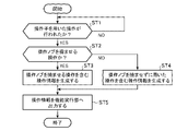
- FIG. 4 is a flowchart showing the operation input method according to Embodiment 1, showing the operation of the operation input device 2.
- the operation information generator 22 determines whether or not an operation using the operator 21 has been performed (step ST1). For example, the operation information generation unit 22 acquires detection information of an operation using the operation element 21 from at least one of the touch panel 3 and the detection unit 212, and when the acquired detection information is valid, the operation information generation unit 22 uses the operation element 21. It is determined that an operation has been performed.
- the operation information generation unit 22 determines that the detection information of the rotation of the operation knob 211 is valid, and determines that the rotation amount is less than the threshold, it is determined that the detected information is invalid. Further, the operation information generation unit 22 determines that the detection information of the operation of bending the operation knob 211 is effective when the ON time during which any one of the push button switches 212a, 212b, and 212c is in the ON state is equal to or greater than the threshold. , and if the ON time is less than the threshold, it is determined that the detection information is invalid.
- step ST1 When determining that an operation using the manipulator 21 has not been performed (step ST1; NO), the operation information generation unit 22 repeats the determination of step ST1 until an operation using the manipulator 21 is performed. When it is determined that an operation using the manipulator 21 has been performed (step ST1; YES), the operation information generation unit 22 determines whether or not the manipulation using the manipulator 21 is an operation to bend the manipulation knob 211. (step ST2).
- the operation information generation unit 22 determines that the operation using the operation element 21 is an operation to bend the operation knob 211. Further, when the valid detection information is acquired from the touch panel 3, the operation information generation unit 22 determines that the operation using the operation knob 21 is not the operation to bend the operation knob 211, and the operation using the operation element 21 It is determined that it is a rotation operation of
- the operation information generator 22 determines that the operation using the operator 21 is an operation to bend the operation knob 211 (step ST2; YES), it generates operation information including an operation to bend the operation knob 211. (Step ST3). Further, when it is determined that the operation using the manipulator 21 is not the operation to bend the manipulation knob 211 (step ST2; NO), the manipulation information generation unit 22 determines that the manipulation performed without bending the manipulation knob 211 is is generated (step ST4).
- the operation information includes, for example, the XY coordinates of the operation knob 211 calculated based on the position coordinates of the contact portions 213a to 213c of the operation knob 211 on the touch surface, the rotation direction and amount of rotation of the operation knob 211, and the push button switch. Information indicating the on or off state of 212a-212c is included.
- the operation information generation unit 22 generates operation information using valid detection information acquired from the time when valid detection information is first acquired until the reference time for determining one operation has passed. For example, if the detection information acquired within the reference time is the detection information of an operation of bending the operation knob 211, the operation information generation unit 22 moves the operation knob 211 once, similar to a mouse click operation. Operation information indicating an operation of selecting target information by bending is generated.
- the operation information generation unit 22 performs By bending the operation knob 211 twice at short intervals, operation information indicating an operation of selecting target information is generated. If the detection information acquired within the reference time is the detection information of an operation of bending the operation knob 211 three times at short intervals, the operation information generation unit 22 generates the operation knob in the same manner as the triple-click operation of the mouse. By bending 211 three times at short intervals, operation information indicating an operation for selecting target information is generated.
- the operation information generation unit 22 If the detection information acquired within the reference time is the detection information of an operation of bending the operation knob 211 four times or more at short intervals, the operation information generation unit 22 generates an operation similar to a long-click operation of the mouse. By flexing the knob 211 four times or more at short intervals, operation information indicating an operation for selecting target information is generated. Further, when the detection information acquired within the reference time is a rotation operation of the operation knob 211 in a flexed state, the operation information generation unit 22 generates an operation similar to a drag-and-drop operation using a mouse, for example. , generates operation information indicating an operation to move the target information on the display screen.
- the operation information generation unit 22 outputs the generated operation information to the function execution unit 5 (step ST5).
- the function execution unit 5 acquires operation information from the operation information generation unit 22 and executes a function corresponding to the operation indicated by the acquired operation information.
- the function execution unit 5 then outputs display information corresponding to the function being executed to the display processing unit 23 .
- the display processing unit 23 displays display information on the LCD 4 .
- the LCD 4 displays a map screen, a camera screen, a menu screen, or an audio playback screen.
- Function execution unit 5 outputs display information indicating operation details such as the XY coordinates of operation knob 211 , the rotation direction and amount of rotation of operation knob 211 included in the operation information to display processing unit 23 .
- the display processing unit 23 reflects the content of the operation based on the display information in the screen display of the function corresponding to the operation indicated by the operation information.
- the operation input device 2 includes a processing circuit for executing the processing from step ST1 to step ST5 shown in FIG.
- the processing circuit may be dedicated hardware, or may be a CPU that executes a program stored in memory.
- FIG. 5A is a block diagram showing the hardware configuration that implements the functions of the operation input device 2.
- FIG. 5B is a block diagram showing a hardware configuration for executing software realizing the functions of the operation input device 2.
- the input interface 100 includes detection information output from the detection unit 212 included in the touch panel 3 or the operator 21 to the operation information generation unit 22, or output from the function execution unit 5 to the display processing unit 23. It is an interface that relays display information.
- the output interface 101 is an interface that relays operation information output from the operation information generation unit 22 to the function execution unit 5 .
- the processing circuit 102 may be, for example, a single circuit, multiple circuits, a programmed processor, a parallel programmed processor, an ASIC, an FPGA, or any of these. A combination of is applicable.
- the functions of the operation information generation unit 22 and the display processing unit 23 in the operation input device 2 may be realized by separate processing circuits, or these functions may be collectively realized by one processing circuit.
- the processing circuit is the processor 103 shown in FIG. 5B
- the functions of the operation information generation unit 22 and the display processing unit 23 in the operation input device 2 are realized by software, firmware, or a combination of software and firmware. Note that software or firmware is written as a program and stored in the memory 104 .
- the processor 103 implements the functions of the operation information generation unit 22 and the display processing unit 23 in the operation input device 2 by reading and executing the programs stored in the memory 104 .
- the operation input device 2 includes a memory 104 for storing a program that, when executed by the processor 103, results in the processing of steps ST1 to ST5 shown in FIG. These programs cause the computer to execute the procedures or methods of the processing performed by the operation information generating section 22 and the display processing section 23 .
- the memory 104 may be a computer-readable storage medium storing a program for causing a computer to function as the operation information generating section 22 and the display processing section 23.
- the memory 104 corresponds to, for example, nonvolatile or volatile semiconductor memory such as RAM, ROM, flash memory, EPROM, EEPROM, magnetic disk, flexible disk, optical disk, compact disk, mini disk, DVD, and the like.
- a part of the functions of the operation information generation unit 22 and the display processing unit 23 in the operation input device 2 may be realized by dedicated hardware, and a part may be realized by software or firmware.
- the operation information generation unit 22 realizes its functions by the processing circuit 102, which is dedicated hardware
- the display processing unit 23 implements its functions by the processor 103 reading and executing a program stored in the memory 104.
- the processing circuitry may implement the above functions in hardware, software, firmware, or a combination thereof.
- the operation input device 2 generates the operator 21 having the operation knob 211 and the detection unit 212, the operation information indicating the operation using the operator 21, and the function execution unit 5 is provided with an operation information generation unit 22 that outputs operation information, and the operation information generation unit 22 generates operation information indicating an operation of bending the operation knob 211 detected by the detection unit 212 . Since the function to be executed can be designated by a natural operation of bending the operation knob 211 by changing the gripping force, the operation input device 2 can handle the desired function regardless of the number of fingers gripping the manipulator 21. You can perform operations to Furthermore, since a function to be executed is designated by a natural operation, the information processing apparatus 1 including the operation input device 2 reduces the possibility of erroneously executing a function different from the intended function.
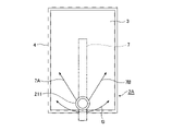
- FIG. 6 is a front view showing a configuration example of the operation input device 2A according to the second embodiment.
- the operation knob 211 included in the operation input device 2A is provided so as to be slidable in a pendulum shape on the touch surface of the touch panel 3 .
- the LCD 4 is provided with an arm 7 .
- One end of the arm 7 is rotatably supported on the back side of the LCD 4 , and the other end is bent toward the front side of the LCD 4 .
- An operation knob 211 is connected to the end portion of the arm 7 bent toward the front side of the LCD 4 .
- the operation knob 211 is slidable in the direction of arrow B on the touch surface of the touch panel 3 with one end of the arm 7 as the center of rotation. Further, the user can rotate the operating knob 211 while sliding the gripped operating knob 211 in the arrow B direction. A slide operation of the operation knob 211 is detected by the touch panel 3 . As shown in FIG. 6, a spring 7A and a spring 7B are attached to the arm 7 on the rear side of the LCD 4. As shown in FIG. When the user releases the operation knob 211, the arm 7 returns to a position where the load of the spring 7A and the load of the spring 7B are balanced, and the operation knob 211 returns to the central position of the slide movement locus.
- the mechanism for returning the operation knob 211 to the central position is not limited to the springs 7A and 7B, and magnets, dampers, or the like may be used.
- the operation knob 211 may return to the central position by the weight of the arm 7 and the operation knob 211 .
- FIG. 7 is a flow chart showing the operation input method according to Embodiment 2, and shows the operation of the operation input device 2A.
- the operation information generator 22 included in the operation input device 2A determines whether the operation knob 211 is being slid (step ST1a). For example, the operation information generator 22 acquires detection information about the amount of slide movement of the operation knob 211 from the touch panel 3, and determines that the operation knob 211 has been slid when the detection information is valid. For the determination of whether the detection information is valid or invalid, for example, when the amount of slide movement of the contact portion of the operation knob 211 on the touch surface of the touch panel 3 is equal to or greater than a threshold value, it is determined that the detection information is valid, and the amount of slide movement is determined. is less than the threshold, it is determined that the detection information is invalid.
- step ST1a When it is determined that the operation knob 211 is not being slid (step ST1a; NO), the operation input device 2A terminates the series of processes in FIG. The operation input device 2A repeatedly executes the processing of FIG. 7 until the operation knob 211 is slid.
- the operation information generation unit 22 determines whether or not an operation to bend the operation knob 211 has been performed (step ST2a). For example, the operation information generation unit 22 acquires detection information of an operation to bend the operation knob 211 from the detection unit 212, and determines that an operation to bend the operation knob 211 has been performed when the detection information is valid. Determination as to whether the switch is valid or invalid is performed, for example, by bending the operation knob 211 when the ON time during which any one of the push button switches 212a, 212b, and 212c is in the ON state is equal to or greater than a threshold. is valid, and if the ON time is less than the threshold, it is determined that the detection information is invalid.
- step ST2a NO
- the operation input device 2A terminates the series of processes in FIG. After that, the operation input device 2A outputs the operation information indicating the slide operation of the operation knob 211 to the function executing section 5.
- FIG. The function execution unit 5 acquires operation information from the operation information generation unit 22 and executes a function corresponding to the slide operation indicated by the operation information.
- the function execution unit 5 outputs display information corresponding to the function being executed to the display processing unit 23 .
- the display processing unit 23 displays display information on the LCD 4 .
- the screen display of the LCD 4 changes according to the slide operation of the operation knob 211 when the operation to bend the operation knob 211 is not performed.
- the operation information generation unit 22 determines that the operation to bend the operation knob 211 has been performed (step ST2a; YES)
- the operation information generation unit 22 generates an operation indicating a combination of the operation of sliding the operation knob 211 and the operation of bending the operation knob 211 .
- Information is generated, and the generated operation information is output to the function execution unit 5 .
- the operation information includes, for example, the slide movement amount of the operation knob 211 calculated based on the position coordinates of the contact portions 213a to 213c of the operation knob 211 on the touch surface, the XY coordinates of the operation knob 211, and the push button switches 212a to 213c. 212c is included.
- the function execution unit 5 acquires operation information from the operation information generation unit 22 and executes a function corresponding to the operation indicated by the acquired operation information.
- the function execution unit 5 then outputs display information corresponding to the function being executed to the display processing unit 23 .
- the display processing unit 23 displays display information on the LCD 4 .
- the display processing unit 23 causes the operation to bend the operation knob 211 .
- the screen display on the LCD 4 at the time of execution is maintained (step ST3a). The user can perform the slide operation of the operation knob 211 with respect to the screen display at the time when the operation of bending the operation knob 211 is performed.
- the operation information generator 22 determines whether or not the operation knob 211 has returned to the central position of the slide movement locus (step ST4a). For example, when the XY position of the operation knob 211 detected by the touch panel 3 is the center position of the slide movement trajectory, the operation information generator 22 determines that the operation knob 211 has returned to the center position of the slide movement trajectory. Further, when the XY position of the operation knob 211 is not the center position of the slide movement trajectory, the operation information generation unit 22 determines that the operation knob 211 has not returned to the center position of the slide movement trajectory.
- the operation information generation unit 22 outputs to the display processing unit 23 the determination result as to whether or not the operation knob 211 has returned to the center position of the slide movement locus.
- the display processing unit 23 cancels the maintenance of the screen display at the time when the operation to bend the operation knob 211 is performed (step ST5a).
- step ST4a determines whether or not an operation to bend the operation knob 211 has been performed.
- step ST6a determines whether or not an operation to bend the operation knob 211 has been performed.
- step ST6a If the operation knob 211 has not been returned to the central position of the slide movement locus and is not bent (step ST6a; NO), the display processing unit 23 proceeds to the process of step ST3a. Returning, the screen display of the function corresponding to the slide operation of the operation knob 211 is maintained.
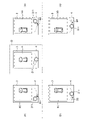
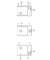
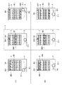
- FIG. 8 is a screen diagram showing a display example when performing processing for selecting target item information from a plurality of items of item information by an operation combining the operation of sliding the operation knob 211 and the operation of bending the operation knob 211 .
- Item information is, for example, menu information.
- the menu selection screen shown in FIG. 8 is a selection screen for selecting target item information from a plurality of item information (menu information), and is displayed on the LCD 4 provided with the touch panel 3 .
- a first list 8A and a second list 8B are displayed on the menu selection screen.
- the first list 8A is a list in which a plurality of pieces of menu information of selection candidates are displayed side by side.
- the second list 8B is a list in which a plurality of items of menu information in the first list 8A are displayed vertically.
- the menu selection screen surrounded by the dashed line with symbol C is the menu selection screen when the operation knob 211 is at the center position of the slide movement locus.
- the menu selection screen shown on the (A) side of FIG. 8 with the dashed line as the boundary shows the menu selection screen when the operation knob 211 that is not bent is slid.
- the menu selection screen shown on the (B) side of the dashed line is obtained by bending the operation knob 211 once while the menu selection screen shown on the (A) side is displayed on the LCD 4. It shows the menu selection screen when the operation knob 211 is released later and the operation knob 211 returns to the center position of the slide movement locus.
- the display processing unit 23 enlarges or reduces the display of the menu information in the second list 8B according to the slide operation of the operation knob 211. For example, in the second list 8B in the menu selection screen enclosed by the dashed line to which the symbol C is attached, the menu information is displayed with the initial value of the display magnification. When the operation knob 211 is bent while the menu information is being displayed on the LCD 4 at the initial value of the display magnification, the display processing unit 23 bends the operation knob 211 as shown in (B). Maintains the menu selection screen at the time when the operation to change is performed.
- the display processing unit 23 reduces the display of the menu information of the second list 8B.
- the display processing unit 23 maintains the menu selection screen including the second list 8B in which the display of the menu information is reduced. Thereafter, even if the user releases the operation knob 211 and slides the operation knob 211 in the direction of the arrow B3 to return to the central position, the operation to bend the operation knob 211 is not performed as shown in (B).
- the menu selection screen at the point in time is maintained. Since the screen display changed by the sliding operation of the operation knob 211 is maintained by the natural operation of bending the operation knob 211, the user can perform the next operation on the changed screen display without performing the slide operation again. It is possible.
- the display processing unit 23 enlarges the display of the menu information in the second list 8B.
- the display processing unit 23 maintains the menu selection screen including the second list 8B in which the display of the menu information is enlarged. Thereafter, even if the user releases the operation knob 211 and slides the operation knob 211 in the direction of the arrow B4 to return to the central position, the operation to bend the operation knob 211 is not performed as shown in (B).
- the menu selection screen at the point in time is maintained. Since the screen display changed by the sliding operation of the operation knob 211 is maintained by the natural operation of bending the operation knob 211, the user can perform the next operation on the changed screen display without performing the slide operation again. It is possible.
- FIG. 9 is a screen diagram showing a display example when performing a process of enlarging or reducing the bird's-eye view image of the vehicle by an operation combining the operation of sliding the operation knob 211 and the operation of bending the operation knob 211 .
- the bird's-eye view image of the vehicle is, for example, an image captured by the imaging unit 6 and displayed on the LCD 4 .
- a bird's-eye view image of the vehicle is displayed at the initial value of the display magnification on the screen 9 enclosed by the dashed line to which the symbol D is attached.
- the display processing unit 23 enlarges or reduces the bird's-eye view image of the vehicle displayed on the LCD 4 according to the slide operation of the operation knob 211 .
- the screen shown on the (A) side of the dashed line in FIG. 9 shows the screen when the operation knob 211 that is not bent is slid. Further, the screen shown on the (B) side of the dashed line is displayed on the LCD 4 when the screen shown on the (A) side is displayed on the LCD 4, and the operation knob 211 is opened after the operation of bending the operation knob 211 once. , and the operation knob 211 returns to the central position of the slide movement locus.
- the display processing unit 23 displays a bird's-eye view image of the vehicle as shown on the left side of the screen 9 surrounded by the dashed line with the symbol D. to shrink.
- the display processing unit 23 maintains the screen 9A in which the bird's-eye view image of the vehicle is reduced. Thereafter, even if the user releases the operation knob 211 and slides the operation knob 211 in the direction of the arrow B3 to return to the central position, the operation to bend the operation knob 211 is not performed as shown in (B).
- the screen 9A at the time when it was performed is maintained. Since the screen display changed by the sliding operation of the operation knob 211 is maintained by the natural operation of bending the operation knob 211, the user can perform the next operation on the changed screen display without performing the slide operation again. It is possible.
- the display processing unit 23 enlarges the bird's-eye view image of the vehicle.
- the display processing unit 23 maintains the screen 9B in which the bird's-eye view image of the vehicle is enlarged. Thereafter, even if the user releases the operation knob 211 and slides the operation knob 211 in the direction of the arrow B4 to return to the central position, the operation to bend the operation knob 211 is not performed as shown in (B).
- the screen 9B at the time when it was performed is maintained. Since the screen display changed by the sliding operation of the operation knob 211 is maintained by the natural operation of bending the operation knob 211, the user can perform the next operation on the changed screen display without performing the slide operation again. It is possible.
- FIG. 10 is a screen diagram showing a display example when the bird's-eye view image of the vehicle is slid left and right by an operation combining the operation of sliding the operation knob 211 and the operation of bending the operation knob 211 .
- the bird's-eye view image of the vehicle is, for example, an image captured by the imaging unit 6 and displayed on the LCD 4 .
- a bird's-eye view image of the vehicle at the initial position is displayed on the screen 9 surrounded by a dashed line denoted by D.
- the display processing unit 23 slides the bird's-eye view image of the vehicle displayed on the LCD 4 left and right in accordance with the slide operation of the operation knob 211 .
- the screen shown on the (A) side of FIG. 10 with the dashed line as the boundary shows the screen when the operation knob 211 that is not bent is slid. Further, the screen shown on the (B) side of the dashed line is displayed on the LCD 4 when the screen shown on the (A) side is displayed on the LCD 4, and the operation knob 211 is opened after the operation of bending the operation knob 211 once. The screen is shown when the operation knob 211 returns to the center position of the slide movement locus by releasing the hand from the .
- the display processing unit 23 displays a bird's-eye view image of the vehicle as shown on the left side of the screen 9 surrounded by the dashed line with the symbol D. slide to the right.
- the display processing unit 23 maintains the screen 9C in which the bird's-eye view image of the vehicle is slid to the right. Thereafter, even if the user releases the operation knob 211 and slides the operation knob 211 in the direction of the arrow B3 to return to the central position, the operation to bend the operation knob 211 is performed as shown in (B).
- the screen 9C at the time when it was broken is maintained. Since the screen display changed by the slide operation of the operation knob 211 is maintained by the natural operation of bending the operation knob 211, the user can perform the next operation on the changed screen display without performing the slide operation again. It is possible.
- the display processing unit 23 When the operation knob 211 is slid in the direction of arrow B2 from the center position of the slide movement locus, the display processing unit 23 enlarges the bird's-eye view image of the vehicle. At this time, when an operation to bend the operation knob 211 is performed, the display processing unit 23 maintains the screen 9D in which the bird's-eye view image of the vehicle is slid to the left. Thereafter, even if the user releases the operation knob 211 and slides the operation knob 211 in the direction of the arrow B4 to return to the central position, the operation to bend the operation knob 211 is not performed as shown in (B). The screen 9D at the time it was performed is maintained. Since the screen display changed by the sliding operation of the operation knob 211 is maintained by the natural operation of bending the operation knob 211, the user can perform the next operation on the changed screen display without performing the slide operation again. It is possible.
- FIG. 11 is a screen diagram showing a display example when CD playback processing is performed by an operation combining the operation of sliding the operation knob 211 and the operation of bending the operation knob 211 .
- the CD playback screen is a screen for selecting a track (T), volume adjustment (V) and playback speed adjustment (S), and is displayed on the LCD 4.
- T track
- V volume adjustment
- S playback speed adjustment
- FIG. 11 the volume control (V) is selected on the screen 10 surrounded by the dashed line with the symbol E.
- Function execution unit 5 selects an adjustment item on the CD playback screen according to the slide operation of operation knob 211 , and display processing unit 23 displays the selection of the adjustment item on the CD playback screen on LCD 4 .
- the screen shown on the (A) side of FIG. 11 with the dashed line as the boundary shows the screen when the operation knob 211 that is not bent is slid. Further, the screen shown on the (B) side of the dashed line is displayed on the LCD 4 when the screen shown on the (A) side is displayed on the LCD 4, and the operation knob 211 is opened after the operation of bending the operation knob 211 once. The screen is shown when the operation knob 211 returns to the center position of the slide movement locus by releasing the hand from the .
- the display processing unit 23 displays the track (T) as shown on the left side of the screen 10 surrounded by the dashed line with the symbol E.
- the selected CD playback screen 10A is displayed on the LCD 4. - ⁇ At this time, when an operation to bend the operation knob 211 is performed, the display processing unit 23 maintains the CD playback screen 10A. Thereafter, even if the user releases the operation knob 211 and the operation knob 211 slides in the direction of the arrow B3 to return to the central position, the operation to bend the operation knob 211 is performed as shown in (B).
- the CD playback screen 10A at the time of opening is maintained. Since the screen display changed by the sliding operation of the operation knob 211 is maintained by the natural operation of bending the operation knob 211, the user can perform the next operation on the changed screen display without performing the slide operation again. It is possible.
- the display processing unit 23 causes the LCD 4 to display the CD playback screen 10B with playback speed adjustment (S) selected.
- S playback speed adjustment
- the display processing section 23 maintains the CD playback screen 10B.
- the operation to bend the operation knob 211 is performed as shown in (B).
- the CD playback screen 10B at the time of opening is maintained. Since the screen display changed by the sliding operation of the operation knob 211 is maintained by the natural operation of bending the operation knob 211, the user can perform the next operation on the changed screen display without performing the slide operation again. It is possible.
- FIG. 12 is a screen diagram showing a display example when the processing of sliding the center coordinates 14 of the map around the vehicle is performed by an operation combining the operation of sliding the operation knob 211 and the operation of bending the operation knob 211 . .
- the map screen 11 is displayed on the LCD 4 by the display processing section 23 .
- An image 12 showing the current position of the vehicle and a route 13 are displayed on the map screen 11 .
- the function executing section 5 executes a navigation function of guiding the vehicle along the route 13 . Further, the function execution unit 5 changes the center coordinates 14 of the map screen in accordance with the sliding operation of the operation knob 211 that is being bent.
- the display processing unit 23 displays the change of the central coordinates 14 of the map screen on the LCD 4 .
- the display processing unit 23 moves the image 12 in the direction of the arrow F1 on the route 13,
- the LCD 4 displays a map screen 11A in which the position behind the vehicle on the route 13 is changed to the center coordinates 14.
- the display processing unit 23 moves the image 12 in the direction of arrow F2 on the route 13.
- the LCD 4 displays a map screen 11B in which the position in front of the vehicle on the route 13 is changed to the center coordinates 14.
- the image 12 indicating the current position of the vehicle may be continuously moved forward or backward on the route 13 .
- the display processing unit 23 may determine the moving distance or moving speed for moving the image 12 forward or backward on the route 13 according to the amount of slide movement of the operation knob 211 that is being bent.
- the center coordinates 14 of the map screen are changed according to the sliding operation of the operation knob 211 that is being operated to bend, when the operation knob 211 returns to the center position, the center coordinates 14 of the map screen change to the current vehicle position ( It may be displayed so as to return to the position of the image 12).
- the display processing unit 23 may enlarge or reduce the display of the map screen according to the slide operation of the operation knob 211 that has been restored from the bending. For example, the display processing unit 23 displays the map screen on the LCD 4 at a display magnification corresponding to the slide operation amount of the operation knob 211 . Further, the display processing unit 23 may change the orientation of the image displayed on the LCD 4 in accordance with the slide operation of the operation knob 211 restored from the bending. For example, the function execution unit 5 changes the direction of the imaging unit 6 (the camera swings) in accordance with the slide operation of the operation knob 211 restored from the flexure.
- the function execution unit 5 may switch the function to be executed according to the slide operation of the operation knob 211 that has been restored from the flexure.
- the display processing unit 23 switches to a screen corresponding to the function executed by the function execution unit 5 in accordance with the slide operation of the operation knob 211 restored from the bending.
- the display screen of the LCD 4 switches from a camera image display screen to a menu selection screen or switches to a map display screen in accordance with a slide operation of the operation knob 211 restored from bending.
- the function execution unit 5 may switch the function to be executed according to the slide position of the operation knob 211 restored from the flexure. For example, when the operation knob 211 moves to the first position of the slide movement trajectory, the function execution unit 5 executes the CD playback function and adjusts the volume (V) according to the rotation operation of the operation knob 211 . Furthermore, when the operation knob 211 moves to the second position (a position different from the first position) on the slide movement locus, the function execution unit 5 executes the control function of the air conditioner, and the rotation operation of the operation knob 211 Adjust temperature accordingly.
- the display processing unit 23 may change the transparency of the image displayed on the LCD 4 according to the slide position of the operation knob 211 restored from the flexure. For example, the display processing unit 23 increases the transparency of the image displayed on the LCD 4 when the operation knob 211 is slid to the left from the center position, and increases the transparency of the image displayed on the LCD 4 when the operation knob 211 is slid to the right from the center position. Reduce the transparency of the displayed image.
- the display processing unit 23 may change the amount of information to be displayed on the LCD 4 according to the slide operation of the operation knob 211 restored from the bending.
- the amount of information to be displayed on the LCD 4 includes the number of pieces of display information or the degree of detail of the content. For example, on a setting screen displaying a plurality of pieces of image information, it is conceivable to reduce the number of pieces of image information or simplify the image in accordance with the slide operation of the operation knob 211 that has been restored from bending. Although the slide operation of the operation knob 211 restored from bending has been described so far, the above process may be executed in accordance with the slide operation of the operation knob 211 that is being bent.
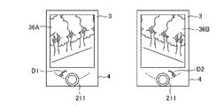
- FIG. 13A is a screen diagram showing a display example when the process of displaying the scenery after the vehicle has passed the route 13 is performed by an operation combining the operation of sliding the operation knob 211 and the operation of bending the operation knob 211.
- FIG. 13B is a screen diagram showing a display example when the process of displaying the scenery before the vehicle passes through the route 13 is performed by an operation combining the operation of sliding the operation knob 211 and the operation of bending the operation knob 211 . is.
- the image 15A or 15B of the scene outside the vehicle is displayed on the LCD 4 by the display processing unit 23.
- the image 15A or 15B of the scenery outside the vehicle may be, for example, an image captured by the imaging unit 6, or may be an existing image such as a street view.
- the function execution unit 5 changes the center coordinates 14 of the map screen according to the slide operation of the operation knob 211 that is being bent.
- the display processing unit 23 displays the image 15A or 15B of the scenery outside the vehicle at the center coordinates 14 of the map screen on the LCD 4 .
- the display processing unit 23 moves the image 12 ahead of the route 13 as shown in FIG. 13A. to change the position behind the vehicle on route 13 to center coordinates 14 . Then, the display processing unit 23 displays the image 15A of the scenery outside the vehicle at the changed center coordinates 14 on the LCD 4 . Further, an arrow F3 indicating the direction in which the vehicle exists at the center coordinates 14 may be displayed in the image 15A of the scenery outside the vehicle.
- the display processing unit 23 changes the image 12 to the route 13 as shown in FIG. 13B. By moving forward, the position ahead of the vehicle on the route 13 is changed to center coordinates 14 . Then, the display processing unit 23 displays the image 15B of the scenery outside the vehicle at the changed center coordinates 14 on the LCD 4 . Also, an arrow F4 indicating the direction in which the vehicle exists at the center coordinates 14 may be displayed in the image 15B of the scenery outside the vehicle.
- the display processing unit 23 may enlarge or reduce the display of the image 15A or 15B of the scenery outside the vehicle according to the slide operation of the operation knob 211 restored from the bending.
- FIG. 14 shows a display example when processing is performed to display the guide line 17 for reversing on the image 16 behind the vehicle by an operation combining the operation of sliding the operation knob 211 and the operation of bending the operation knob 211 . It is a screen figure.
- the display processing unit 23 displays on the LCD 4 an image 16 of the rear of the vehicle including the guide line 17 for reversing the vehicle.
- the transmittance of the guide wire 17 has an intermediate value at the center position of the slide movement locus of the operation knob 211 .
- the display processing unit 23 displays an image 16A in which the transparency of the guide line 17 is increased on the LCD 4 when the operation knob 211, which is being operated to be bent, is slid in the direction of the arrow B1 from the center position of the slide movement locus. indicate.
- the guide line 17 in the image 16A is transparent because the transparency is set to the maximum value.
- the display processing unit 23 displays the image 16B in which the transparency of the guide line 17 is lowered. Display on LCD4. The guide line 17 in the image 16B is clearly displayed because the transparency is set to the minimum value.
- FIG. 15 shows a display example when processing for displaying an obstacle warning image 19 on a vehicle bird's-eye view image 18 is performed by an operation combining a sliding operation of the operation knob 211 and an operation of bending the operation knob 211 . It is a screen figure.
- the display processing unit 23 displays on the LCD 4 a bird's-eye view image 18 of the vehicle including an obstacle warning image 19 .
- the transparency of the warning image 19 has an intermediate value at the center position of the slide movement locus of the operation knob 211 .
- the display processing unit 23 displays an image 18A obtained by increasing the transparency of the warning image 19 on the LCD 4 when the operation knob 211, which is being operated to be bent, is slid in the direction of the arrow B1 from the center position of the slide movement locus. indicate.
- the warning image 19 in the image 18A is transparent because the transparency is set to the maximum value.
- the display processing unit 23 displays the image 18B in which the transparency of the warning image 19 is lowered on the LCD 4. to display.
- the warning image 19 in the image 18B is clearly displayed because the transparency is set to the minimum value.
- FIG. 16 is a screen diagram showing a display example when processing for controlling the image pickup direction of the image pickup unit 6 that picks up an image of a person is performed by an operation combining the operation of sliding the operation knob 211 and the operation of bending the operation knob 211 . is.
- the display processing unit 23 displays an image 31 of a person captured by the imaging unit 6 on the LCD 4 .
- An image 31 of a person captured from the front is displayed on the LCD 4 at the center position of the slide movement locus of the operation knob 211 .
- the function executing unit 5 controls the imaging direction of the imaging unit 6 when the operation knob 211, which is being operated to be bent, is slid in the direction of the arrow B1 from the center position of the slide movement trajectory. 6 is changed so that the right side of the person is imaged.
- the display processing unit 23 displays on the LCD 4 an image 31A in which the right side of the person is mainly captured.
- the function execution unit 5 controls the image pickup direction of the image pickup unit 6 to perform the image pickup operation.
- the direction of the part 6 is changed so as to image the left side of the person.
- the display processing unit 23 displays on the LCD 4 an image 31B in which the left side of the person is mainly captured.
- FIG. 17 shows an example of a display when the processing for controlling the imaging direction of the imaging unit 6 that captures the bird's-eye view image 32 of the vehicle is performed by an operation combining the operation of sliding the operation knob 211 and the operation of bending the operation knob 211 . It is a screen diagram showing .
- the display processing unit 23 displays a bird's-eye view image 32 of the vehicle captured by the imaging unit 6 on the LCD 4 .
- a bird's-eye view image 32 obtained by imaging the vehicle from directly above is displayed on the LCD 4 .
- the function executing unit 5 controls the imaging direction of the imaging unit 6 when the operation knob 211, which is being operated to be bent, is slid in the direction of the arrow B1 from the center position of the slide movement trajectory. 6 is changed so as to image the left side of the vehicle.
- the display processing unit 23 displays on the LCD 4 an image 32A in which the left side of the vehicle is mainly captured.
- the function execution unit 5 controls the image pickup direction of the image pickup unit 6 to perform the image pickup operation.
- the direction of the part 6 is changed to image the right side of the vehicle.
- the display processing unit 23 displays on the LCD 4 an image 32B in which the right side of the vehicle is mainly captured.
- FIG. 18 is a screen diagram showing a display example when a process of transitioning a plurality of types of processing screens is performed by an operation combining the operation of sliding the operation knob 211 and the operation of bending the operation knob 211 .
- the display processing unit 23 displays on the LCD 4 a bird's-eye view image 32 of the vehicle taken from directly above at the center position of the slide movement locus of the operation knob 211 .
- the function execution unit 5 switches the function to be executed to the control function of the air conditioner when the operation knob 211 that is being bent is slid in the direction of the arrow G1 from the center position of the slide movement locus.
- the display processing unit 23 displays the control screen 33 of the air conditioner on the LCD 4 .
- the function execution unit 5 switches the function to be executed to the vehicle navigation function.
- the display processing unit 23 displays on the LCD 4 the map screen 11 including the route that the vehicle travels.
- the display processing unit 23 displays the image of the vehicle imaged by the imaging unit 6 attached to the vehicle.
- a front image 34 is displayed on the LCD 4.
- the display processing unit 23 displays the image of the rear of the vehicle captured by the image capturing unit 6 attached to the vehicle. is displayed on the LCD 4.
- Images corresponding to various functions executed by the function execution unit 5 can be switched in stages and displayed on the LCD 4 by a natural operation of sliding the operation knob 211 that is being bent. This allows the user to operate various functions.
- the sliding operation of the operation knob 211 that is being bent has been described so far, the above processing may be executed in response to the sliding operation of the operation knob 211 that is restored from the bending.
- FIG. 19 is a screen diagram showing a display example (1) when a process of selecting item information from a menu list is performed by an operation combining the operation of sliding the operation knob 211 and the operation of bending the operation knob 211.
- FIG. . The menu selection screen shown in FIG. 19 is a selection screen for selecting target menu information from a plurality of menu information, and is displayed on LCD 4 provided with touch panel 3 .
- a first list 8A and a second list 8B are displayed on the menu selection screen.
- the first list 8A is a list in which a plurality of pieces of menu information of selection candidates are displayed side by side.
- the second list 8B is a list in which a plurality of items of menu information in the first list 8A are displayed vertically.
- the menu selection screen surrounded by the dashed line with symbol H is the menu selection screen when the operation knob 211 is at the center position of the slide movement locus.
- the menu selection screen shown on the side (A) of FIG. 19 with the dashed line as the boundary shows the menu selection screen when the operation knob 211, which is being bent, is slid.
- the menu selection screen shown on the (B) side of the dashed line is the operation knob 211 that the user releases and returns to its flexure while the menu selection screen shown on the (A) side is displayed on the LCD 4. shows the menu selection screen when has returned to the center position of the slide movement locus.
- the function execution unit 5 selects menu information in the first list 8A and the second list 8B according to the slide operation of the operation knob 211 that is being bent. For example, in the menu selection screen enclosed by the dashed line with symbol H, the menu information 8A4 of the first list 8A is selected and the menu information 8B4 of the second list 8B is selected.
- the operation knob 211 that has been flexed returns to the center position of the slide movement trajectory.
- the display processing unit 23 maintains the menu selection screen at the time when the deflection is restored, as shown in (B) side.
- function execution unit 5 selects menu information 8A1 of first list 8A according to the slide movement amount of operation knob 211. , selects the menu information 8B1 of the second list 8B.
- the display processing unit 23 displays on the LCD 4 the first list 8A in which the menu information 8A1 is selected and the second list 8B in which the menu information 8B1 is selected.
- the operation knob 211 that has been restored to its flexure slides in the direction of the arrow B3.
- the display processing unit 23 returns to the center position of the slide movement trajectory by pressing, the display processing unit 23 maintains the menu selection screen at the time when the deflection is restored, as shown in (B) side.
- the function execution unit 5 changes the menu information 8A7 of the first list 8A according to the slide movement amount of the operation knob 211. Select to select the menu information 8B7 of the second list 8B.
- the display processing unit 23 displays on the LCD 4 the first list 8A in which the menu information 8A7 is selected and the second list 8B in which the menu information 8B7 is selected.
- the operation knob 211 that has been restored to its flexure slides in the direction of the arrow B4.
- the display processing unit 23 returns to the center position of the slide movement trajectory by pressing, the display processing unit 23 maintains the menu selection screen at the time when the deflection is restored, as shown in (B) side.
- the screen display changed by the slide operation of the operation knob 211 is maintained by the natural operation of bending the operation knob 211, so that the user can change the screen display without performing the slide operation again. It is possible to: Although the sliding operation of the operation knob 211 that is being bent has been described so far, the above processing may be executed in response to the sliding operation of the operation knob 211 that is restored from the bending.
- FIG. 20 is a screen diagram showing a display example (2) when the process of selecting item information from the menu list is performed by an operation combining the operation of sliding the operation knob 211 and the operation of bending the operation knob 211.
- the menu selection screen shown in FIG. 20 is a selection screen for selecting target menu information from a plurality of menu information, and is displayed on the LCD 4 provided with the touch panel 3 .
- a first list 8A and a second list 8B are displayed on the menu selection screen.
- the first list 8A is a list in which a plurality of pieces of menu information of selection candidates are displayed side by side.
- the second list 8B is a list in which a plurality of items of menu information in the first list 8A are displayed vertically.
- the menu selection screen enclosed by the dashed line with symbol I is the menu selection screen when the operation knob 211 is at the center position of the slide movement locus.
- the menu selection screen shown on the (A) side of the broken line in FIG. 20 shows the menu selection screen when the operation knob 211, which is being bent, is slid.
- the menu selection screen shown on the (B) side of the dashed line is the operation knob 211 that the user releases and returns to its flexure while the menu selection screen shown on the (A) side is displayed on the LCD 4. shows the menu selection screen when has returned to the center position of the slide movement locus.
- the function execution unit 5 selects menu information in the first list 8A and the second list 8B according to the slide operation of the operation knob 211 that is being bent. For example, in the menu selection screen surrounded by the dashed line with symbol I, the menu information D is selected in the first list 8A and the second list 8B. Menu information D is menu information displayed at the center position in the first list 8A and the second list 8B.
- function execution unit 5 changes first list 8A and second list 8B according to the amount of slide movement of operation knob 211.
- Select menu information A The display processing unit 23 displays on the LCD 4 the first list 8A and the second list 8B in which the menu information A is selected.
- the operation knob 211 which has been restored to its flexure, slides in the arrow B3 direction.
- the menu information A is moved to the center position in the first list 8A and the second list 8B, as shown in (B).
- the function execution unit 5 changes the first list 8A and the second list 8B according to the slide movement amount of the operation knob 211.
- Select menu information F The display processing unit 23 displays on the LCD 4 the first list 8A and the second list 8B in which the menu information F is selected.
- the display processing unit 23 displays the first list 8A and the second list 8B in which the menu information F is selected on the LCD 4, the operation knob 211, which has been restored to its flexure, slides in the arrow B4 direction. After returning to the center position of the slide movement trajectory, the menu information F is moved to the center position in the first list 8A and the second list 8B, as shown in (B).
- the menu information selected by the sliding operation of the operation knob 211 is displayed at the center position of the list by the natural operation of bending the operation knob 211, so that the user can select by sliding the operation knob 211.
- menu information can be accurately viewed.
- the sliding operation of the operation knob 211 that is being bent has been described so far, the above processing may be executed in response to the sliding operation of the operation knob 211 that is restored from the bending.
- FIG. 21 is a screen diagram showing a display example when the process of selecting item information from the menu list is performed by an operation combining the operation of rotating the operation knob 211 and the operation of bending the operation knob 211 .
- the menu selection screen shown in FIG. 21 is a selection screen for selecting target menu information from a plurality of menu information, and is displayed on the LCD 4 provided with the touch panel 3 .
- a second list 8B is displayed on the menu selection screen.
- a second list 8B is a list in which a plurality of pieces of menu information are displayed vertically.
- the function execution unit 5 selects menu information in the second list 8B according to the rotation operation of the operation knob 211 that is being bent.
- the display processing unit 23 displays on the LCD 4 the second list 8B in which the menu information B is selected according to the rotation operation of the operation knob 211 . From this state, when the operation knob 211 that is being operated to be bent is rotated in the direction of the arrow C1, the display processing unit 23 changes the display order of the menu information B in the second list 8B as shown in FIG. is replaced with the adjacent menu information C. When the operation knob 211 that is being bent is further rotated in the direction of the arrow C2, the display processing unit 23 replaces the display order of the menu information B with the adjacent menu information D in the second list 8B.
- the operation of bending the operation knob 211 and the recovery from the bending of the operation knob 211 are continuously performed like a double-click operation of a mouse.
- the display processing unit 23 can change the display order in the list between the selected menu information and the adjacent menu information. good. Even with this operation, the user can easily perform complicated processing such as changing the display order of the menu information in the list.
- FIG. 22 is a screen diagram showing a display example when a process of rotating the map around the vehicle is performed by an operation combining the operation of rotating the operation knob 211 and the operation of bending the operation knob 211 .
- the display processing unit 23 displays the map screen 11 on the LCD 4 .
- the display processing unit 23 rotates the map screen 11 according to the rotation operation of the operation knob 211 that is being bent.
- the display processing unit 23 rotates the map screen 11 in the direction of arrow D2 as shown in FIG. Further, when the operation knob 211 that is being bent is rotated in the direction of arrow C3, the display processing unit 23 rotates the map screen 11 in the direction of arrow D1.
- the direction of the map can be changed by a natural operation of bending and rotating the operation knob 211 .
- FIG. 23 is a screen diagram showing a display example when processing for changing the direction of the image around the vehicle is performed by an operation combining the operation of rotating the operation knob 211 and the operation of bending the operation knob 211 .
- the display processing unit 23 displays images 36A and 36B around the vehicle on the LCD 4 .
- the images 36A and 36B around the vehicle may be, for example, images captured by the imaging unit 6, or may be existing images such as street view.
- the display processing unit 23 changes the orientation of the image around the vehicle in accordance with the rotation operation of the operation knob 211 that is being bent. For example, when the operation knob 211 that is being operated to bend is rotated in the direction of arrow D1, an image 36A of the surroundings of the vehicle, in which the left side of the road of the vehicle is captured, is displayed on the LCD 4 as shown in FIG. . When the operation knob 211 that is being operated to bend is rotated in the direction of the arrow D2, the display processing unit 23 displays on the LCD 4 an image 36B of the surroundings of the vehicle, in which the right side of the road of the vehicle is captured. In this way, the orientation of the image around the vehicle can be changed by a natural operation of bending and rotating the operation knob 211 .
- the operation knob 211 is provided so as to be slidably operated in a pendulum shape on the touch surface of the touch panel 3 .
- the operation information generation unit 22 generates operation information indicating an operation combining a sliding operation of the operation knob 211 and an operation of bending the operation knob 211 .
- the operation input device 2A can specify a function to be executed by an operation of sliding the operation knob 211 and an operation of bending the operation knob 211 by changing the gripping force. Therefore, the operation input device 2A can perform an operation corresponding to a desired function regardless of the number of fingers holding the operator 21 .
- the information processing apparatus 1 provided with the operation input device 2A can perform a function different from the intended function. is less likely to be executed incorrectly.
- the display processing unit 23 performs the operation of bending the operation knob 211 and the recovery from the bending of the operation knob 211.
- the screen display on the LCD 4 is maintained.
- the screen display changed by the sliding operation of the operation knob 211 is maintained by the natural operation of bending the operation knob 211 . This allows the user to perform the next operation on the changed screen display without performing the slide operation again.
- the operation information generation unit 22 performs an operation in which the operation of sliding the operation knob 211, the operation of bending the operation knob 211, and the recovery from the bending of the operation knob 211 are combined. Generates the operation information shown.
- the operation input device 2 ⁇ /b>A can perform the desired operation regardless of the number of fingers gripping the manipulator 21 by natural manipulations such as the sliding manipulation of the manipulation knob 211 , the manipulation of bending the manipulation knob 211 , and the recovery from the flexing of the manipulation knob 211 . You can perform operations corresponding to the functions of
- the display processing unit 23 causes the screen display of the LCD 4 to be displayed when the operation knob 211 is restored from the bending during the sliding operation of the operation knob 211 which is being operated to be bent. maintain.
- the screen display changed by the slide operation of the operation knob 211 is maintained by the natural operation of bending the operation knob 211 and then restoring the bending. This allows the user to perform the next operation on the changed screen display without performing the slide operation again.
- the display processing unit 23 displays on the LCD 4 a selection screen for selecting menu information from a list of a plurality of item information, and the operation knob 211 being bent is operated.
- the operation knob 211 is restored from the flexure with the menu information selected from the list by the slide operation, the selected menu information is moved to the center position of the list.
- the menu information selected by the sliding operation of the operation knob 211 is displayed at the center position of the list by the natural operation of bending the operation knob 211 . Thereby, the user can accurately visually recognize the menu information selected by the slide operation of the operation knob 211 .
- the operation information generator 22 indicates an operation in which a rotation operation of the operation knob 211, an operation of bending the operation knob 211, and a recovery from the bending of the operation knob 211 are combined. Generate operational information.
- the operation input device 2A can be operated by a natural combination of rotating the operation knob 211, bending the operation knob 211, and restoring the operation knob 211 from the bending. You can perform the operation corresponding to the desired function.
- the display processing unit 23 displays on the LCD 4 a selection screen for selecting menu information from a list of a plurality of menu information, and the operation knob 211 being bent is operated.
- the display order in the list is changed between the selected menu information and the adjacent menu information. Complicated processing such as changing the display order of menu information in the list can be easily performed by a natural operation of bending the operation knob 211 .
- the display processing unit 23 displays on the LCD 4 a selection screen for selecting menu information from a list of a plurality of menu information.
- the operation knob 211 is rotated after the return from the display is performed a plurality of times in succession, the display order in the list is changed between the selected menu information and the adjacent menu information.
- a complex process of changing the display order of menu information in the list can be easily performed by a natural operation of bending the operation knob 211 and then restoring the bending.
- the operation input device can be used, for example, in a navigation device mounted on a vehicle.
- 1 Information processing device 2, 2A Operation input device, 3 Touch panel, 4 LCD, 5 Function execution unit, 6 Imaging unit, 7 Arm, 7A, 7B Spring, 8A First list, 8A1, 8B1, 8A4, 8B4, 8A7 , 8B7 Menu information, 8B Second list, 9, 9A to 9D, 10 Screen, 10A, 10B CD playback screen, 11, 11A, 11B Map screen, 12, 15A, 15B, 31, 31A, 31B, 32A, 32B Image, 13 Route, 14 Center coordinates, 16, 16A, 16B, 18A, 18B, 34, 35, 36A, 36B Video, 17 Guide line, 18, 32 Overhead video, 19 Warning image, 21 Operator, 22 Operation information generation section, 23 display processing section, 33 control screen, 100 input interface, 101 output interface, 102 processing circuit, 103 processor, 104 memory, 211 operation knob, 211A outer frame section, 211B inner frame section, 212 detection section, 212a to 212c Push button switch, 213a to 213c Contact parts.
Landscapes
- Engineering & Computer Science (AREA)
- General Engineering & Computer Science (AREA)
- Theoretical Computer Science (AREA)
- Human Computer Interaction (AREA)
- Physics & Mathematics (AREA)
- General Physics & Mathematics (AREA)
- User Interface Of Digital Computer (AREA)
Abstract
操作入力装置(2)は、タッチパネル(3)のタッチ面上に回転可能に設けられた操作ノブ(211)および操作ノブ(211)を把持して撓ませる操作を検出する検出部(212)を有した操作子(21)と、操作子(21)を用いた操作を示す操作情報を生成し、操作に対応する機能を実行する機能実行部(5)に操作情報を出力する操作情報生成部(22)を備え、操作情報生成部(22)は、検出部(212)によって検出された操作ノブ(211)を撓ませる操作を示す操作情報を生成する。
Description
本開示は、操作入力装置、情報処理装置および操作入力方法に関する。
一つの操作子を用いた複数種類の操作によって情報処理装置に対して様々な機能を実行させる技術が提案されている。例えば、特許文献1には、ダイヤルスイッチまたはロータリースイッチである操作子と、操作子を把持する指の数を検出する指センサを備えた操作入力装置が記載されている。当該操作入力装置は、指センサの検出結果に基づいて、操作子を把持する指の数を特定し、操作入力に対する操作指令を、操作子を把持する指の数に応じて切り替える。
特許文献1に記載された操作入力装置は、別の操作に切り替える際に操作子を把持する指の数を変える必要があり、操作性が悪いという課題があった。例えば、指の数が多い方が回転させやすい操作子であっても、実行対象の機能によっては少ない指の数で不自然に操作子を回転させる必要がある。また、操作子を回転させる際にさらに指が操作子に触れると、実行対象の機能とは別の機能が誤って実行される可能性がある。
本開示は上記課題を解決するものであり、操作子を把持する指の数によらずに、目的の機能に対応する操作を行うことができる操作入力装置、情報処理装置および操作入力方法を得ることを目的とする。
本開示に係る操作入力装置は、タッチパネルのタッチ面上に回転可能に設けられた操作ノブおよび操作ノブを把持して撓ませる操作を検出する検出部を有した操作子と、操作子を用いた操作を示す操作情報を生成し、操作に対応する機能を実行する機能実行部に操作情報を出力する操作情報生成部とを備え、操作情報生成部は、検出部によって検出された操作ノブを撓ませる操作を示す操作情報を生成する。
本開示によれば、操作ノブおよび検出部を有した操作子と、操作子を用いた操作を示す操作情報を生成し、機能実行部に操作情報を出力する操作情報生成部を備え、操作情報生成部は、検出部によって検出された操作ノブを撓ませる操作を示す操作情報を生成する。操作ノブを把持する力を変えて撓ませる自然な操作によって実行対象の機能を指定できるため、本開示に係る操作入力装置は、操作子を把持する指の数によらずに、目的の機能に対応する操作を行うことができる。
実施の形態1.
図1は、実施の形態1に係る情報処理装置1の構成例を示すブロック図である。図1において、情報処理装置1は、操作入力装置2によって受け付けられた操作入力に対応する機能を実行している。例えば、情報処理装置1は、ナビゲーション装置、空調装置またはオーディオ機器である。情報処理装置1は、図1に示すように、操作入力装置2、タッチパネル3、液晶ディスプレイ(以下、LCDと記載する。)4、機能実行部5および撮像部6を備える。タッチパネル3は、静電容量方式のタッチパネルである。タッチパネル3は、パネル面における静電容量の変化を検出し、パネル面で静電容量の変化が検出された部分の位置情報およびパネル面に対する押圧情報を、操作情報生成部22に出力する。
図1は、実施の形態1に係る情報処理装置1の構成例を示すブロック図である。図1において、情報処理装置1は、操作入力装置2によって受け付けられた操作入力に対応する機能を実行している。例えば、情報処理装置1は、ナビゲーション装置、空調装置またはオーディオ機器である。情報処理装置1は、図1に示すように、操作入力装置2、タッチパネル3、液晶ディスプレイ(以下、LCDと記載する。)4、機能実行部5および撮像部6を備える。タッチパネル3は、静電容量方式のタッチパネルである。タッチパネル3は、パネル面における静電容量の変化を検出し、パネル面で静電容量の変化が検出された部分の位置情報およびパネル面に対する押圧情報を、操作情報生成部22に出力する。
LCD4は、タッチパネル3が設けられた表示部である。例えば、LCD4は、操作入力装置2から出力された映像情報を表示する。情報処理装置1が、LCD4を有したナビゲーション装置である場合、LCD4は、例えば、車室内の前席中央に取り付けられる。機能実行部5は、操作情報が示す操作に対応する機能を実行する。撮像部6は、撮影した映像データを機能実行部5に出力する。例えば、情報処理装置1が車載機器であり、撮像部6が、車両周辺の映像を撮像する車外カメラであってもよい。
操作入力装置2は、タッチパネル3のタッチ面上に設けられた操作子21を用いた操作入力を受け付ける装置であり、操作子21、操作情報生成部22および表示処理部23を備える。操作子21は、操作ノブ211および検出部212を備える。図2Aは、操作子21を示す斜視図である。操作ノブ211は、図2Aに示すように、ダイヤル形状の部材である。操作ノブ211は、タッチパネル3のタッチ面上に回転可能に設けられ、ユーザの手で把持されて操作される。また、操作ノブ211は、導電性材料で構成されている。
図2Bは、操作子21の内部の構成を示す構成図である。操作ノブ211は、図2Bに示すように、外枠部211Aと、外枠部211Aの内側に配置される内枠部211Bとを備える。外枠部211Aは、ユーザが把持する力に応じて撓む可撓性を有した導電部材によって構成される。押しボタンスイッチ212a、212bおよび212cは、操作ノブ211を把持して撓ませる操作を検出する検出部212である。
押しボタンスイッチ212a、212bおよび212cは、外枠部211Aの内壁面と内枠部211Bの外壁面との間に設けられる。例えば、押しボタンスイッチ212a、212bおよび212cは、内枠部211Bの外径方向に均等に配置され、押しボタン部が外枠部211A側に向いており、スイッチ本体部が内枠部211B側に向いている。これにより、操作ノブ211の外枠部211Aのどの部分を押圧しても、押しボタンスイッチ212a、212bおよび212cのいずれかが、外枠部211Aの撓みを検出することができる。押しボタンスイッチ212a、212bおよび212cのうち、オン状態になった押しボタンスイッチは、オン信号を操作情報生成部22に出力する。
操作ノブ211は、タッチパネル3のタッチ面に配置される。外枠部211Aの底面には、図2Bに示すように、接触部213a、213bおよび213cが設けられている。接触部213a、213bおよび213cは、導電性材料によって構成されており、操作ノブ211と導通した状態で、タッチパネル3のタッチ面に接触している。例えば、手で把持して操作ノブ211が回転されると、接触部213a、213bおよび213cは、タッチパネル3のタッチ面に接触した状態でタッチ面上を移動する。
タッチパネル3は、操作ノブ211の回転による接触部213a、213bおよび213cの回転軌跡を検出し、検出した回転軌跡を回転方向の回転操作量として操作情報生成部22に出力する。操作情報生成部22が回転操作量を示す信号を入力することにより、操作入力装置2は、操作ノブ211の回転操作を受け付ける。
なお、図2Aおよび図2Bに示した操作ノブ211は、中央に穴の開いた円環状であるが、ユーザが把持して操作することができる形状であれば、操作ノブ211は、どのような形状であってもよい。また、3つの接触部213a、213bおよび213cが底面に設けられた外枠部211Aを示したが、外枠部211Aに接触部を設ける個数は2個以上であればよく、外枠部211Aに接触部を設ける位置は、任意であってもよい。さらに、操作ノブ211が、ユーザの手と操作ノブ211と接触部213a、213bおよび213cとの間を導通させる構造を有していれば、外枠部211Aは、導電性部材以外の部材で構成されてもよい。
図3Aは、操作ノブ211を把持により撓ませる操作を行う前の操作子21の内部の構成を示す構成図である。図3Bは、操作ノブ211を把持により撓ませる操作が行われている操作子21の内部の構成を示す構成図である。図3Aに示すように、外枠部211Aが撓んでいなければ、押しボタンスイッチ212a、212bおよび212cは、いずれもオフ状態である。この状態において、接触部213a、接触部213bおよび接触部213cを順に破線の仮想線で結んだ三角形T1は、例えば正三角形である。
矢印A1方向および矢印A2方向に操作ノブ211を把持する力が閾値を超えた場合、図3Bに示すように、外枠部211Aは、矢印A1方向および矢印A2方向に撓む。外枠部211Aが撓むと、接触部213a、接触部213bおよび接触部213cを順に破線の仮想線で結んだ三角形T2は、正三角形以外の三角形に変形する。この状態で、押しボタンスイッチ212a、212bおよび212cのうちの少なくとも一つがオン状態になる。例えば、図3Bに示すように、矢印A1方向に押し込められた外枠部211Aの内壁が、押しボタンスイッチ212cを押圧することにより、押しボタンスイッチ212cがオン状態になる。
操作入力装置2は、検出部212から出力されたオン信号を取得することにより、操作ノブ211を撓ませる操作を受け付ける。操作情報生成部22は、操作子21を用いた操作を示す操作情報を生成する。例えば、操作情報生成部22は、押しボタンスイッチ212a、212bおよび212cのいずれかによって検出された操作ノブ211を撓ませる操作についての操作情報を生成し、生成した操作情報を機能実行部5に出力する。
機能実行部5は、操作情報生成部22によって生成された操作情報を入力し、入力した操作情報が示す操作に対応する機能を実行する。機能実行部5が実行する機能に関連した表示情報は、表示処理部23に出力される。表示処理部23は、タッチパネル3が設けられたLCD4に対し、機能実行部5が実行する機能に対応する画面を表示する。例えば、機能実行部5がCD再生機能を実行する場合、表示処理部23は、CD再生画面をLCD4に表示する。
なお、押しボタンスイッチ212a、212bおよび212cを用いて操作ノブ211の撓みを検出する操作を示したが、押しボタンスイッチの代わりに、複数の圧力センサを用いてもよい。図3Aおよび図3Bに示したように、操作ノブ211の撓みにより、接触部213a、接触部213bおよび接触部213cを順に仮想線で結んだ三角形T1が、三角形T2に変形する。タッチパネル3は、三角形T1の変形を、タッチ面上の接触部の位置変化として検出できる。すなわち、タッチパネル3は、操作ノブ211を撓ませる操作を検出する検出部として機能する。
図4は実施の形態1に係る操作入力方法を示すフローチャートであり、操作入力装置2の動作を示している。操作情報生成部22は、操作子21を用いた操作が行われたか否かを判定する(ステップST1)。例えば、操作情報生成部22は、タッチパネル3および検出部212のうち少なくとも一方から操作子21を用いた操作の検出情報が取得され、取得した検出情報が有効である場合に、操作子21を用いた操作が行われたと判定する。
例えば、操作情報生成部22は、タッチパネル3のタッチ面における操作ノブ211の接触部の回転量が閾値以上である場合に、操作ノブ211の回転の検出情報が有効であると判定し、回転量が閾値未満である場合には、検出情報が無効であると判定する。また、操作情報生成部22は、押しボタンスイッチ212a、212bおよび212cのうちのいずれかがオン状態になっているオン時間が閾値以上である場合、操作ノブ211を撓ませる操作の検出情報が有効であると判定し、オン時間が閾値未満である場合、検出情報が無効であると判定する。
操作子21を用いた操作が行われていないと判定した場合(ステップST1;NO)、操作情報生成部22は、操作子21を用いた操作が行われるまで、ステップST1の判定を繰り返す。操作子21を用いた操作が行われたと判定すると(ステップST1;YES)、操作情報生成部22は、操作子21を用いた操作が、操作ノブ211を撓ませる操作であるか否かを判定する(ステップST2)。
例えば、操作情報生成部22は、有効な検出情報が検出部212から取得したものである場合、操作子21を用いた操作が、操作ノブ211を撓ませる操作であると判定する。また、操作情報生成部22は、有効な検出情報がタッチパネル3から取得したものである場合に、操作ノブ211を撓ませる操作ではないと判定し、操作子21を用いた操作が、操作ノブ211の回転操作であると判定する。
操作情報生成部22は、操作子21を用いた操作が、操作ノブ211を撓ませる操作であると判定した場合(ステップST2;YES)、操作ノブ211を撓ませる操作を含む操作情報を生成する(ステップST3)。また、操作子21を用いた操作が、操作ノブ211を撓ませる操作ではないと判定した場合(ステップST2;NO)、操作情報生成部22は、操作ノブ211を撓ませせずに用いた操作を含む操作情報を生成する(ステップST4)。操作情報には、例えば、タッチ面における操作ノブ211の接触部213a~213cの各位置座標に基づいて算出された操作ノブ211のXY座標、操作ノブ211の回転方向および回転操作量、押しボタンスイッチ212a~212cのオン状態またはオフ状態を示す情報が含まれる。
例えば、操作情報生成部22は、有効な検出情報が最初に取得された時点から1つの操作と判断する基準時間が経過するまでに取得された有効な検出情報を用いて、操作情報を生成する。例えば、操作情報生成部22は、上記基準時間内に取得された検出情報が、操作ノブ211を撓ませる操作の検出情報であった場合、マウスのクリック操作と同様に、操作ノブ211を1回撓ませることにより目的の情報を選択する操作を示す操作情報を生成する。
また、操作情報生成部22は、上記基準時間内に取得された検出情報が、操作ノブ211を短い間隔で2回撓ませる操作の検出情報であった場合、マウスのダブルクリック操作と同様に、操作ノブ211を短い間隔で2回撓ませることにより目的の情報を選択する操作を示す操作情報を生成する。上記基準時間内に取得された検出情報が、操作ノブ211を短い間隔で3回撓ませる操作の検出情報であった場合、操作情報生成部22は、マウスのトリプルクリック操作と同様に、操作ノブ211を短い間隔で3回撓ませることにより目的の情報を選択する操作を示す操作情報を生成する。
操作情報生成部22は、上記基準時間内に取得された検出情報が、操作ノブ211を短い間隔で4回以上撓ませる操作の検出情報であった場合、マウスのロングクリック操作と同様に、操作ノブ211を短い間隔で4回以上撓ませることにより目的の情報を選択する操作を示す操作情報を生成する。また、操作情報生成部22は、上記基準時間内に取得された検出情報が、撓んだ状態の操作ノブ211の回転操作であった場合、例えば、マウスを用いたドラッグアンドドロップ操作と同様に、表示画面上で目的の情報を移動させる操作を示す操作情報を生成する。
操作情報生成部22は、生成した操作情報を機能実行部5へ出力する(ステップST5)。機能実行部5は、操作情報生成部22から操作情報を取得し、取得した操作情報が示す操作に対応した機能を実行する。そして、機能実行部5は、実行している機能に対応した表示情報を、表示処理部23に出力する。表示処理部23は、表示情報をLCD4に表示する。例えば、LCD4には、地図画面、カメラ画面、メニュー画面あるいはオーディオ再生画面が表示される。機能実行部5は、操作情報に含まれる操作ノブ211のXY座標、操作ノブ211の回転方向および回転操作量といった操作内容を示す表示情報を、表示処理部23に出力する。表示処理部23は、操作情報が示す操作に対応した機能の画面表示において、表示情報に基づいて操作の内容を反映させる。
操作入力装置2における操作情報生成部22および表示処理部23の機能は、処理回路により実現される。すなわち、操作入力装置2は、図4に示したステップST1からステップST5の処理を実行するための処理回路を備える。処理回路は、専用のハードウェアであってもよいが、メモリに記憶されたプログラムを実行するCPUであってもよい。
図5Aは、操作入力装置2の機能を実現するハードウェア構成を示すブロック図である。図5Bは、操作入力装置2の機能を実現するソフトウェアを実行するハードウェア構成を示すブロック図である。図5Aおよび図5Bにおいて、入力インタフェース100は、タッチパネル3または操作子21が備える検出部212から操作情報生成部22へ出力される検出情報、または、機能実行部5から表示処理部23へ出力される表示情報を中継するインタフェースである。出力インタフェース101は、操作情報生成部22から機能実行部5へ出力される操作情報を中継するインタフェースである。
処理回路が図5Aに示す専用のハードウェアの処理回路102である場合、処理回路102は、例えば、単一回路、複合回路、プログラム化したプロセッサ、並列プログラム化したプロセッサ、ASIC、FPGA、またはこれらを組み合わせたものが該当する。操作入力装置2における操作情報生成部22および表示処理部23の機能を別々の処理回路で実現してもよく、これらの機能をまとめて一つの処理回路で実現してもよい。
処理回路が図5Bに示すプロセッサ103である場合、操作入力装置2における操作情報生成部22および表示処理部23の機能は、ソフトウェア、ファームウェアまたはソフトウェアとファームウェアとの組み合わせによって実現される。なお、ソフトウェアまたはファームウェアは、プログラムとして記述されてメモリ104に記憶される。
プロセッサ103は、メモリ104に記憶されたプログラムを読み出して実行することにより、操作入力装置2における操作情報生成部22および表示処理部23の機能を実現する。例えば、操作入力装置2は、プロセッサ103によって実行されるときに、図4に示したステップST1からステップST5の処理が結果的に実行されるプログラムを記憶するためのメモリ104を備える。これらのプログラムは、操作情報生成部22および表示処理部23が行う処理の手順または方法を、コンピュータに実行させる。
メモリ104は、コンピュータを、操作情報生成部22および表示処理部23として機能させるためのプログラムが記憶されたコンピュータ可読記憶媒体であってもよい。メモリ104は、例えば、RAM、ROM、フラッシュメモリ、EPROM、EEPROMなどの不揮発性または揮発性の半導体メモリ、磁気ディスク、フレキシブルディスク、光ディスク、コンパクトディスク、ミニディスク、DVDなどが該当する。
操作入力装置2における操作情報生成部22および表示処理部23の機能の一部を専用のハードウェアで実現し、一部をソフトウェアまたはファームウェアで実現してもよい。例えば、操作情報生成部22は、専用のハードウェアである処理回路102によってその機能を実現し、表示処理部23は、プロセッサ103がメモリ104に記憶されたプログラムを読み出して実行することによりその機能を実現してもよい。このように、処理回路は、ハードウェア、ソフトウェア、ファームウェアまたはこれらの組み合わせにより上記機能を実現することができる。
以上のように、実施の形態1に係る操作入力装置2は、操作ノブ211および検出部212を有した操作子21と、操作子21を用いた操作を示す操作情報を生成し、機能実行部5に操作情報を出力する操作情報生成部22を備え、操作情報生成部22は、検出部212によって検出された操作ノブ211を撓ませる操作を示す操作情報を生成する。操作ノブ211を把持する力を変えて撓ませる自然な操作によって実行対象の機能を指定できるため、操作入力装置2は、操作子21を把持する指の数によらずに、目的の機能に対応する操作を行うことができる。さらに、自然な操作によって実行対象の機能が指定されるため、操作入力装置2を備える情報処理装置1では、目的の機能とは異なる機能が誤って実行される可能性が低減される。
実施の形態2.
図6は、実施の形態2に係る操作入力装置2Aの構成例を示す正面図である。操作入力装置2Aが備える操作ノブ211は、図6に示すように、タッチパネル3のタッチ面上で振り子状にスライド操作可能に設けられている。LCD4には、アーム7が設けられる。アーム7は、一方の端部がLCD4の背面側に回転自在に支持されており、他方の端部がLCD4の前面側に屈曲している。アーム7におけるLCD4の前面側に屈曲した端部には、操作ノブ211が連結されている。
図6は、実施の形態2に係る操作入力装置2Aの構成例を示す正面図である。操作入力装置2Aが備える操作ノブ211は、図6に示すように、タッチパネル3のタッチ面上で振り子状にスライド操作可能に設けられている。LCD4には、アーム7が設けられる。アーム7は、一方の端部がLCD4の背面側に回転自在に支持されており、他方の端部がLCD4の前面側に屈曲している。アーム7におけるLCD4の前面側に屈曲した端部には、操作ノブ211が連結されている。
操作ノブ211は、アーム7の一方の端部を回転中心として、タッチパネル3のタッチ面上で矢印B方向にスライド可能である。また、ユーザは、把持している操作ノブ211を矢印B方向へスライド移動させながら、操作ノブ211を回転操作することが可能である。操作ノブ211のスライド操作は、タッチパネル3によって検出される。図6に示すように、LCD4の背面側において、アーム7には、バネ7Aとバネ7Bが取り付けられている。ユーザが操作ノブ211から手を離すと、バネ7Aの荷重とバネ7Bの荷重とが釣り合う位置にアーム7が戻り、操作ノブ211は、スライド移動軌跡の中央位置に復帰する。
なお、操作ノブ211を中央位置に戻す機構は、バネ7Aおよびバネ7Bに限定されるものではなく、磁石またはダンパ等が用いられてもよい。アーム7および操作ノブ211の自重によって、操作ノブ211が中央位置に戻る構成であってもよい。
図7は、実施の形態2に係る操作入力方法を示すフローチャートであり、操作入力装置2Aの動作を示している。操作入力装置2Aが備える操作情報生成部22は、操作ノブ211がスライド操作中か否かを判定する(ステップST1a)。例えば、操作情報生成部22は、操作ノブ211のスライド移動量の検出情報をタッチパネル3から取得し、この検出情報が有効である場合、操作ノブ211のスライド操作が行われたと判定する。有効であるか無効であるかの判定は、例えば、タッチパネル3のタッチ面における操作ノブ211の接触部のスライド移動量が閾値以上である場合、検出情報が有効であると判定し、スライド移動量が閾値未満である場合、検出情報が無効であると判定する。
操作ノブ211がスライド操作中でないと判定した場合(ステップST1a;NO)、操作入力装置2Aは図7の一連の処理を終了する。操作入力装置2Aは、操作ノブ211がスライド操作されるまで、図7の処理を繰り返し実行する。
また、操作情報生成部22は、操作ノブ211がスライド操作中であると判定すると(ステップST1a;YES)、操作ノブ211を撓ませる操作が行われたか否かを判定する(ステップST2a)。例えば、操作情報生成部22は、操作ノブ211を撓ませる操作の検出情報を、検出部212から取得し、検出情報が有効である場合、操作ノブ211を撓ませる操作が行われたと判定する。有効であるか無効であるかの判定は、例えば、押しボタンスイッチ212a、212bおよび212cのうちのいずれかがオン状態になっているオン時間が閾値以上である場合、操作ノブ211を撓ませる操作の検出情報が有効であると判定し、オン時間が閾値未満である場合、検出情報が無効であると判定する。
操作ノブ211を撓ませる操作が行われていないと判定した場合(ステップST2a;NO)、操作入力装置2Aは、図7の一連の処理を終了する。この後、操作入力装置2Aは、操作ノブ211のスライド操作を示す操作情報を機能実行部5に出力する。機能実行部5は、操作情報生成部22から操作情報を取得し、操作情報が示すスライド操作に対応した機能を実行する。機能実行部5は、実行している機能に対応した表示情報を表示処理部23に出力する。表示処理部23は、表示情報をLCD4に表示する。なお、LCD4の画面表示は、操作ノブ211を撓ませる操作が行われていない場合、操作ノブ211のスライド操作に応じて変化する。
操作情報生成部22は、操作ノブ211を撓ませる操作が行われたと判定した場合(ステップST2a;YES)、操作ノブ211のスライド操作と操作ノブ211を撓ませる操作とを組み合わせた操作を示す操作情報を生成し、生成した操作情報を機能実行部5に出力する。操作情報には、例えば、タッチ面における操作ノブ211の接触部213a~213cの各位置座標に基づいて算出された操作ノブ211のスライド移動量、操作ノブ211のXY座標、および押しボタンスイッチ212a~212cのいずれかのオン状態を示す情報が含まれる。
機能実行部5は、操作情報生成部22から操作情報を取得し、取得した操作情報が示す操作に対応した機能を実行する。そして、機能実行部5は、実行している機能に対応した表示情報を、表示処理部23に出力する。表示処理部23は、表示情報をLCD4に表示する。例えば、表示処理部23は、操作ノブ211のスライド操作に対応する機能の画面をLCD4に表示させているときに、操作ノブ211を撓ませる操作が行われると、操作ノブ211を撓ませる操作が行われた時点のLCD4の画面表示を維持する(ステップST3a)。ユーザは、操作ノブ211を撓ませる操作を行った時点の画面表示に対して、操作ノブ211のスライド操作を行うことができる。
続いて、操作情報生成部22は、操作ノブ211がスライド移動軌跡の中央位置に復帰したか否かを判定する(ステップST4a)。例えば、操作情報生成部22は、タッチパネル3によって検出された操作ノブ211のXY位置が、スライド移動軌跡の中央位置である場合、操作ノブ211がスライド移動軌跡の中央位置に復帰したと判定する。また、操作情報生成部22は、操作ノブ211のXY位置がスライド移動軌跡の中央位置でない場合、操作ノブ211がスライド移動軌跡の中央位置に復帰していないと判定する。
操作情報生成部22は、操作ノブ211がスライド移動軌跡の中央位置に復帰したか否かの判定結果を、表示処理部23に出力する。操作ノブ211がスライド移動軌跡の中央位置に復帰した場合(ステップST4a;YES)、ユーザが、操作ノブ211から手を離して操作を終了したと考えられる。そこで、表示処理部23は、操作ノブ211を撓ませる操作が行われた時点の画面表示の維持を解除する(ステップST5a)。
また、操作情報生成部22は、操作ノブ211がスライド移動軌跡の中央位置に復帰していないと判定した場合(ステップST4a;NO)、操作ノブ211を撓ませる操作が行われたか否かを判定する(ステップST6a)。操作ノブ211がスライド移動軌跡の中央位置に復帰せず、スライド操作中であるときに、再び操作ノブ211を撓ませる操作が行われた場合(ステップST6a;YES)、表示処理部23は、ステップST5aの処理を実行する。
操作ノブ211がスライド移動軌跡の中央位置に復帰せず、撓ませない状態で操作ノブ211のスライド操作が行われている場合(ステップST6a;NO)、表示処理部23は、ステップST3aの処理に戻り、操作ノブ211のスライド操作に対応する機能の画面表示を維持する。
図8は、操作ノブ211のスライド操作と操作ノブ211を撓ませる操作とを組み合わせた操作によって複数の項目情報から目的の項目情報を選択する処理を行ったときの表示例を示す画面図である。項目情報とは、例えば、メニュー情報である。図8に示すメニュー選択画面は、複数の項目情報(メニュー情報)から目的の項目情報を選択させる選択画面であり、タッチパネル3が設けられたLCD4に表示される。メニュー選択画面には、第1のリスト8Aおよび第2のリスト8Bが表示される。第1のリスト8Aは、選択候補の複数のメニュー情報が横並びに表示されたリストである。第2のリスト8Bは、第1のリスト8Aにおける複数のメニュー情報が縦並びに表示されたリストである。
符号Cを付した破線で囲ったメニュー選択画面は、操作ノブ211がスライド移動軌跡の中央位置にあるときのメニュー選択画面である。図8において破線を境として(A)側に記載したメニュー選択画面は、撓ませていない操作ノブ211をスライド操作させたときのメニュー選択画面を示している。また、破線を境として(B)側に記載したメニュー選択画面は、(A)側に記載したメニュー選択画面がLCD4に表示されているときに、操作ノブ211を撓ませる操作を1回行った後に操作ノブ211から手を離し、操作ノブ211がスライド移動軌跡の中央位置に復帰したときのメニュー選択画面を示している。
表示処理部23は、操作ノブ211のスライド操作に応じて第2のリスト8Bにおけるメニュー情報の表示を拡大または縮小する。例えば、符号Cを付した破線で囲ったメニュー選択画面における第2のリスト8Bには、表示倍率の初期値でメニュー情報が表示されている。表示処理部23は、表示倍率の初期値でメニュー情報をLCD4に表示しているときに、操作ノブ211を撓ませる操作が行われると、(B)側に示すように、操作ノブ211を撓ませる操作が行われた時点のメニュー選択画面を維持する。
また、スライド移動軌跡の中央位置から操作ノブ211が矢印B1方向にスライド操作されると、表示処理部23は、第2のリスト8Bのメニュー情報の表示を縮小する。このとき、操作ノブ211を撓ませる操作が行われると、表示処理部23は、メニュー情報の表示を縮小した第2のリスト8Bを含むメニュー選択画面を維持する。この後、ユーザが操作ノブ211から手を離して、操作ノブ211が矢印B3方向にスライドして中央位置に復帰しても、(B)側に示すように、操作ノブ211を撓ませる操作が行われた時点のメニュー選択画面が維持される。操作ノブ211を撓ませるという自然な操作によって、操作ノブ211のスライド操作で変更した画面表示が維持されるので、ユーザは、再びスライド操作を行うことなく、変更後の画面表示に次の操作を行うことが可能である。
スライド移動軌跡の中央位置から操作ノブ211が矢印B2方向にスライド操作されると、表示処理部23は、第2のリスト8Bにおけるメニュー情報の表示を拡大する。このとき、操作ノブ211を撓ませる操作が行われると、表示処理部23は、メニュー情報の表示を拡大した第2のリスト8Bを含むメニュー選択画面を維持する。この後、ユーザが操作ノブ211から手を離して、操作ノブ211が矢印B4方向にスライドして中央位置に復帰しても、(B)側に示すように、操作ノブ211を撓ませる操作が行われた時点のメニュー選択画面が維持される。操作ノブ211を撓ませるという自然な操作によって、操作ノブ211のスライド操作で変更した画面表示が維持されるので、ユーザは、再びスライド操作を行うことなく、変更後の画面表示に次の操作を行うことが可能である。
図9は、操作ノブ211のスライド操作と操作ノブ211を撓ませる操作とを組み合わせた操作によって、車両の俯瞰映像を拡大縮小する処理を行ったときの表示例を示す画面図である。車両の俯瞰映像は、例えば撮像部6によって撮像された映像であり、LCD4に表示される。図9において、符号Dを付した破線で囲った画面9には、表示倍率の初期値で車両の俯瞰映像が表示されている。表示処理部23は、操作ノブ211のスライド操作に応じて、LCD4に表示した車両の俯瞰映像を拡大または縮小する。
図9において破線を境として(A)側に記載した画面は、撓ませていない操作ノブ211をスライド操作させたときの画面を示している。また、破線を境として(B)側に記載した画面は、(A)側に記載した画面がLCD4に表示されているときに、操作ノブ211を撓ませる操作を1回行った後に操作ノブ211から手を離して、操作ノブ211が、スライド移動軌跡の中央位置に復帰したときの画面を示している。
スライド移動軌跡の中央位置から操作ノブ211が矢印B1方向にスライド操作された場合、表示処理部23は、符号Dを付した破線で囲った画面9の左側に示すように、車両の俯瞰映像を縮小する。このとき、操作ノブ211を撓ませる操作が行われた場合、表示処理部23は、車両の俯瞰映像を縮小した画面9Aを維持する。この後、ユーザが操作ノブ211から手を離して、操作ノブ211が矢印B3方向にスライドして中央位置に復帰しても、(B)側に示すように、操作ノブ211を撓ませる操作が行われた時点の画面9Aが維持される。操作ノブ211を撓ませるという自然な操作によって、操作ノブ211のスライド操作で変更した画面表示が維持されるので、ユーザは、再びスライド操作を行うことなく、変更後の画面表示に次の操作を行うことが可能である。
また、スライド移動軌跡の中央位置から操作ノブ211が矢印B2方向にスライド操作されると、表示処理部23は、車両の俯瞰映像を拡大する。このとき、操作ノブ211を撓ませる操作が行われると、表示処理部23は、車両の俯瞰映像を拡大した画面9Bを維持する。この後、ユーザが操作ノブ211から手を離して、操作ノブ211が矢印B4方向にスライドして中央位置に復帰しても、(B)側に示すように、操作ノブ211を撓ませる操作が行われた時点の画面9Bが維持される。操作ノブ211を撓ませるという自然な操作によって、操作ノブ211のスライド操作で変更した画面表示が維持されるので、ユーザは、再びスライド操作を行うことなく、変更後の画面表示に次の操作を行うことが可能である。
図10は、操作ノブ211のスライド操作と操作ノブ211を撓ませる操作とを組み合わせた操作によって、車両の俯瞰映像を左右にスライドする処理を行ったときの表示例を示す画面図である。車両の俯瞰映像は、例えば撮像部6によって撮像された映像であり、LCD4に表示される。図10において、符号Dを付した破線で囲った画面9には、初期位置の車両の俯瞰映像が表示されている。表示処理部23は、操作ノブ211のスライド操作に応じて、LCD4に表示した車両の俯瞰映像を左右にスライドする。
図10において破線を境として(A)側に記載した画面は、撓ませていない操作ノブ211をスライド操作させたときの画面を示している。また、破線を境として(B)側に記載した画面は、(A)側に記載した画面がLCD4に表示されているときに、操作ノブ211を撓ませる操作を1回行った後に操作ノブ211から手を離して、操作ノブ211がスライド移動軌跡の中央位置に復帰したときの画面を示している。
スライド移動軌跡の中央位置から操作ノブ211が矢印B1方向にスライド操作された場合、表示処理部23は、符号Dを付した破線で囲った画面9の左側に示すように、車両の俯瞰映像を右側にスライドさせる。このとき、操作ノブ211を撓ませる操作が行われると、表示処理部23は、車両の俯瞰映像を右側にスライドさせた画面9Cを維持する。この後、ユーザが操作ノブ211から手を離して、操作ノブ211が矢印B3方向にスライドして中央位置に復帰しても、(B)側に示すように操作ノブ211を撓ませる操作が行われた時点の画面9Cが維持される。操作ノブ211を撓ませるという自然な操作によって、操作ノブ211のスライド操作で変更した画面表示が維持されるので、ユーザは、再びスライド操作を行うことなく変更後の画面表示に次の操作を行うことが可能である。
スライド移動軌跡の中央位置から操作ノブ211が矢印B2方向にスライド操作されると、表示処理部23は、車両の俯瞰映像を拡大する。このとき、操作ノブ211を撓ませる操作が行われると、表示処理部23は、車両の俯瞰映像を左側にスライドさせた画面9Dを維持する。この後、ユーザが操作ノブ211から手を離して、操作ノブ211が矢印B4方向にスライドして中央位置に復帰しても、(B)側に示すように、操作ノブ211を撓ませる操作が行われた時点の画面9Dが維持される。操作ノブ211を撓ませるという自然な操作によって、操作ノブ211のスライド操作で変更した画面表示が維持されるので、ユーザは、再びスライド操作を行うことなく、変更後の画面表示に次の操作を行うことが可能である。
図11は、操作ノブ211のスライド操作と操作ノブ211を撓ませる操作とを組み合わせた操作によって、CD再生処理を行ったときの表示例を示す画面図である。CD再生画面は、トラック(T)、音量調整(V)および再生速度調整(S)を選択させる画面であり、LCD4に表示される。図11において、符号Eを付した破線で囲った画面10では、音量調整(V)が選択されている。機能実行部5は、操作ノブ211のスライド操作に応じて、CD再生画面における調整項目を選択し、表示処理部23は、CD再生画面における調整項目の選択をLCD4に表示する。
図11において破線を境として(A)側に記載した画面は、撓ませていない操作ノブ211をスライド操作させたときの画面を示している。また、破線を境として(B)側に記載した画面は、(A)側に記載した画面がLCD4に表示されているときに、操作ノブ211を撓ませる操作を1回行った後に操作ノブ211から手を離して、操作ノブ211がスライド移動軌跡の中央位置に復帰したときの画面を示している。
スライド移動軌跡の中央位置から操作ノブ211が矢印B1方向にスライド操作された場合、表示処理部23は、符号Eを付した破線で囲った画面10の左側に示すように、トラック(T)が選択されたCD再生画面10AをLCD4に表示させる。このとき、操作ノブ211を撓ませる操作が行われると、表示処理部23は、CD再生画面10Aを維持する。この後、ユーザが操作ノブ211から手を離し、操作ノブ211が矢印B3方向にスライドして中央位置に復帰しても、(B)側に示すように、操作ノブ211を撓ませる操作が行われた時点のCD再生画面10Aが維持される。操作ノブ211を撓ませるという自然な操作によって、操作ノブ211のスライド操作で変更した画面表示が維持されるので、ユーザは、再びスライド操作を行うことなく、変更後の画面表示に次の操作を行うことが可能である。
スライド移動軌跡の中央位置から操作ノブ211が矢印B2方向にスライド操作されると、表示処理部23は、再生速度調整(S)が選択されたCD再生画面10BをLCD4に表示させる。このとき、操作ノブ211を撓ませる操作が行われると、表示処理部23は、CD再生画面10Bを維持する。この後、ユーザが操作ノブ211から手を離し、操作ノブ211が矢印B4方向にスライドして中央位置に復帰しても、(B)側に示すように、操作ノブ211を撓ませる操作が行われた時点のCD再生画面10Bが維持される。操作ノブ211を撓ませるという自然な操作によって、操作ノブ211のスライド操作で変更した画面表示が維持されるので、ユーザは、再びスライド操作を行うことなく、変更後の画面表示に次の操作を行うことが可能である。
図12は、操作ノブ211のスライド操作と操作ノブ211を撓ませる操作とを組み合わせた操作によって、車両周辺の地図の中心座標14をスライドさせる処理を行ったときの表示例を示す画面図である。図12において、地図画面11は、表示処理部23によって、LCD4に表示される。地図画面11には、車両の現在位置を示す画像12とルート13が表示されている。機能実行部5は、ルート13に沿って車両を案内するナビゲーション機能を実行する。また、機能実行部5は、撓ませる操作が行われている操作ノブ211のスライド操作に応じて地図画面の中心座標14を変更する。表示処理部23は、地図画面の中心座標14の変更をLCD4に表示する。
撓ませる操作が行われている操作ノブ211が、スライド移動軌跡の中央位置から矢印B1方向にスライド操作された場合、表示処理部23は、ルート13上で画像12を矢印F1方向に移動し、ルート13における車両の後方の位置を中心座標14に変更した地図画面11AをLCD4に表示させる。また、撓ませる操作が行われている操作ノブ211が、スライド移動軌跡の中央位置から矢印B2方向にスライド操作されると、表示処理部23は、ルート13上で画像12を矢印F2方向に移動し、ルート13における車両の前方の位置を中心座標14に変更した地図画面11BをLCD4に表示させる。
撓ませる操作が行われている操作ノブ211をスライドさせる自然な操作によって、車両前方のルート13を前もって確認でき、また、車両後方のルート13を振り返ることも可能である。
撓ませる操作が行われている操作ノブ211をスライドさせる自然な操作によって、車両前方のルート13を前もって確認でき、また、車両後方のルート13を振り返ることも可能である。
また、操作ノブ211のスライド操作中は、車両の現在位置を示す画像12を、ルート13上で継続して前進または後退させてもよい。さらに、表示処理部23は、ルート13上で画像12を前進または後退させる移動距離または移動速度を、撓ませる操作が行われている操作ノブ211のスライド移動量に応じて決定してもよい。撓ませる操作が行われている操作ノブ211のスライド操作に応じて地図画面の中心座標14を変更した場合、操作ノブ211が中央位置に復帰すると、地図画面の中心座標14が車両の現在位置(画像12の位置)に戻るように表示してもよい。
なお、これまで、撓ませる操作が行われている操作ノブ211のスライド操作について説明したが、撓みから復帰させた操作ノブ211のスライド操作に応じて上記処理を実行してもよい。
なお、これまで、撓ませる操作が行われている操作ノブ211のスライド操作について説明したが、撓みから復帰させた操作ノブ211のスライド操作に応じて上記処理を実行してもよい。
また、表示処理部23は、撓みから復帰させた操作ノブ211のスライド操作に応じて地図画面の表示を拡大または縮小してもよい。例えば、表示処理部23が、操作ノブ211のスライド操作量に応じた表示倍率で地図画面をLCD4に表示する。
さらに、表示処理部23は、撓みから復帰させた操作ノブ211のスライド操作に応じて、LCD4に表示させた映像の向きを変更してもよい。例えば、機能実行部5が、撓みから復帰させた操作ノブ211のスライド操作に応じて、撮像部6の向きの変更(カメラの首振り)を行う。
さらに、表示処理部23は、撓みから復帰させた操作ノブ211のスライド操作に応じて、LCD4に表示させた映像の向きを変更してもよい。例えば、機能実行部5が、撓みから復帰させた操作ノブ211のスライド操作に応じて、撮像部6の向きの変更(カメラの首振り)を行う。
機能実行部5は、撓みから復帰させた操作ノブ211のスライド操作に応じて、実行する機能を切り替えてもよい。この場合、表示処理部23は、撓みから復帰させた操作ノブ211のスライド操作に応じて、機能実行部5が実行する機能に対応した画面に切り替える。例えば、撓みから復帰させた操作ノブ211のスライド操作に応じて、LCD4の表示画面が、カメラ映像の表示画面からメニュー選択画面に切り替わり、または、地図表示画面に切り替わる。
また、機能実行部5は、撓みから復帰させた操作ノブ211のスライド位置に応じて、実行する機能を切り替えてもよい。例えば、機能実行部5は、スライド移動軌跡の第1の位置に操作ノブ211が移動すると、CD再生機能を実行し、操作ノブ211の回転操作に応じて音量調整(V)を行う。さらに、機能実行部5は、スライド移動軌跡の第2の位置(第1の位置とは異なる位置)に操作ノブ211が移動すると、空調装置の制御機能を実行し、操作ノブ211の回転操作に応じて温度調整を行う。
表示処理部23は、撓みから復帰させた操作ノブ211のスライド位置に応じて、LCD4に表示させた画像の透過度を変更してもよい。例えば、表示処理部23は、操作ノブ211が中央位置から左側にスライドされると、LCD4に表示した画像の透過度を高くし、操作ノブ211が中央位置から右側にスライドされると、LCD4に表示した画像の透過度を低くする。
表示処理部23は、撓みから復帰させた操作ノブ211のスライド操作に応じて、LCD4に表示する情報量を変更してもよい。LCD4に表示する情報量には、表示情報の数またはその内容の詳細度がある。例えば、複数の画像情報が表示される設定画面においては、撓みから復帰させた操作ノブ211のスライド操作に応じて、画像情報の数を減らすか、画像を簡素化することが考えられる。
なお、これまで、撓みから復帰させた操作ノブ211のスライド操作について説明したが、撓ませる操作が行われている操作ノブ211のスライド操作に応じて上記処理を実行してもよい。
なお、これまで、撓みから復帰させた操作ノブ211のスライド操作について説明したが、撓ませる操作が行われている操作ノブ211のスライド操作に応じて上記処理を実行してもよい。
図13Aは、操作ノブ211のスライド操作と操作ノブ211を撓ませる操作とを組み合わせた操作によって、車両のルート13における車両通過後の景色を表示する処理を行ったときの表示例を示す画面図である。図13Bは、操作ノブ211のスライド操作と操作ノブ211を撓ませる操作とを組み合わせた操作によって、車両のルート13における車両通過前の景色を表示する処理を行ったときの表示例を示す画面図である。
図13Aおよび図13Bにおいて、車外景色の画像15Aまたは15Bは、表示処理部23によってLCD4に表示される。車外景色の画像15Aまたは15Bは、例えば、撮像部6が撮像した画像であってもよいし、ストリートビューといった既存の画像であってもよい。機能実行部5は、撓ませる操作が行われている操作ノブ211のスライド操作に応じて、地図画面の中心座標14を変更する。表示処理部23は、地図画面の中心座標14における車外景色の画像15Aまたは15Bを、LCD4に表示する。
撓ませる操作が行われている操作ノブ211がスライド移動軌跡の中央位置から矢印B1方向にスライド操作された場合、表示処理部23は、図13Aに示すように、画像12をルート13前方に移動させて、ルート13における車両後方の位置を中心座標14に変更する。そして、表示処理部23は、変更後の中心座標14における車外景色の画像15AをLCD4に表示する。また、中心座標14において車両が存在する方向を示す矢印F3を、車外景色の画像15Aに表示してもよい。
また、撓ませる操作が行われている操作ノブ211がスライド移動軌跡の中央位置から矢印B2方向にスライド操作された場合に、表示処理部23は、図13Bに示すように、画像12をルート13前方に移動させて、ルート13における車両前方の位置を中心座標14に変更する。そして、表示処理部23は、変更後の中心座標14における車外景色の画像15BをLCD4に表示する。また、中心座標14において車両が存在する方向を示す矢印F4を、車外景色の画像15Bに表示してもよい。
撓ませる操作が行われている操作ノブ211をスライドさせる自然な操作によって、車両前方の景色を前もって確認でき、また、車両後方の景色を振り返ることも可能である。
また、表示処理部23は、撓みから復帰させた操作ノブ211のスライド操作に応じて車外景色の画像15Aまたは15Bの表示を拡大または縮小してもよい。
なお、これまで、撓ませる操作が行われている操作ノブ211のスライド操作について説明したが、撓みから復帰させた操作ノブ211のスライド操作に応じて上記処理を実行してもよい。
また、表示処理部23は、撓みから復帰させた操作ノブ211のスライド操作に応じて車外景色の画像15Aまたは15Bの表示を拡大または縮小してもよい。
なお、これまで、撓ませる操作が行われている操作ノブ211のスライド操作について説明したが、撓みから復帰させた操作ノブ211のスライド操作に応じて上記処理を実行してもよい。
図14は、操作ノブ211のスライド操作と操作ノブ211を撓ませる操作とを組み合わせた操作によって、車両後方の映像16に後退用のガイド線17を表示する処理を行ったときの表示例を示す画面図である。図14において、表示処理部23は、車両の後退用のガイド線17を含んだ車両後方の映像16を、LCD4に表示している。なお、以下の説明では、操作ノブ211のスライド移動軌跡の中央位置において、ガイド線17の透過度が中間値になるものとする。
表示処理部23は、撓ませる操作が行われている操作ノブ211がスライド移動軌跡の中央位置から矢印B1方向にスライド操作された場合に、ガイド線17の透過度を高めた映像16AをLCD4に表示する。映像16Aにおけるガイド線17は、透過度が最大値に設定されているため、透明になっている。
また、撓ませる操作が行われている操作ノブ211がスライド移動軌跡の中央位置から矢印B2方向にスライド操作された場合に、表示処理部23は、ガイド線17の透過度を低くした映像16BをLCD4に表示する。映像16Bにおけるガイド線17は、透過度が最小値に設定されているため、明瞭に表示されている。
なお、これまで、撓ませる操作が行われている操作ノブ211のスライド操作について説明したが、撓みから復帰させた操作ノブ211のスライド操作に応じて上記処理を実行してもよい。
なお、これまで、撓ませる操作が行われている操作ノブ211のスライド操作について説明したが、撓みから復帰させた操作ノブ211のスライド操作に応じて上記処理を実行してもよい。
図15は、操作ノブ211のスライド操作と操作ノブ211を撓ませる操作とを組み合わせた操作によって、車両の俯瞰映像18に障害物の警告画像19を表示する処理を行ったときの表示例を示す画面図である。図15において、表示処理部23は、障害物の警告画像19を含んだ車両の俯瞰映像18を、LCD4に表示している。なお、以下の説明では、操作ノブ211のスライド移動軌跡の中央位置において、警告画像19の透過度が中間値になるものとする。
表示処理部23は、撓ませる操作が行われている操作ノブ211がスライド移動軌跡の中央位置から矢印B1方向にスライド操作された場合に、警告画像19の透過度を高めた映像18AをLCD4に表示する。映像18Aにおける警告画像19は、透過度が最大値に設定されているため、透明になっている。
また、撓ませる操作が行われている操作ノブ211がスライド移動軌跡の中央位置から矢印B2方向にスライド操作された場合、表示処理部23は、警告画像19の透過度を低くした映像18BをLCD4に表示する。映像18Bにおける警告画像19は、透過度が最小値に設定されているため、明瞭に表示されている。
なお、これまで、撓ませる操作が行われている操作ノブ211のスライド操作について説明したが、撓みから復帰させた操作ノブ211のスライド操作に応じて上記処理を実行してもよい。
なお、これまで、撓ませる操作が行われている操作ノブ211のスライド操作について説明したが、撓みから復帰させた操作ノブ211のスライド操作に応じて上記処理を実行してもよい。
図16は、操作ノブ211のスライド操作と操作ノブ211を撓ませる操作とを組み合わせた操作によって、人物を撮像する撮像部6の撮像方向を制御する処理を行ったときの表示例を示す画面図である。図16において、表示処理部23は、撮像部6によって撮像された人物の画像31をLCD4に表示している。操作ノブ211のスライド移動軌跡の中央位置において、人物を正面から撮像した画像31がLCD4に表示される。
機能実行部5は、撓ませる操作が行われている操作ノブ211がスライド移動軌跡の中央位置から矢印B1方向にスライド操作された場合に、撮像部6の撮像方向を制御することにより、撮像部6を、人物の右側を撮像する向きに変更する。表示処理部23は、人物の右側が主に撮像された画像31AをLCD4に表示する。
また、撓ませる操作が行われている操作ノブ211がスライド移動軌跡の中央位置から矢印B2方向にスライド操作された場合、機能実行部5は、撮像部6の撮像方向を制御することにより、撮像部6を、人物の左側を撮像する向きに変更する。表示処理部23は、人物の左側が主に撮像された画像31BをLCD4に表示する。
なお、これまで、撓ませる操作が行われている操作ノブ211のスライド操作について説明したが、撓みから復帰させた操作ノブ211のスライド操作に応じて上記処理を実行してもよい。
なお、これまで、撓ませる操作が行われている操作ノブ211のスライド操作について説明したが、撓みから復帰させた操作ノブ211のスライド操作に応じて上記処理を実行してもよい。
図17は、操作ノブ211のスライド操作と操作ノブ211を撓ませる操作とを組み合わせた操作によって、車両の俯瞰映像32を撮像する撮像部6の撮像方向を制御する処理を行ったときの表示例を示す画面図である。図17において、表示処理部23は、撮像部6によって撮像された車両の俯瞰映像32をLCD4に表示している。操作ノブ211のスライド移動軌跡の中央位置において、車両を真上から撮像した俯瞰映像32がLCD4に表示される。
機能実行部5は、撓ませる操作が行われている操作ノブ211がスライド移動軌跡の中央位置から矢印B1方向にスライド操作された場合に、撮像部6の撮像方向を制御することにより、撮像部6を、車両の左側を撮像する向きに変更する。表示処理部23は、車両の左側が主に撮像された画像32AをLCD4に表示する。
また、撓ませる操作が行われている操作ノブ211がスライド移動軌跡の中央位置から矢印B2方向にスライド操作された場合、機能実行部5は、撮像部6の撮像方向を制御することにより、撮像部6を、車両の右側を撮像する向きに変更する。表示処理部23は、車両の右側が主に撮像された画像32BをLCD4に表示する。
なお、これまで、撓ませる操作が行われている操作ノブ211のスライド操作について説明したが、撓みから復帰させた操作ノブ211のスライド操作に応じて上記処理を実行してもよい。
なお、これまで、撓ませる操作が行われている操作ノブ211のスライド操作について説明したが、撓みから復帰させた操作ノブ211のスライド操作に応じて上記処理を実行してもよい。
図18は、操作ノブ211のスライド操作と操作ノブ211を撓ませる操作とを組み合わせた操作によって、複数種類の処理画面を遷移させる処理を行ったときの表示例を示す画面図である。図17において、表示処理部23は、操作ノブ211のスライド移動軌跡の中央位置において、車両を真上から撮像した俯瞰映像32をLCD4に表示している。機能実行部5は、撓ませる操作が行われている操作ノブ211がスライド移動軌跡の中央位置から矢印G1方向にスライド操作された場合、実行対象の機能を空調装置の制御機能に切り替える。表示処理部23は、空調装置の制御画面33をLCD4に表示する。
撓ませる操作が行われている操作ノブ211がスライド移動軌跡の中央位置からさらに矢印G2方向にスライド操作された場合に、機能実行部5は、実行対象の機能を、車両のナビゲーション機能に切り替える。表示処理部23は、車両が走行するルートを含む地図画面11をLCD4に表示する。
また、表示処理部23は、撓ませる操作が行われている操作ノブ211がスライド移動軌跡の中央位置から矢印G3方向にスライド操作された場合、車両に取り付けられた撮像部6によって撮像された車両前方の映像34を、LCD4に表示する。
撓ませる操作が行われている操作ノブ211がスライド移動軌跡の中央位置からさらに矢印G4方向にスライド操作された場合、表示処理部23は、車両に取り付けられた撮像部6によって撮像された車両後方の映像35を、LCD4に表示する。
撓ませる操作が行われている操作ノブ211がスライド移動軌跡の中央位置からさらに矢印G4方向にスライド操作された場合、表示処理部23は、車両に取り付けられた撮像部6によって撮像された車両後方の映像35を、LCD4に表示する。
撓ませる操作が行われている操作ノブ211をスライドさせる自然な操作によって、機能実行部5が実行する様々な機能に対応した画像を段階的に切り替えて、LCD4に表示することができる。これにより、ユーザは、様々な機能に対する操作を行うことが可能である。なお、これまで、撓ませる操作が行われている操作ノブ211のスライド操作について説明したが、撓みから復帰させた操作ノブ211のスライド操作に応じて上記処理を実行してもよい。
図19は、操作ノブ211のスライド操作と操作ノブ211を撓ませる操作とを組み合わせた操作によって、メニューリストから項目情報を選択する処理を行ったときの表示例(1)を示す画面図である。図19に示すメニュー選択画面は、複数のメニュー情報から目的のメニュー情報を選択させる選択画面であり、タッチパネル3が設けられたLCD4に表示される。メニュー選択画面には、第1のリスト8Aおよび第2のリスト8Bが表示される。第1のリスト8Aは、選択候補の複数のメニュー情報が横並びに表示されたリストである。第2のリスト8Bは、第1のリスト8Aにおける複数のメニュー情報が縦並びに表示されたリストである。
符号Hを付した破線で囲ったメニュー選択画面は、操作ノブ211がスライド移動軌跡の中央位置にあるときのメニュー選択画面である。図19において破線を境として(A)側に記載したメニュー選択画面は、撓ませる操作が行われている操作ノブ211をスライド操作させたときのメニュー選択画面を示している。破線を境として(B)側に記載したメニュー選択画面は、(A)側に記載したメニュー選択画面がLCD4に表示されているときに、ユーザが手を離して撓みを復帰させた操作ノブ211がスライド移動軌跡の中央位置に復帰したときのメニュー選択画面を示している。
機能実行部5は、撓ませる操作が行われている操作ノブ211のスライド操作に応じて第1のリスト8Aおよび第2のリスト8Bにおけるメニュー情報を選択する。例えば、符号Hを付した破線で囲ったメニュー選択画面では、第1のリスト8Aのメニュー情報8A4が選択され、第2のリスト8Bのメニュー情報8B4が選択されている。
メニュー情報8A4が選択された第1のリスト8Aおよびメニュー情報8B4が選択された第2のリスト8BをLCD4に表示しているときに、撓みを復帰させた操作ノブ211がスライド移動軌跡の中央位置に復帰すると、表示処理部23は、(B)側に示すように、撓みを復帰させた時点のメニュー選択画面を維持する。
メニュー情報8A4が選択された第1のリスト8Aおよびメニュー情報8B4が選択された第2のリスト8BをLCD4に表示しているときに、撓みを復帰させた操作ノブ211がスライド移動軌跡の中央位置に復帰すると、表示処理部23は、(B)側に示すように、撓みを復帰させた時点のメニュー選択画面を維持する。
スライド移動軌跡の中央位置から操作ノブ211が矢印B1方向にスライド操作されると、機能実行部5は、操作ノブ211のスライド移動量に応じて、第1のリスト8Aのメニュー情報8A1を選択し、第2のリスト8Bのメニュー情報8B1を選択する。図19に示すように、表示処理部23は、メニュー情報8A1が選択された第1のリスト8Aとメニュー情報8B1が選択された第2のリスト8Bを、LCD4に表示する。
メニュー情報8A1が選択された第1のリスト8Aおよびメニュー情報8B1が選択された第2のリスト8BをLCD4に表示しているときに、撓みを復帰させた操作ノブ211が矢印B3方向にスライドしてスライド移動軌跡の中央位置に復帰すると、表示処理部23は、(B)側に示すように、撓みを復帰させた時点のメニュー選択画面を維持する。
メニュー情報8A1が選択された第1のリスト8Aおよびメニュー情報8B1が選択された第2のリスト8BをLCD4に表示しているときに、撓みを復帰させた操作ノブ211が矢印B3方向にスライドしてスライド移動軌跡の中央位置に復帰すると、表示処理部23は、(B)側に示すように、撓みを復帰させた時点のメニュー選択画面を維持する。
また、スライド移動軌跡の中央位置から操作ノブ211が矢印B2方向にスライド操作されると、機能実行部5は、操作ノブ211のスライド移動量に応じて、第1のリスト8Aのメニュー情報8A7を選択し、第2のリスト8Bのメニュー情報8B7を選択する。図19に示すように、表示処理部23は、メニュー情報8A7が選択された第1のリスト8Aとメニュー情報8B7が選択された第2のリスト8Bを、LCD4に表示する。
メニュー情報8A7が選択された第1のリスト8Aおよびメニュー情報8B7が選択された第2のリスト8BをLCD4に表示しているときに、撓みを復帰させた操作ノブ211が矢印B4方向にスライドしてスライド移動軌跡の中央位置に復帰すると、表示処理部23は、(B)側に示すように、撓みを復帰させた時点のメニュー選択画面を維持する。
メニュー情報8A7が選択された第1のリスト8Aおよびメニュー情報8B7が選択された第2のリスト8BをLCD4に表示しているときに、撓みを復帰させた操作ノブ211が矢印B4方向にスライドしてスライド移動軌跡の中央位置に復帰すると、表示処理部23は、(B)側に示すように、撓みを復帰させた時点のメニュー選択画面を維持する。
このように、操作ノブ211を撓ませるという自然な操作によって、操作ノブ211のスライド操作で変更した画面表示が維持されるので、ユーザは、再びスライド操作を行うことなく、変更後の画面表示に次の操作を行うことが可能である。
なお、これまで、撓ませる操作が行われている操作ノブ211のスライド操作について説明したが、撓みから復帰させた操作ノブ211のスライド操作に応じて上記処理を実行してもよい。
なお、これまで、撓ませる操作が行われている操作ノブ211のスライド操作について説明したが、撓みから復帰させた操作ノブ211のスライド操作に応じて上記処理を実行してもよい。
図20は、操作ノブ211のスライド操作と操作ノブ211を撓ませる操作とを組み合わせた操作によって、メニューリストから項目情報を選択する処理を行ったときの表示例(2)を示す画面図である。図20に示すメニュー選択画面は、複数のメニュー情報から目的のメニュー情報を選択させる選択画面であり、タッチパネル3が設けられたLCD4に表示される。メニュー選択画面には、第1のリスト8Aおよび第2のリスト8Bが表示される。第1のリスト8Aは、選択候補の複数のメニュー情報が横並びに表示されたリストである。第2のリスト8Bは、第1のリスト8Aにおける複数のメニュー情報が縦並びに表示されたリストである。
符号Iを付した破線で囲ったメニュー選択画面は、操作ノブ211がスライド移動軌跡の中央位置にあるときのメニュー選択画面である。図20において破線を境として(A)側に記載したメニュー選択画面は、撓ませる操作が行われている操作ノブ211をスライド操作させたときのメニュー選択画面を示している。破線を境として(B)側に記載したメニュー選択画面は、(A)側に記載したメニュー選択画面がLCD4に表示されているときに、ユーザが手を離して撓みを復帰させた操作ノブ211がスライド移動軌跡の中央位置に復帰したときのメニュー選択画面を示している。
機能実行部5は、撓ませる操作が行われている操作ノブ211のスライド操作に応じて第1のリスト8Aおよび第2のリスト8Bにおけるメニュー情報を選択する。例えば、符号Iを付した破線で囲ったメニュー選択画面では、第1のリスト8Aおよび第2のリスト8Bにおいてメニュー情報Dが選択されている。メニュー情報Dは、第1のリスト8Aおよび第2のリスト8Bにおける中央位置に表示されたメニュー情報である。
スライド移動軌跡の中央位置から操作ノブ211が矢印B1方向にスライド操作されると、機能実行部5は、操作ノブ211のスライド移動量に応じて、第1のリスト8Aおよび第2のリスト8Bにおけるメニュー情報Aを選択する。表示処理部23は、メニュー情報Aが選択された第1のリスト8Aおよび第2のリスト8BをLCD4に表示する。表示処理部23は、メニュー情報Aが選択された第1のリスト8Aおよび第2のリスト8BをLCD4に表示しているときに、撓みを復帰させた操作ノブ211が矢印B3方向にスライドしてスライド移動軌跡の中央位置に復帰すると、(B)側に示すように、メニュー情報Aを、第1のリスト8Aおよび第2のリスト8Bにおける中央位置に移動させる。
スライド移動軌跡の中央位置から操作ノブ211が矢印B2方向にスライド操作されると、機能実行部5は、操作ノブ211のスライド移動量に応じて、第1のリスト8Aおよび第2のリスト8Bにおけるメニュー情報Fを選択する。表示処理部23は、メニュー情報Fが選択された第1のリスト8Aおよび第2のリスト8BをLCD4に表示する。表示処理部23は、メニュー情報Fが選択された第1のリスト8Aおよび第2のリスト8BをLCD4に表示しているときに、撓みを復帰させた操作ノブ211が矢印B4方向にスライドしてスライド移動軌跡の中央位置に復帰すると、(B)側に示すように、メニュー情報Fを、第1のリスト8Aおよび第2のリスト8Bにおける中央位置に移動させる。
このように、操作ノブ211を撓ませるという自然な操作によって、操作ノブ211のスライド操作で選択したメニュー情報がリストの中央位置に表示されるので、ユーザは、操作ノブ211のスライド操作で選択されたメニュー情報を正確に視認できる。
なお、これまで、撓ませる操作が行われている操作ノブ211のスライド操作について説明したが、撓みから復帰させた操作ノブ211のスライド操作に応じて上記処理を実行してもよい。
なお、これまで、撓ませる操作が行われている操作ノブ211のスライド操作について説明したが、撓みから復帰させた操作ノブ211のスライド操作に応じて上記処理を実行してもよい。
図21は、操作ノブ211の回転操作と操作ノブ211を撓ませる操作とを組み合わせた操作によって、メニューリストから項目情報を選択する処理を行ったときの表示例を示す画面図である。図21に示すメニュー選択画面は、複数のメニュー情報から目的のメニュー情報を選択させる選択画面であり、タッチパネル3が設けられたLCD4に表示される。メニュー選択画面には、第2のリスト8Bが表示される。第2のリスト8Bは、複数のメニュー情報が縦並びに表示されたリストである。
機能実行部5は、撓ませる操作が行われている操作ノブ211の回転操作に応じて、第2のリスト8Bにおけるメニュー情報を選択する。表示処理部23は、操作ノブ211の回転操作に応じてメニュー情報Bが選択された第2のリスト8BをLCD4に表示する。この状態から、撓ませる操作が行われている操作ノブ211が矢印C1方向に回転されると、図21に示すように、表示処理部23は、第2のリスト8Bにおけるメニュー情報Bの表示順を、隣接したメニュー情報Cと入れ替える。撓ませる操作が行われている操作ノブ211がさらに矢印C2方向に回転されると、表示処理部23は、第2のリスト8Bにおけるメニュー情報Bの表示順を、隣接したメニュー情報Dと入れ替える。
このように、操作ノブ211を撓ませるという自然な操作によって、操作ノブ211の回転操作で選択したメニュー情報の表示順が、隣接したメニュー情報の表示順と入れ替わる。これにより、ユーザは、リストにおけるメニュー情報の表示順の入れ替えという複雑な処理を容易に行える。
撓ませる操作が行われている操作ノブ211を回転操作するのでははなく、マウスのダブルクリック操作のように、操作ノブ211を撓ませる操作と操作ノブ211の撓みからの復帰とを連続して複数回(例えば2回)行ってから操作ノブ211の回転操作を行うことにより、表示処理部23が、リストにおける表示順を、選択されたメニュー情報と隣接したメニュー情報との間で入れ替えてもよい。この操作であっても、ユーザは、リストにおけるメニュー情報の表示順の入れ替えという複雑な処理を容易に行える。
なお、これまで、撓ませる操作が行われている操作ノブ211の回転操作について説明したが、撓みから復帰させた操作ノブ211の回転操作に応じて、上記処理を実行してもよい。
なお、これまで、撓ませる操作が行われている操作ノブ211の回転操作について説明したが、撓みから復帰させた操作ノブ211の回転操作に応じて、上記処理を実行してもよい。
図22は、操作ノブ211の回転操作と操作ノブ211を撓ませる操作とを組み合わせた操作によって、車両周辺の地図を回転させる処理を行ったときの表示例を示す画面図である。図22において、表示処理部23は、地図画面11をLCD4に表示している。
表示処理部23は、撓ませる操作が行われている操作ノブ211の回転操作に応じて、地図画面11を回転させる。
表示処理部23は、撓ませる操作が行われている操作ノブ211の回転操作に応じて、地図画面11を回転させる。
例えば、撓ませる操作が行われている操作ノブ211が矢印C1方向に回転されると、図22に示すように、表示処理部23は、矢印D2方向に地図画面11を回転させる。また、撓ませる操作が行われている操作ノブ211が矢印C3方向に回転されると、表示処理部23は、矢印D1方向に地図画面11を回転させる。このように、操作ノブ211を撓ませながら回転させるという自然な操作によって地図の向きを変更することができる。
図23は、操作ノブ211の回転操作と操作ノブ211を撓ませる操作とを組み合わせた操作によって、車両周辺の映像の向きを変える処理を行ったときの表示例を示す画面図である。図23において、表示処理部23は、車両周辺の映像36Aおよび36BをLCD4に表示している。車両周辺の映像36Aおよび36Bは、例えば、撮像部6が撮像した画像であってもよいし、ストリートビューといった既存の画像であってもよい。
表示処理部23は、撓ませる操作が行われている操作ノブ211の回転操作に応じて、車両周辺の映像の向きを変える。例えば、撓ませる操作が行われている操作ノブ211が矢印D1方向に回転されると、図23に示すように、車両の走行路の左側が撮像された車両周辺の映像36AをLCD4に表示する。撓ませる操作が行われている操作ノブ211が矢印D2方向に回転されると、表示処理部23は、車両の走行路の右側が撮像された車両周辺の映像36BをLCD4に表示する。このように、操作ノブ211を撓ませながら回転させるという自然な操作によって車両周辺の映像の向きを変更することができる。
以上のように、実施の形態2に係る操作入力装置2Aにおいて、操作ノブ211は、タッチパネル3のタッチ面上で振り子状にスライド操作可能に設けられる。操作情報生成部22は、操作ノブ211のスライド操作と操作ノブ211を撓ませる操作とを組み合わせた操作を示す操作情報を生成する。操作入力装置2Aは、操作ノブ211をスライドさせる操作と、操作ノブ211を把持する力を変えて撓ませる操作によって、実行対象の機能を指定できる。このため、操作入力装置2Aは、操作子21を把持する指の数によらず、目的の機能に対応する操作を行うことができる。さらに、操作ノブ211のスライド操作と操作ノブ211を撓ませる操作という自然な操作によって実行対象の機能が指定されるため、操作入力装置2Aを備える情報処理装置1は、目的の機能とは異なる機能が誤って実行される可能性が低減される。
実施の形態2に係る操作入力装置2Aにおいて、表示処理部23は、操作ノブ211のスライド操作が行われているときに、操作ノブ211を撓ませる操作と当該操作ノブ211の撓みからの復帰が検出されると、LCD4の画面表示を維持する。操作ノブ211を撓ませるという自然な操作によって、操作ノブ211のスライド操作で変更した画面表示が維持される。これにより、ユーザは、再びスライド操作を行うことなく、変更後の画面表示に次の操作を行うことが可能である。
実施の形態2に係る操作入力装置2Aにおいて、操作情報生成部22は、操作ノブ211のスライド操作と、操作ノブ211を撓ませる操作および操作ノブ211の撓みからの復帰とが組み合わされた操作を示す操作情報を生成する。操作ノブ211のスライド操作と、操作ノブ211を撓ませる操作および操作ノブ211の撓みからの復帰という自然な操作によって、操作入力装置2Aは、操作子21を把持する指の数によらず、目的の機能に対応する操作を行うことができる。
実施の形態2に係る操作入力装置2Aにおいて、表示処理部23は、撓ませる操作が行われている操作ノブ211のスライド操作中に操作ノブ211が撓みから復帰されると、LCD4の画面表示を維持する。操作ノブ211を撓ませてから撓みを復帰させるという自然な操作によって、操作ノブ211のスライド操作で変更した画面表示が維持される。これにより、ユーザは、再びスライド操作を行うことなく、変更後の画面表示に次の操作を行うことが可能である。
実施の形態2に係る操作入力装置2Aにおいて、表示処理部23は、複数の項目情報のリストからメニュー情報を選択させる選択画面をLCD4に表示し、撓ませる操作が行われている操作ノブ211のスライド操作によって、リストからメニュー情報が選択された状態で操作ノブ211が撓みから復帰されると、選択されたメニュー情報を、リストの中央位置に移動する。操作ノブ211を撓ませるという自然な操作によって操作ノブ211のスライド操作で選択したメニュー情報がリストの中央位置に表示される。これにより、ユーザは、操作ノブ211のスライド操作で選択されたメニュー情報を正確に視認することが可能である。
実施の形態2に係る操作入力装置2Aにおいて、操作情報生成部22は、操作ノブ211の回転操作と操作ノブ211を撓ませる操作および操作ノブ211の撓みからの復帰とが組み合わされた操作を示す操作情報を生成する。操作ノブ211の回転操作と操作ノブ211を撓ませる操作および操作ノブ211の撓みからの復帰とが組み合わされた自然な操作によって、操作入力装置2Aは、操作子21を把持する指の数によらず、目的の機能に対応する操作を行うことができる。
実施の形態2に係る操作入力装置2Aにおいて、表示処理部23は、複数のメニュー情報のリストからメニュー情報を選択させる選択画面をLCD4に表示し、撓ませる操作が行われている操作ノブ211の回転操作によりリストからメニュー情報が選択されると、リストにおける表示順を、選択されたメニュー情報と隣接したメニュー情報との間で入れ替える。操作ノブ211を撓ませるという自然な操作によって、リストにおけるメニュー情報の表示順の入れ替えという複雑な処理を容易に行える。
実施の形態2に係る操作入力装置2Aにおいて、表示処理部23は、複数のメニュー情報のリストからメニュー情報を選択させる選択画面をLCD4に表示し、操作ノブを撓ませる操作と操作ノブ211の撓みからの復帰とが連続して複数回行われてから操作ノブ211の回転操作が行われると、リストにおける表示順を、選択されたメニュー情報と隣接したメニュー情報との間で入れ替える。操作ノブ211を撓ませ、その後に撓みを復帰させるという自然な操作によって、リストにおけるメニュー情報の表示順の入れ替えという複雑な処理を容易に行える。
なお、各実施の形態の組み合わせまたは実施の形態のそれぞれの任意の構成要素の変形もしくは実施の形態のそれぞれにおいて任意の構成要素の省略が可能である。
本開示に係る操作入力装置は、例えば、車両に搭載されたナビゲーション装置に利用可能である。
1 情報処理装置、2,2A 操作入力装置、3 タッチパネル、4 LCD、5 機能実行部、6 撮像部、7 アーム、7A,7B バネ、8A 第1のリスト、8A1,8B1,8A4,8B4,8A7,8B7 メニュー情報、8B 第2のリスト、9,9A~9D,10 画面、10A,10B CD再生画面、11,11A,11B 地図画面、12,15A,15B,31,31A,31B,32A,32B 画像、13 ルート、14 中心座標、16,16A,16B,18A,18B,34,35,36A,36B 映像、17 ガイド線、18,32 俯瞰映像、19 警告画像、21 操作子、22 操作情報生成部、23 表示処理部、33 制御画面、100 入力インタフェース、101 出力インタフェース、102 処理回路、103 プロセッサ、104 メモリ、211 操作ノブ、211A 外枠部、211B 内枠部、212 検出部、212a~212c 押しボタンスイッチ、213a~213c 接触部。
Claims (12)
- タッチパネルのタッチ面上に回転可能に設けられた操作ノブおよび前記操作ノブを把持して撓ませる操作を検出する検出部を有した操作子と、
前記操作子を用いた操作を示す操作情報を生成し、操作に対応する機能を実現する機能実行部に前記操作情報を出力する操作情報生成部と、
を備え、
前記操作情報生成部は、前記検出部によって検出された前記操作ノブを撓ませる操作を示す前記操作情報を生成すること、
を特徴とする操作入力装置。 - 前記操作ノブは、前記タッチパネルのタッチ面上で振り子状にスライド操作可能に設けられ、
前記操作情報生成部は、前記操作ノブのスライド操作と前記操作ノブを撓ませる操作とを組み合わせた操作を示す前記操作情報を生成すること
を特徴とする請求項1に記載の操作入力装置。 - 前記タッチパネルが設けられた表示部に対して、前記機能実行部が実行する機能に対応する画面を表示する表示処理部を備え、
前記表示処理部は、前記操作ノブのスライド操作が行われているときに、前記操作ノブを撓ませる操作と当該操作ノブの撓みからの復帰が検出されると、前記表示部の画面表示を維持すること、
を特徴とする請求項2に記載の操作入力装置。 - 前記操作情報生成部は、前記操作ノブのスライド操作と、前記操作ノブを撓ませる操作および前記操作ノブの撓みからの復帰とが組み合わされた操作を示す前記操作情報を生成すること、
を特徴とする請求項2に記載の操作入力装置。 - 前記タッチパネルが設けられた表示部に対して、前記機能実行部が実行する機能に対応する画面を表示する表示処理部を備え、
前記表示処理部は、撓ませる操作が行われている前記操作ノブのスライド操作中に前記操作ノブが撓みから復帰すると、前記表示部の画面表示を維持すること、
を特徴とする請求項2に記載の操作入力装置。 - 前記表示処理部は、複数の項目情報のリストから項目情報を選択させる選択画面を前記表示部に表示し、撓ませる操作が行われている前記操作ノブのスライド操作によって前記リストから項目情報が選択された状態で前記操作ノブが撓みから復帰すると、選択された項目情報を前記リストの中央位置に移動すること、
を特徴とする請求項5に記載の操作入力装置。 - 前記操作情報生成部は、前記操作ノブの回転操作と前記操作ノブを撓ませる操作および当該操作ノブの撓みからの復帰とが組み合わされた操作を示す前記操作情報を生成すること、
を特徴とする請求項1に記載の操作入力装置。 - 前記タッチパネルが設けられた表示部に対して、前記機能実行部が実行する機能に対応する画面を表示する表示処理部を備え、
前記表示処理部は、複数の項目情報のリストから項目情報を選択させる選択画面を前記表示部に表示し、撓ませる操作が行われている前記操作ノブの回転操作により前記リストから項目情報が選択されると、前記リストにおける表示順を、選択された項目情報と隣接した項目情報との間で入れ替えること、
を特徴とする請求項7に記載の操作入力装置。 - 前記タッチパネルが設けられた表示部に対して、前記機能実行部が実行する機能に対応する画面を表示する表示処理部を備え、
前記表示処理部は、複数の項目情報のリストから項目情報を選択させる選択画面を前記表示部に表示し、前記操作ノブを撓ませる操作と当該操作ノブの撓みからの復帰とが連続して複数回行われてから当該操作ノブの回転操作が行われると、前記リストにおける表示順を、選択された項目情報と隣接した項目情報との間で入れ替えること、
を特徴とする請求項7に記載の操作入力装置。 - 前記タッチパネルが設けられた表示部に対して、前記機能実行部が実行する機能に対応する画面を表示する表示処理部を備え、
前記表示処理部は、把持による撓みから復帰された前記操作ノブの回転操作が行われると、前記表示部の画面表示の表示倍率を変更し、把持による撓ませる操作が行われている前記操作ノブの回転操作が行われると、前記表示部の画面表示を回転させること、
を特徴とする請求項7に記載の操作入力装置。 - 前記タッチパネルと、
前記タッチパネルが設けられた表示部と、
請求項1から請求項10のいずれか1項に記載の操作入力装置と、
前記操作子を用いた操作に対応する機能を実行する前記機能実行部と、
を備えたことを特徴とする情報処理装置。 - タッチパネルのタッチ面上に回転可能に設けられた操作ノブおよび前記操作ノブを把持して撓ませる操作を検出する検出部を有した操作子を用いた操作入力方法であって、
操作情報生成部が、前記操作子を用いた操作を示す操作情報を生成し、操作に対応する機能を実行する機能実行部に前記操作情報を出力するステップと、
を備え、
前記操作情報生成部は、前記検出部によって検出された前記操作ノブを撓ませる操作を示す前記操作情報を生成すること、
を特徴とする操作入力方法。
Priority Applications (2)
| Application Number | Priority Date | Filing Date | Title |
|---|---|---|---|
| JP2023515911A JPWO2022224328A1 (ja) | 2021-04-20 | 2021-04-20 | |
| PCT/JP2021/015938 WO2022224328A1 (ja) | 2021-04-20 | 2021-04-20 | 操作入力装置、情報処理装置および操作入力方法 |
Applications Claiming Priority (1)
| Application Number | Priority Date | Filing Date | Title |
|---|---|---|---|
| PCT/JP2021/015938 WO2022224328A1 (ja) | 2021-04-20 | 2021-04-20 | 操作入力装置、情報処理装置および操作入力方法 |
Publications (1)
| Publication Number | Publication Date |
|---|---|
| WO2022224328A1 true WO2022224328A1 (ja) | 2022-10-27 |
Family
ID=83722078
Family Applications (1)
| Application Number | Title | Priority Date | Filing Date |
|---|---|---|---|
| PCT/JP2021/015938 Ceased WO2022224328A1 (ja) | 2021-04-20 | 2021-04-20 | 操作入力装置、情報処理装置および操作入力方法 |
Country Status (2)
| Country | Link |
|---|---|
| JP (1) | JPWO2022224328A1 (ja) |
| WO (1) | WO2022224328A1 (ja) |
Citations (2)
| Publication number | Priority date | Publication date | Assignee | Title |
|---|---|---|---|---|
| US20160294387A1 (en) * | 2013-12-18 | 2016-10-06 | Diehl Ako Stiftung & Co. Kg | Operating device and appliance having the device |
| WO2019073538A1 (ja) * | 2017-10-11 | 2019-04-18 | 三菱電機株式会社 | タッチパネル式ディスプレイ装置 |
Family Cites Families (6)
| Publication number | Priority date | Publication date | Assignee | Title |
|---|---|---|---|---|
| US5489922A (en) * | 1993-12-08 | 1996-02-06 | Hewlett-Packard Company | Hand worn remote computer mouse |
| JP2011003074A (ja) * | 2009-06-19 | 2011-01-06 | Sharp Corp | 入力方法、入力装置及び電気機器 |
| DE102013008567A1 (de) * | 2013-05-17 | 2014-11-20 | Diehl Ako Stiftung & Co. Kg | Betätigungselement |
| US9766705B2 (en) * | 2015-06-15 | 2017-09-19 | Motorola Solutions, Inc. | Stationary interface control and method for using the same |
| JP2017138738A (ja) * | 2016-02-02 | 2017-08-10 | 富士通テン株式会社 | 入力装置、表示装置および入力装置の制御方法 |
| JP6667732B2 (ja) * | 2017-10-11 | 2020-03-18 | 三菱電機株式会社 | 表示制御装置、表示制御方法、表示制御プログラム、および、電子機器 |
-
2021
- 2021-04-20 WO PCT/JP2021/015938 patent/WO2022224328A1/ja not_active Ceased
- 2021-04-20 JP JP2023515911A patent/JPWO2022224328A1/ja active Pending
Patent Citations (2)
| Publication number | Priority date | Publication date | Assignee | Title |
|---|---|---|---|---|
| US20160294387A1 (en) * | 2013-12-18 | 2016-10-06 | Diehl Ako Stiftung & Co. Kg | Operating device and appliance having the device |
| WO2019073538A1 (ja) * | 2017-10-11 | 2019-04-18 | 三菱電機株式会社 | タッチパネル式ディスプレイ装置 |
Also Published As
| Publication number | Publication date |
|---|---|
| JPWO2022224328A1 (ja) | 2022-10-27 |
Similar Documents
| Publication | Publication Date | Title |
|---|---|---|
| CN105190477B (zh) | 用于在增强现实环境中的用户交互的头戴式显示装置 | |
| EP3759711B1 (en) | Methods, systems, and media for object grouping and manipulation in immersive environments | |
| US8666115B2 (en) | Computer vision gesture based control of a device | |
| CN113994312B (zh) | 通过手势识别和控制设备运行移动终端的方法、手势识别和控制设备、机动车及可佩戴在头上的输出装置 | |
| JP6464138B2 (ja) | ジェスチャによるタッチ入力の向上 | |
| US9489040B2 (en) | Interactive input system having a 3D input space | |
| CN104793868B (zh) | 用于控制媒体应用操作的方法和装置 | |
| US9836146B2 (en) | Method of controlling virtual object or view point on two dimensional interactive display | |
| JP5201999B2 (ja) | 入力装置、及びその方法 | |
| US20100079413A1 (en) | Control device | |
| JP2010184600A (ja) | 車載用ジェスチャースイッチ装置 | |
| CN103797513A (zh) | 对内容的基于计算机视觉的双手控制 | |
| JP2011253468A (ja) | 表示装置、表示方法、及び表示プログラム | |
| TW201101144A (en) | A user interface | |
| US20130293460A1 (en) | Computer vision based control of an icon on a display | |
| JP2006209563A (ja) | インターフェース装置 | |
| JP4626860B2 (ja) | 操作装置 | |
| JP6481156B2 (ja) | 入力表示装置 | |
| WO2022224328A1 (ja) | 操作入力装置、情報処理装置および操作入力方法 | |
| KR102660501B1 (ko) | 에어 제스처를 이용하여 차량 내의 표시화면을 조작하는 장치 및 방법 | |
| JP6727441B2 (ja) | 操作支援装置および操作支援方法 | |
| CN102063248A (zh) | 信息处理设备、信息处理方法和程序 | |
| CN108958588A (zh) | 界面图标操作的控制方法、系统、设备及可读存储介质 | |
| WO2017188098A1 (ja) | 車載用情報処理システム | |
| CN116271802B (zh) | 一种交互处理方法、装置及电子设备 |
Legal Events
| Date | Code | Title | Description |
|---|---|---|---|
| 121 | Ep: the epo has been informed by wipo that ep was designated in this application |
Ref document number: 21937826 Country of ref document: EP Kind code of ref document: A1 |
|
| ENP | Entry into the national phase |
Ref document number: 2023515911 Country of ref document: JP Kind code of ref document: A |
|
| NENP | Non-entry into the national phase |
Ref country code: DE |
|
| 122 | Ep: pct application non-entry in european phase |
Ref document number: 21937826 Country of ref document: EP Kind code of ref document: A1 |