WO2022220102A1 - 音響再生方法、音響再生装置、及び、プログラム - Google Patents
音響再生方法、音響再生装置、及び、プログラム Download PDFInfo
- Publication number
- WO2022220102A1 WO2022220102A1 PCT/JP2022/015445 JP2022015445W WO2022220102A1 WO 2022220102 A1 WO2022220102 A1 WO 2022220102A1 JP 2022015445 W JP2022015445 W JP 2022015445W WO 2022220102 A1 WO2022220102 A1 WO 2022220102A1
- Authority
- WO
- WIPO (PCT)
- Prior art keywords
- sound
- virtual
- listener
- sources
- sound source
- Prior art date
- Legal status (The legal status is an assumption and is not a legal conclusion. Google has not performed a legal analysis and makes no representation as to the accuracy of the status listed.)
- Ceased
Links
Images




Classifications
-
- H—ELECTRICITY
- H04—ELECTRIC COMMUNICATION TECHNIQUE
- H04R—LOUDSPEAKERS, MICROPHONES, GRAMOPHONE PICK-UPS OR LIKE ACOUSTIC ELECTROMECHANICAL TRANSDUCERS; ELECTRIC HEARING AIDS; PUBLIC ADDRESS SYSTEMS
- H04R5/00—Stereophonic arrangements
- H04R5/04—Circuit arrangements, e.g. for selective connection of amplifier inputs/outputs to loudspeakers, for loudspeaker detection, or for adaptation of settings to personal preferences or hearing impairments
-
- H—ELECTRICITY
- H04—ELECTRIC COMMUNICATION TECHNIQUE
- H04S—STEREOPHONIC SYSTEMS
- H04S7/00—Indicating arrangements; Control arrangements, e.g. balance control
- H04S7/30—Control circuits for electronic adaptation of the sound field
- H04S7/302—Electronic adaptation of stereophonic sound system to listener position or orientation
- H04S7/303—Tracking of listener position or orientation
-
- H—ELECTRICITY
- H04—ELECTRIC COMMUNICATION TECHNIQUE
- H04R—LOUDSPEAKERS, MICROPHONES, GRAMOPHONE PICK-UPS OR LIKE ACOUSTIC ELECTROMECHANICAL TRANSDUCERS; ELECTRIC HEARING AIDS; PUBLIC ADDRESS SYSTEMS
- H04R1/00—Details of transducers, loudspeakers or microphones
- H04R1/20—Arrangements for obtaining desired frequency or directional characteristics
- H04R1/32—Arrangements for obtaining desired frequency or directional characteristics for obtaining desired directional characteristic only
- H04R1/34—Arrangements for obtaining desired frequency or directional characteristics for obtaining desired directional characteristic only by using a single transducer with sound reflecting, diffracting, directing or guiding means
- H04R1/345—Arrangements for obtaining desired frequency or directional characteristics for obtaining desired directional characteristic only by using a single transducer with sound reflecting, diffracting, directing or guiding means for loudspeakers
-
- H—ELECTRICITY
- H04—ELECTRIC COMMUNICATION TECHNIQUE
- H04R—LOUDSPEAKERS, MICROPHONES, GRAMOPHONE PICK-UPS OR LIKE ACOUSTIC ELECTROMECHANICAL TRANSDUCERS; ELECTRIC HEARING AIDS; PUBLIC ADDRESS SYSTEMS
- H04R3/00—Circuits for transducers
- H04R3/04—Circuits for transducers for correcting frequency response
-
- H—ELECTRICITY
- H04—ELECTRIC COMMUNICATION TECHNIQUE
- H04R—LOUDSPEAKERS, MICROPHONES, GRAMOPHONE PICK-UPS OR LIKE ACOUSTIC ELECTROMECHANICAL TRANSDUCERS; ELECTRIC HEARING AIDS; PUBLIC ADDRESS SYSTEMS
- H04R3/00—Circuits for transducers
- H04R3/12—Circuits for transducers for distributing signals to two or more loudspeakers
-
- H—ELECTRICITY
- H04—ELECTRIC COMMUNICATION TECHNIQUE
- H04R—LOUDSPEAKERS, MICROPHONES, GRAMOPHONE PICK-UPS OR LIKE ACOUSTIC ELECTROMECHANICAL TRANSDUCERS; ELECTRIC HEARING AIDS; PUBLIC ADDRESS SYSTEMS
- H04R5/00—Stereophonic arrangements
- H04R5/02—Spatial or constructional arrangements of loudspeakers
-
- H—ELECTRICITY
- H04—ELECTRIC COMMUNICATION TECHNIQUE
- H04S—STEREOPHONIC SYSTEMS
- H04S3/00—Systems employing more than two channels, e.g. quadraphonic
-
- H—ELECTRICITY
- H04—ELECTRIC COMMUNICATION TECHNIQUE
- H04R—LOUDSPEAKERS, MICROPHONES, GRAMOPHONE PICK-UPS OR LIKE ACOUSTIC ELECTROMECHANICAL TRANSDUCERS; ELECTRIC HEARING AIDS; PUBLIC ADDRESS SYSTEMS
- H04R2430/00—Signal processing covered by H04R, not provided for in its groups
- H04R2430/01—Aspects of volume control, not necessarily automatic, in sound systems
-
- H—ELECTRICITY
- H04—ELECTRIC COMMUNICATION TECHNIQUE
- H04S—STEREOPHONIC SYSTEMS
- H04S2400/00—Details of stereophonic systems covered by H04S but not provided for in its groups
- H04S2400/11—Positioning of individual sound objects, e.g. moving airplane, within a sound field
-
- H—ELECTRICITY
- H04—ELECTRIC COMMUNICATION TECHNIQUE
- H04S—STEREOPHONIC SYSTEMS
- H04S2420/00—Techniques used stereophonic systems covered by H04S but not provided for in its groups
- H04S2420/01—Enhancing the perception of the sound image or of the spatial distribution using head related transfer functions [HRTF's] or equivalents thereof, e.g. interaural time difference [ITD] or interaural level difference [ILD]
-
- H—ELECTRICITY
- H04—ELECTRIC COMMUNICATION TECHNIQUE
- H04S—STEREOPHONIC SYSTEMS
- H04S7/00—Indicating arrangements; Control arrangements, e.g. balance control
- H04S7/30—Control circuits for electronic adaptation of the sound field
- H04S7/307—Frequency adjustment, e.g. tone control
Definitions
- the present disclosure relates to a sound reproduction method, sound reproduction device, and program for reproducing stereophonic sound.
- Patent Document 1 discloses an acoustic simulation device that identifies the propagation path of sound in real time and performs signal processing for acoustic effects such as reflection, diffraction, and localization according to the propagation path.
- a certain processing load is required to calculate the acoustic parameters of the reproduction space.
- a large processing load is required to reproduce the sound diffraction in the sound propagation path from the sound source to the listener due to the complex spatial structure of the reproduction space or obstacles placed in the reproduction space.
- it is necessary to perform calculations according to the changed position of the sound source, the position of the listener, and the spatial structure of the reproduction space. load is required.
- the present disclosure provides a sound reproduction method and the like that can reduce the processing load required for reproducing stereophonic sound.
- a sound reproduction method includes a structure arranged in a virtual space and a sound source, acquires spatial information for reproducing the virtual space, A method for identifying a listening position of a listener in space and reproducing sound diffraction by the sound source when the structure is placed between the sound source and the listening position in the virtual space.
- the virtual sound source is a propagation path through which sound from the sound source reaches the listener, and is determined based on the length of the propagation path that avoids the structure, and in the determination, (i) the (ii) the number of said one or more virtual sound sources; and (iii) frequency characteristics of sounds emitted from said one or more virtual sound sources. , is determined.
- a sound reproduction device includes a structure arranged in a virtual space and a sound source, and an acquisition unit that acquires spatial information for reproducing the virtual space.
- the structure is placed between the identifying unit that identifies the listening position of the listener in the virtual space, the sound source in the virtual space, and the listening position,
- One or more virtual sound sources for reproducing sound diffraction, one or more virtual sound sources arranged near one or more virtual sound source directions when one or more ends of the structure are viewed from the listening position.
- a generation unit that generates a sound source, wherein the one or more virtual sound sources are a propagation path through which sound from the sound source reaches the listener, the length of the propagation path avoiding the structure.
- the sound reproduction method and the like according to the present disclosure can reduce the processing load required for reproducing stereophonic sound.
- FIG. 1 is a diagram showing an example of a sound reproduction system according to an embodiment.
- FIG. 2 is a diagram for explaining processing when there is no obstacle between the sound source and the listener.
- FIG. 3 is a diagram for explaining how a listener hears sound when there is an obstacle between the sound source and the listener.
- FIG. 4 is a diagram for explaining a first example of processing for generating a virtual sound source when there is an obstacle between the sound source and the listener.
- FIG. 5 is a diagram for explaining a second example of processing for generating a virtual sound source when there is an obstacle between the sound source and the listener.
- FIG. 6 is a diagram for explaining a third example of processing for generating a virtual sound source when there is an obstacle between the sound source and the listener.
- FIG. 1 is a diagram showing an example of a sound reproduction system according to an embodiment.
- FIG. 2 is a diagram for explaining processing when there is no obstacle between the sound source and the listener.
- FIG. 3 is a
- FIG. 7 is a graph showing a first example of adjustment processing of frequency characteristics of sound emitted from a virtual sound source.
- FIG. 8 is a graph showing a second example of adjustment processing of frequency characteristics of sound emitted from a virtual sound source.
- FIG. 9 is a diagram for explaining a fourth example of processing for generating a virtual sound source when there is an obstacle between the sound source and the listener.
- FIG. 10 is a diagram for explaining a first example of obstacle detection processing.
- FIG. 11 is a diagram for explaining a second example of the obstacle detection process.
- FIG. 12 is a flow chart showing an example of the operation of the sound reproduction device.
- a sound reproduction method includes a structure arranged in a virtual space and a sound source, acquires spatial information for reproducing the virtual space, A method for identifying a listening position of a listener in space and reproducing sound diffraction by the sound source when the structure is placed between the sound source and the listening position in the virtual space.
- the virtual sound source is a propagation path through which sound from the sound source reaches the listener, and is determined based on the length of the propagation path that avoids the structure, and in the determination, (i) the (ii) the number of said one or more virtual sound sources; and (iii) frequency characteristics of sounds emitted from said one or more virtual sound sources. , is determined.
- a virtual space is generated. To reproduce the sound heard by a listener when a structure is placed between the sound source and the listener. Therefore, the processing load required for stereophonic reproduction can be reduced.
- the sound pressure level may be determined by adjusting the sound pressure level of the sound emitted from the one or more virtual sound sources such that the longer the propagation path, the lower the sound pressure level.
- one or more virtual sound sources can be generated so that the sound pressure level of the sound attenuates as the length of the propagation path increases. Therefore, it is possible to reduce the processing load required to reproduce stereophonic sound, and to reproduce appropriate stereophonic sound that does not affect the listener's impression of the sound before and after placing multiple virtual sound sources in place of sound sources. can do.
- the sound pressure level may be determined by adjusting the positions of the one or more virtual sound sources such that the longer the propagation path, the farther away from the listening position.
- one or more virtual sound sources whose sound pressure levels are determined according to the length of the propagation path can be generated. Therefore, it is possible to reduce the processing load required to reproduce stereophonic sound, and to reproduce appropriate stereophonic sound that does not affect the listener's impression of the sound before and after placing multiple virtual sound sources in place of sound sources. can do.
- the number of the one or more virtual sound sources may be determined so as to increase as the length of the propagation path increases.
- the frequency characteristic may be determined such that the longer the propagation path, the lower the sound pressure level in the high frequency band relative to the sound pressure level in the low frequency band.
- the frequency characteristic may be adjusted such that the longer the length of the propagation path, the wider the bandwidth of the high frequency band that relatively reduces the sound pressure level.
- one or more virtual sound sources whose frequency characteristics are determined according to the length of the propagation path can be generated. Therefore, it is possible to reduce the processing load required to reproduce stereophonic sound, and to reproduce appropriate stereophonic sound that does not affect the listener's impression of the sound before and after placing multiple virtual sound sources in place of sound sources. can do.
- the one or more virtual sound sources may be arranged in two virtual sound source directions corresponding to the two propagation paths.
- the impression of the sound heard by the listener can be affected before and after placing a plurality of virtual sound sources instead of sound sources. Less suitable stereophonic sound can be reproduced.
- the one or more virtual sound sources are arranged only in one virtual sound source direction corresponding to the one propagation path, and the one or more virtual sound sources
- the number of sound sources may be plural.
- a sound reproduction device includes a structure arranged in a virtual space and a sound source, and an acquisition unit that acquires spatial information for reproducing the virtual space. , when the structure is placed between the identifying unit that identifies the listening position of the listener in the virtual space, the sound source in the virtual space, and the listening position, One or more virtual sound sources for reproducing sound diffraction, one or more virtual sound sources positioned near one or more virtual sound source directions from the listening position to one or more edges of the structure.
- the one or more virtual sound sources are propagation paths through which sound from the sound sources reaches the listener, the length of the propagation paths avoiding the structure wherein: (i) the sound pressure level of sounds audible to the listener from the direction of the one or more virtual sound sources; (ii) the number of the one or more virtual sound sources; and (iii) frequency characteristics of sounds emitted from the one or more virtual sources are determined.
- a virtual space is generated. To reproduce sound heard by a listener when a structure is placed between the sound source and the listener. Therefore, the processing load required for stereophonic reproduction can be reduced.
- FIG. 1 is a diagram showing an example of a sound reproduction system according to an embodiment.
- a sound reproduction system 1 includes, for example, a sound reproduction device 100, a terminal 200, and a controller 300, as shown in FIG.
- these may be communicably connected to each other by dedicated wired communication, or may be communicably connected by wireless communication. These may be connected so as to be able to communicate directly, or may be connected so as to be able to communicate via a predetermined device therebetween.
- the sound reproduction device 100 reproduces sound in the virtual space and outputs it to the terminal 200 .
- the sound reproduction device 100 reproduces a virtual space and reproduces sounds that the user hears in the virtual space.
- the virtual space includes structures, sound sources, listeners, and the like. A listener is a user. These structures, sound sources and listeners are virtual.
- the sound reproduction device 100 reproduces sounds heard by the listener in the virtual space based on the size and position of the structure, the position of the sound source, and the position of the listener in the virtual space.
- the terminal 200 outputs the generated sound to the user and obtains from the controller 300 the input received by the controller 300 from the user.
- the position and posture of the listener in the virtual space are changed according to the input obtained by the terminal 200 . Therefore, the sound reproduction device 100 changes the sound to be reproduced according to the listener's position and posture in the virtual space, which is changed according to the input acquired by the terminal 200 .
- the sound reproduction device 100 includes an acquisition unit 101 , a detection unit 102 , a generation unit 103 , a rendering unit 104 and a communication unit 105 .
- the sound reproducing device 100 can be realized by a processor executing a predetermined program using a memory. That is, the sound reproduction device 100 is a computer.
- the acquisition unit 101 acquires acoustic information for reproducing acoustics in a virtual space.
- Acquisition unit 101 may acquire acoustic information from an external storage device via a network, or may acquire acoustic information from an internal storage device.
- a storage device may be a device for reading information recorded on a recording medium such as an optical disc or memory card, or may include a recording medium such as a HDD (Hard Disk Drive) or an SSD (Solid State Drive). , or a device for reading information recorded on the recording medium.
- the external storage device may be, for example, a server connected via the Internet.
- the acoustic information includes, for example, an audio stream indicating sound from a sound source and spatial information indicating a virtual space.
- the detection unit 102 detects obstacles in the virtual space based on the spatial information included in the acoustic information.
- Spatial information includes mesh information for reproducing structures placed in a virtual space, sound source positions, and the like.
- the mesh information includes information such as the size, shape and color of structures. Structures include man-made structures and natural structures. That is, structures include all virtual objects for defining space.
- the sound source position indicates the position where the sound is reproduced (output) in the structure.
- the detection unit 102 identifies the listening position of the listener in the virtual space based on the listener information received by the communication unit 105 .
- the detection unit 102 is an example of an identification unit.
- the detection unit 102 determines whether or not there is a structure placed between the sound source position and the listening position. If the detection unit 102 determines that there is a structure placed between the sound source position and the listening position, the detection unit 102 detects the structure as an obstacle.
- the generation unit 103 When a structure is placed between the sound source in the virtual space and the listening position, that is, when an obstacle is detected by the detecting unit 102, the generation unit 103 generates an image of the structure from the listening position.
- One or more virtual sound sources arranged near one or more virtual sound source directions to the above ends are generated.
- the virtual sound source direction is the direction in which a straight line passing through the listening position and the end of the structure extends.
- One or more virtual sound sources are sound sources for reproducing sound diffraction by the sound sources.
- One or more ends of a structure detected as an obstacle are ends of the structure in a predetermined direction when the structure is viewed from the listening position.
- the one or more ends of the structure detected as obstacles may include, for example, both ends of the structure in the horizontal direction when the structure is viewed from the listening position.
- the one or more ends of the structure may include only one horizontal end of the structure, for example when the structure is viewed from the listening position.
- a case in which only one end is included may be a case in which the end of the structure opposite to the one end in the horizontal direction is located on the opposite side of the listener's field of view.
- the case where only one end is included may be the case where the structure is also arranged on the opposite side of the sound source.
- the rendering unit 104 generates an audio stream for output using a head-related transfer function according to one or more virtual sound sources generated by the generation unit 103 and the listening position and posture of the listener. In addition, the rendering unit 104 generates a video stream showing the field of view seen by the listener from the listener's listening position to the listener's posture.
- a video stream is a video of structures in a virtual space included in the field of view.
- the communication unit 105 exchanges information with the terminal 200 by communicating with the terminal 200 .
- the communication unit 105 transmits, for example, an audio stream and a video stream for output to the terminal 200 . Further, the communication unit 105 receives, from the terminal 200, listener information indicating, for example, the listening position of the listener and the attitude of the listener.
- the terminal 200 includes a communication section 201 , a control section 202 , a detection section 203 , an input reception section 204 , a display section 205 and an audio output section 206 .
- the terminal 200 may be, for example, a VR (Virtual Reality) headset worn on the user's head, or a mobile terminal such as a smartphone attached to a wearable device for wearing on the user's head.
- VR Virtual Reality
- the communication unit 201 exchanges information with the sound reproduction device 100 by communicating with the sound reproduction device 100 .
- the communication unit 201 transmits, for example, listener information indicating the listening position and posture of the listener to the sound reproduction device 100 .
- the communication unit 105 receives, for example, an audio stream and a video stream for output from the sound reproduction device 100 .
- the control unit 202 outputs the audio stream to the audio output unit 206 and outputs the video stream to the display unit 205 . Also, the control unit 202 acquires the movement of the user's head (that is, changes in the position and posture of the head) detected by the detection unit 203 . Also, the control unit 202 acquires the input received by the input receiving unit 204 . The input is an input for at least one of moving the position of the listener in the virtual space and changing the posture of the listener. The control unit 202 generates listener information indicating the listener's listening position and listener's posture based on the acquired user's head motion and the input indicating that the listener's position and posture should be changed.
- the control unit 202 acquires head movements and inputs, and sequentially (that is, at regular time intervals) performs processing for generating listener information based on the acquired head movements and inputs.
- the constant time interval is, for example, less than 1 second.
- the detection unit 203 sequentially detects the motion of the user's head.
- the detection unit 203 detects changes in the position and posture of the user's head.
- the detector 203 includes, for example, an acceleration sensor and an angular velocity sensor.
- the detection unit 203 is, for example, an IMU (Inertial Measurement Unit).
- the input reception unit 204 receives an input from the controller 300 operated by the user indicating that the position of the listener should be moved or the posture of the listener should be changed in the virtual space.
- the input reception unit 204 may receive input from the controller 300 through wireless communication with the controller 300 or may receive input from the controller 300 through wired communication.
- the communication unit 201 may have the function of the input reception unit 204 that receives input from the controller 300 .
- the input reception unit 204 may have a button, a touch sensor, or the like that directly receives an input from the user.
- the display unit 205 displays the video (moving image) indicated by the video stream output by the control unit 202 .
- a moving image is a video made up of a plurality of frames.
- the video may be a still image.
- the display unit 205 is, for example, a liquid crystal display, an organic EL (Electro Luminescence) display, or the like.
- the audio output unit 206 outputs audio (including music) indicated by the audio stream output by the control unit 202 .
- the audio output unit 206 is, for example, a speaker.
- the controller 300 is a device that receives input from the user and transmits the received input to the terminal 200 .
- This input is an input for changing at least one of the listener's position and posture in the virtual space, as described above.
- FIG. 2 is a diagram for explaining processing when there is no obstacle between the sound source and the listener.
- FIG. 2(a) is a top plan view of the positional relationship between the sound source and the listener in the virtual space.
- FIG. 2(b) is a diagram three-dimensionally showing the positional relationship between the sound source and the listener in the virtual space.
- the sound reproduction device 100 When there is no obstacle between the sound source 301 and the listener 302, the sound reproduction device 100 generates the virtual sound source so that the sound is output from the position of the sound source 301 toward the listener 302 as shown in FIG. Generate. That is, the virtual sound source generated in this case is the same as the sound source 301 .
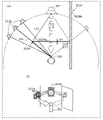
- FIG. 3 is a diagram for explaining how the listener hears sound when there is an obstacle between the sound source and the listener.
- FIG. 3(a) is a top plan view of the positional relationship between the sound source and the listener in the virtual space.
- FIG. 3B is a diagram three-dimensionally showing the positional relationship between the sound source and the listener in the virtual space.
- FIG. 4 is a diagram for explaining a first example of processing for generating a virtual sound source when there is an obstacle between the sound source and the listener.
- FIG. 4(a) is a top plan view of the positional relationship between the sound source and the listener in the virtual space.
- (b) of FIG. 4 is a diagram three-dimensionally showing the positional relationship between the sound source and the listener in the virtual space.
- the generation unit 103 of the sound reproduction device 100 has a sound source 301 that corresponds to the sound source 301 from the listening position of the listener 302 to both ends of the obstacle 303, respectively, in order to reproduce the diffracted sound in a simple manner.
- Two virtual sound sources 311 and 312 are generated that are located in the vicinity of two virtual sound source directions 351 and 352 .
- a virtual sound source direction 351 is a direction indicated by a straight line passing through the listener 302 and one horizontal end 303 a of the obstacle 303 .
- a virtual sound source direction 352 is a direction indicated by a straight line passing through the listener 302 and the other horizontal end 303 b of the obstacle 303 .
- One end 303a and the other end 303b of the obstacle 303 in the horizontal direction are the same as the ends in the horizontal direction when the listener 302 looks at the obstacle 303.
- FIG. Since the one end 303a and the other end 303b are on the shortest path along which the sound is diffracted and propagated when the obstacle 303 is placed, they may also be called diffraction points hereinafter.
- the length of the shortest propagation path L11 of the sound from the sound source 301 propagating on the left side of the obstacle 303 and the shortest propagation path L12 of the sound from the sound source 301 propagating on the right side of the obstacle 303 are shown. This is an example in which the lengths of are equal to each other.
- the propagation paths L11 and L12 are indicated by thick broken lines in FIG. 4(a). More specifically, the length from the sound source 301 to the one end 303a on the propagation path L11 is equal to the length from the sound source 301 to the other end 303b on the propagation path L12. and the length from the other end 303b of the propagation path L12 to the listening position of the listener 302 are equal to each other.
- the virtual sound sources 311 and 312 to be generated are arranged at positions having equal distances from the listening position of the listener 302 (that is, positions on circles indicated by dashed lines). Since the propagation path L11 and the propagation path L12 have the same length, the sound pressure levels of the virtual sound sources 311 and 312 are determined to be the same. Note that when the lengths of the propagation paths L11 and L12 are different from each other, the sound pressure levels of the virtual sound sources 311 and 312 are determined to be different from each other. The sound pressure levels of the sound sources 311, 312 may be determined.
- FIG. 5 is a diagram for explaining a second example of processing for generating a virtual sound source when there is an obstacle between the sound source and the listener.
- FIG. 5(a) is a top plan view of the positional relationship between the sound source and the listener in the virtual space.
- FIG. 5(b) is a diagram three-dimensionally showing the positional relationship between the sound source and the listener in the virtual space.
- the obstacle 303A in the second example differs in width (thickness) in the direction facing the sound source 301 from the listener 302 compared to the obstacle 303 in the first example.
- a width D2 of the obstacle 303A is longer than a width D1 of the obstacle 303A.
- the generation unit 103 of the sound reproduction device 100 generates an obstacle from the listening position of the listener 302 instead of the sound source 301 in order to easily reproduce the diffracted sound, as in the first example.
- Two virtual sound sources 311a and 312a are generated which are placed in close proximity on two virtual sound source directions 351 and 352 respectively corresponding to both ends of the object 303A.
- the virtual sound source direction 351 is a direction indicated by a straight line passing through the listener 302 and one horizontal end 303Aa of the obstacle 303A.
- the virtual sound source direction 352 is a direction indicated by a straight line passing through the listener 302 and the other horizontal end 303Ab of the obstacle 303A.
- the length of the shortest propagation path L21 of the sound from the sound source 301 propagating on the left side of the obstacle 303A and the shortest propagation path L22 of the sound from the sound source 301 propagating on the right side of the obstacle 303A An example is shown where the lengths of are equal.
- the propagation paths L22, L22 are indicated by thick dashed lines in FIG. 5(a). More specifically, the length from the sound source 301 to the one end 303Aa on the propagation path L21 is equal to the length from the sound source 301 to the other end 303Ab on the propagation path L22. Also, the length from one end 303Aa of the propagation path L21 to the listening position of the listener 302 and the length from the other end 303Ab of the propagation path L22 to the listening position of the listener 302 are equal to each other. Therefore, the generated virtual sound sources 311a and 312a are arranged at positions having equal distances from the listening position of the listener 302 (that is, positions on the circle indicated by the dashed line).
- the circle indicated by the dashed line is a circle whose radius is the distance from the listening position of the listener 302 to the sound source 301.
- the radius is not limited to this, and the radius is longer than the distance from the listening position to the sound source 301. , or a circle whose radius is shorter than the distance from the listening position to the sound source 301 . Since the propagation path L11 and the propagation path L12 have the same length, the sound pressure levels of the virtual sound sources 311a and 312a are determined to be the same.
- the sound pressure levels of the virtual sound sources 311 and 312 are determined to be different from each other. Sound pressure levels of the sound sources 311a, 312a may be determined.
- propagation path L21 in the second example is equal to propagation path L11 in the first example. longer than Therefore, the generating unit 103 generates the virtual sound sources 311a and 312a at positions farther from the listening position of the listener 302 in the respective virtual sound source directions 351 and 352 than the positions of the virtual sound sources 311 and 312 in the first example. That is, when the diffraction point with the obstacle 303 and the diffraction point with the obstacle 303A are the same, the generation unit 103 creates a straight line passing through the listening position of the listener 302 and the diffraction point. The sound pressure level of the sound heard by the listener 302 from the virtual sound source directions 351 and 352 is determined so as to decrease as the length of the propagation path increases.
- the generator 103 may adjust the positions of the virtual sound sources 311a and 312a so that the longer the propagation path, the farther they are from the listening position.
- the sound pressure level of the sound heard by the listener 302 from the virtual sound source directions 351 and 352 indicated by straight lines passing through the listening position of the listener 302 and the diffraction point becomes smaller as the length of the propagation path becomes longer. is determined by In this way, the generation unit 103 adjusts the sound pressure level of the sound heard by the listener 302 by adjusting the distances to the positions of the virtual sound sources 311a and 312a to be generated, using the listening position of the listener 302 as a reference.
- the generation unit 103 may adjust the sound pressure levels of the sounds emitted from the virtual sound sources 311a and 312a such that the longer the propagation path length, the lower the sound pressure level. For example, the generating unit 103 calculates the sound pressure level gain of the sounds emitted from the virtual sound sources 311a and 312a by the ratio L11/L21 obtained by dividing the length of the propagation path L11 by the length of the propagation path L21. may be determined by multiplying by the sound pressure level gain of the sound emitted from the virtual sound sources 311 and 312 .
- the generation unit 103 calculates the sound pressure level gain of the sounds emitted from the virtual sound sources 311a and 312a by the ratio D1/D2 obtained by dividing the width D1 of the obstacle 303 by the width D2 of the obstacle 303A. may be determined by multiplying by the sound pressure level gain of the sound emitted from the virtual sound sources 311 and 312 .
- FIG. 6 is a diagram for explaining a third example of processing for generating a virtual sound source when there is an obstacle between the sound source and the listener.
- FIG. 6(a) is a top plan view of the positional relationship between the sound source and the listener in the virtual space.
- FIG. 6(b) is a diagram three-dimensionally showing the positional relationship between the sound source and the listener in the virtual space.
- the third example is the same scene as the second example. That is, in the third example, the size and position of the obstacle 303A are the same as in the second example, and the listening positions of the sound source 301 and the listener 302 are also the same as in the second example.
- the generator 103 may determine the number of virtual sound sources according to the length of the propagation path. Specifically, the generation unit 103 may generate a plurality of virtual sound sources 311b and a plurality of virtual sound sources 312b so that the number of virtual sound sources increases as the length of the propagation path increases. The generation unit 103 generates a plurality (three in the example of FIG. 6) of virtual sound sources 311b and a plurality of (three in the example of FIG. Generate.
- the angular range near the direction may be, for example, an angular range of ⁇ 30 degrees or an angular range of ⁇ 45 degrees from the reference direction.
- the plurality of virtual sound sources may be arranged at positions within an angular range near the reference direction, and may not be arranged on the reference direction. may not be arranged so as to include the reference direction.
- the fact that the distribution range of a plurality of virtual sound sources is arranged so as to include the reference direction means that the plurality of virtual sound sources are arranged so as to straddle the reference direction.
- a plurality of virtual sound sources are arranged such that one of one or more line segments formed by connecting the virtual sound sources intersects the reference direction. For example, when the ratio L21/L11 obtained by dividing the length of the propagation path L21 by the length of the propagation path L11 is smaller than the first threshold, the generator 103 determines the number of virtual sound sources to be one.
- the generation unit 103 may determine the number of virtual sound sources to be two. Moreover, the generation unit 103 may determine the number of virtual sound sources to be three when the ratio L21/L11 is greater than the second threshold.
- the generation unit 103 may combine the second example and the third example to arrange a plurality of virtual sound sources.
- the generation unit 103 may determine both the sound pressure level of the sound heard by the listener from the virtual sound source directions 351 and 352 and the number of virtual sound sources to be generated, according to the length of the propagation path.
- the generating unit 103 may further determine the frequency characteristics of the sound emitted from the generated virtual sound source. That is, the generation unit 103 may determine the frequency characteristics of the sound according to the length of the propagation path in addition to the second example, or determine the sound frequency characteristic according to the length of the propagation path in addition to the third example. may be determined, or the frequency characteristic of sound may be determined according to the length of the propagation path in addition to the combination of the second example and the third example. Further, the generation unit 103 generates frequency characteristics of sounds emitted from the virtual sound sources 311 and 312 of the first example according to the length of the propagation path, without performing the processes of the second example and the third example. may decide.
- FIG. 7 is a graph showing a first example of adjustment processing of frequency characteristics of sound emitted from a virtual sound source.
- FIG. 8 is a graph showing a second example of adjustment processing of frequency characteristics of sound emitted from a virtual sound source.
- the generation unit 103 generates the frequency characteristics of the sound emitted from the virtual sound source such that the longer the propagation path, the higher the sound pressure level in the high frequency band than the sound pressure level in the low frequency band. may be determined to be smaller than .
- the generation unit 103 may determine the frequency characteristic such that the longer the propagation path length, the lower the sound pressure level in the high frequency band of the frequency characteristic. Further, the generation unit 103 may determine the frequency characteristic such that the longer the propagation path length, the higher the sound pressure level in the low frequency band of the frequency characteristic.
- the generation unit 103 determines the frequency characteristics so that the longer the propagation path length, the lower the sound pressure level in the high frequency band of the frequency characteristics and the higher the sound pressure level in the low frequency band of the frequency characteristics. may Further, as shown in FIG. 8, the generation unit 103 determines the frequency characteristics such that the longer the propagation path, the wider the bandwidth of the high-frequency band that relatively reduces the sound pressure level.
- the method of generating a virtual sound source when two propagation paths sandwiching an obstacle are formed has been described.
- the virtual sound source is arranged in each of two virtual sound source directions 351, 352 corresponding to two propagation paths.
- FIG. 9 is a diagram for explaining a fourth example of processing for generating a virtual sound source when there is an obstacle between the sound source and the listener.
- FIG. 9(a) is a plan view showing the positional relationship between the sound source and the listener in the virtual space.
- FIG. 9(b) is a diagram three-dimensionally showing the positional relationship between the sound source and the listener in the virtual space.
- the obstacle 303B in the fourth example differs from the obstacle 303 in the first example in that it has a wall-shaped second portion 303Bb arranged on one side of the sound source 301 and the listener 302.
- the obstacle 303B is connected to and continuous with a first portion 303Ba having the same configuration as the obstacle 303 arranged between the sound source 301 and the listener 302, and is connected to the first portion 303Ba. and a second portion 303Bb arranged on the right side.
- the right side of the sound source 301 and the listener 302 is one side of the first portion 303Ba.
- the second portion 303Bb is arranged in a direction intersecting the first portion 303Ba, that is, in the direction of a straight line connecting the sound source 301 and the listener 302. FIG.
- the obstacle 303B in the fourth example has the second portion 303Bb, sound from the sound source 301 is blocked by the second portion 303Bb of the obstacle 303B. Therefore, one propagation path L11 for the sound from the sound source 301 to propagate avoiding the obstacle 303B is formed only on one side of the obstacle 303B.
- the generation unit 103 generates a plurality of virtual sound sources 311b so as to be arranged only in one virtual sound source direction 351 corresponding to one propagation path L11.
- the case where one propagation path is formed only on one side of the obstacle means that the obstacle is connected to the first portion arranged between the sound source 301 and the listener 302 and connected to the first portion. and a second portion arranged to one side of at least one of the sound source 301 and the listener 302 .
- FIG. 10 is a diagram for explaining a first example of obstacle detection processing.
- FIG. 10 is a top plan view of the positional relationship between the sound source and the listener in the virtual space.
- FIG. 10 shows a rectangular structure 363 when viewed from above. That is, the structure 363 has four corners 363a to 363d when viewed from above, and the structure 363 has four sides connecting the four corners 363a to 363d. Since the positions of the four corners 363 a to 363 d are indicated by spatial information, the detection unit 102 detects whether the line segment 364 connecting the listening positions of the sound source 361 and the listener 362 is one of the four sides of the structure 363 . It is determined whether or not they intersect or touch any of the four corners 363a to 363d. If the detection unit 102 determines that the line segment 364 intersects any of the four sides of the structure 363 or touches any of the four corners 363a to 363d, it detects the structure 363 as an obstacle.
- the detection unit 102 detects two corners 363c and 363d at both ends of a side where a point 363f closer to the listener 362 exists among points 363e and 363f where the line segment 364 intersects the four sides as diffraction points. may be detected as Alternatively, the detection unit 102 detects the two corners 363c on the two outermost line segments among the four line segments connecting the listening position of the listener 362 and the four corners 363a to 363d. , 363d may be detected as diffraction spots.
- FIG. 11 is a diagram for explaining a second example of obstacle detection processing.
- FIG. 11 is a top plan view of the positional relationship between the sound source and the listener in the virtual space.
- Fig. 11 shows a hexagonal structure 373 when viewed from above. That is, the structure 373 has six corners 373a to 373f when viewed from above, and the structure 373 has six sides connecting the six corners 373a to 373f. Since the positions of the six corners 373a to 373f are indicated by spatial information, the detection unit 102 detects whether the line segment 374 connecting the listening positions of the sound source 371 and the listener 372 is one of the six sides of the structure 373. It is determined whether or not they intersect or touch any of the six corners 373a to 373f. If the detection unit 102 determines that the line segment 374 intersects any of the six sides of the structure 373 or touches any of the six corners 373a to 373f, it detects the structure 373 as an obstacle.
- the detection unit 102 detects two corners 373d and 373e at both ends of the side where the point 373h closer to the listener 372 exists among the points 373g and 373h where the line segment 374 intersects the four sides as diffraction points. may be detected as Alternatively, the detection unit 102 detects two corners 373c on the two outermost line segments among the six line segments connecting the listening position of the listener 372 and each of the 64 corners 373a to 373f. , 373e may be detected as diffraction spots.
- obstacles are detected using sides connecting the corners of polygonal obstacles. is not limited to the side connecting , but may be a side connecting arbitrary points set on the surface of the obstacle.
- FIG. 12 is a flowchart showing an example of the operation of the sound reproduction device.
- the sound reproduction device 100 acquires spatial information (S11).
- Spatial information is information for reproducing a virtual space.
- a virtual space includes a structure arranged in the virtual space and a sound source.
- the sound reproduction device 100 identifies the listening position of the listener in the virtual space (S12).
- the sound reproduction device 100 generates one or more virtual sound sources (S13).
- One or more virtual sound sources are generated in one or more virtual sound source directions from the listening position to one or more ends of the structure when a structure is placed between the sound source in the virtual space and the listening position. are placed in the vicinity of
- the sound reproduction device 100 reproduces the generated one or more virtual sound sources, and outputs the obtained audio stream to the terminal 200 (S14).
- Sound reproduction device 100 acquires spatial information for reproducing a virtual space.
- a virtual space includes a structure arranged in the virtual space and a sound source.
- the sound reproduction device 100 identifies the listening position of the listener in the virtual space.
- the sound reproduction device 100 generates one or more virtual sound sources from the listening position to one or more ends of the structure.
- One or more virtual sound sources are generated that are placed in directional proximity.
- One or more virtual sound sources are determined based on the length of the propagation path through which the sound from the sound source reaches the listener and which avoids the structure.
- the above determination includes (i) the sound pressure level of sounds heard by the listener from the direction of one or more virtual sources, (ii) the number of one or more virtual sources, and (iii) the number of sound emitted from the one or more virtual sources. frequency characteristics of the sound are determined.
- a virtual space is generated. To reproduce sound heard by a listener when a structure is placed between the sound source and the listener. Therefore, the processing load required for stereophonic reproduction can be reduced.
- the sound pressure level of sound emitted from one or more virtual sound sources is adjusted so that the sound pressure level decreases as the length of the propagation path increases. is determined by That is, the sound reproduction device 100 can generate one or more virtual sound sources such that the sound pressure level of the sound is attenuated as the length of the propagation path increases. Therefore, it is possible to reduce the processing load required to reproduce stereophonic sound, and to reproduce appropriate stereophonic sound that does not affect the listener's impression of the sound before and after placing multiple virtual sound sources in place of the source. can do.
- the sound pressure level is determined by adjusting the positions of one or more virtual sound sources such that the longer the propagation path length, the farther away from the listening position. be done. That is, the sound reproduction device 100 can generate one or more virtual sound sources whose sound pressure levels are determined according to the length of the propagation path. Therefore, it is possible to reduce the processing load required to reproduce stereophonic sound, and to reproduce appropriate stereophonic sound that does not affect the listener's impression of the sound before and after placing multiple virtual sound sources in place of sound sources. can do.
- the number of one or more virtual sound sources is determined so as to increase as the length of the propagation path increases. Therefore, it is possible to generate one or more virtual sound sources that are determined such that the longer the propagation path, the wider the sound due to the influence of diffraction. Therefore, it is possible to reduce the processing load required to reproduce stereophonic sound, and to reproduce appropriate stereophonic sound that does not affect the listener's impression of the sound before and after placing multiple virtual sound sources in place of sound sources. can do.
- the frequency characteristics are such that the longer the propagation path length, the lower the sound pressure level in the high frequency band relative to the sound pressure level in the low frequency band. It is determined. Therefore, it is possible to generate one or more virtual sound sources that are determined such that the longer the propagation path length is, the more the sound pressure level in the high frequency band is reduced due to the influence of diffraction. Therefore, it is possible to reduce the processing load required to reproduce stereophonic sound, and to reproduce appropriate stereophonic sound that has little effect on the listener's impression of the sound before and after placing multiple virtual sound sources in place of sound sources. can do.
- the frequency characteristics are adjusted such that the longer the propagation path length, the wider the bandwidth of the high frequency band that relatively reduces the sound pressure level. . Therefore, it is possible to generate one or more virtual sound sources that are determined such that the longer the propagation path length is, the more the sound pressure level in the high frequency band is reduced due to the influence of diffraction. Therefore, it is possible to reduce the processing load required to reproduce stereophonic sound, and to reproduce appropriate stereophonic sound that does not affect the listener's impression of the sound before and after placing multiple virtual sound sources in place of sound sources. can do.
- sound reproduction device 100 when two propagation paths sandwiching a structure are formed, one or more virtual sound sources are generated in two virtual sound source directions corresponding to the two propagation paths. placed. According to this, since one or more virtual sound sources corresponding to each of the two propagation paths are arranged, the impression of the sound heard by the listener can be affected before and after placing a plurality of virtual sound sources instead of sound sources. Less suitable stereophonic sound can be reproduced.
- one or more virtual sound sources are generated in only one virtual sound source direction corresponding to one propagation path. placed in Also, the number of one or more virtual sound sources is plural. According to this, when one of two propagation paths is blocked, a plurality of virtual sound sources are arranged so that sound spreads due to the effect of diffraction occurring in one propagation path. Therefore, it is possible to reproduce appropriate stereophonic sound that does not affect the impression of the sound heard by the listener before and after arranging a plurality of virtual sound sources instead of sound sources.
- the sound reproduction device 100 adjusts one or more virtual sound sources to be generated according to the length of the propagation path. Specifically, the sound reproduction device 100 measures the sound pressure level of sounds heard by the listener from the directions of one or more virtual sound sources, the number of one or more virtual sound sources, and the volume of sounds emitted from one or more virtual sound sources. Although at least one of the frequency characteristics (hereinafter referred to as a virtual sound source parameter) is adjusted, the present invention is not limited to this.
- the sound reproduction device 100 associates a plurality of positional relationships each indicating a presupposed relationship between a sound source, a structure, and a listening position, and parameters of a virtual sound source calculated in advance corresponding to the plurality of positional relationships.
- Relational information such as a table that has been used is stored in memory. Then, the sound reproduction device 100 may determine the parameters of the virtual sound source linked with the positional relationship corresponding to the acquired listening position by referring to the relationship information. In other words, the sound reproduction device 100 does not have to calculate the virtual sound source parameters in real time according to the listening position, and may specify the virtual sound source parameters calculated and determined in advance from the memory. This makes it possible to further reduce the processing load for generating the virtual sound source.
- the terminal 200 is configured to include the detection unit 203, the input reception unit 204, the display unit 205, and the audio output unit 206. , the input receiving unit 204, the display unit 205, and the audio output unit 206.
- Each device in the above embodiment is specifically a computer system composed of a microprocessor, ROM, RAM, hard disk unit, display unit, keyboard, mouse, and the like.
- a computer program is recorded in the RAM or hard disk unit.
- Each device achieves its function by the microprocessor operating according to the computer program.
- the computer program is constructed by combining a plurality of instruction codes indicating instructions to the computer in order to achieve a predetermined function.
- a system LSI is an ultra-multifunctional LSI manufactured by integrating multiple components on a single chip. Specifically, it is a computer system that includes a microprocessor, ROM, RAM, etc. . A computer program is recorded in the RAM. The system LSI achieves its functions by the microprocessor operating according to the computer program.
- each part of the constituent elements constituting each of the devices described above may be individually integrated into one chip, or may be integrated into one chip so as to include part or all of them.
- system LSI may also be called IC, LSI, super LSI, or ultra LSI depending on the degree of integration.
- the method of circuit integration is not limited to LSI, and may be realized by a dedicated circuit or a general-purpose processor.
- An FPGA Field Programmable Gate Array
- a reconfigurable processor that can reconfigure the connections and settings of the circuit cells inside the LSI may be used.
- the IC card or module is a computer system composed of a microprocessor, ROM, RAM and the like.
- the IC card or the module may include the super multifunctional LSI.
- the IC card or the module achieves its function by the microprocessor operating according to the computer program. This IC card or this module may be tamper resistant.
- the present disclosure may be the method shown above. Moreover, it may be a computer program for realizing these methods by a computer, or it may be a digital signal composed of the computer program.
- the present disclosure includes a computer-readable recording medium for the computer program or the digital signal, such as a flexible disk, hard disk, CD-ROM, MO, DVD, DVD-ROM, DVD-RAM, BD (Blu-ray (Registered Trademark) Disc), semiconductor memory, or the like. Moreover, it may be the digital signal recorded on these recording media.
- a computer-readable recording medium for the computer program or the digital signal such as a flexible disk, hard disk, CD-ROM, MO, DVD, DVD-ROM, DVD-RAM, BD (Blu-ray (Registered Trademark) Disc), semiconductor memory, or the like.
- BD Blu-ray (Registered Trademark) Disc
- semiconductor memory or the like.
- it may be the digital signal recorded on these recording media.
- the computer program or the digital signal may be transmitted via an electric communication line, a wireless or wired communication line, a network represented by the Internet, data broadcasting, or the like.
- the present disclosure may also be a computer system comprising a microprocessor and memory, the memory storing the computer program, and the microprocessor operating according to the computer program.
- the present disclosure can be used for a sound reproduction method, a sound reproduction device, a program, etc. that can reduce the processing load required for reproducing stereophonic sound.
- sound reproduction system 100 sound reproduction device 101 acquisition unit 102 detection unit 103 generation unit 104 rendering unit 105 communication unit 200 terminal 201 communication unit 202 control unit 203 detection unit 204 input reception unit 205 display unit 206 audio output unit 300 controllers 301 and 361 , 371 sound sources 302, 362, 372 listeners 303, 303A, 303B obstacles 303Ba first portion 303Bb second portion 303a one end 303b other end 311, 311a, 311b, 312, 312a, 312b virtual sound sources 363, 373 structure 351, 352 virtual sound source direction
Landscapes
- Physics & Mathematics (AREA)
- Engineering & Computer Science (AREA)
- Acoustics & Sound (AREA)
- Signal Processing (AREA)
- Health & Medical Sciences (AREA)
- Otolaryngology (AREA)
- General Health & Medical Sciences (AREA)
- Stereophonic System (AREA)
Priority Applications (5)
| Application Number | Priority Date | Filing Date | Title |
|---|---|---|---|
| JP2023514574A JPWO2022220102A1 (https=) | 2021-04-12 | 2022-03-29 | |
| EP22788027.5A EP4325887A4 (en) | 2021-04-12 | 2022-03-29 | SOUND REPRODUCTION METHOD, SOUND REPRODUCTION DEVICE, AND PROGRAM |
| CN202280027353.3A CN117157994A (zh) | 2021-04-12 | 2022-03-29 | 音响再现方法、音响再现装置和程序 |
| KR1020237034071A KR20230169964A (ko) | 2021-04-12 | 2022-03-29 | 음향 재생 방법, 음향 재생 장치, 및, 프로그램 |
| US18/373,484 US20240022854A1 (en) | 2021-04-12 | 2023-09-27 | Sound reproduction method, sound reproduction device, and recording medium |
Applications Claiming Priority (4)
| Application Number | Priority Date | Filing Date | Title |
|---|---|---|---|
| US202163173637P | 2021-04-12 | 2021-04-12 | |
| US63/173,637 | 2021-04-12 | ||
| JP2022-024143 | 2022-02-18 | ||
| JP2022024143 | 2022-02-18 |
Related Child Applications (1)
| Application Number | Title | Priority Date | Filing Date |
|---|---|---|---|
| US18/373,484 Continuation US20240022854A1 (en) | 2021-04-12 | 2023-09-27 | Sound reproduction method, sound reproduction device, and recording medium |
Publications (1)
| Publication Number | Publication Date |
|---|---|
| WO2022220102A1 true WO2022220102A1 (ja) | 2022-10-20 |
Family
ID=83640637
Family Applications (1)
| Application Number | Title | Priority Date | Filing Date |
|---|---|---|---|
| PCT/JP2022/015445 Ceased WO2022220102A1 (ja) | 2021-04-12 | 2022-03-29 | 音響再生方法、音響再生装置、及び、プログラム |
Country Status (5)
| Country | Link |
|---|---|
| US (1) | US20240022854A1 (https=) |
| EP (1) | EP4325887A4 (https=) |
| JP (1) | JPWO2022220102A1 (https=) |
| KR (1) | KR20230169964A (https=) |
| WO (1) | WO2022220102A1 (https=) |
Cited By (1)
| Publication number | Priority date | Publication date | Assignee | Title |
|---|---|---|---|---|
| US12520099B2 (en) | 2023-04-11 | 2026-01-06 | Toyota Jidosha Kabushiki Kaisha | Information processing apparatus and method |
Citations (4)
| Publication number | Priority date | Publication date | Assignee | Title |
|---|---|---|---|---|
| JP2005208166A (ja) | 2004-01-20 | 2005-08-04 | Yamaha Corp | 音響シミュレーション装置及びそのプログラム |
| JP2013201577A (ja) * | 2012-03-23 | 2013-10-03 | Shimizu Corp | 立体音響計算方法、装置、プログラム、記録媒体および立体音響提示システムならびに仮想現実空間提示システム |
| JP2014226201A (ja) * | 2013-05-20 | 2014-12-08 | 株式会社スクウェア・エニックス | ビデオゲーム処理装置、およびビデオゲーム処理プログラム |
| US20200348387A1 (en) * | 2018-05-29 | 2020-11-05 | Tencent Technology (Shenzhen) Company Limited | Sound source determining method and apparatus, and storage medium |
Family Cites Families (3)
| Publication number | Priority date | Publication date | Assignee | Title |
|---|---|---|---|---|
| WO2000045619A1 (en) * | 1999-01-28 | 2000-08-03 | Sony Corporation | Virtual sound source device and acoustic device comprising the same |
| US10251013B2 (en) * | 2017-06-08 | 2019-04-02 | Microsoft Technology Licensing, Llc | Audio propagation in a virtual environment |
| WO2019066348A1 (ko) * | 2017-09-28 | 2019-04-04 | 가우디오디오랩 주식회사 | 오디오 신호 처리 방법 및 장치 |
-
2022
- 2022-03-29 WO PCT/JP2022/015445 patent/WO2022220102A1/ja not_active Ceased
- 2022-03-29 KR KR1020237034071A patent/KR20230169964A/ko active Pending
- 2022-03-29 JP JP2023514574A patent/JPWO2022220102A1/ja active Pending
- 2022-03-29 EP EP22788027.5A patent/EP4325887A4/en active Pending
-
2023
- 2023-09-27 US US18/373,484 patent/US20240022854A1/en active Pending
Patent Citations (4)
| Publication number | Priority date | Publication date | Assignee | Title |
|---|---|---|---|---|
| JP2005208166A (ja) | 2004-01-20 | 2005-08-04 | Yamaha Corp | 音響シミュレーション装置及びそのプログラム |
| JP2013201577A (ja) * | 2012-03-23 | 2013-10-03 | Shimizu Corp | 立体音響計算方法、装置、プログラム、記録媒体および立体音響提示システムならびに仮想現実空間提示システム |
| JP2014226201A (ja) * | 2013-05-20 | 2014-12-08 | 株式会社スクウェア・エニックス | ビデオゲーム処理装置、およびビデオゲーム処理プログラム |
| US20200348387A1 (en) * | 2018-05-29 | 2020-11-05 | Tencent Technology (Shenzhen) Company Limited | Sound source determining method and apparatus, and storage medium |
Non-Patent Citations (1)
| Title |
|---|
| See also references of EP4325887A4 |
Cited By (1)
| Publication number | Priority date | Publication date | Assignee | Title |
|---|---|---|---|---|
| US12520099B2 (en) | 2023-04-11 | 2026-01-06 | Toyota Jidosha Kabushiki Kaisha | Information processing apparatus and method |
Also Published As
| Publication number | Publication date |
|---|---|
| US20240022854A1 (en) | 2024-01-18 |
| EP4325887A1 (en) | 2024-02-21 |
| KR20230169964A (ko) | 2023-12-18 |
| JPWO2022220102A1 (https=) | 2022-10-20 |
| EP4325887A4 (en) | 2024-09-25 |
Similar Documents
| Publication | Publication Date | Title |
|---|---|---|
| TWI838554B (zh) | 具有用於控制擴展實境體驗之音訊呈現之使用者介面之裝置及非暫時性電腦可讀儲存媒體及其方法 | |
| US11146905B2 (en) | 3D audio rendering using volumetric audio rendering and scripted audio level-of-detail | |
| US10397728B2 (en) | Differential headtracking apparatus | |
| US9756444B2 (en) | Rendering audio using speakers organized as a mesh of arbitrary N-gons | |
| JP7667187B2 (ja) | モバイル周辺デバイスに対する空間化されたオーディオ | |
| US20150264502A1 (en) | Audio Signal Processing Device, Position Information Acquisition Device, and Audio Signal Processing System | |
| JP2011521511A (ja) | 拡張現実を強化した音声 | |
| KR20160012204A (ko) | 믹싱 데스크, 사운드 신호 생성기, 사운드 신호를 제공하기 위한 방법 및 컴퓨터 프로그램 | |
| KR20070119542A (ko) | 음상 제어 장치 및 음상 제어 방법 | |
| US11627427B2 (en) | Enabling rendering, for consumption by a user, of spatial audio content | |
| US11070933B1 (en) | Real-time acoustic simulation of edge diffraction | |
| CN113632505B (zh) | 装置、方法、声音系统 | |
| US11302339B2 (en) | Spatial sound reproduction using multichannel loudspeaker systems | |
| US20240323607A1 (en) | Loudspeaker system for arbitrary sound direction rendering | |
| US20260025631A1 (en) | Information processing method, information processing device, and recording medium | |
| WO2022220102A1 (ja) | 音響再生方法、音響再生装置、及び、プログラム | |
| US10735885B1 (en) | Managing image audio sources in a virtual acoustic environment | |
| US20240284137A1 (en) | Location Based Audio Rendering | |
| WO2023199817A1 (ja) | 情報処理方法、情報処理装置、音響再生システム、及び、プログラム | |
| CN117157994A (zh) | 音响再现方法、音响再现装置和程序 | |
| KR102519156B1 (ko) | 무선 헤드셋을 사용해 휴대 기기 위치를 알려주는 방법 및 시스템 | |
| CN117178570A (zh) | 信息处理方法、信息处理装置和程序 | |
| KR20190091824A (ko) | 바이노럴 스테레오 오디오 생성 방법 및 이를 위한 장치 | |
| KR102119241B1 (ko) | 멀티 채널 비주얼라이제이션 방법 및 이를 위한 프로그램 | |
| KR102358514B1 (ko) | 다극 음향 객체를 이용한 음향 제어 장치 및 그 방법 |
Legal Events
| Date | Code | Title | Description |
|---|---|---|---|
| 121 | Ep: the epo has been informed by wipo that ep was designated in this application |
Ref document number: 22788027 Country of ref document: EP Kind code of ref document: A1 |
|
| WWE | Wipo information: entry into national phase |
Ref document number: 202347067874 Country of ref document: IN |
|
| WWE | Wipo information: entry into national phase |
Ref document number: 2023514574 Country of ref document: JP |
|
| WWE | Wipo information: entry into national phase |
Ref document number: 2022788027 Country of ref document: EP |
|
| NENP | Non-entry into the national phase |
Ref country code: DE |
|
| ENP | Entry into the national phase |
Ref document number: 2022788027 Country of ref document: EP Effective date: 20231113 |