WO2022219981A1 - 磁歪材料の製造方法、磁歪材料およびエネルギー変換部材の製造方法 - Google Patents
磁歪材料の製造方法、磁歪材料およびエネルギー変換部材の製造方法 Download PDFInfo
- Publication number
- WO2022219981A1 WO2022219981A1 PCT/JP2022/011109 JP2022011109W WO2022219981A1 WO 2022219981 A1 WO2022219981 A1 WO 2022219981A1 JP 2022011109 W JP2022011109 W JP 2022011109W WO 2022219981 A1 WO2022219981 A1 WO 2022219981A1
- Authority
- WO
- WIPO (PCT)
- Prior art keywords
- alloy
- manufacturing
- magnetostrictive
- magnetostrictive material
- plane
- Prior art date
- Legal status (The legal status is an assumption and is not a legal conclusion. Google has not performed a legal analysis and makes no representation as to the accuracy of the status listed.)
- Ceased
Links
Images








Classifications
-
- B—PERFORMING OPERATIONS; TRANSPORTING
- B22—CASTING; POWDER METALLURGY
- B22F—WORKING METALLIC POWDER; MANUFACTURE OF ARTICLES FROM METALLIC POWDER; MAKING METALLIC POWDER; APPARATUS OR DEVICES SPECIALLY ADAPTED FOR METALLIC POWDER
- B22F10/00—Additive manufacturing of workpieces or articles from metallic powder
- B22F10/20—Direct sintering or melting
- B22F10/25—Direct deposition of metal particles, e.g. direct metal deposition [DMD] or laser engineered net shaping [LENS]
-
- B—PERFORMING OPERATIONS; TRANSPORTING
- B22—CASTING; POWDER METALLURGY
- B22F—WORKING METALLIC POWDER; MANUFACTURE OF ARTICLES FROM METALLIC POWDER; MAKING METALLIC POWDER; APPARATUS OR DEVICES SPECIALLY ADAPTED FOR METALLIC POWDER
- B22F10/00—Additive manufacturing of workpieces or articles from metallic powder
- B22F10/20—Direct sintering or melting
- B22F10/28—Powder bed fusion, e.g. selective laser melting [SLM] or electron beam melting [EBM]
-
- B—PERFORMING OPERATIONS; TRANSPORTING
- B23—MACHINE TOOLS; METAL-WORKING NOT OTHERWISE PROVIDED FOR
- B23K—SOLDERING OR UNSOLDERING; WELDING; CLADDING OR PLATING BY SOLDERING OR WELDING; CUTTING BY APPLYING HEAT LOCALLY, e.g. FLAME CUTTING; WORKING BY LASER BEAM
- B23K15/00—Electron-beam welding or cutting
- B23K15/0046—Welding
- B23K15/0086—Welding welding for purposes other than joining, e.g. build-up welding
-
- B—PERFORMING OPERATIONS; TRANSPORTING
- B23—MACHINE TOOLS; METAL-WORKING NOT OTHERWISE PROVIDED FOR
- B23K—SOLDERING OR UNSOLDERING; WELDING; CLADDING OR PLATING BY SOLDERING OR WELDING; CUTTING BY APPLYING HEAT LOCALLY, e.g. FLAME CUTTING; WORKING BY LASER BEAM
- B23K15/00—Electron-beam welding or cutting
- B23K15/0046—Welding
- B23K15/0093—Welding characterised by the properties of the materials to be welded
-
- B—PERFORMING OPERATIONS; TRANSPORTING
- B23—MACHINE TOOLS; METAL-WORKING NOT OTHERWISE PROVIDED FOR
- B23K—SOLDERING OR UNSOLDERING; WELDING; CLADDING OR PLATING BY SOLDERING OR WELDING; CUTTING BY APPLYING HEAT LOCALLY, e.g. FLAME CUTTING; WORKING BY LASER BEAM
- B23K26/00—Working by laser beam, e.g. welding, cutting or boring
- B23K26/0006—Working by laser beam, e.g. welding, cutting or boring taking account of the properties of the material involved
-
- B—PERFORMING OPERATIONS; TRANSPORTING
- B23—MACHINE TOOLS; METAL-WORKING NOT OTHERWISE PROVIDED FOR
- B23K—SOLDERING OR UNSOLDERING; WELDING; CLADDING OR PLATING BY SOLDERING OR WELDING; CUTTING BY APPLYING HEAT LOCALLY, e.g. FLAME CUTTING; WORKING BY LASER BEAM
- B23K26/00—Working by laser beam, e.g. welding, cutting or boring
- B23K26/34—Laser welding for purposes other than joining
- B23K26/342—Build-up welding
-
- B—PERFORMING OPERATIONS; TRANSPORTING
- B33—ADDITIVE MANUFACTURING TECHNOLOGY
- B33Y—ADDITIVE MANUFACTURING, i.e. MANUFACTURING OF THREE-DIMENSIONAL [3D] OBJECTS BY ADDITIVE DEPOSITION, ADDITIVE AGGLOMERATION OR ADDITIVE LAYERING, e.g. BY 3D PRINTING, STEREOLITHOGRAPHY OR SELECTIVE LASER SINTERING
- B33Y70/00—Materials specially adapted for additive manufacturing
-
- B—PERFORMING OPERATIONS; TRANSPORTING
- B33—ADDITIVE MANUFACTURING TECHNOLOGY
- B33Y—ADDITIVE MANUFACTURING, i.e. MANUFACTURING OF THREE-DIMENSIONAL [3D] OBJECTS BY ADDITIVE DEPOSITION, ADDITIVE AGGLOMERATION OR ADDITIVE LAYERING, e.g. BY 3D PRINTING, STEREOLITHOGRAPHY OR SELECTIVE LASER SINTERING
- B33Y80/00—Products made by additive manufacturing
-
- C—CHEMISTRY; METALLURGY
- C22—METALLURGY; FERROUS OR NON-FERROUS ALLOYS; TREATMENT OF ALLOYS OR NON-FERROUS METALS
- C22C—ALLOYS
- C22C30/00—Alloys containing less than 50% by weight of each constituent
-
- C—CHEMISTRY; METALLURGY
- C22—METALLURGY; FERROUS OR NON-FERROUS ALLOYS; TREATMENT OF ALLOYS OR NON-FERROUS METALS
- C22C—ALLOYS
- C22C38/00—Ferrous alloys, e.g. steel alloys
- C22C38/10—Ferrous alloys, e.g. steel alloys containing cobalt
-
- H—ELECTRICITY
- H10—SEMICONDUCTOR DEVICES; ELECTRIC SOLID-STATE DEVICES NOT OTHERWISE PROVIDED FOR
- H10N—ELECTRIC SOLID-STATE DEVICES NOT OTHERWISE PROVIDED FOR
- H10N35/00—Magnetostrictive devices
- H10N35/01—Manufacture or treatment
-
- H—ELECTRICITY
- H10—SEMICONDUCTOR DEVICES; ELECTRIC SOLID-STATE DEVICES NOT OTHERWISE PROVIDED FOR
- H10N—ELECTRIC SOLID-STATE DEVICES NOT OTHERWISE PROVIDED FOR
- H10N35/00—Magnetostrictive devices
- H10N35/80—Constructional details
- H10N35/85—Magnetostrictive active materials
-
- B—PERFORMING OPERATIONS; TRANSPORTING
- B22—CASTING; POWDER METALLURGY
- B22F—WORKING METALLIC POWDER; MANUFACTURE OF ARTICLES FROM METALLIC POWDER; MAKING METALLIC POWDER; APPARATUS OR DEVICES SPECIALLY ADAPTED FOR METALLIC POWDER
- B22F10/00—Additive manufacturing of workpieces or articles from metallic powder
- B22F10/30—Process control
- B22F10/34—Process control of powder characteristics, e.g. density, oxidation or flowability
-
- B—PERFORMING OPERATIONS; TRANSPORTING
- B22—CASTING; POWDER METALLURGY
- B22F—WORKING METALLIC POWDER; MANUFACTURE OF ARTICLES FROM METALLIC POWDER; MAKING METALLIC POWDER; APPARATUS OR DEVICES SPECIALLY ADAPTED FOR METALLIC POWDER
- B22F10/00—Additive manufacturing of workpieces or articles from metallic powder
- B22F10/30—Process control
- B22F10/36—Process control of energy beam parameters
-
- B—PERFORMING OPERATIONS; TRANSPORTING
- B22—CASTING; POWDER METALLURGY
- B22F—WORKING METALLIC POWDER; MANUFACTURE OF ARTICLES FROM METALLIC POWDER; MAKING METALLIC POWDER; APPARATUS OR DEVICES SPECIALLY ADAPTED FOR METALLIC POWDER
- B22F10/00—Additive manufacturing of workpieces or articles from metallic powder
- B22F10/30—Process control
- B22F10/36—Process control of energy beam parameters
- B22F10/366—Scanning parameters, e.g. hatch distance or scanning strategy
-
- B—PERFORMING OPERATIONS; TRANSPORTING
- B22—CASTING; POWDER METALLURGY
- B22F—WORKING METALLIC POWDER; MANUFACTURE OF ARTICLES FROM METALLIC POWDER; MAKING METALLIC POWDER; APPARATUS OR DEVICES SPECIALLY ADAPTED FOR METALLIC POWDER
- B22F10/00—Additive manufacturing of workpieces or articles from metallic powder
- B22F10/30—Process control
- B22F10/38—Process control to achieve specific product aspects, e.g. surface smoothness, density, porosity or hollow structures
-
- B—PERFORMING OPERATIONS; TRANSPORTING
- B22—CASTING; POWDER METALLURGY
- B22F—WORKING METALLIC POWDER; MANUFACTURE OF ARTICLES FROM METALLIC POWDER; MAKING METALLIC POWDER; APPARATUS OR DEVICES SPECIALLY ADAPTED FOR METALLIC POWDER
- B22F9/00—Making metallic powder or suspensions thereof
- B22F9/02—Making metallic powder or suspensions thereof using physical processes
- B22F9/04—Making metallic powder or suspensions thereof using physical processes starting from solid material, e.g. by crushing, grinding or milling
- B22F2009/043—Making metallic powder or suspensions thereof using physical processes starting from solid material, e.g. by crushing, grinding or milling by ball milling
-
- B—PERFORMING OPERATIONS; TRANSPORTING
- B22—CASTING; POWDER METALLURGY
- B22F—WORKING METALLIC POWDER; MANUFACTURE OF ARTICLES FROM METALLIC POWDER; MAKING METALLIC POWDER; APPARATUS OR DEVICES SPECIALLY ADAPTED FOR METALLIC POWDER
- B22F3/00—Manufacture of workpieces or articles from metallic powder characterised by the manner of compacting or sintering; Apparatus specially adapted therefor ; Presses and furnaces
- B22F3/10—Sintering only
- B22F3/11—Making porous workpieces or articles
- B22F3/1103—Making porous workpieces or articles with particular physical characteristics
- B22F3/1115—Making porous workpieces or articles with particular physical characteristics comprising complex forms, e.g. honeycombs
-
- B—PERFORMING OPERATIONS; TRANSPORTING
- B23—MACHINE TOOLS; METAL-WORKING NOT OTHERWISE PROVIDED FOR
- B23K—SOLDERING OR UNSOLDERING; WELDING; CLADDING OR PLATING BY SOLDERING OR WELDING; CUTTING BY APPLYING HEAT LOCALLY, e.g. FLAME CUTTING; WORKING BY LASER BEAM
- B23K2103/00—Materials to be soldered, welded or cut
- B23K2103/02—Iron or ferrous alloys
-
- B—PERFORMING OPERATIONS; TRANSPORTING
- B23—MACHINE TOOLS; METAL-WORKING NOT OTHERWISE PROVIDED FOR
- B23K—SOLDERING OR UNSOLDERING; WELDING; CLADDING OR PLATING BY SOLDERING OR WELDING; CUTTING BY APPLYING HEAT LOCALLY, e.g. FLAME CUTTING; WORKING BY LASER BEAM
- B23K2103/00—Materials to be soldered, welded or cut
- B23K2103/02—Iron or ferrous alloys
- B23K2103/04—Steel or steel alloys
-
- B—PERFORMING OPERATIONS; TRANSPORTING
- B33—ADDITIVE MANUFACTURING TECHNOLOGY
- B33Y—ADDITIVE MANUFACTURING, i.e. MANUFACTURING OF THREE-DIMENSIONAL [3D] OBJECTS BY ADDITIVE DEPOSITION, ADDITIVE AGGLOMERATION OR ADDITIVE LAYERING, e.g. BY 3D PRINTING, STEREOLITHOGRAPHY OR SELECTIVE LASER SINTERING
- B33Y10/00—Processes of additive manufacturing
-
- B—PERFORMING OPERATIONS; TRANSPORTING
- B33—ADDITIVE MANUFACTURING TECHNOLOGY
- B33Y—ADDITIVE MANUFACTURING, i.e. MANUFACTURING OF THREE-DIMENSIONAL [3D] OBJECTS BY ADDITIVE DEPOSITION, ADDITIVE AGGLOMERATION OR ADDITIVE LAYERING, e.g. BY 3D PRINTING, STEREOLITHOGRAPHY OR SELECTIVE LASER SINTERING
- B33Y50/00—Data acquisition or data processing for additive manufacturing
- B33Y50/02—Data acquisition or data processing for additive manufacturing for controlling or regulating additive manufacturing processes
-
- C—CHEMISTRY; METALLURGY
- C22—METALLURGY; FERROUS OR NON-FERROUS ALLOYS; TREATMENT OF ALLOYS OR NON-FERROUS METALS
- C22C—ALLOYS
- C22C33/00—Making ferrous alloys
- C22C33/02—Making ferrous alloys by powder metallurgy
- C22C33/0257—Making ferrous alloys by powder metallurgy characterised by the range of the alloying elements
- C22C33/0278—Making ferrous alloys by powder metallurgy characterised by the range of the alloying elements with at least one alloying element having a minimum content above 5%
- C22C33/0285—Making ferrous alloys by powder metallurgy characterised by the range of the alloying elements with at least one alloying element having a minimum content above 5% with Cr, Co, or Ni having a minimum content higher than 5%
-
- Y—GENERAL TAGGING OF NEW TECHNOLOGICAL DEVELOPMENTS; GENERAL TAGGING OF CROSS-SECTIONAL TECHNOLOGIES SPANNING OVER SEVERAL SECTIONS OF THE IPC; TECHNICAL SUBJECTS COVERED BY FORMER USPC CROSS-REFERENCE ART COLLECTIONS [XRACs] AND DIGESTS
- Y02—TECHNOLOGIES OR APPLICATIONS FOR MITIGATION OR ADAPTATION AGAINST CLIMATE CHANGE
- Y02P—CLIMATE CHANGE MITIGATION TECHNOLOGIES IN THE PRODUCTION OR PROCESSING OF GOODS
- Y02P10/00—Technologies related to metal processing
- Y02P10/25—Process efficiency
Definitions
- the present invention relates to a method for manufacturing a magnetostrictive material, a magnetostrictive material manufactured by the manufacturing method, and a method for manufacturing an energy conversion member using the magnetostrictive material.
- the present invention has been made with a focus on such problems, and aims to provide a method for manufacturing a magnetostrictive material that can be manufactured without using a mold, and a method for manufacturing a magnetostrictive material and an energy conversion member.
- a method for producing a magnetostrictive material according to the present invention is characterized by melting raw material powder of a magnetostrictive material by a directional energy deposition method and laminating and manufacturing the melted material.
- a magnetostrictive material can be manufactured without using a mold.
- a magnetostrictive material having three-dimensional magnetic anisotropy can be produced.
- the method for manufacturing a magnetostrictive material according to the present invention may have a step of cutting the laminated magnetostrictive material in a predetermined direction.
- a magnetostrictive material having different properties depending on the cutting direction can be manufactured.
- the raw material powder is preferably made of an Fe—Co alloy.
- the raw material powder may be laminated to form a honeycomb structure. In this case, the output power density per unit volume of the produced magnetostrictive material can be increased.
- a magnetostrictive material according to the present invention is manufactured by the method for manufacturing a magnetostrictive material described above, and is characterized by having a honeycomb structure. The magnetostrictive material has an enhanced output power density per unit volume.
- a method for manufacturing an energy conversion member according to the present invention includes a magnetostrictive layer formed by melting a raw material powder of a magnetostrictive material by a directional energy deposition method and layer-molding the powder, and melting a raw powder of a soft magnetic material by a directional energy deposition method.
- One of the soft magnetic layers formed by lamination molding is laminated and joined to the other.
- a magnetostrictive material and a soft magnetic material can be manufactured without using a mold, and they can also be joined by laminating one on the other.
- a pickup coil is provided around the energy conversion member manufactured by the method for manufacturing an energy conversion member according to the present invention, an induced current can be generated in the pickup coil by the inverse magnetostriction effect of the magnetostrictive material due to vibration.
- the raw material powder of the magnetostrictive material is made of Fe--Co alloy
- the raw material powder of the soft magnetic material is made of Ni-0 to 20 mass % Fe alloy or Ni--Co alloy.
- Another method of manufacturing an energy conversion member according to the present invention is characterized by laminating and bonding a magnetostrictive layer to a soft magnetic material by melting raw material powder of a magnetostrictive material by a directional energy deposition method and laminating and molding the melted material.
- the soft magnetic material is made of an elongated plate-like Ni-0 to 20% by mass Fe alloy or Ni--Co alloy.
- the present invention it is possible to provide a method for manufacturing a magnetostrictive material, a method for manufacturing a magnetostrictive material, and a method for manufacturing an energy conversion member that can manufacture a magnetostrictive material without using a mold.
- FIG. 1 is (a) an SEM image of Fe—Co powder, and (b) explanatory diagrams of a scanning direction and a stacking direction used in a method for producing a magnetostrictive material according to an embodiment of the present invention; Magnetostriction-magnetic field curve of additively manufactured Fe—Co alloy in (a) xy plane, (b) yz plane, (c) zx plane of Example 1 of the present invention, (d) x- BH curves of additively manufactured Fe—Co alloys in the y plane, (e) the yz plane, and (f) the zx plane.
- Graph showing X-ray diffraction (XRD) patterns of (a) rolled material and laminate-manufactured alloy (300 W) (yz plane) of Example 1 of the present invention, (b) rolled material and (c) lamination Figure 10 is a graph showing the full width at half maximum (FWHM) calculated from the X-ray diffractometry pattern of the fabricated alloy (300W) (yz plane).
- Example 1 of the present invention Showing the microstructure obtained by EBSD analysis of Example 1 of the present invention, (a) rolled material, (b) alloy (300 W) (xy plane), (c) alloy (300 W) (yz plane ) kernel mean misorientation (KAM) map and inverse pole figure (IPF) map of (d) rolled material, (e) alloy (300 W) (xy plane), (f) alloy (300 W) (yz Planar) high-resolution KAM and IPF maps.
- 4 is a graph showing the relationship between laser energy density and relative density of the additively manufactured alloy of Example 1 of the present invention.
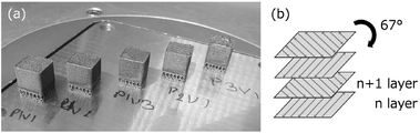
- FIG. 4 is a schematic diagram showing (a) Fe52-Co48 alloy cubes produced using various parameters in Example 3 of the present invention, (b) the scanning method used. It is a schematic diagram of a vibration energy harvesting performance test, (b) a schematic diagram of an impact energy harvesting performance test.
- FIG. 4 is a graph showing the relationship between porosity and energy density of Fe52-Co48 alloy cubes manufactured with each parameter.
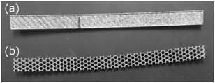
- Fig. 3 is a photograph of the external appearance of Fe52-Co48 alloy plates having (a) a fully dense structure and (b) a honeycomb structure produced using P2V1.
- graph. 4 is a graph showing power densities of Fe52-Co48 alloy plates with a fully dense structure and a honeycomb structure in an impact energy harvesting test.
- the material powder of the magnetostrictive material is melted by a laser or an electron beam using a metal 3D layered manufacturing apparatus to perform layered manufacturing.
- the power of the laser or electron beam may be varied.
- the lamination speed may be varied.
- Metal 3D additive manufacturing machines are used to additively manufacture metals by directed energy deposition (DED) methods.
- An Fe—Co alloy can be used as the raw material powder of the magnetostrictive material.
- Fe—Co alloys are low cost and can be used as magnetostrictive materials for energy harvesting and sensor applications. Fe--Co alloys exhibit moderate magnetostriction of 80-140 ppm, competitively low cost, and excellent mechanical properties.
- Fe--Co alloys can be processed into rods, plates and wires.
- a magnetostrictive material can be manufactured without using a mold. Also, a magnetostrictive material having three-dimensional magnetic anisotropy can be produced. Additionally, it can be shaped into complex shapes or structures. Post-treatments such as rolling and heat treatment that are performed after conventional manufacturing may not be performed after the additive manufacturing process. A step of cutting the laminated magnetostrictive material in a predetermined direction may be included. A magnetostrictive material having different properties depending on the cutting direction can be produced.
- the raw material powder of the magnetostrictive material is made of Fe--Co alloy, for example.
- the raw material powder of the soft magnetic material is made of, for example, Ni-0 to 20 mass % Fe alloy or Ni--Co alloy.
- Additively manufactured Fe--Co alloys have better magnetostrictive performance than hot-rolled Fe--Co alloys.
- the anisotropic energy ⁇ K1 of the Fe—Co alloy (alloy (300 W)) obtained with a laser output of 300 W is larger than that of the rolled material.
- the piezomagnetic constant d of the alloy (300 W) with respect to the yz plane is large, 340 pm/A, regardless of the magnetic field direction.
- the alloy (300W) for the yz plane has a lower lattice strain compared to the rolled material and a higher lattice strain in the ⁇ 200> plane. This means that additively manufactured alloys have far fewer lattice defects, such as dislocations, compared to rolled material. Therefore, for low piezomagnetic constants d, domain migration in the alloy is considered to be difficult.
- the piezoelectric constant d in a specific direction of the additively manufactured Fe—Co alloy is more than three times that of the rolled material. Furthermore, the elongated voids formed during additive manufacturing change the magnetostrictive performance perpendicular to these voids. Additively manufactured Fe—Co alloys have potential applications as force sensors for the Internet of Things (IoT), which need to be highly responsive.
- the raw material powder of the magnetostrictive material may be laminate-molded into a honeycomb structure. In this case, the output power density per unit volume of the produced magnetostrictive material can be increased.
- a magnetostrictive material according to an embodiment of the present invention is manufactured by the method for manufacturing a magnetostrictive material described above, and has a honeycomb structure. The magnetostrictive material has an enhanced output power density per unit volume.
- a magnetostrictive layer formed by melting raw material powder of a magnetostrictive material and laminating and molding is formed by using a metal 3D additive manufacturing apparatus. It is laminated and bonded to a soft magnetic layer which is melted by an energy deposition method and laminated. Alternatively, the soft magnetic layer is laminated and joined to the magnetostrictive layer.
- the manufactured energy conversion member is shaped into, for example, an elongated plate shape, and is used by attaching one end to a resonance generator or the like like a cantilever beam.
- a pickup is provided around the energy conversion member, and an induced current can be generated in the pickup by the inverse magnetostriction effect of the magnetostrictive material due to vibration, so that it can be used as a power generator or a sensor.
- the pickup can be composed of, for example, a coil in which the energy conversion member is arranged.
- the magnetostrictive layer may be laminated and bonded to a preliminarily prepared soft magnetic body.
- the soft magnetic material is made of, for example, an elongated plate-like Ni-0 to 20% by mass Fe alloy or Ni--Co alloy.
- a Fe30-Co70 magnetostrictive material powder with an average particle size of 120 ⁇ m or greater was produced by gas atomization.
- the metal 3D additive manufacturing equipment (DED equipment) used (“Mobile 1.0” from BeAM, France) requires particles smaller than 105 ⁇ m, ideally between 40 and 90 ⁇ m. Therefore, the starting magnetostrictive material powder was ball milled under the conditions described in Table 1 to reduce the particle size from 120 ⁇ m to 45 ⁇ m.
- the average particle size was about 45 ⁇ m, as shown in FIG. 1(a).
- the prepared magnetostrictive material powder was subjected to additive manufacturing using a metal 3D additive manufacturing apparatus (“Mobile 1.0” manufactured by BeAM, France).
- a 1 ⁇ 1 ⁇ 1 cm 3 Fe—Co alloy was fabricated on a steel plate (316 L, 1 cm thick) in a DED apparatus under controlled atmosphere (O 2 ⁇ 10 ppm, H 2 O ⁇ 150 ppm).
- the printing conditions were a hatch space of 0.56 mm, a scanning speed of 1000 mm/min and a layer thickness of 0.2 mm.
- the laser power was set at 200, 250 and 300W. corresponding to 107.1, 133.9 and 160.7 J/mm 3 respectively.
- the scanning direction and stacking direction were the y direction and the z direction, respectively (see FIG. 1(b)).
- the powder feed rate was maintained at 4 g/min for all laminated structures.
- the density of the Fe--Co alloys produced was measured by the Archimedes method. Crystal structure, orientation, and grain size were analyzed by SEM (SU-70, Hitachi) and electron backscatter diffraction (EBSD) in the xy, yz, and zx planes after ion milling (“IM4000”, Hitachi). ).
- alloy In order to measure the magnetic and magnetostrictive properties, the alloy was cut in each plane (xy, yz, zx) and ground to a width of approximately 6 ⁇ 6 mm 2 and a thickness of approximately 0.2 mm.
- the xy plane of the Fe—Co alloy obtained at 200 W hereinafter referred to as “alloy (200 W)” had many cracks during the polishing process, making measurement difficult.
- a hot rolled Fe30-Co70 alloy was also prepared for comparative measurements.
- the magnetostrictive properties and crystal structure of the layer-fabricated Fe—Co alloy were investigated by the XRD method, and saturation magnetization, remanent magnetization, and Coercivity was measured. Magnetostriction was measured by the strain gauge method using a biaxial gauge, applying a magnetic field parallel and perpendicular to each direction (xy, yz, zx planes) as in the case of EBSD. The magnetic anisotropic energy was also calculated using the results obtained by the VSM measurements.
- FIG. 2a is the result of the magnetostriction-field curve for the xy plane of the additively manufactured Fe—Co alloy.
- the initial slope of the curve for the Fe—Co alloy 250 W is higher than for the rolled alloy.
- the constitutive equation for the magnetostrictive material is given below.
- ⁇ s ⁇ +d′H (1)
- B d' ⁇ + ⁇ H (2)
- ⁇ and ⁇ are stress and strain
- B and H are magnetic flux density and strength of magnetic field
- s, d′ and ⁇ are elastic compliance coefficient, magnetoelastic constant and magnetic permeability, respectively.
- the slope of the curve indicates the piezoelectric constant d, which is a parameter directly related to the performance of the magnetostrictive element. Therefore, it is believed that the additively manufactured Fe--Co alloy exhibits better performance as a magnetostrictive element than the conventional rolled Fe--Co alloy.
- the initial gradient of the Fe—Co alloy (250 W) under the magnetic field in the y direction is larger than the initial gradient under the magnetic field in the x direction.
- the results for the Fe—Co alloy (300 W) show that increasing the power reduces the initial gradient regardless of the direction of the applied magnetic field.
- the magnitude of the magnetic field at which the magnetostriction reaches saturation is much smaller than that of the rolled material.
- a similar trend is seen for the Fe—Co alloy (300 W) under a magnetic field in the y direction.
- magnetostriction increases linearly with increasing magnetic field and does not saturate below 150 kA/m.
- the magnetostriction of Fe--Co alloy (250 W) under y-direction magnetic field is lower than that of Fe--Co alloy (250 W) under x-direction magnetic field and Fe--Co alloy (300 W) under x- and y-direction magnetic fields. .
- FIG. 2b shows similar results for the yz plane.
- the initial slope of the curve for the Fe—Co alloy (300 W) is much larger than that of the Fe—Co alloy (250 W) and the rolled material.
- the output then increases the slope of the curve.
- magnetostriction decreases with output.
- FIG. 2c shows similar results in the zx plane. Similar to the Fe--Co alloy (300 W) under the x-direction magnetic field in the xy plane, the magnetostriction of the Fe--Co alloy (300 W) under the x-direction magnetic field increases linearly with increasing magnetic field. After that, the magnetostriction gradually becomes saturated.
- Figures 2d, e, and f show the BH curves in the xy, yz, and zx planes, respectively.
- FIG. 3a shows the anisotropy energy ⁇ K1 in the xy plane of the additively manufactured Fe—Co alloy. For comparison, the results for the rolled material are also shown. The anisotropic energy ⁇ K1 of the Fe—Co alloy (300 W) is larger than that of the rolled material.
- Figures 3b and c show the results for the yz and zx planes of the additively manufactured Fe-Co alloy. In contrast to the xy plane, the anisotropy energy E in the yz plane of the Fe—Co alloy (300 W) is smaller than that of the rolled material.
- Figures 3d, e and f show the piezoelectric constant d in the xy, yz and zx planes, respectively.
- the result of the rolled material is also shown in Fig. 3d.
- the piezomagnetic constant d of the rolled material under the magnetic field in the rolling direction is about 110 pm/A.
- the magnetic field perpendicular to the rolling direction is 80 pm/A.
- the piezoelectric constant d of the Fe—Co alloy (300 W) is the largest (approximately 300 pm/A) under the x direction magnetic field, whereas the Fe—Co alloy (300 W) under the y direction magnetic field has the smallest piezoelectric constant d (approximately 40 pm/A). This is because the anisotropy energy is high.
- the value of the piezoelectric constant d of the Fe—Co alloy (300 W) is large in both the y and z directions (340 and 260 pm/A, respectively). This is because the anisotropy energy is small.
- the Fe--Co alloy (300 W) has anisotropic magnetostrictive properties in the xy plane and isotropic magnetostrictive properties in the yz plane.
- Figures 3g, h and i show the maximum piezomagnetic constant d (maximum value of the constant d) corresponding to Figures 3d, e and f, respectively.
- the value of the graph is the value of the magnetic flux density with the maximum slope.
- the maximum piezomagnetic constant d of the additively manufactured Fe—Co alloy is larger than the maximum piezomagnetic constant d of the rolled material.
- the value of the magnetic flux density at which d shows the maximum value is small in both the y and z directions on the yz plane for the Fe—Co alloy (300 W).
- Figure 4a shows the X-ray diffraction (XRD) data for the yz plane of the rolled material and alloy (300W).
- XRD X-ray diffraction
- the ⁇ 100> plane is dominant in the rolled material
- the ⁇ 110> plane is dominant in the yz plane of the alloy (300W).
- the lattice constants in the yz plane of the rolled and alloyed (300 W) are calculated from the X-ray diffraction patterns and are 0.2835 and 0.2839 nm, respectively.
- K is the form factor (Scherrer constant)
- ⁇ is the X-ray wavelength (1.5418 ⁇ for CuK ⁇ radiation)
- D is the crystal size in nanometers
- ⁇ is the peak center.
- Figures 4b and c show the FWHM ⁇ in the xy plane for the rolled material and alloy (300 W), respectively.
- the alloy (300W) (yz plane) has a lower lattice strain compared to the rolled material, and each sample has a higher lattice strain in the ⁇ 200> plane. This indicates that alloys produced by additive manufacturing have far fewer lattice defects, such as dislocations, compared to rolled material. Therefore, the low piezomagnetic constant d can be explained by making the domain movement of the alloy difficult.
- Figure 5a shows the kernel mean misorientation (KAM) and inverse pole figure (IPF) maps obtained from the EBSD analysis of the rolled material.
- KAM kernel mean misorientation
- IPF inverse pole figure
- voids are preferentially aligned in the y-direction (scanning direction) because the hatch spacing at the interface between two subsequent layers is too large.
- the deformation due to the x-direction magnetic field should be small due to the presence of voids in the y-direction, so the piezoelectric constant d under the x-direction magnetic field (see Fig. 5d) becomes larger than the piezoelectric constant d under the y-direction magnetic field. .
- These voids are believed to contribute to magnetostriction in the x direction.
- the magnetostriction in the x-direction is at the same level as the rolled material.
- the KAM map shows strong strain near grain boundaries. This y-direction strain contributes to an increase in the piezoelectric constant d under the y-direction magnetic field (see FIG. 5e) and an increase in magnetostriction in the y-direction. It can also be confirmed from the IPF map that the columnar crystal structure grows in the z direction (stacking direction).
- Table 3 summarizes the results of magnetic measurements for rolled and additively manufactured alloys (300 W).
- the alloy (300 W) exhibits a low saturation magnetization compared to the rolled material, and the saturation magnetization in the yz plane is particularly low.
- the alloy (300 W) also exhibits lower remanent magnetization and coercivity than the rolled material. This means that these samples can be used in low field sensors due to their low coercivity.
- the density of the alloy (300W) appears to be closest to the theoretical value. High input energy densities are required to obtain high relative densities. From the relationship between energy and relative density as shown in FIG. 6, it is believed that an energy density of 500 J/mm 3 will yield a fully dense alloy. Increasing energy density requires decreasing scan speed, hatch spacing, and layer thickness.
- the magnetostrictive and magnetic properties of Fe--Co alloys have been layer-fabricated using DED systems with various energy densities and their magnetostrictive and magnetic properties have been elucidated. was shown. Furthermore, voids formed during additive manufacturing (AM) increase or decrease the magnetostrictive properties of additively manufactured Fe—Co alloys depending on the direction. For the alloy (300 W) for the yz plane, the piezomagnetic constant d was large, about 340 pm/A, regardless of the magnetic field direction. This result indicates that it is at least three times higher than that of the rolled material.
- AM additive manufacturing
- the piezoelectric constant d under the x-direction magnetic field is also three times or more that of the rolled material, and the magnetostriction is approximately the same as that of the rolled material.
- the coercive force has decreased, so it is possible to apply additively manufactured Fe—Co alloys, for example, to IoT sensors with complex shapes.
- the properties of alloys produced by additive manufacturing can be further improved by controlling the structure in one direction like a single crystal.
- Fe49-Co49 magnetostrictive material powder (particle size 37-42 ⁇ m) containing a small amount of vanadium (V) was formed into a honeycomb structure in an argon atmosphere using a metal 3D additive manufacturing device (“SLM 280HL” manufactured by SLM Solutions GmbH, Germany). Laminated.
- the produced magnetostrictive material had a honeycomb structure with a large number of pores having a hexagonal cross-section with a maximum diameter of 1-1.5 mm, as shown in FIG. 7c.
- a magnetostrictive material having a honeycomb structure and a plate-shaped magnetostrictive material manufactured using the same magnetostrictive material powder for comparison were used as test pieces. The output power density was obtained for each.
- the honeycomb-structured test piece had an output power density about 4.85 times higher than that of the normal plate-shaped test piece.
- Fe52-Co48 alloy cubes (10 ⁇ 10 ⁇ 9 mm 3 , see FIG. 8(a)) were fabricated by laser powder bed fusion (LPBF) process (SLM280HL, SLM Solutions Group AG) under argon atmosphere.
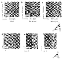
- Fe52-Co48 alloy powder (TIZ Advanced Alloy Technology Co. Ltd.) with a D50 particle size of 39 ⁇ m was used. All specimens were made on S355 steel pedestals.
- Table 4 shows the experimental condition parameters used for sample preparation of P1V1, P2V1, P3V1, P1V2, and P1V3.
- the scanning method consists of two border passes and a filling pass consisting of a reciprocating scan up to 10 mm long. For each successive slice, the scan pass was rotated 67° with respect to the stacking direction to avoid pass overlap (see FIG. 8(b)).
- Fe and Co concentrations in Fe52-Co48 alloy cubes were evaluated by Energy Dispersive X-ray Spectroscopy (EDX) (EDX, Brucker Corporation). After that, Fe52-Co48 alloy plates of 70 ⁇ 5 ⁇ 1.6 mm 3 were produced in a fully dense type and a honeycomb type. The wall thickness and cell width of the honeycomb plate were controlled to 250 ⁇ m and 2.5 mm, respectively. Electron backscatter diffraction (EBSD) was used to observe the microstructure of the Fe52-Co48 alloy. The crystal orientation and grain size of the fully densified Fe52-Co48 alloy sheets were evaluated using Atex software.
- EDX Energy Dispersive X-ray Spectroscopy
- EBSD Electron backscatter diffraction
- FIG. 9 shows a schematic diagram of the vibration/impact energy harvesting performance test.
- the vibration generator consists of an exciter (ET-132, Labworks Inc., USA), a linear power amplifier (PA-151, Labworks Inc., USA), and a function generator ( 33250A, Agilent Technologies Inc., USA). In this embodiment, sinusoidal vibration is adopted.
- the coil resistance was 11.42 k ⁇
- the load resistance was 11.72 k ⁇
- the coil diameter was 0.05 mm.
- Fig. 10 is the XRD pattern of the Fe52-Co48 alloy cube obtained using each manufacturing parameter.
- the profile of the alloy obtained using each fabrication parameter contains three strong diffraction peaks corresponding to the (110), (200) and (211) crystal planes.
- This profile consists of three strong diffraction peaks corresponding to the (110), (200), and (211) crystal planes of the body-centered cubic (bcc) phase at each process parameter.
- the lattice constant is estimated to be 0.2852 nm, which closely matches the 0.2855 nm of arc-melted FeCo.
- Fig. 11 is a secondary electron image and EDX map of the Fe52-Co48 alloy cube manufactured with P2V1 parameters. The microstructure appears uniform and free of precipitates and chemical segregation.
- FIG. 12 shows the relationship between the porosity and energy density of the Fe52-Co48 alloy cubes produced with each parameter. The porosity of the Fe52-Co48 alloy cubes produced with the P2V1 parameter was 1.5%. . The relative density of each Fe52-Co48 alloy cube exceeded 99.5% regardless of manufacturing parameters. Cube density tended to increase with volumetric energy density, except for the 300 W power case where the keyhole area was expected.
- Fig. 13 shows the appearance of the Fe52-Co48 alloy plate produced using P2V1.
- LPBF was able to produce a sheet material having both a fully dense structure and a honeycomb structure.
- Fig. 14(a) shows the relationship between the frequency of the Fe52-Co48 alloy plate and the output voltage in the vibration energy harvesting test.
- the resonance frequencies of the Fe52-Co48 alloy plates with fully dense and honeycomb structures were 487 Hz and 293 Hz, respectively. This result indicates that the structural change of the Fe52-Co48 alloy plate shifts the resonance frequency, and the honeycomb structure has a lower resonance frequency than the fully dense one. Since vibration frequencies in everyday life tend to be low, it is desirable for vibration energy harvesting devices to have low resonance frequencies.
- the honeycomb structure exhibited a power density 4.7 times higher than that of the fully dense type. It is known that the maximum output voltage of notched FeCo/Ni clad plate cantilevers is higher than that of non-notched cantilevers. This result is believed to be due to the stress concentration caused by the notch. Therefore, it is likely that the significant output power density obtained from the honeycomb structure is also due to the high stress levels. Thus, the honeycomb structure plate is considered to be effective for power generation in terms of both resonance frequency and power density.
- Fig. 15 shows the power density of the Fe52-Co48 alloy plate in the impact energy harvesting test. As shown in FIG. 15, the honeycomb structure exhibited 4.9 times the power density of the fully dense structure in the impact test. The honeycomb structure board did not break during the impact test.
- magnetostrictive materials can be used as particulate matter sensors by using shifts in resonant frequency or output voltage.
- the sensitivity of magnetostrictive particulate matter sensors is governed by their weight. Therefore, such sensors need to be lightweight in order to obtain high sensitivity.
- By using a designed structure such as a honeycomb it is possible to achieve both high energy collection performance and high sensitivity as a particulate matter sensor.
Landscapes
- Engineering & Computer Science (AREA)
- Chemical & Material Sciences (AREA)
- Materials Engineering (AREA)
- Manufacturing & Machinery (AREA)
- Mechanical Engineering (AREA)
- Physics & Mathematics (AREA)
- Optics & Photonics (AREA)
- Plasma & Fusion (AREA)
- Metallurgy (AREA)
- Organic Chemistry (AREA)
- Powder Metallurgy (AREA)
- Soft Magnetic Materials (AREA)
Priority Applications (4)
| Application Number | Priority Date | Filing Date | Title |
|---|---|---|---|
| US18/286,949 US20240196752A1 (en) | 2021-04-13 | 2022-03-11 | Method for producing magnetostrictive material, magnetostrictive material, and method for producing energy conversion member |
| CN202280028309.4A CN117157160A (zh) | 2021-04-13 | 2022-03-11 | 磁致伸缩材料的制造方法、磁致伸缩材料及能量转换构件的制造方法 |
| DE112022002100.4T DE112022002100T5 (de) | 2021-04-13 | 2022-03-11 | Herstellungsverfahren für magnetostriktives material, magnetostriktives material und herstellungsverfahren für energieumwandlungselement |
| JP2023514520A JPWO2022219981A1 (https=) | 2021-04-13 | 2022-03-11 |
Applications Claiming Priority (2)
| Application Number | Priority Date | Filing Date | Title |
|---|---|---|---|
| JP2021067990 | 2021-04-13 | ||
| JP2021-067990 | 2021-04-13 |
Publications (1)
| Publication Number | Publication Date |
|---|---|
| WO2022219981A1 true WO2022219981A1 (ja) | 2022-10-20 |
Family
ID=83640303
Family Applications (1)
| Application Number | Title | Priority Date | Filing Date |
|---|---|---|---|
| PCT/JP2022/011109 Ceased WO2022219981A1 (ja) | 2021-04-13 | 2022-03-11 | 磁歪材料の製造方法、磁歪材料およびエネルギー変換部材の製造方法 |
Country Status (5)
| Country | Link |
|---|---|
| US (1) | US20240196752A1 (https=) |
| JP (1) | JPWO2022219981A1 (https=) |
| CN (1) | CN117157160A (https=) |
| DE (1) | DE112022002100T5 (https=) |
| WO (1) | WO2022219981A1 (https=) |
Families Citing this family (1)
| Publication number | Priority date | Publication date | Assignee | Title |
|---|---|---|---|---|
| CN117884649B (zh) * | 2024-03-18 | 2024-05-14 | 兰州理工大学 | 一种磁致伸缩材料铁镓合金的激光增材制造工艺 |
Citations (4)
| Publication number | Priority date | Publication date | Assignee | Title |
|---|---|---|---|---|
| JP2018104769A (ja) * | 2016-12-27 | 2018-07-05 | 白光株式会社 | 加熱工具の先端部材の製造方法及び加熱工具の先端部材 |
| WO2018230154A1 (ja) * | 2017-06-16 | 2018-12-20 | 国立大学法人東北大学 | エネルギー変換部材、振動発電装置、力センサー装置およびアクチュエータ |
| WO2019230806A1 (ja) * | 2018-05-30 | 2019-12-05 | 株式会社 東芝 | 3dプリンタ用金属粉、造形物、および造形物の製造方法 |
| WO2020241530A1 (ja) * | 2019-05-31 | 2020-12-03 | 日立金属株式会社 | Fe-Al系合金制振部品およびその製造方法 |
Family Cites Families (5)
| Publication number | Priority date | Publication date | Assignee | Title |
|---|---|---|---|---|
| JP6073772B2 (ja) | 2013-10-25 | 2017-02-01 | ヤンマー株式会社 | エンジン |
| JP2015141964A (ja) | 2014-01-28 | 2015-08-03 | 英樹 原田 | 磁気異方性積層成形方法及び該方法により製造された磁気異方性磁石及びそれに用いる顆粒の製造方法 |
| US10056541B2 (en) * | 2014-04-30 | 2018-08-21 | Apple Inc. | Metallic glass meshes, actuators, sensors, and methods for constructing the same |
| CN106825542B (zh) * | 2017-01-19 | 2019-03-22 | 吉林大学 | 负泊松比高磁致伸缩材料及其增材制造方法 |
| JP2019198886A (ja) * | 2018-05-18 | 2019-11-21 | 富士通アイソテック株式会社 | 金属溶融3dプリンタの造形データ作成方法および造形データ作成プログラム、並びに、金属溶融3dプリンタ |
-
2022
- 2022-03-11 DE DE112022002100.4T patent/DE112022002100T5/de active Pending
- 2022-03-11 CN CN202280028309.4A patent/CN117157160A/zh active Pending
- 2022-03-11 WO PCT/JP2022/011109 patent/WO2022219981A1/ja not_active Ceased
- 2022-03-11 US US18/286,949 patent/US20240196752A1/en active Pending
- 2022-03-11 JP JP2023514520A patent/JPWO2022219981A1/ja active Pending
Patent Citations (4)
| Publication number | Priority date | Publication date | Assignee | Title |
|---|---|---|---|---|
| JP2018104769A (ja) * | 2016-12-27 | 2018-07-05 | 白光株式会社 | 加熱工具の先端部材の製造方法及び加熱工具の先端部材 |
| WO2018230154A1 (ja) * | 2017-06-16 | 2018-12-20 | 国立大学法人東北大学 | エネルギー変換部材、振動発電装置、力センサー装置およびアクチュエータ |
| WO2019230806A1 (ja) * | 2018-05-30 | 2019-12-05 | 株式会社 東芝 | 3dプリンタ用金属粉、造形物、および造形物の製造方法 |
| WO2020241530A1 (ja) * | 2019-05-31 | 2020-12-03 | 日立金属株式会社 | Fe-Al系合金制振部品およびその製造方法 |
Also Published As
| Publication number | Publication date |
|---|---|
| CN117157160A (zh) | 2023-12-01 |
| JPWO2022219981A1 (https=) | 2022-10-20 |
| DE112022002100T5 (de) | 2024-02-29 |
| US20240196752A1 (en) | 2024-06-13 |
Similar Documents
| Publication | Publication Date | Title |
|---|---|---|
| Kurita et al. | Additive manufacturing and energy-harvesting performance of honeycomb-structured magnetostrictive Fe52–Co48 alloys | |
| US20100006183A1 (en) | Method for producing a giant magnetostrictive alloy | |
| Thorsson et al. | Selective laser melting of a Fe-Si-Cr-BC-based complex-shaped amorphous soft-magnetic electric motor rotor with record dimensions | |
| Gao et al. | Laser-beam powder bed fusion followed by annealing with stress: A promising route for magnetostrictive improvement of polycrystalline Fe81Ga19 alloys | |
| Adnan Islam et al. | Progress in dual (piezoelectric‐magnetostrictive) phase magnetoelectric sintered composites | |
| CN116114038B (zh) | 用于定制磁性的方法及由此获得的结构 | |
| EP1124268A2 (en) | Giant magnetostrictive material and manufacturing method thereof, and magnetostrictive actuator and magnetostrictive sensor therewith | |
| Song et al. | Enhancement of magnetoelectric (ME) coupling by using textured magnetostrictive alloy in 2-2 type ME laminate | |
| WO2022219981A1 (ja) | 磁歪材料の製造方法、磁歪材料およびエネルギー変換部材の製造方法 | |
| US20050161119A1 (en) | Directionally oriented particle composites | |
| Jen et al. | Structural, magneto-mechanical, and damping properties of slowly-cooled polycrystalline Fe81Ga19 alloy | |
| Deng et al. | Enhancement magnetoelectric effect in Metglas-Fe by annealing | |
| Zhou et al. | Magnetoelectric energy harvester | |
| Nersessian et al. | Hollow and solid spherical magnetostrictive particulate composites | |
| Wei et al. | Electrochemical production of a magnetic Ni3Si template in lamellar Ni–Si eutectic alloy | |
| Meloy et al. | Magnetic property-texture relationships in galfenol rolled sheet stacks | |
| Faidley et al. | Modulus increase with magnetic field in ferromagnetic shape memory Ni–Mn–Ga | |
| WO2023176869A1 (ja) | 磁歪材料、エネルギー変換部材およびその製造方法ならびに振動発電装置 | |
| Murray | Magneto-mechanical properties and applications of Ni-Mn-Ga ferromagnetic shape memory alloy | |
| Muchenik et al. | Prediction of extrinsic charge, voltage, and work-conversion factors for laminated magnetoelectric composites | |
| Downey | Characterization of bending magnetostriction in iron-gallium alloys for nanowire sensor applications | |
| Feliciano | Development and characterisation of soft magnetic iron-silicon alloys for laser beam powder bed fusion additive manufacturing | |
| Taheri | Design, processing and characterization of mechanically alloyed Galfenol & lightly rare-earth doped FeGa alloys as smart materials for actuators and transducers | |
| Okazaki et al. | Developments of new thermo-and magneto-elastic metallic sensor/actuator materials by controlling microstructures by rapid-solidification | |
| Pramanick et al. | Characterization of magnetoelastic coupling in ferromagnetic shape memory alloys using neutron diffraction |
Legal Events
| Date | Code | Title | Description |
|---|---|---|---|
| 121 | Ep: the epo has been informed by wipo that ep was designated in this application |
Ref document number: 22787907 Country of ref document: EP Kind code of ref document: A1 |
|
| WWE | Wipo information: entry into national phase |
Ref document number: 18286949 Country of ref document: US Ref document number: 2023514520 Country of ref document: JP |
|
| WWE | Wipo information: entry into national phase |
Ref document number: 112022002100 Country of ref document: DE |
|
| 122 | Ep: pct application non-entry in european phase |
Ref document number: 22787907 Country of ref document: EP Kind code of ref document: A1 |