WO2022219920A1 - 電子制御装置及び電子制御システム - Google Patents
電子制御装置及び電子制御システム Download PDFInfo
- Publication number
- WO2022219920A1 WO2022219920A1 PCT/JP2022/006524 JP2022006524W WO2022219920A1 WO 2022219920 A1 WO2022219920 A1 WO 2022219920A1 JP 2022006524 W JP2022006524 W JP 2022006524W WO 2022219920 A1 WO2022219920 A1 WO 2022219920A1
- Authority
- WO
- WIPO (PCT)
- Prior art keywords
- power supply
- data
- terminal
- power
- electronic control
- Prior art date
- Legal status (The legal status is an assumption and is not a legal conclusion. Google has not performed a legal analysis and makes no representation as to the accuracy of the status listed.)
- Ceased
Links
Images




Classifications
-
- B—PERFORMING OPERATIONS; TRANSPORTING
- B60—VEHICLES IN GENERAL
- B60R—VEHICLES, VEHICLE FITTINGS, OR VEHICLE PARTS, NOT OTHERWISE PROVIDED FOR
- B60R16/00—Electric or fluid circuits specially adapted for vehicles and not otherwise provided for; Arrangement of elements of electric or fluid circuits specially adapted for vehicles and not otherwise provided for
- B60R16/02—Electric or fluid circuits specially adapted for vehicles and not otherwise provided for; Arrangement of elements of electric or fluid circuits specially adapted for vehicles and not otherwise provided for electric constitutive elements
- B60R16/023—Electric or fluid circuits specially adapted for vehicles and not otherwise provided for; Arrangement of elements of electric or fluid circuits specially adapted for vehicles and not otherwise provided for electric constitutive elements for transmission of signals between vehicle parts or subsystems
- B60R16/0231—Circuits relating to the driving or the functioning of the vehicle
-
- B—PERFORMING OPERATIONS; TRANSPORTING
- B60—VEHICLES IN GENERAL
- B60R—VEHICLES, VEHICLE FITTINGS, OR VEHICLE PARTS, NOT OTHERWISE PROVIDED FOR
- B60R16/00—Electric or fluid circuits specially adapted for vehicles and not otherwise provided for; Arrangement of elements of electric or fluid circuits specially adapted for vehicles and not otherwise provided for
- B60R16/02—Electric or fluid circuits specially adapted for vehicles and not otherwise provided for; Arrangement of elements of electric or fluid circuits specially adapted for vehicles and not otherwise provided for electric constitutive elements
- B60R16/023—Electric or fluid circuits specially adapted for vehicles and not otherwise provided for; Arrangement of elements of electric or fluid circuits specially adapted for vehicles and not otherwise provided for electric constitutive elements for transmission of signals between vehicle parts or subsystems
-
- G—PHYSICS
- G06—COMPUTING OR CALCULATING; COUNTING
- G06F—ELECTRIC DIGITAL DATA PROCESSING
- G06F1/00—Details not covered by groups G06F3/00 - G06F13/00 and G06F21/00
- G06F1/26—Power supply means, e.g. regulation thereof
-
- G—PHYSICS
- G06—COMPUTING OR CALCULATING; COUNTING
- G06F—ELECTRIC DIGITAL DATA PROCESSING
- G06F1/00—Details not covered by groups G06F3/00 - G06F13/00 and G06F21/00
- G06F1/26—Power supply means, e.g. regulation thereof
- G06F1/263—Arrangements for using multiple switchable power supplies, e.g. battery and AC
-
- H—ELECTRICITY
- H02—GENERATION; CONVERSION OR DISTRIBUTION OF ELECTRIC POWER
- H02J—ELECTRIC POWER NETWORKS; CIRCUIT ARRANGEMENTS OR SYSTEMS FOR SUPPLYING OR DISTRIBUTING ELECTRIC POWER; SYSTEMS FOR STORING ELECTRIC ENERGY
- H02J1/00—Circuit arrangements for DC mains or DC distribution networks
-
- H—ELECTRICITY
- H02—GENERATION; CONVERSION OR DISTRIBUTION OF ELECTRIC POWER
- H02J—ELECTRIC POWER NETWORKS; CIRCUIT ARRANGEMENTS OR SYSTEMS FOR SUPPLYING OR DISTRIBUTING ELECTRIC POWER; SYSTEMS FOR STORING ELECTRIC ENERGY
- H02J3/00—Circuit arrangements for AC mains or AC distribution networks
- H02J3/38—Arrangements for feeding a single network from two or more generators or sources in parallel; Arrangements for feeding already energised networks from additional generators or sources in parallel
Definitions
- the present invention relates to an electronic control device and an electronic control system, and more specifically to an electronic control device and an electronic control system that utilize power superimposition.
- Level 3 is conditional automated driving, where the system normally controls driving and monitors the surroundings, and the driver drives only in emergencies.
- the driver does not always hold the steering wheel, so it may not be possible to immediately transfer control of the vehicle to the driver. Therefore, it is necessary for the system to drive safely during the time it takes for the system to detect a failure and transfer control of the vehicle to the driver. In other words, it is necessary to build a redundant system that does not stop the system completely even in the event of a failure, but moves to a degenerate system with limited functions.
- FIG. 13 shows a schematic diagram of a single system configuration of level 2 or lower, taking a brake as an example.
- An actuator (brake) 800 performs braking according to a signal from an electronic control unit (ECU) 801 .
- ECU electronice control unit
- the ECU 801 is driven by electric power supplied through a power line 803 from a power supply 802 mounted on the vehicle. Then, the ECU 801 monitors the surroundings based on information from a sensor 804 (front-monitoring radar, etc.) and, when judging danger, transmits a stop signal to the actuator (brake) 800 via the data line 805 . Even if a part of this system fails and cannot operate normally, the driver is responsible for driving control, and the driver steps on the brake to stop the vehicle, so there is no problem as a system. Note that "Driver+" in FIG. 13 indicates that the driver is responsible for braking in addition to the above automatic system.
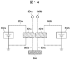
- Fig. 14 shows a schematic diagram of a duplex system configuration of level 3 or higher, taking brakes as an example.
- a single-system system (FIG. 13) is parallelized including power sources 802a and 802b and power lines 803a and 803b to form a dual system. With this configuration, even if one system fails, the other system can be used to stop the vehicle. However, since the power supply and power lines affect the entire system, there is a strong demand for redundancy of two independent systems.
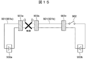
- FIG. 15 shows an in-vehicle backbone network configuration in a daisy chain described in Patent Document 1. As shown in FIG. FIG. 15 is created based on FIG. 90 of Patent Document 1. FIG.
- Patent Document 1 paragraphs [0431] to [0436]
- two independent power sources 900a and 900b are installed in the vehicle and connected by a power line 901 via a power source changeover switch 902.
- Electronic control units (ECUs) 903a, 903b, and 903c are connected to this power line 901 as a daisy chain backbone network. Data is superimposed on the power line 901 to communicate between the ECUs 903a, 903b, and 903c. Normally, power is supplied only from power source 900 a via power line 901 .
- the power supply switch 902 is turned on and power is also supplied from the power supply 900b.
- Patent Document 1 as described above (FIG. 15 of the present application) is configured to superimpose a signal on the power line 901, and this power line 901 is not designed for impedance, and is capable of performing 10 Gbps-class data communication. is tough. Therefore, it is difficult to apply to a system of level 3 or higher because camera data cannot be transmitted.
- the power supply redundancy required for systems of Level 3 or higher it is preferable to install at least three networks, the main power supply network, the redundant power supply network, and the data wiring network, with wired cables throughout the vehicle.
- the number of wires increases, leading to an increase in wire harness weight.
- the present invention has been made in consideration of the above problems, and aims to provide an electronic control device and an electronic control system that can provide redundant power supply while suppressing an increase in the number of wires.
- an electronic control device includes: An electronic controller having a data processing circuit for data communication with one or more other electronic controllers, a power terminal connected to the first power supply; a first data terminal connected to a first external data line for performing data communication with the other electronic control device and receiving power supply from the other electronic control device; a first internal data line connecting between the first data terminal and the data processing circuit to transmit a data signal from the first data terminal to the data processing circuit;
- the power supply terminal and the first data terminal are connected to the input side, the data processing circuit is connected to the output side, and one of the power supply terminal and the first data terminal on the input side is supplied to the data processing circuit.
- a power supply selection circuit that selects the power with a higher potential and connects it to the data processing circuit on the output side; characterized by having
- the present invention by enabling the first external data line to be used as the second external power line separately from the first external power line, power can be supplied to the data processing circuit while suppressing the number of external power lines. redundancy can be ensured. Further features related to the present invention will become apparent from the description of the specification and the accompanying drawings. Further, problems, configurations, and effects other than those described above will be clarified by the following description of the embodiments.
- FIG. 5 is a diagram showing the configuration of a filter circuit, etc., and its periphery according to the second embodiment
- FIG. 7 is a diagram showing an example of signals used in the electronic control system according to the second embodiment
- FIG. 10 is a diagram showing an example of power supply redundancy in the conventional technology
- FIG. 1 is a diagram showing the configuration of an electronic control unit according to a first embodiment of the invention.
- An electronic control unit (hereinafter also referred to as "ECU 1") 1 is mounted on a vehicle, for example, and performs various types of control related to the vehicle.
- the ECU 1 performs data communication with a plurality of other electronic control units via the first external data line 50a and the second external data line 50b.
- the first external data line 50a and the second external data line 50b are impedance-designed and enable power transmission and power reception in addition to data communication.
- the first external data line 50a and the second external data line 50b can be either the same or different.
- the ECU 1 is connected to the first power supply 60 and can be supplied with power from the first power supply 60 .
- the ECU 1 has a first data terminal 101a connected to the first external data line 50a, and receives power supply from another electronic control device by superimposing power on the first external data line 50a. This makes it possible to achieve power supply redundancy.
- the ECU 1 includes a power supply terminal 105 connected to a first power supply 60, and a first external data line 50a for performing data communication with another electronic control device and for receiving power supply from the other electronic control device.
- a power source selection circuit 131 that selects the power with the higher potential to be supplied and connects it to the data processing circuit 100 on the output side.
- the ECU 1 has a power terminal 105 connected to the first power supply 60 via the first power supply line 52 .
- the power terminal 105 is connected to the data processing circuit 100 via the first internal power line 110 .
- a power supply path configured by the power supply terminal 105 and the first internal power line 110 is hereinafter referred to as a first power supply path 117 .
- the first internal power line 110 is provided with a power source selection circuit 131 and is connected to the second internal power line 120 .
- the second internal power line 120 connects the power selection circuit 131 of the first internal power line 110 and the filter circuit 104a.
- the second internal power line 120 passes current from the first data terminal 101a to the first internal power line 110 side.
- the first internal data line 102a is provided with a filter circuit 104a for separating data and power.
- the filter circuit 104a separates power from data input from the first external data line 50a to the first data terminal 101a, supplies the data to the data processing circuit 100, and supplies power from the second internal power line 120 to the power supply selection circuit. 131.
- the first data terminal 101a, a portion of the first internal data line 102a (the portion from the first data terminal 101a to the filter circuit 104a), the second internal power line 120, and a portion of the first internal power line 110 (power source selection A power supply path formed by the portion from the circuit 131 to the data processing circuit 100) is referred to as a second power supply path 124 .
- the power supply selection circuit 131 connects between the power supply terminal 105 and the first internal power line 110 to switch the power of the first power supply 60 to the first power supply. It is supplied to data processing circuit 100 by supply path 117 .
- the power supply route is switched by the power supply selection circuit 131 to switch between the second internal power line 120 and the second internal power line 120.
- the power supplied to the first data terminal 101a through the first external data line 50a is supplied to the data processing circuit 100 through the second power supply path 124.
- the ECU 1 in this embodiment has a second data terminal 101b connected to the second external data line 50b, and by superimposing the power supply on the second external data line 50b, it is possible to further control other electronic control units. to allow power to be supplied to
- the ECU 1 is connected to a second external data line 50b for performing data communication with another electronic control device different from the other electronic control device and for supplying power to the other different electronic control device. and a second data terminal 101b.
- the output side of the power selection circuit 131 is connected not only to the data processing circuit 100 but also to the second data terminal 101b.
- the second data terminal 101b and the data processing circuit 100 are connected by a second internal data line 102b, and the electronic control unit 1 receives data from the second data terminal 101b through the second external data line 50b. Data can be bi-directionally communicated with the electronic control unit.
- a filter circuit 104b for synthesizing data and power is provided in the middle of the second internal data line 102b.
- a third internal power line 140 connects between the filter circuit 104b and the power supply selection circuit 131, and power from the power supply selected by the power supply selection circuit 131 is supplied to the filter circuit 104b through the third internal power line 140. be.
- the power supplied from the third internal power line 140 and the data supplied from the data processing circuit 100 are synthesized, and the power supplied from the second data terminal 101b through the second external data line 50b is transmitted to a different other power line. Output to the electronic control unit.
- a power supply path formed by the power source selection circuit 131, the third internal power line 140, and a portion of the second internal data line 102b (the portion from the filter circuit 104b to the second data terminal 101b) will be referred to as a third power supply path. 142.
- the power supply to the data processing circuit 100 consists of the first power supply path 117 from the first power supply 60 to the data processing circuit 100 and the second power supply path 117 from another electronic control device to the data processing circuit 100 .
- 2 power supply path 124 is switched.
- the power supply selection circuit 131 compares the power input from the power supply terminal 105 with the other power input from the first data terminal 101a, selects one of them, and outputs it as the power supply for the data processing circuit 100 and the like. .
- the power selected by the power source selection circuit 131 is the power that is input from the first power source 60 to the power source selection circuit 131 via the power source terminal 105, or the power that is input from the first external data line 50a to the first data terminal 101a and the filter circuit 104a. , the power input to the power source selection circuit 131 via the second internal power line 120 . If a problem occurs on the output power supply side due to a failure of one of the power supplies during operation, the other power supply is switched to enable continuous operation, realizing power supply redundancy. .
- FIG. 2 is a diagram schematically showing a vehicle 10 equipped with an electronic control system 11 (or an in-vehicle network) according to a second embodiment of the invention.
- the electronic control system 11 has an integrated electronic control device 20 , an area electronic control device 30 and a terminal electronic control device 40 .
- the terminal electronic control unit 40 (hereinafter also referred to as “terminal ECU 40” or “ECU 40”) individually controls various sensors, actuators, etc., and is arranged in various places of the vehicle 10.
- the terminal ECU 40 performs various types of control such as surrounding monitoring, information acquisition and control of the engine.
- the integrated electronic control unit 20 (hereinafter also referred to as “integrated ECU 20" or “ECU 20") grasps the overall vehicle 10 and surrounding conditions based on various information from each terminal ECU 40, and continues safe driving. , and transmits control information to each terminal ECU 40 .
- an area electronic control unit 30 (hereinafter also referred to as "area ECU 30" or "ECU 30") is provided between the terminal ECU 40 and the integrated ECU 20 as a repeater for collecting and diffusing data. It is also possible to configure such that all the data from the terminal ECU 40 is sent to the integrated ECU 20, but in that case the integrated ECU 20 would need a huge processing capacity, and problems such as heat radiation measures and an increase in cost would arise. Therefore, although not shown, each ECU 30, 40 can perform processing by using a central processing unit (CPU) provided in each ECU 30, 40 depending on the function.
- CPU central processing unit
- the integrated ECU 20 and each area ECU 30 perform data communication via the first external data line 50a.
- Each area ECU 30 and each terminal ECU 40 perform data communication via the second external data line 50b.
- the electronic control system 11 has a plurality of power supplies, that is, a first power supply 60 and a second power supply 61 for redundancy.
- the first power source 60 and the second power source 61 can be implemented by secondary batteries or generators, for example.
- the generator also includes an alternator.
- the integrated ECU 20 is powered by a first power supply 60 and a second power supply 61 respectively.
- the area ECU 30 is powered only from the first power supply 60 .
- power can be supplied from the integrated ECU 20 to the area ECU 30 by superimposing power on the first external data line 50a.
- the area ECUs 30 to which power is supplied using power supply superimposition may be limited to only some area ECUs 30 . In that case, the area ECU 30 that does not use power supply superimposition may be powered by one or both of the first power supply 60 and the second power supply 61 .
- the terminal ECU 40 is powered by the first power supply 60 or the second power supply 61 .
- FIG. 3 is a diagram showing the configuration of part of the electronic control system 11 according to the second embodiment.
- two ECUs ie, an integrated ECU 20 and an area ECU 30 are shown.
- the integrated ECU 20 and the area ECU 30 perform bidirectional data communication with each other.
- the integrated ECU 20 and the area ECU 30 correspond to the second electronic control unit and the first electronic control unit of claim 5 of the scope of claims.
- the terminal ECU 40 is not shown in FIG. 3 because it is individually supplied with power from the first power supply 60 or the second power supply 61 .
- power is supplied to the integrated ECU 20 from a first power supply 60 and a second power supply 61 .
- Electric power is supplied from the first power source 60 to the area ECU 30 .
- the area ECU 30 is supplied with power from the first power supply 60 or the second power supply 61 supplied to the integrated ECU 20 via the first external data line 50a (power supply superimposition).
- the integrated ECU 20 and the area ECU 30 have data processing circuits 200 and 300 that perform data processing according to their respective functions.
- the data processing circuits 200 and 300 process signals from switches, LSI, SoC (System on Chip), etc. in the electronic control system 11 .
- the data processing circuits 200 and 300 of the integrated ECU 20 and the area ECU 30 communicate with each other via the first external data line 50a.
- the integrated ECU 20 includes a plurality of first data input/output terminals 201a (hereinafter also referred to as "first data terminals 201a") to which the first external data lines 50a are connected, the first data terminals 201a and a data processing circuit (first data terminal 201a). 2 data processing circuit) 200 are provided.
- a filter circuit 204a is provided on the first internal data line 202a. Details of the filter circuit 204a will be described later with reference to FIG.
- the data processing circuit 200 of the integrated ECU 20 exchanges signals with the data processing circuit (first data processing circuit) 300 of the area ECU 30 via the first internal data line 202a, the first data terminal 201a and the first external data line 50a. Send and receive.
- the integrated ECU 20 also has power supply terminals 205 a and 205 b as input/output interfaces with the first power supply 60 and the second power supply 61 .
- a first power line 51a connected to the first power supply 60 is connected to the power terminal 205a, and a second power line 51b connected to the second power supply 61 is connected to the power terminal 205b.
- Power supply terminals 205 a and 205 b are connected to data processing circuit 200 via first internal power line 210 .
- the first internal power line 210 has a branch portion 211 connected to the power terminal 205a, a branch portion 212 connected to the power terminal 205b, and a junction portion 213 where the branch portions 211 and 212 join.
- the branches 211 and 212 are provided with rectifying circuits having first rectifying elements 214 and 215 such as diodes.
- the rectifier circuit supplies power from the first power supply 60 to the data processing circuit 200 when the potential of the first power supply 60 is higher than that of the second power supply 61 , and the first power supply 60 is higher than the second power supply 61 .
- the potential is low, power is supplied from the second power supply 61 to the data processing circuit 200 and the first data terminal 201a.
- a step-down DC/DC converter 216 is provided at the junction 213 of the first internal power line 210 .
- the DC/DC converter 216 steps down the power supply voltage of the first power supply 60 or the second power supply 61 and supplies it to the data processing circuit 200 .
- the voltage of the power supply signal superimposed on the first external data line 50a is set to a voltage higher than the driving voltage of the data processing circuit 200, such as 12 V, 24 V, 36 V, or 48 V, thereby reducing power transmission loss. Suppress growth.
- the DC/DC converter 216 may be of a buck-boost type or a boost type.
- a power supply path configured by the power supply terminals 205 a and 205 b and the first internal power line 210 is hereinafter referred to as a first power supply path 217 .
- a second internal power line 220 is connected to the first internal power line 210 .
- Second internal power line 220 connects connection portion 221 with first internal power line 210 and filter circuit 204a.
- the power from the first power supply 60 or the second power supply 61 via the power supply terminals 205a and 205b can be supplied to the filter circuit 204a as well.
- FIG. 4 is a diagram showing a configuration of a filter circuit 204a (and a filter circuit 304a to be described later) and its periphery according to the second embodiment.
- the filter circuit 204a combines or separates the data signal and the power supply signal. Since the data signal and the power supply signal have different frequency components, they can be separated or combined using filters with different frequency characteristics.
- Filter circuit 204 a has a high pass filter 208 arranged on first internal data line 202 a and a low pass filter 209 arranged on second internal power line 220 .
- the high-pass filter 208 is implemented by capacitors or the like arranged in series. Therefore, the high-pass filter 208 does not pass low-frequency band signals such as power supply signals, and only passes high-frequency band data signals. Therefore, the high-pass filter 208 passes a data signal from the data processing circuit 200 of the integrated ECU 20 to the data processing circuit 300 of the area ECU 30 and a data signal from the data processing circuit 300 of the area ECU 30 to the data processing circuit 200 of the integrated ECU 20. . However, the high-pass filter 208 does not pass the power signal from the first power supply 60 or the second power supply 61 supplied via the second internal power line 220 to the data processing circuit 200 side or the first data terminal 201a side.
- the low-pass filter 209 is implemented by arranging coils or ferrite beads in series. Therefore, the low-pass filter 209 passes low-frequency band signals such as power supply signals, and does not pass high-frequency band data signals. Therefore, the low-pass filter 209 passes the power signal from the first power supply 60 or the second power supply 61 supplied through the second internal power line 220 to the first data terminal 201a side. However, the low-pass filter 209 filters the data signal from the data processing circuit 200 of the integrated ECU 20 to the data processing circuit 300 of the area ECU 30 and the data signal from the data processing circuit 300 of the area ECU 30 to the data processing circuit 200 of the integrated ECU 20. 2 Do not pass through the internal power line 220 side.
- a power supply path formed by the second internal power line 220, a portion of the first internal data line 202a (the portion from the filter circuit 204a to the first data terminal 201a), and the first data terminal 201a will be referred to as the second power line.
- supply path 224 Referred to as supply path 224 (FIG. 3).
- FIG. 5 is a diagram showing an example of signals used in the electronic control system 11 according to the second embodiment.
- voltage Vd is the voltage of the data signal output from data processing circuit 200 of integrated ECU 20 (that is, the voltage on first internal data line 202a between data processing circuit 200 and high-pass filter 208).
- the voltage Vs is the power supply voltage of the first power supply 60 or the second power supply 61 supplied via the second internal power line 220 of the integrated ECU 20 .
- a voltage Vtotal represents a voltage obtained by superimposing the voltage Vd and the voltage Vs (that is, the voltage on the first external data line 50a).
- FIG. 5(B) is a diagram extracting only the power supply voltage Vs of FIG. 5(A). The average voltage difference between the power supply (+) and the power supply (-) becomes the driving voltage of the electronic control unit 1.
- FIG. 5A is the voltage of the data signal output from data processing circuit 200 of integrated ECU 20 (that is, the voltage on first internal data line 202a between data processing circuit 200 and
- the power supply signal is superimposed on the data signal to perform communication and power transmission/reception through the first external data line 50a.
- the area ECU 30 is provided with a plurality of first data terminals 301 a to which the first external data lines 50 a are connected, and a plurality of first internal data lines 302 a connecting the first data terminals 301 a and the data processing circuit 300 .
- a filter circuit 304a is provided on the first internal data line 302a.
- the data processing circuit 300 of the area ECU 30 transmits and receives signals to and from the data processing circuit 200 of the integrated ECU 20 via the first internal data line 302a, the filter circuit 304a, the first data terminal 301a and the first external data line 50a. .
- the signal supplied from the integrated ECU 20 to the area ECU 30 via the first external data line 50a includes the data signal from the data processing circuit 200 and the power signal from the first power supply 60 or the second power supply 61. are superimposed.
- a data signal of this superimposed signal is extracted by the high-pass filter 308 (FIG. 4) of the filter circuit 304 a of the area ECU 30 and supplied to the data processing circuit 300 .
- the area ECU 30 also has a power supply terminal 305 as an input/output interface with the first power supply 60 .
- a power supply line 52 connected to the first power supply 60 is connected to the power supply terminal 305 .
- the integrated ECU 20 has two power supply terminals 205 a and 205 b , but the area ECU 30 has one power supply terminal 305 .
- the power terminal 305 is connected to the data processing circuit 300 via the first internal power line 310 .
- the first internal power line 310 is provided with a first rectifying element 314 such as a diode and a step-down DC/DC converter 316 .
- the first rectifying element 314 prevents backflow to the first power supply 60 side.
- the DC/DC converter 316 steps down the power supply voltage of the first power supply 60 and supplies it to the data processing circuit 300 .
- the DC/DC converter 316 may be of a step-up/step-down type or step-up type.
- a power supply path configured by the power supply terminal 305 and the first internal power line 310 is hereinafter referred to as a first power supply path 317 .
- a second internal power line 320 is connected to the first internal power line 310 .
- the second internal power line 320 connects the connection portion 321 with the first internal power line 310 and the filter circuit 304a.
- the second internal power line 220 of the integrated ECU 20 passes the current from the first power supply 60 and the second power supply 61 side to the first data terminal 201a. In other words, the second internal power line 220 of the integrated ECU 20 was for supplying power from the integrated ECU 20 to the area ECU 30 .
- the second internal power line 320 of the area ECU 30 in the second embodiment passes current from the first data terminal 301a to the first internal power line 310 side. That is, as described above, the signal supplied from the integrated ECU 20 to the area ECU 30 via the first external data line 50a includes the data signal from the data processing circuit 200 and the power supply from the first power supply 60 or the second power supply 61. Signals are superimposed (see FIG. 5A). A power supply signal (power supply voltage) is extracted from this superimposed signal by the low-pass filter 309 (FIG. 4) of the filter circuit 304a of the area ECU 30 and supplied to the second internal power line 320 (see FIG. 5B).
- the data processing circuit 300 of the area ECU 30 is supplied from the integrated ECU 20 via the first external data line 50a. Electricity can be supplied.
- the first data terminal 301a, a portion of the first internal data line 302a (the portion from the first data terminal 301a to the filter circuit 304a), the second internal power line 320, and a portion of the first internal power line 310 (connecting portion 321 to the data processing circuit 300 ) is called a second power supply path 324 .
- second rectifying elements 330a and 330b are provided for passing the current from the filter circuit 304a to the connecting portion 321. As a result, it is possible to prevent backflow from the first internal power line 310 to the filter circuit 304a side.
- the first rectifying element 314 on the first internal power line 310 and the second rectifying elements 330 a and 330 b on the second internal power line 320 constitute a power supply selection circuit 331 .
- the first rectifying element 314 and the second rectifying elements 330a and 330b may be of the same standard, but may be of different standards.
- the power selection circuit 331 selects either the first power supply path 317 or the second power supply path 324 to supply power to the data processing circuit 300 . In the second embodiment, the power selection circuit 331 selects the first power supply path 317 or the second power supply path 327 whichever has the higher voltage (potential) to be supplied to the data processing circuit 300 .
- the power selection circuit 331 has an input side connected to the power terminal 305 and the first data terminal 301a, and an output side connected to the data processing circuit 300. It has a function of selecting the one with the higher electric potential and connecting it to the data processing circuit 300 on the output side.
- FIG. 6 is a diagram showing the configuration of the power supply selection circuit 331 of the area ECU 30 according to the second embodiment.
- the power P1 from the first power supply 60 is configured to be supplied to the data processing circuit 300 via the first power supply path 317 .
- the power supply voltages of the first power supply 60 and the second power supply 61 are designed to be the same under normal conditions.
- the voltage drop in the second power supply path 324 caused by the second rectifying elements 330 a and 330 b is set to be greater than the voltage drop in the first power supply path 317 caused by the first rectifying element 314 . Therefore, in a normal state, the output voltage of the first rectifying element 314 (or the voltage V1 before the first rectifying element 314) is the output voltage of the second rectifying element 330b closest to the connecting portion 321 (or the second rectifying element 330b (V1>V2), the output voltage Vo on the side of the connecting portion 321 becomes equal to the output voltage of the first rectifying element 314. Thereby, the power P1 from the first power supply 60 is supplied to the data processing circuit 300 via the first power supply path 317 .
- the output voltage of the first rectifying element 314 (or the voltage V1 before the first rectifying element 314) changes to the output voltage of the second rectifying element 330b closest to the connecting portion 321 (or When it becomes lower than the voltage V2 before the second rectifying element 330b (V1 ⁇ V2), the output voltage Vo on the side of the connecting part 321 becomes equal to the output voltage of the second rectifying element 330b.
- the power P2 from the integrated ECU 20 is supplied to the data processing circuit 300 via the second power supply path 324 . Therefore, redundant power supply to the data processing circuit 300 can be achieved.
- a portion of the first internal power line 310 that causes a voltage drop by the first rectifying element 314 is called a first voltage drop portion
- a portion of the second internal power line 320 that causes a voltage drop by the second rectifying elements 330a and 330b is called a second voltage drop portion. It is called a voltage drop section.
- the first voltage drop section has one first rectifying element 314 .
- the first voltage drop section may have other configurations (eg, two first rectifying elements 314).
- the second voltage drop section has a plurality of (two) second rectifying elements 330a and 330b.
- the first rectifying element 314 and the second rectifying elements 330a and 330b are arranged in parallel with the input side as the anode and the output side as the cathode, and the cathode side is integrated into one connecting portion 321.
- Each of the rectifying elements 314, 330a, 330b compares the voltages of the anode and the cathode. When the anode voltage is high, the rectifying elements 314, 330a, 330b are conductive, and when the anode voltage is low, they are insulated.
- the voltage V1 and the voltage V2 are compared, and if the voltage V1 is higher, the first rectifying element 314 becomes conductive and the power P1 from the first power supply 60 becomes the output of the power supply selection circuit 331 . Conversely, if the voltage V1 is lower than the voltage V2, the second rectifying elements 330a and 330b become conductive, and the power P2 from the first external data line 50a becomes the output of the power supply selection circuit 331.
- the cable for power supply wiring is thicker than the core wire of the data line, so the wiring resistance is small and the power transmission efficiency is high. Therefore, in normal times, if the power supply (here, the first power supply 60) is configured to preferentially select the power supply, the loss in the power supply path can be reduced, so the voltage V1>V2. is desirable. Therefore, there are more first rectifying elements 314 in the power supply path (second power supply path 324) from the first external data line 50a than in the power supply path (first power supply path 317) from the first power supply 60. are inserted in series. As a result, the second rectifying elements 330a and 330b normally ensure the relationship of V1>V2 due to the voltage drop occurring at the PN junction.
- the output of the power supply selection circuit 331 is seamlessly switched to the power P2 from the first external data line 50a without an external signal. Switching and continuous operation are possible.
- a high-frequency cable basically consists of two wires physically, and power supply signals of power (+) and power (-) are superimposed on each of these two wires.
- two-way data communication is performed using a pair of pair cables such as UTP (Unshielded Twist Pair), STP (Shielded Twist Pair), and SPP (Shielded Parallel Pair).
- UTP Unshielded Twist Pair
- STP shieldded Twist Pair
- SPP shieldded Parallel Pair
- power signals that can be superimposed on a pair of paired cables are unidirectional. Therefore, in the second embodiment, power is supplied from the integrated ECU 20 having a power transmission function to the area ECU 30 having a power reception function.
- the first external data line 50a is shown as two lines for simplification, but it may be composed of three or more lines. Then, it is possible to configure such that the power supply signal is superimposed on one or more of the wirings.
- the first data terminals 301 and the first internal data lines 302a are also provided in numbers corresponding to the number of wirings.
- the external data lines 50a and 50b are cables designed for data communication impedance, there is a limit to the thickness of the core line. As a result, wiring resistance increases, and there is concern about an increase in transmission loss of power supply signals. In general, when transmitting the same power signal, increasing the voltage and decreasing the current reduces the transmission loss.
- the data processing circuits 200 and 300 are mainly made of semiconductors driven at a power supply voltage of 5 V or less as the speed of communication increases. Therefore, a DC/DC converter 316 is provided between the output of the power supply selection circuit 331 and the data processing circuit 300 .
- the voltage of the power supply superimposed on the first data line 50a is set to a voltage higher than the power supply voltage of the data processing circuit 300, such as 12 V, 24 V, 36 V, or 48 V, thereby suppressing an increase in transmission loss. oppress.
- the power selection circuit 331 selects the first power supply path 317 or the second power supply path 324, whichever has the higher supply voltage to the data processing circuit 300 (FIGS. 3 and 6). This enables automatic switching between the first power supply path 317 and the second power supply path 324 according to the supply voltage.
- the power selection circuit 331 is connected to the first rectifying device 314 (first voltage drop unit) between the power terminal 305 and the connection unit 321 (first power line connection unit) and the first data terminal 301a. and second rectifying elements 330a, 330b (second voltage drop sections) between the sections 321 (FIGS. 3 and 6). Also, the second rectifying elements 330 a and 330 b have a larger voltage drop than the first rectifying element 314 . Accordingly, when the voltage supplied from the first power supply 60 and the voltage supplied from the integrated ECU 20 are equal, the power supply to the data processing circuit 300 is preferentially performed from the first power supply path 317 . Therefore, power supply using the first external data line 50a can be used supplementarily.
- the first rectifying element 314 (first voltage drop section) and the second rectifying elements 330a and 330b (second voltage drop section) are of the same standard. Also, the number of the second rectifying elements 330a and 330b is greater than the number of the first rectifying elements 314 (FIG. 3). This makes it possible to easily realize a state in which the voltage drop is greater in the second voltage drop section than in the first voltage drop section.
- the total number of dedicated power supply wirings is two for the integrated ECU 20 and one for the area ECU 30, for a total of three.
- the number is 2 ⁇ 2, which is four in total.
- FIG. 7 is a diagram showing the configuration of part of an electronic control system 11A according to the third embodiment.
- the overall configuration of an electronic control system 11A according to the third embodiment is the same as the electronic control system 11 (FIG. 1) of the second embodiment. That is, the electronic control system 11A according to the third embodiment includes an integrated electronic control unit 20 (integrated ECU 20), an area electronic control unit 30a (hereinafter referred to as "area ECU 30a"), and a terminal electronic control unit 40a (hereinafter referred to as "terminal Also referred to as "ECU 40a”) (see FIG. 7).
- integrated ECU 20 integrated ECU 20
- area ECU 30a area electronic control unit 30a
- ECU 40a terminal Electronic control unit 40a
- power could be supplied from the integrated ECU 20 to the area ECU 30 (FIG. 3).
- power can be supplied from the integrated ECU 20 to the area ECU 30a, and power can be supplied from the area ECU 30a to the terminal ECU (third electronic control unit) 40a (FIG. 7). Therefore, in the third embodiment, both the area ECU 30a and the terminal ECU 40a, which are connected by the second external data line 50b, can supply power to the terminal ECU 40a without adding new wiring.
- FIG. 7 shows three ECUs, that is, an integrated ECU 20, an area ECU 30a and a terminal ECU 40a.
- power is supplied to the integrated ECU 20 from a first power supply 60 and a second power supply 61 .
- Electric power is supplied from the first power source 60 to the area ECU 30a.
- the power from the first power supply 60 or the second power supply 61 supplied to the integrated ECU 20 is supplied to the area ECU 30a through the first external data line 50a (power supply superimposition).
- the terminal ECU 40a is supplied with power from the first power supply 60 supplied to the area ECU 30a or power supplied from the integrated ECU 20 to the area ECU 30a via the second external data line 50b (power supply superimposition). .
- the integrated ECU 20, the area ECU 30a, and the terminal ECU 40a have data processing circuits 200, 300, and 400 that perform data processing according to their respective functions.
- the data processing circuits 200 and 300 of the integrated ECU 20 and the area ECU 30a communicate with each other via the first external data line 50a.
- the data processing circuits 300 and 400 of the area ECU 30a and the terminal ECU 40a communicate with each other via the second external data line 50b.
- the first external data line 50a and the second external data line 50b can be the same or different.
- the integrated ECU 20 of the third embodiment is similar to the integrated ECU 20 of the second embodiment.
- the area ECU 30a of the third embodiment is similar to the area ECU 30 of the second embodiment in the following points. That is, the data processing circuit 300 of the area ECU 30a of the third embodiment performs data communication with the data processing circuit 200 of the integrated ECU 20 via the first external data line 50a. In the area ECU 30 a of the third embodiment, power from the first power source 60 is supplied to the data processing circuit 300 via the first power supply path 317 . Also, the power of the integrated ECU 20 is supplied to the area ECU 30a via the first external data line 50a (or superimposed on the first external data line 50a).
- the area ECU 30a of the third embodiment differs from the area ECU 30 of the second embodiment in the following points. That is, in the second embodiment (FIG. 3), the description of the configuration in which data communication is performed between the data processing circuit 300 of the area ECU 30 and the data processing circuit of the terminal ECU 40 is omitted (actually, such data communication is performed). It is carried out.).
- the data processing circuit 300 of the area ECU 30a performs data communication with the data processing circuit (third data processing circuit) 400 of the terminal ECU 40a via the second external data line 50b. is specifically shown.
- the data processing circuit 300 of the area ECU 30a has a second internal data line 302b, a second data input/output terminal 301b (hereinafter also referred to as "second data terminal 301b"), and a second external data line 50b. Signals are transmitted/received to/from the data processing circuit 400 of the terminal ECU 40a via the terminal ECU 40a. A data signal output from the data processing circuit 300 is output to the second external data line 50b through the high-pass filter 308 (FIG. 4) of the filter circuit 304b.
- the power of the area ECU 30a is supplied to the terminal ECU 40a via the second external data line 50b (or superimposed on the second external data line 50b).
- a third internal power line 340 is connected to the first internal power line 310 of the area ECU 30a.
- the third internal power line 340 connects the connection portion 341 with the first internal power line 310 and the filter circuit 304b.
- power from the first power supply path 317 (first power supply 60) or the second power supply path 324 (integrated ECU 20) is also supplied to the filter circuit 304b.
- filter circuit 304b Similar to filter circuit 304a, filter circuit 304b has high-pass filter 308 and low-pass filter 309 (FIG. 4).
- the power supplied to the filter circuit 304b is output to the second internal data line 302b via the low-pass filter 309 (FIG. 4) of the filter circuit 304b, superimposed on the data signal, and then transmitted via the second external data line 50b. is output to the terminal ECU 40a.
- a power supply path formed by the third internal power line 340 , the filter circuit 304 b , the second internal data line 302 b and the second data terminal 301 b is hereinafter referred to as a third power supply path 342 .
- the terminal ECU 40a has a plurality of first data input/output terminals 401a (hereinafter also referred to as "first data terminals 401a") to which the second external data lines 50b are connected, the first data terminals 401a, and the data processing circuit 400.
- a plurality of first internal data lines 402a are provided to connect the .
- a filter circuit 404a is provided on the first internal data line 402a.
- the data processing circuit 400 of the terminal ECU 40a transmits and receives signals to and from the data processing circuit 300 of the area ECU 30a via the first internal data line 402a, the first data terminal 401a and the second external data line 50b.
- the terminal ECU 40 a has a first internal power line 410 that connects the filter circuit 404 a and the data processing circuit 400 .
- a power supply signal sent through the second external data line 50b is extracted by a low-pass filter (not shown) of the filter circuit 404a and sent to the data processing circuit 400 through the first internal power line 410.
- FIG. A step-down DC/DC converter 416 is arranged on the first internal power line 410 .
- the DC/DC converter 416 may be of a step-up/step-down type or step-up type.
- a power supply path formed by the first data terminal 401a, part of the first internal data line 402a (the portion from the first data terminal 401a to the filter circuit 404a), and the first internal power line 410 will be referred to as the first power supply line. It is called path 417 .
- the power consumption of the terminal ECU 40a is 10 W or less, which is lower than that of the area ECU 30a and the integrated ECU 20, so power is supplied only by superimposing power.
- the terminal ECU 40a may also be configured to use a power supply selection circuit for direct power supply connection and indirect power supply from an external data line.
- the first external data line 50a and the second external data line 50b of the third embodiment are the same as the first external data line 50a and the second external data line 50b of the second embodiment.
- the area ECU 30a (electronic control unit) has a second data terminal 301b connected to a second external data line 50b for data communication with the terminal ECU 40a (another second electronic control unit). , a second internal data line 302b connecting the second data terminal 301b and the data processing circuit 300, and a connecting portion 341 (second power line connecting portion) to the first internal power line 310 to connect the second internal data line 302b and a third internal power line 340 connecting the first internal power line 310 (FIG. 7).
- a combination of the third internal power line 340, the second internal data line 340, and the second data terminal 301b forms a third power supply path 342 that supplies power from the area ECU 30a to the terminal ECU 40a.
- the power selection circuit 331a selects the first power supply path 317 or the second power supply path 324 to supply power to the terminal ECU 40a via the third power supply path 342 (FIG. 7). As a result, power from the first power supply 60 or the integrated ECU 20 (another electronic control unit) can be supplied to the terminal ECU 40a as well.
- the total number of dedicated power supply wires is 2 for the integrated ECU 20, 1 for the area ECU 30a, and 0 for the terminal ECU 40a, for a total of 3 (Fig. 7).
- 3 ⁇ 2 6 in total. Therefore, in the third embodiment, it is possible to reduce the total number of power supply wirings.
- FIG. 8 is a diagram showing a partial configuration of an electronic control system 11B according to the fourth embodiment.
- the overall configuration of the electronic control system 11B according to the fourth embodiment is similar to the electronic control system 11 (FIG. 1) of the second embodiment and the electronic control system 11A of the third embodiment. That is, the electronic control system 11B according to the fourth embodiment includes an integrated electronic control unit 20a (hereinafter referred to as "integrated ECU 20a"), an area electronic control unit 30b (hereinafter referred to as "area ECU 30b”), and a terminal electronic control unit. 40a (terminal ECU 40a) (FIG. 8).
- integrated ECU 20a hereinafter referred to as "integrated ECU 20a”
- area ECU 30b hereinafter referred to as "area ECU 30b”
- 40a terminal electronic control unit 40a
- power can be supplied from the integrated ECU 20 to the area ECU 30a, and power can be supplied from the area ECU 30a to the terminal ECU 40a (FIG. 7).
- power can be supplied from the integrated ECU 20a to the area ECU 30b, power can be supplied from the area ECU 30b to the terminal ECU 40a, and power can be supplied from the area ECU 30b to the integrated ECU 20a (FIG. 8). .
- the power signal that can be superimposed on a pair of paired cables used in an in-vehicle network is unidirectional.
- the ECU (area ECU 30a) that receives power is determined. Therefore, while the power receiving ECU is made redundant, the power transmitting ECU is not made redundant.
- the power transmission direction of the power signal is not determined, and it is possible to change the power transmission direction depending on the situation.
- both the integrated ECU 20a and the area ECU 30b which are connected by the first external data line 50a, enable power supply redundancy without adding new cables.
- the integrated ECU 20a and the area ECU 30b are supplied with power by only one power supply system, which is different from each other. That is, the integrated ECU 20a is supplied with power from the second power supply 61, and the area ECU 30b is supplied with power from the first power supply 60 (FIG. 8).
- These power supplies are normal power supplies, and the integrated ECU 20a and the area ECU 30b mutually function as redundant power supplies.
- FIG. 8 shows three ECUs, that is, an integrated ECU 20a, an area ECU 30b, and a terminal ECU 40a.
- the integrated ECU 20a is supplied with power from a second power supply 61 via a second power supply line 51b. Electric power is supplied from the first power supply 60 to the area ECU 30 b through the first power supply line 52 . Further, the integrated ECU 20a is supplied with power from the first power supply 60 supplied to the area ECU 30b via the first external data line 50a (power supply superimposition).
- Electric power from the second power supply 61 supplied to the integrated ECU 20a is supplied to the area ECU 30b via the first external data line 50a (power supply superimposition). Furthermore, the terminal ECU 40a is supplied with power from the first power source 60 supplied to the area ECU 30b or power supplied from the integrated ECU 20a to the area ECU 30b via the second external data line 50b (superimposed power supply). .
- the following description will focus on the configuration for supplying power from the area ECU 30b to the integrated ECU 20a. Therefore, the area ECU 30b will be described first, and then the integrated ECU 20a will be described.
- the area ECU 30b of the fourth embodiment is similar to the area ECU 30a of the third embodiment in the following points. That is, the data processing circuit 300 of the area ECU 30b of the fourth embodiment performs data communication with the data processing circuit 200 of the integrated ECU 20a via the first external data line 50a. In the area ECU 30b of the fourth embodiment, power from the first power source 60 is supplied to the data processing circuit 300 via the first power supply path 317. FIG. Also, the power of the integrated ECU 20a is supplied to the area ECU 30b via the first external data line 50a (or superimposed on the first external data line 50a).
- the data processing circuit 300 of the area ECU 30b of the fourth embodiment performs data communication with the data processing circuit 400 of the terminal ECU 40a via the second external data line 50b.
- the power of the area ECU 30b is supplied to the terminal ECU 40a via the second external data line 50b (or superimposed on the second external data line 50b).
- the area ECU 30b of the fourth embodiment differs from the area ECU 30a of the third embodiment in the following points. That is, the power of the area ECU 30b of the fourth embodiment is supplied to the integrated ECU 20a via the first external data line 50a (or superimposed on the first external data line 50a).
- a fourth internal power line 350 is connected to the first internal power line 310 and the second internal power line 320 of the area ECU 30b.
- the fourth internal power line 350 connects a connection portion 351 with the first internal power line 310 and a connection portion 352 with the second internal power line 320 .
- the connecting portion 351 is arranged closer to the power terminal 305 (filter circuit 304 a ) than the first rectifying element 314 of the first internal power line 310 .
- the connecting portion 352 is arranged closer to the first data terminal 301a than the second rectifying elements 330a and 330b.
- a third rectifying element 353 such as a diode is arranged on the fourth internal power line 350
- power from the first power supply 60 to the area ECU 30b can be supplied to the filter circuit 304a via the power supply terminal 305, the first internal power line 310, the fourth internal power line 350, and the second internal power line 320.
- the power supplied to the filter circuit 304a is output to the first internal data line 302a through the low-pass filter 309 (FIG. 4) of the filter circuit 304a, superimposed on the data signal, and then transmitted through the first external data line 50a. output to the integrated ECU 20a.
- a power supply path formed by the fourth internal power line 350 , the second internal power line 320 , the filter circuit 304 a , the first internal data line 302 a and the first data terminal 301 a is hereinafter referred to as a fourth power supply path 354 .
- the first rectifying element 314, the second rectifying elements 330a and 330b, and the third rectifying element 353 constitute a power supply selection circuit 331b.
- the first rectifying element 314, the second rectifying elements 330a and 330b, and the third rectifying element 353 may be of the same standard, but may be of different standards.
- the power selection circuit 331 b selects either the first power supply path 317 or the second power supply path 324 to supply power to the data processing circuit 300 .
- the power source selection circuit 331b selects the first power supply path 317 or the second power supply path 324, whichever has the higher supply voltage to the data processing circuit 300.
- FIG. 9 is a diagram showing the configuration of the power selection circuit 331b of the area ECU 30b according to the fourth embodiment.
- the power supply selection circuit 331b of the fourth embodiment has the configuration of the power supply selection circuit 331 (FIG. 6) of the second embodiment (the first rectifying element 314 and the second rectifying elements 330a and 330b), and in addition, the third rectifying element 353 is included.
- the third rectifying element 353 allows the power from the first power supply 60 to flow to the filter circuit 304a (first data terminal 301a) side (that is, the integrated ECU 20 side).
- the functions of the first rectifying element 314 and the second rectifying elements 330a and 330b are the same as in the second embodiment. That is, in the normal state of the area ECU 30b of the fourth embodiment, the output voltage of the first rectifying element 314 (or the voltage V1 before the first rectifying element 314) is the output of the second rectifying element 330b closest to the connecting portion 321. Since it is larger than the voltage (or the voltage V2 before the second rectifying element 330b) (V1>V2), the output voltage Vo on the side of the connecting section 321 becomes equal to the output voltage of the first rectifying element 314. Thus, power from the first power supply 60 is configured to be supplied to the data processing circuit 300 via the first power supply path 317 .
- the output voltage of the first rectifying element 314 (or the voltage V1 before the first rectifying element 314) changes to the output voltage of the second rectifying element 330b closest to the connecting portion 321 (or When it becomes lower than the voltage V2 before the second rectifying element 330b (V1 ⁇ V2), the output voltage Vo on the side of the connecting part 321 becomes equal to the output voltage of the second rectifying element 330b.
- power from the integrated ECU 20 a is supplied to the data processing circuit 300 via the second power supply path 324 . Therefore, redundant power supply to the data processing circuit 300 can be realized.
- power can be supplied from the integrated ECU 20a to the area ECU 30b via the first external data line 50a, and power can be supplied from the area ECU 30b to the integrated ECU 20a via the first external data line 50a.
- the second internal power line The voltage Vo2 on 320 approximates the voltage V1 (more precisely, it is the voltage V1 minus the voltage drop across the third rectifying element 353).
- the voltage Vo2 on the second internal power line 320 is It becomes the output voltage from the first data terminal 301a.
- the integrated ECU 20a of the fourth embodiment is similar to the integrated ECU 20 of the second and third embodiments in the following points. That is, the data processing circuit 200 of the integrated ECU 20a of the fourth embodiment performs data communication with the data processing circuit 300 of the area ECU 30b via the first external data line 50a. Also, the power of the integrated ECU 20a is supplied to the area ECU 30b via the second internal power line 220 and the first external data line 50a (or superimposed on the first external data line 50a).
- the integrated ECU 20a of the fourth embodiment differs from the integrated ECU 20 of the second and third embodiments in the following points. That is, the second internal power line 220 of the integrated ECU 20 of the second and third embodiments is used only for power supply from the integrated ECU 20 to the area ECUs 30 and 30a. In contrast, the second internal power line 220 of the integrated ECU 20a of the fourth embodiment is used both for power supply from the integrated ECU 20a to the area ECU 30b and for power supply from the area ECU 30b to the integrated ECU 20a.
- a third rectifying element 253 is arranged on the second internal power line 220. be done.
- a third internal power line 260 is provided in the integrated ECU 20a.
- the third internal power line 260 branches off from the second internal power line 220 at a connecting portion 252 closer to the first external data line 50a than the third rectifying element 253, and a connecting portion closer to the data processing circuit 200 than the first rectifying element 215. At 241 it connects to the first internal power line 210 .
- second rectifying elements 230a and 230b are provided on the third internal power line 260 to prevent reverse current to the power supply terminal 205b.
- a power signal (superimposed signal) is transmitted from the area ECU 30b to the integrated ECU 20a via the first external data line 50a
- the power signal is extracted or separated by the low-pass filter 209 (FIG. 4) of the filter circuit 204a.
- the extracted or separated power supply signal passes through the second internal power line 220 to reach the connecting portion 252 , then passes through the third internal power line 260 to reach the connecting portion 241 , and then reaches the first internal power line 210 . and the DC/DC converter 216 to the data processing circuit 200 .
- a power supply path configured by the first data terminal 201 a , the first internal data line 202 a and the second internal power line 220 is hereinafter referred to as a third power supply path 254 .
- the first rectifying element 215, the second rectifying elements 230a and 230b, and the third rectifying element 253 constitute a power supply selection circuit 231.
- the first rectifying element 215, the second rectifying elements 230a and 230b, and the third rectifying element 253 may be of the same standard, but may be of different standards.
- the power selection circuit 231 of the integrated ECU 20a has the same configuration as the power selection circuit 331b of the area ECU 30b.
- the power source selection circuit 231 selects either the power from the second power source 61 (first power supply path 217) or the power from the area ECU 30b (third power supply path 254) to supply power to the data processing circuit 200. let it happen In the fourth embodiment, the power supply selection circuit 231 selects the first power supply path 217 or the third power supply path 254 whichever has the higher supply voltage to the data processing circuit 200 .
- Terminal ECU 40a The terminal ECU 40a of the fourth embodiment is the same as the terminal ECU 40a (FIG. 6) of the third embodiment.
- the first external data line 50a and the second external data line 50b of the fourth embodiment are the same as the first external data line 50a and the second external data line 50b of the third embodiment.
- the area ECU 30b (electronic control unit) a first rectifying element 314 arranged closer to the power terminal 305 than the connecting portion 321 (first power line connecting portion) of the first internal power line 310 and allowing current to pass from the power terminal 305 to the data processing circuit 300; second rectifying elements 330a and 330b disposed on the second internal power line 320 to pass the current from the first data terminal 301a to the connecting portion 321;
- the first internal power line 310 is connected to the first internal power line 310 by a connecting portion 351 (third power line connecting portion) and is connected to the second internal power line 320 by a connecting portion 352 (fourth power line connecting portion). and a fourth internal power line 350 connecting the second internal power line 320 (FIGS. 8 and 9).
- the connecting portion 351 is located closer to the power terminal 305 than the connecting portion 321 (first power line connecting portion) of the first internal power line 310 (FIGS. 8 and 9).
- the connection part 352 is located closer to the first data terminal 301a than the second rectifiers 330a and 330b in the second internal power line 320 (FIGS. 8 and 9).
- the area ECU 30b includes a third rectifying element 353 that is arranged on the fourth internal power line 350 and allows current to pass from the connecting portion 351 to the connecting portion 352 (FIGS. 8 and 9).
- power from the integrated ECU 20a (another first electronic control unit) can be supplied to the area ECU 30b via the first data terminal 301a, and power from the area ECU 30b (or the first power supply 60) can be It becomes possible to supply to the integrated ECU 20a via the first data terminal 301a.
- FIG. 10 is a diagram showing a partial configuration of an electronic control system 11C according to the fifth embodiment.
- the overall configuration of the electronic control system 11C according to the fifth embodiment is similar to the electronic control system 11 (FIG. 3) of the second embodiment and the electronic control systems 11A and 11B of the third and fourth embodiments. That is, the electronic control system 11C according to the fifth embodiment includes an integrated electronic control unit 20b (hereinafter referred to as "integrated ECU 20b"), an area electronic control unit 30c (hereinafter referred to as "area ECU 30c”), and a terminal electronic control unit. 40b (hereinafter referred to as "terminal ECU 40b”) (FIG.
- a third power supply 62 (FIG. 10) is also provided.
- the third power supply 62 can use the same standard as the first power supply 60 and the second power supply 61 or a different standard.
- constituent elements equivalent to those of the first to fourth embodiments are denoted by the same reference numerals, and detailed description thereof will be omitted.
- the fifth embodiment is an extended version of the fourth embodiment. That is, in the fourth embodiment, power can be supplied from the integrated ECU 20a to the area ECU 30b, power can be supplied from the area ECU 30b to the terminal ECU 40a, and power can be supplied from the area ECU 30b to the integrated ECU 20a (FIG. 8). However, in the fourth embodiment, power could not be supplied from the terminal ECU 40a to the integrated ECU 20a or the area ECU 30b. In contrast, in the fifth embodiment, the integrated ECU 20b, the area ECU 30c, and the terminal ECU 40b can supply power to each other.
- FIG. 10 shows three ECUs, that is, an integrated ECU 20b, an area ECU 30c, and a terminal ECU 40b. It is connected to a not-shown 5ECU via an external data line 50d.
- the in-vehicle network system of the fifth embodiment has a wider range of application even in a network configuration that connects in multiple stages such as a daisy chain network.
- the integrated ECU 20b is supplied with power from the second power supply 61 via the power supply line 51b. Electric power is supplied from the first power source 60 to the area ECU 30 c through the power line 52 . Further, the terminal ECU 40b is supplied with electric power from the third power supply 62 via the power supply line 53 .
- the second power source 61 for the integrated ECU 20b, the first power source 60 for the area ECU 30c, and the third power source 62 for the terminal ECU 40b are power sources in the normal state.
- each ECU uses another ECU as a redundant power supply.
- the integrated ECU 20b is supplied with electric power from the area ECU 30c via the first external data line 50a, and is supplied with electric power from the 4ECU via the third external data line 50c.
- the area ECU 30c is supplied with electric power from the integrated ECU 20b via the first external data line 50a, and is supplied with electric power from the terminal ECU 40b via the second external data line 50b.
- the terminal ECU 40b is supplied with power from the area ECU 30c via the second external data line 50b, and is supplied with power from the 5ECU via the fourth external data line 50d.
- FIG. 11 is a diagram showing configurations of power supply selection circuits 231b, 331c, and 431 of respective ECUs 20b, 30c, and 40b according to the fifth embodiment.
- reference numerals indicate components of the power source selection circuits 231b, 331c, and 431, respectively.
- the area ECU 30c of the fifth embodiment is similar to the area ECU 30b of the fourth embodiment in the following respects. That is, the data processing circuit 300 of the area ECU 30c of the fifth embodiment performs data communication with the data processing circuit 200 of the integrated ECU 20b via the first external data line 50a. In the area ECU 30 c of the fifth embodiment, power from the first power source 60 is supplied to the data processing circuit 300 via the first power supply path 317 . Also, the power of the integrated ECU 20b is supplied to the area ECU 30c via the first external data line 50a (or superimposed on the first external data line 50a).
- the data processing circuit 300 of the area ECU 30c of the fifth embodiment performs data communication with the data processing circuit 400 of the terminal ECU 40b via the second external data line 50b.
- the power of the area ECU 30c is supplied to the terminal ECU 40b via the second external data line 50b (or superimposed on the second external data line 50b).
- the power of the area ECU 30c of the fifth embodiment is supplied to the integrated ECU 20b via the first external data line 50a (or superimposed on the first external data line 50a).
- the area ECU 30c of the fifth embodiment differs from the area ECU 30b of the fourth embodiment in the following points. That is, the power from the terminal ECU 40b is supplied to the area ECU 30c of the fifth embodiment via the second external data line 50b (or superimposed on the second external data line 50b).
- the area ECU 30c of the fifth embodiment has a first internal power line 310, a second internal power line 320, a third internal power line 340 and a fourth internal power line 350 (FIG. 10).
- power from the terminal ECU 40b (the third power supply 62) to the area ECU 30c passes through the second data terminal 301b, the first internal data line 302b, the filter circuit 304b, the third internal power line 340, and the first internal power line 310 for data processing. can be supplied to the circuit 300.
- a power supply path formed by the second data terminal 301b, the first internal data line 302b, the filter circuit 304b, and the third internal power line 340 is hereinafter referred to as a fifth power supply path 325.
- the area ECU 30c of the fifth embodiment has a fifth internal power line 370 that connects the first internal power line 310 and the second internal power line 320 together.
- the fifth internal power line 370 connects the connection portion 321 with the first internal power line 310 and the second internal power line 320 and the connection portion 352 with the second internal power line 320 and the third internal power line 350 .
- Connecting portion 321 is arranged closer to data processing circuit 300 than first rectifying element 314 of first internal power line 310 .
- the connecting portion between the first internal power line 310 and the fifth internal power line 370 may be other than the connecting portion 321 .
- the connecting portion 352 is arranged closer to the filter circuit 304a (first data terminal 301a) than the second rectifying elements 330a and 330b.
- the connecting portion between the second internal power line 320 and the fifth internal power line 370 may be other than the connecting portion 352 .
- fourth rectifying elements 373 a and 373 b such as diodes are arranged on the fifth internal power line 370 .
- the fourth rectifying elements 373a and 373b flow the power from the first power source 60 or the terminal ECU 40b to the first data terminal 301a side (that is, the integrated ECU 20b side).
- the power supplied from the terminal ECU 40b (the third power supply 62) to the area ECU 30c can also be supplied to the integrated ECU 20b.
- the power supplied from the terminal ECU 40b (the third power supply 62) to the area ECU 30c includes the second data terminal 301b, the first internal data line 302b, the filter circuit 304b, the third internal power line 340, the first internal power line 310, the 5 internal power line 370 and the second internal power line 320 to the filter circuit 304a.
- the power supplied to the filter circuit 304a is output to the first internal data line 302a through the low-pass filter 309 (FIG. 4) of the filter circuit 304a, superimposed on the data signal, and then transmitted through the first external data line 50a. output to the integrated ECU 20b.
- the first rectifying element 314, the second rectifying elements 330a and 330b, the third rectifying element 353, and the fourth rectifying elements 373a and 373b constitute a power supply selection circuit 331c.
- the first rectifying element 314, the second rectifying elements 330a, 330b, the third rectifying element 353, and the fourth rectifying elements 373a, 373b can be of the same standard, but even if the standards are different, good.
- the power selection circuit 331 c selects one of the first power supply path 317 , the second power supply path 324 and the fifth power supply path 325 to supply power to the data processing circuit 300 .
- the power supply selection circuit 331c selects one of the first power supply path 317, the second power supply path 324, and the fifth power supply path 325 that supplies the data processing circuit 300 with a higher voltage.
- the functions of the first rectifying element 314, the second rectifying elements 330a and 330b, and the third rectifying element 353 are the same as in the first to fourth embodiments.
- power can be supplied from the terminal ECU 40 b via the third internal power line 340 . Therefore, the output voltage of the first rectifying element 314 (the value obtained by subtracting the voltage drop of the first rectifying element 314 from the voltage V1) and the output voltage of the second rectifying element 330b (the voltage drop of the second rectifying element 330b from the voltage V2 ) and the output voltage V3 of the third internal power line 340, power is supplied to the data processing circuit 300 using the power path having the highest value. As a result, power supply redundancy to the data processing circuit 300 can be achieved.
- a fifth internal power line 370 and fourth rectifying elements 473a and 473b are provided (FIG. 11). Therefore, the output voltage of the third rectifying element 353 (the value obtained by subtracting the voltage drop of the third rectifying element 353 from the voltage V1) and the output voltage of the fourth rectifying element 373b (the voltage drop of the fourth rectifying element 373b from the voltage V4 ) and the output voltage from the first data terminal 301a (the output voltage from the integrated ECU 20b), the power path having the highest value is selected.
- the reference numerals of the components of the integrated ECU 20b in FIG. 10 are changed in accordance with the area ECU 30c.
- the integrated ECU 20b of the fifth embodiment is similar to the integrated ECU 20a of the fourth embodiment in the following points. That is, the data processing circuit 200 of the integrated ECU 20b of the fifth embodiment performs data communication with the data processing circuit 300 of the area ECU 30c via the first external data line 50a. Also, the power of the integrated ECU 20b is supplied to the area ECU 30c through the third internal power line 240 and the first external data line 50a (or superimposed on the first external data line 50a). Furthermore, the power of the area ECU 30c is supplied to the integrated ECU 20b via the first external data line 50a and the third internal power line 240 (or superimposed on the first external data line 50a).
- the integrated ECU 20b of the fifth embodiment differs from the integrated ECU 20a of the fourth embodiment in the following points. That is, the integrated ECU 20b of the fifth embodiment exchanges electric power with the 4ECU (not shown) arranged on the opposite side of the area ECU 30c.
- the integrated ECU 20b has the same configuration as the area ECU 30c. That is, the integrated ECU 20 b has a first internal power line 210 , a second internal power line 220 a , a third internal power line 240 , a fourth internal power line 250 and a fifth internal power line 270 .
- a first rectifying element 215 is arranged on the first internal power line 210 .
- the first rectifying element 215 is arranged between the connecting portion 221 of the first internal power line 210 and the second internal power line 220 a and the connecting portion 251 of the first internal power line 210 and the fourth internal power line 250 .
- Second rectifying elements 230a and 230b are arranged on the second internal power line 220a.
- the second rectifying elements 230 a and 230 b are arranged between the connecting portion 221 of the first internal power line 210 and the second internal power line 220 a and the connecting portion 252 of the second internal power line 220 a and the fourth internal power line 250 .
- a third rectifying element 253 is arranged on the fourth internal power line 250 .
- the third rectifying element 253 is arranged between the connecting portion 251 of the first internal power line 210 and the fourth internal power line 250 and the connecting portion 252 of the second internal power line 220 a and the fourth internal power line 250 .
- fourth rectifying elements 273a and 273b are arranged on the fifth internal power line 270.
- the fourth rectifying elements 273 a and 273 b are arranged between the connecting portion 221 of the first internal power line 210 and the fifth internal power line 270 and the connecting portion 252 of the second internal power line 220 a and the fifth internal power line 270 .
- the integrated ECU 20b of the fifth embodiment has five power supply paths. That is, the first power supply path 217 is a path for supplying the power of the second power supply 61 to the data processing circuit 200 .
- the first power supply path 217 is configured by the power terminal 205 b and the first internal power line 210 .
- the second power supply path 224 is a path for supplying the power of the 4ECU to the integrated ECU 20b via the third external data line 50c.
- the second power supply path 224 is composed of the first data terminal 201a, the first internal data line 202a, the filter circuit 204a and the second internal power line 220a.
- the third power supply path 242 is a path for supplying power from the integrated ECU 20b to the area ECU 30c via the first external data line 50a.
- the third power supply path 242 is composed of the third internal power line 240, the filter circuit 204b, the second internal data line 202b and the second data terminal 201b.
- the fourth power supply path 254 is a path for supplying power from the integrated ECU 20b to the fourth ECU via the third external data line 50c.
- the fourth power supply path 254 is composed of the fourth internal power line 250, the second internal power line 220a, the filter circuit 204a, the first internal data line 202a and the first data terminal 201a.
- the fifth power supply path 225 is a path for supplying power from the area ECU 30c to the integrated ECU 20c via the first external data line 50a.
- the fifth power supply path 225 is composed of the second data terminal 201b, the second internal data line 202b, the filter circuit 204b and the third internal power line 240.
- the terminal ECU 40b has the same configuration as the integrated ECU 20b and the area ECU 30c. That is, the terminal ECU 40 b has a first internal power line 410 a , a second internal power line 420 , a third internal power line 440 , a fourth internal power line 450 and a fifth internal power line 470 .
- a first rectifying element 414 is arranged on the first internal power line 410a.
- the first rectifying element 414 is arranged between the connecting portion 451 of the first internal power line 410 a and the fourth internal power line 450 and the connecting portion 421 of the first internal power line 410 a and the second internal power line 420 .
- Second rectifying elements 430 a and 430 b are arranged on the second internal power line 420 .
- the second rectifying elements 430 a and 430 b are arranged between the connecting portion 421 of the first internal power line 410 a and the second internal power line 420 and the connecting portion 452 of the second internal power line 420 and the fourth internal power line 450 .
- a third rectifying element 453 is arranged on the fourth internal power line 450 .
- the third rectifying element 453 is arranged between the connecting portion 451 of the first internal power line 410 a and the fourth internal power line 450 and the connecting portion 452 of the second internal power line 420 and the fourth internal power line 450 .
- fourth rectifying elements 473a and 473b are arranged on the fifth internal power line 470.
- the fourth rectifying elements 473 a and 473 b are arranged between the connecting portion 421 of the first internal power line 410 a and the fifth internal power line 470 and the connecting portion 452 of the second internal power line 420 and the fifth internal power line 470 .
- the terminal ECU 40b of the fifth embodiment has five power supply paths. That is, the first power supply path 417 a is a path for supplying power from the third power supply 62 to the data processing circuit 400 .
- the first power supply path 417a is composed of the power terminal 405 and the first internal power line 410a.
- the second power supply path 424 is a path for supplying power from the area ECU 30c to the terminal ECU 40b via the second external data line 50b.
- the second power supply path 424 is composed of the first data terminal 401 a , the first internal data line 402 a , the filter circuit 404 a and the second internal power line 420 .
- the third power supply path 442 is a path for supplying the power of the terminal ECU 40b to the 5ECU via the fourth external data line 50d.
- the third power supply path 442 is composed of the third internal power line 440, the filter circuit 404b, the second internal data line 402b and the second data terminal 401b.
- the fourth power supply path 454 is a path for supplying power from the terminal ECU 40b to the area ECU 30c via the second external data line 50b.
- the fourth power supply path 454 is composed of the fourth internal power line 450, the second internal power line 420, the filter circuit 404a, the first internal data line 402a and the first data terminal 401a.
- the fifth power supply path 425 is a path for supplying the power of the 5ECU to the terminal ECU 40b via the fourth external data line 50d.
- the fifth power supply path 425 is composed of the second data terminal 401b, the second internal data line 402b, the filter circuit 404b and the third internal power line 440.
- the first external data line 50a and the second external data line 50b of the fifth embodiment are the same as the first external data line 50a and the second external data line 50b of the fourth embodiment.
- the third external data line 50c and the fourth external data line 50d of the fifth embodiment have the same configuration as the first external data line 50a and the second external data line 50b.
- all of the integrated ECU 20b, the area ECU 30c, and the terminal ECU 40b can have the same configuration (FIGS. 10 and 11). Therefore, the design or manufacture of each ECU 20b, 30c, 40b becomes relatively easy.
- FIG. 12 is a diagram showing the configuration of part of an electronic control system 11D according to the sixth embodiment.
- the overall configuration of an electronic control system 11D according to the sixth embodiment is similar to that of the electronic control system 11 (FIG. 1) of the second embodiment. That is, the electronic control system 11D according to the sixth embodiment includes an integrated electronic control unit 20c (hereinafter referred to as "integrated ECU 20c"), an area electronic control unit 30d (hereinafter referred to as "area ECU 30d”), and a terminal ECU (FIG. 12, not shown).
- integrated ECU 20c integrated electronic control unit 20c
- area ECU 30d area electronic control unit 30d
- terminal ECU FIG. 12, not shown
- the sixth embodiment has a configuration for coping with the case where an abnormality occurs in one of the power supply paths.
- FIG. 12 shows two ECUs, namely an integrated ECU 20c and an area ECU 30d.
- a terminal ECU (not shown) (corresponding to the terminal ECU 40b in FIG. 8) exists beyond the second external data line 50b.
- the integrated ECU 20c of the sixth embodiment has basically the same configuration as the integrated ECU 20a (FIG. 8) of the fourth embodiment. Furthermore, the integrated ECU 20 c has a first capacitor 271 and a second capacitor 272 .
- the first capacitor 271 is arranged between the first internal power line 210 (first power supply path 217) and the ground (GND), and stabilizes the power supply voltage from the second power supply 61 (or the power supply voltage from the area ECU 30d). make it
- the second capacitor 272 is arranged between the second internal power line 220 (second power supply path 224) and GND, and stabilizes the power supply voltage from the second power supply 61 (or the power supply voltage from the area ECU 30d).
- the integrated ECU 20 c also has a first on/off switch 280 , a voltage sensor 281 and a switch control section 282 .
- First on/off switch 280 is arranged on second internal power line 220 (in other words, between power supply selection circuit 231 and first data terminal 201 a ) to control current flow in second internal power line 220 .
- a power device such as a MOSFET can be used as the first on/off switch 280 .
- a voltage sensor 281 detects the voltage across the first on/off switch 280 .
- the switch control unit 282 electrically controls on/off by a gate signal to the first on/off switch 280 . More specifically, switch control unit 282 determines an abnormality (overcurrent or the like) in second internal power line 220 based on the detection value (potential difference) of voltage sensor 281 . The switch control unit 282 turns on the first on/off switch 280 during normal times (when no abnormality occurs), and turns off the first on/off switch 280 when an abnormality occurs. In addition, the current amount and current direction may be used to help identify the faulty power supply.
- the area ECU 30d of the sixth embodiment has basically the same configuration as the area ECU 30b (FIG. 8) of the fourth embodiment. Furthermore, the area ECU 30 d has a first capacitor 371 and a second capacitor 372 .
- the first capacitor 371 is arranged between the second internal power line 320 (second power supply path 324 ) and GND, and stabilizes the power supply voltage from the first power supply 60 .
- the second capacitor 372 is arranged between the third internal power line 340 (third power supply path 342 ) and GND, and stabilizes the power supply voltage from the first power supply 60 .
- the area ECU 30d has a first on/off switch 380, a first voltage sensor 381, and a first switch control section 382.
- the first on/off switch 380 is connected to the second internal power line 320 (in other words, a power source selection between the circuit 331b and the first data terminal 301a) to control the current flow in the second internal power line 320;
- a power device such as a MOSFET can be used as the first on/off switch 380 .
- a first voltage sensor 381 detects the voltage across the first on/off switch 380 .
- the first switch control section 382 electrically controls on/off by a gate signal to the first on/off switch 380 . More specifically, first switch control section 382 determines an abnormality (overcurrent or the like) in second internal power line 320 based on the detection value (potential difference) of first voltage sensor 381 . The first switch control unit 382 turns on the first on/off switch 380 during normal operation (when no abnormality occurs), and turns off the first on/off switch 380 when an abnormality occurs. In addition, it may help to identify the failed power supply (first power supply 60 or second power supply 61) from the current amount and current direction.
- the area ECU 30d has a second on/off switch 390, a second voltage sensor 391, and a second switch control section 392.
- the second on/off switch 390 is connected to the third internal power line 340 (in other words, a power supply selection between the circuit 331b and the second data terminal 302b) to control the current flow in the third internal power line 340;
- a power device such as a MOSFET can be used as the second on/off switch 390 .
- a second voltage sensor 391 detects the voltage across the second on/off switch 390 .
- the second switch control section 392 electrically controls on/off by a gate signal to the second on/off switch 390 . More specifically, second switch control section 392 determines an abnormality (overcurrent or the like) in third internal power line 340 based on the detection value (potential difference) of second voltage sensor 391 . The second switch control unit 392 turns on the second on/off switch 390 during normal times (when no abnormality occurs), and turns off the second on/off switch 390 when an abnormality occurs. In addition, it may help to identify the failed power supply (first power supply 60 or second power supply 61) from the current amount and current direction.
- the area ECU 30d a first on/off switch 380 arranged on the second internal power line 320; a first voltage sensor 381 (measuring means) that measures the voltage in the second internal power line 320; When the voltage on the second internal power line 320 indicates a normal value, the first on/off switch 380 is turned on, and when the voltage on the second internal power line 320 indicates an abnormal value, the first on/off switch 380 is turned off. and a switch control unit 382 (switch control means)
- each embodiment can be applied not only to the zone architecture configuration but also to the domain architecture configuration. Therefore, even if the zone architecture configuration and the domain architecture configuration are mixed in a vehicle or the like, it can be applied to each.
Landscapes
- Engineering & Computer Science (AREA)
- Theoretical Computer Science (AREA)
- Power Engineering (AREA)
- Physics & Mathematics (AREA)
- General Engineering & Computer Science (AREA)
- General Physics & Mathematics (AREA)
- Mechanical Engineering (AREA)
- Automation & Control Theory (AREA)
- Semiconductor Integrated Circuits (AREA)
- Power Sources (AREA)
- Direct Current Feeding And Distribution (AREA)
Priority Applications (2)
| Application Number | Priority Date | Filing Date | Title |
|---|---|---|---|
| US18/285,116 US12346181B2 (en) | 2021-04-16 | 2022-02-18 | Electronic control device and electronic control system |
| JP2023514362A JP7535658B2 (ja) | 2021-04-16 | 2022-02-18 | 電子制御装置及び電子制御システム |
Applications Claiming Priority (2)
| Application Number | Priority Date | Filing Date | Title |
|---|---|---|---|
| JP2021-070000 | 2021-04-16 | ||
| JP2021070000 | 2021-04-16 |
Publications (1)
| Publication Number | Publication Date |
|---|---|
| WO2022219920A1 true WO2022219920A1 (ja) | 2022-10-20 |
Family
ID=83639610
Family Applications (1)
| Application Number | Title | Priority Date | Filing Date |
|---|---|---|---|
| PCT/JP2022/006524 Ceased WO2022219920A1 (ja) | 2021-04-16 | 2022-02-18 | 電子制御装置及び電子制御システム |
Country Status (3)
| Country | Link |
|---|---|
| US (1) | US12346181B2 (https=) |
| JP (1) | JP7535658B2 (https=) |
| WO (1) | WO2022219920A1 (https=) |
Families Citing this family (1)
| Publication number | Priority date | Publication date | Assignee | Title |
|---|---|---|---|---|
| KR20240010236A (ko) * | 2022-07-15 | 2024-01-23 | 삼성전자주식회사 | 고속 전력선 통신을 수행하는 전자 장치 및 그 동작 방법 |
Citations (3)
| Publication number | Priority date | Publication date | Assignee | Title |
|---|---|---|---|---|
| JP2004056197A (ja) * | 2002-07-16 | 2004-02-19 | Denso Corp | 電力線通信システム |
| JP2006287576A (ja) * | 2005-03-31 | 2006-10-19 | Yazaki Corp | 電源重畳多重通信システム |
| WO2014188633A1 (ja) * | 2013-05-23 | 2014-11-27 | 日本電気株式会社 | 通信システム、電力供給制御方法および電力供給制御非一時的なコンピュータ可読媒体 |
Family Cites Families (13)
| Publication number | Priority date | Publication date | Assignee | Title |
|---|---|---|---|---|
| US20220267205A1 (en) * | 2010-11-03 | 2022-08-25 | Tseng-Lu Chien | Wired and Detachable Charging-Unit of Electric Product |
| US8767071B1 (en) * | 2011-03-03 | 2014-07-01 | The United States Of America As Represented By The Secretary Of The Air Force | High voltage power line multi-sensor system |
| US9281689B2 (en) * | 2011-06-08 | 2016-03-08 | General Electric Technology Gmbh | Load phase balancing at multiple tiers of a multi-tier hierarchical intelligent power distribution grid |
| JP5790197B2 (ja) * | 2011-06-24 | 2015-10-07 | 株式会社リコー | 画像形成装置および電源制御方法 |
| US9189056B2 (en) * | 2012-12-26 | 2015-11-17 | Intel Corporation | Mixed cell type battery module and uses thereof |
| US10429914B2 (en) * | 2013-10-28 | 2019-10-01 | Virtual Power Systems, Inc. | Multi-level data center using consolidated power control |
| JP6889716B2 (ja) | 2016-06-24 | 2021-06-18 | 矢崎総業株式会社 | 車両用回路体 |
| EP3316052B1 (en) * | 2016-10-31 | 2020-03-25 | Schneider Electric Systems USA, Inc. | Multi-protocol gateway with several cores in a process control system |
| JPWO2018116672A1 (ja) * | 2016-12-19 | 2019-10-31 | 富士フイルム株式会社 | 電力供給システム、電子機器、及び電力供給方法 |
| EP3575902B1 (en) * | 2018-05-29 | 2022-01-26 | Schneider Electric Systems USA, Inc. | Disruptionless message capturing within an industrial control system |
| US10444815B1 (en) * | 2018-09-18 | 2019-10-15 | Dell Products L.P. | Variable battery power output for high resolution display panels |
| US11320844B2 (en) * | 2019-06-14 | 2022-05-03 | Ford Global Technologies, Llc | Methods and system for operating an electric power delivery device of a vehicle |
| US20240339092A1 (en) * | 2023-04-10 | 2024-10-10 | Don Gilmore Devices, Llc | Continuous self-tuning piano system and associated method of use |
-
2022
- 2022-02-18 WO PCT/JP2022/006524 patent/WO2022219920A1/ja not_active Ceased
- 2022-02-18 JP JP2023514362A patent/JP7535658B2/ja active Active
- 2022-02-18 US US18/285,116 patent/US12346181B2/en active Active
Patent Citations (3)
| Publication number | Priority date | Publication date | Assignee | Title |
|---|---|---|---|---|
| JP2004056197A (ja) * | 2002-07-16 | 2004-02-19 | Denso Corp | 電力線通信システム |
| JP2006287576A (ja) * | 2005-03-31 | 2006-10-19 | Yazaki Corp | 電源重畳多重通信システム |
| WO2014188633A1 (ja) * | 2013-05-23 | 2014-11-27 | 日本電気株式会社 | 通信システム、電力供給制御方法および電力供給制御非一時的なコンピュータ可読媒体 |
Also Published As
| Publication number | Publication date |
|---|---|
| US20240176404A1 (en) | 2024-05-30 |
| US12346181B2 (en) | 2025-07-01 |
| JPWO2022219920A1 (https=) | 2022-10-20 |
| JP7535658B2 (ja) | 2024-08-16 |
Similar Documents
| Publication | Publication Date | Title |
|---|---|---|
| JP7323662B2 (ja) | 車両用回路体 | |
| US8701809B2 (en) | Vehicle control device | |
| US20170036622A1 (en) | Power transmission device and vehicle electrical system | |
| US12119800B2 (en) | Signal transmission circuit and signal transmission system | |
| JP6991347B2 (ja) | 車両オンボードネットワーク用のバッテリー端子 | |
| CN104659852A (zh) | 电动汽车电池管理系统 | |
| CN109923790B (zh) | 车载通信系统 | |
| US20080066981A1 (en) | Plastic optical fiber network for electronic control units and power electronics in by-wire vehicles | |
| WO2022219920A1 (ja) | 電子制御装置及び電子制御システム | |
| US6404326B1 (en) | Redundant power communications circuit | |
| US12187204B2 (en) | On-vehicle network system and electronic control device | |
| US12611954B2 (en) | Monitoring circuit for monitoring of a protective earth connection in a vehicle charging interface of a vehicle | |
| WO2025014795A2 (en) | Integrated connector filter for truck-trailer data communication | |
| WO2023248794A1 (ja) | 電源供給システム及び電子制御装置 | |
| KR102695784B1 (ko) | 전력 공급 시스템 | |
| US20210074446A1 (en) | Wiring system | |
| US12483438B2 (en) | Vehicular multiplex bus system with backup powerline communication | |
| US20250074229A1 (en) | Systems and methods for electric vehicle charging | |
| JP2025131050A (ja) | 車載電力供給網 | |
| US20250226999A1 (en) | Single-pair ethernet network for aircraft cabin devices | |
| CN120528519A (zh) | 一种基于光通讯的整车通信方法及架构 | |
| JP2026074330A (ja) | 電力重畳用コネクタ、電力分配方法、電力重畳用コネクタシステム、および電力分配システム | |
| CN120345214A (zh) | 电力叠加用连接器、电力分配方法、电力叠加用连接器系统以及电力分配系统 | |
| CN121716519A (zh) | 车辆高低压隔离信号中继板 | |
| JP2009261065A (ja) | 電気車の伝送装置 |
Legal Events
| Date | Code | Title | Description |
|---|---|---|---|
| 121 | Ep: the epo has been informed by wipo that ep was designated in this application |
Ref document number: 22787848 Country of ref document: EP Kind code of ref document: A1 |
|
| WWE | Wipo information: entry into national phase |
Ref document number: 2023514362 Country of ref document: JP |
|
| WWE | Wipo information: entry into national phase |
Ref document number: 18285116 Country of ref document: US |
|
| NENP | Non-entry into the national phase |
Ref country code: DE |
|
| 122 | Ep: pct application non-entry in european phase |
Ref document number: 22787848 Country of ref document: EP Kind code of ref document: A1 |
|
| WWG | Wipo information: grant in national office |
Ref document number: 18285116 Country of ref document: US |