WO2022219781A1 - 海洋モニタリングシステム、制御装置、および海洋モニタリング方法 - Google Patents
海洋モニタリングシステム、制御装置、および海洋モニタリング方法 Download PDFInfo
- Publication number
- WO2022219781A1 WO2022219781A1 PCT/JP2021/015604 JP2021015604W WO2022219781A1 WO 2022219781 A1 WO2022219781 A1 WO 2022219781A1 JP 2021015604 W JP2021015604 W JP 2021015604W WO 2022219781 A1 WO2022219781 A1 WO 2022219781A1
- Authority
- WO
- WIPO (PCT)
- Prior art keywords
- control device
- unit
- flying object
- aircraft
- sea
- Prior art date
- Legal status (The legal status is an assumption and is not a legal conclusion. Google has not performed a legal analysis and makes no representation as to the accuracy of the status listed.)
- Ceased
Links
Images





Classifications
-
- B—PERFORMING OPERATIONS; TRANSPORTING
- B63—SHIPS OR OTHER WATERBORNE VESSELS; RELATED EQUIPMENT
- B63B—SHIPS OR OTHER WATERBORNE VESSELS; EQUIPMENT FOR SHIPPING
- B63B22/00—Buoys
-
- B—PERFORMING OPERATIONS; TRANSPORTING
- B63—SHIPS OR OTHER WATERBORNE VESSELS; RELATED EQUIPMENT
- B63B—SHIPS OR OTHER WATERBORNE VESSELS; EQUIPMENT FOR SHIPPING
- B63B35/00—Vessels or similar floating structures specially adapted for specific purposes and not otherwise provided for
- B63B35/50—Vessels or floating structures for aircraft
-
- B—PERFORMING OPERATIONS; TRANSPORTING
- B63—SHIPS OR OTHER WATERBORNE VESSELS; RELATED EQUIPMENT
- B63B—SHIPS OR OTHER WATERBORNE VESSELS; EQUIPMENT FOR SHIPPING
- B63B79/00—Monitoring properties or operating parameters of vessels in operation
- B63B79/10—Monitoring properties or operating parameters of vessels in operation using sensors, e.g. pressure sensors, strain gauges or accelerometers
- B63B79/15—Monitoring properties or operating parameters of vessels in operation using sensors, e.g. pressure sensors, strain gauges or accelerometers for monitoring environmental variables, e.g. wave height or weather data
-
- B—PERFORMING OPERATIONS; TRANSPORTING
- B64—AIRCRAFT; AVIATION; COSMONAUTICS
- B64F—GROUND OR AIRCRAFT-CARRIER-DECK INSTALLATIONS SPECIALLY ADAPTED FOR USE IN CONNECTION WITH AIRCRAFT; DESIGNING, MANUFACTURING, ASSEMBLING, CLEANING, MAINTAINING OR REPAIRING AIRCRAFT, NOT OTHERWISE PROVIDED FOR; HANDLING, TRANSPORTING, TESTING OR INSPECTING AIRCRAFT COMPONENTS, NOT OTHERWISE PROVIDED FOR
- B64F3/00—Ground installations specially adapted for captive aircraft
-
- B—PERFORMING OPERATIONS; TRANSPORTING
- B64—AIRCRAFT; AVIATION; COSMONAUTICS
- B64U—UNMANNED AERIAL VEHICLES [UAV]; EQUIPMENT THEREFOR
- B64U10/00—Type of UAV
- B64U10/60—Tethered aircraft
-
- B—PERFORMING OPERATIONS; TRANSPORTING
- B64—AIRCRAFT; AVIATION; COSMONAUTICS
- B64U—UNMANNED AERIAL VEHICLES [UAV]; EQUIPMENT THEREFOR
- B64U50/00—Propulsion; Power supply
- B64U50/30—Supply or distribution of electrical power
- B64U50/34—In-flight charging
- B64U50/35—In-flight charging by wireless transmission, e.g. by induction
-
- G—PHYSICS
- G01—MEASURING; TESTING
- G01W—METEOROLOGY
- G01W1/00—Meteorology
- G01W1/02—Instruments for indicating weather conditions by measuring two or more variables, e.g. humidity, pressure, temperature, cloud cover or wind speed
- G01W1/04—Instruments for indicating weather conditions by measuring two or more variables, e.g. humidity, pressure, temperature, cloud cover or wind speed giving only separate indications of the variables measured
-
- G—PHYSICS
- G05—CONTROLLING; REGULATING
- G05D—SYSTEMS FOR CONTROLLING OR REGULATING NON-ELECTRIC VARIABLES
- G05D1/00—Control of position, course, altitude or attitude of land, water, air or space vehicles, e.g. using automatic pilots
- G05D1/60—Intended control result
- G05D1/656—Interaction with payloads or external entities
- G05D1/678—Interaction with payloads or external entities for tethered vehicles
-
- B—PERFORMING OPERATIONS; TRANSPORTING
- B63—SHIPS OR OTHER WATERBORNE VESSELS; RELATED EQUIPMENT
- B63B—SHIPS OR OTHER WATERBORNE VESSELS; EQUIPMENT FOR SHIPPING
- B63B35/00—Vessels or similar floating structures specially adapted for specific purposes and not otherwise provided for
- B63B35/44—Floating buildings, stores, drilling platforms, or workshops, e.g. carrying water-oil separating devices
- B63B2035/4433—Floating structures carrying electric power plants
- B63B2035/4453—Floating structures carrying electric power plants for converting solar energy into electric energy
-
- B—PERFORMING OPERATIONS; TRANSPORTING
- B64—AIRCRAFT; AVIATION; COSMONAUTICS
- B64U—UNMANNED AERIAL VEHICLES [UAV]; EQUIPMENT THEREFOR
- B64U2101/00—UAVs specially adapted for particular uses or applications
-
- B—PERFORMING OPERATIONS; TRANSPORTING
- B64—AIRCRAFT; AVIATION; COSMONAUTICS
- B64U—UNMANNED AERIAL VEHICLES [UAV]; EQUIPMENT THEREFOR
- B64U2101/00—UAVs specially adapted for particular uses or applications
- B64U2101/20—UAVs specially adapted for particular uses or applications for use as communications relays, e.g. high-altitude platforms
-
- B—PERFORMING OPERATIONS; TRANSPORTING
- B64—AIRCRAFT; AVIATION; COSMONAUTICS
- B64U—UNMANNED AERIAL VEHICLES [UAV]; EQUIPMENT THEREFOR
- B64U2201/00—UAVs characterised by their flight controls
- B64U2201/20—Remote controls
- B64U2201/202—Remote controls using tethers for connecting to ground station
-
- G—PHYSICS
- G05—CONTROLLING; REGULATING
- G05D—SYSTEMS FOR CONTROLLING OR REGULATING NON-ELECTRIC VARIABLES
- G05D2105/00—Specific applications of the controlled vehicles
- G05D2105/80—Specific applications of the controlled vehicles for information gathering, e.g. for academic research
-
- G—PHYSICS
- G05—CONTROLLING; REGULATING
- G05D—SYSTEMS FOR CONTROLLING OR REGULATING NON-ELECTRIC VARIABLES
- G05D2107/00—Specific environments of the controlled vehicles
- G05D2107/25—Aquatic environments
- G05D2107/27—Oceans
-
- G—PHYSICS
- G05—CONTROLLING; REGULATING
- G05D—SYSTEMS FOR CONTROLLING OR REGULATING NON-ELECTRIC VARIABLES
- G05D2109/00—Types of controlled vehicles
- G05D2109/20—Aircraft, e.g. drones
- G05D2109/25—Rotorcrafts
- G05D2109/254—Flying platforms, e.g. multicopters
-
- Y—GENERAL TAGGING OF NEW TECHNOLOGICAL DEVELOPMENTS; GENERAL TAGGING OF CROSS-SECTIONAL TECHNOLOGIES SPANNING OVER SEVERAL SECTIONS OF THE IPC; TECHNICAL SUBJECTS COVERED BY FORMER USPC CROSS-REFERENCE ART COLLECTIONS [XRACs] AND DIGESTS
- Y02—TECHNOLOGIES OR APPLICATIONS FOR MITIGATION OR ADAPTATION AGAINST CLIMATE CHANGE
- Y02A—TECHNOLOGIES FOR ADAPTATION TO CLIMATE CHANGE
- Y02A90/00—Technologies having an indirect contribution to adaptation to climate change
- Y02A90/10—Information and communication technologies [ICT] supporting adaptation to climate change, e.g. for weather forecasting or climate simulation
Definitions
- the present invention relates to a marine monitoring system, a control device, and a marine monitoring method.
- Satellite remote sensing is being used to monitor the global environment. Satellite remote sensing is a method of sensing the earth from communication satellites equipped with sensors. This makes it possible to understand the spatial distribution and temporal transition of the ground surface, deforestation damage, ozone holes, clouds, aerosols, and harmful gases (NO2, SO2, etc.).
- Marine environmental monitoring is also being carried out, including fixed-point observations using ships or buoys, wide-range observations using ocean currents, and measurements of deep-sea temperatures by varying the density of buoys (non Patent document 1).
- the present invention has been made in view of the above circumstances, and an object of the present invention is to provide a technology capable of monitoring not only the environment under the sea or on the surface of the sea, but also the environment on the sea.
- one aspect of the present invention is a marine monitoring system comprising a control device and at least one flying object, wherein the control device measures at least one environment under the sea and on the surface of the sea; 1 measurement data; a control unit for controlling the flying object; and a first communication unit for receiving second measurement data measured by the flying object.
- a second measuring unit that measures a marine environment under the control of a control device and acquires the second measurement data, and a second communication unit that transmits the second measurement data to the control device.
- One aspect of the present invention is a marine monitoring system comprising a control device and at least one flying object, wherein the control device measures at least one environment under the sea and on the surface of the sea to obtain first measurement data.
- a controller that controls the flying object that measures the sea environment; and a communication unit that receives second measurement data measured by the flying object from the flying object.
- FIG. 1 is an overall configuration diagram showing the configuration of the ocean monitoring system of this embodiment.
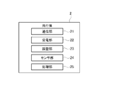
- FIG. 2 is a configuration diagram showing the configuration of the aircraft of this embodiment.
- FIG. 3 is an external view showing an example of the external appearance of the control device.
- 4 is a cross-sectional view of the control device shown in FIG. 3.
- FIG. 5 is an explanatory diagram showing communication between the control device and the aircraft.
- FIG. 6 is an explanatory diagram showing recovery of the flying object.
- FIG. 7 is an explanatory diagram showing power supply to an aircraft.
- FIG. 8 is an explanatory diagram showing data transmission to a communication satellite.
- FIG. 9 is an explanatory diagram showing power generation by the control device.
- FIG. 10 is a flowchart showing data transmission processing by the control device.
- FIG. 11 is a flow chart showing maritime data transmission processing by the flying object 2 .
- FIG. 12 is a hardware configuration example.
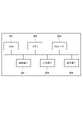
- FIG. 1 is a configuration diagram showing the configuration of the ocean monitoring system of this embodiment.
- the illustrated marine monitoring system comprises a controller 1 and at least one air vehicle 2 .
- the control device 1 is placed in the ocean, measures at least one environment under the sea and on the surface of the sea, and remotely controls the aircraft 2 .
- a buoy, a float, a ship, or the like may be used as the control device 1.
- the control device 1 may be a device that is moored and does not move, or it may be a device that can be moved with moving means.
- At least one flying object 2 is assigned to the control device 1, and the control device 1 controls one or more flying objects 2. It is assumed that the control device 1 of this embodiment controls a plurality of flying objects 2 .
- the control device 1 shown in FIG. 1 is The control device 1 shown in FIG.
- the power generation unit 11 includes a solar power generation unit 111 that uses solar energy and a vibration power generation unit 112 that uses wave vibration.
- the photovoltaic power generation unit 111 is arranged above the sea surface so as to be exposed to sunlight.
- the power storage unit 12 stores the electric power generated by the power generation unit 111 and the vibration power generation unit 112 .
- Control device 1 and flying object 2 are driven using power stored in power storage unit 12 .
- the sensor unit 13 measures (senses) at least one environment of the sea and the sea surface to acquire ocean data (first measurement data).
- the sensor unit 13 includes one or more sensors.
- the sensor unit 13 may include multiple sensors of different types.
- Marine data includes, for example, water temperature, water pressure, salinity, and the like.
- the sensor units 13 can be distributed and arranged at arbitrary positions (for example, above the sea surface, below the sea surface, etc.) of the control device 1 according to the object to be measured.
- the power supply unit 14 supplies the electric power of the power storage unit 12 to the aircraft 2 .
- the power supply unit 14 supplies power to the aircraft 2 in flight by radio wave transmission, and wirelessly supplies power to the aircraft waiting in the control device 1 .
- the power supply unit 14 includes a wireless power supply unit 141 that supplies power to the aircraft 2 in flight by radio wave transmission, and a non-contact power supply unit 142 that supplies power to the aircraft 2 on standby in a non-contact manner.
- the communication unit 15 (first communication unit) communicates with the aircraft 2 and the communication satellite 3 according to instructions from the control unit 16. For example, the communication unit 15 receives maritime data measured by the aircraft 2 and sends the received maritime data to the control unit 16 . The communication unit 15 transmits the control information instructed by the control unit 16 to the aircraft 2 . The communication unit 15 may communicate with the communication satellite 3 and transmit ocean data measured by itself and ocean data received from the aircraft 2 to the communication satellite 3 .
- the control unit 16 controls each unit 11 to 15 of the control device 1.
- the control unit 16 controls the flying object 2 by transmitting control information to the flying object 2 using the communication unit 15 .
- Control information is information for controlling and operating the aircraft 2 .
- the control information includes, for example, a flight instruction indicating the flight path of the flying object 2, a return instruction for returning the flying object 2 to the control device 1, and the like.
- control unit 16 controls the adjustment unit provided in the aircraft 2 or the control device 1 to shorten the length of the open portion of the wire. , the aircraft 2 may be recovered to the control device 1 .
- the adjustment section will be described later.
- the control unit 16 controls the sensor unit 13 and causes the sensor unit 13 to measure ocean data at an arbitrary timing.
- the control unit 16 acquires the measured ocean data and stores it in a storage device included in the control unit 16 .
- the control unit 16 may autonomously execute various processes such as control of the flying object 2 and acquisition of oceanographic data using the sensor unit 13. processing may be performed.
- the management device may be placed on the ground, for example, remotely access the control device 1 by wireless communication, and remotely operate the control device 1 . In this case, the management device can remotely control the aircraft 2 indirectly via the control device 1 .
- FIG. 2 is a diagram showing the configuration of the aircraft 2 of this embodiment.
- the aircraft 2 flies under the control of the control device 1 and measures the sea environment.
- the flying object 2 is an unmanned flying object, such as a drone.
- the illustrated flying object 2 includes a communication section 21 , a power receiving section 22 , an adjustment section 23 , a sensor section 24 and a processing section 25 .
- the communication unit 21 (second communication unit) communicates with the control device 1.
- the communication unit 21 receives control information transmitted by the control device 1 and transmits maritime data measured by the sensor unit 24 to the control device 1 .
- the communication unit 21 may communicate with the communication satellite 3 and directly transmit oceanographic data measured by the sensor unit 24 to the communication satellite 3 .
- the power receiving unit 22 receives power supplied from the control device 1 and drives the aircraft 2 using the power.
- the adjustment unit 23 adjusts the length of the open portion of the wire according to the control of the control device 1 when the control device 1 and the aircraft 2 are connected by a wire.
- the flying object 2 includes the adjusting section 23, but the control device 1 may include the adjusting section 23.
- the sensor unit 24 measures the sea environment (atmospheric environment) under the control of the control device 1 and acquires sea data (second measurement data).
- Sensor unit 24 includes one or more sensors.
- the sensor unit 24 may comprise multiple sensors of different types.
- Maritime data includes, for example, atmospheric temperature, humidity, carbon dioxide concentration, and the like.
- the processing unit 25 drives the flying object 2 according to the control of the control device 1.
- the processing unit 25 flies the aircraft 2 according to the control information transmitted by the control device 1 and causes the sensor unit 24 to measure sea data.
- the ocean monitoring system of the present embodiment combines the control device 1 that senses at least one of the ocean environments of the sea and the sea surface, and the flying object 2 that senses the sea.
- the control device 1 that senses at least one of the ocean environments of the sea and the sea surface
- the flying object 2 that senses the sea.
- control device 1 which is relatively easy to generate and store electricity, controls and manages the flying object 2, thereby extending the driving time of the flying object 2 and increasing the operating time of the flying object 2. It becomes possible to collect peripheral information in a wide range.
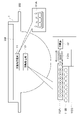
- FIG. 3 is an external view showing an example of the external appearance of the control device 1.
- the illustrated control device 1 includes a hemispherical lower layer portion 301 , a columnar middle layer portion 302 , and a columnar (tubular) upper layer portion 303 having a concave portion 304 .
- the concave portion 304 is a waiting area in which at least one flying object 2 can wait.
- the lower layer 301 is located in the sea
- the middle layer 302 and the upper layer 303 are located above the sea surface.
- the control device 1 is not limited to the shape of FIG. 3, but may have various other shapes.
- FIG. 4 is a cross-sectional view of the control device 1 shown in FIG.
- the solar power generation unit 111, the wireless power supply unit 141, the contactless power supply unit 142, and the communication unit 15 are arranged in the middle layer 302 and the upper layer 303 located above the sea surface. be.
- a vibration power generation unit 112 , a power storage unit 12 , a sensor unit 13 , and a control unit 16 are arranged in an underwater lower layer 301 .
- FIG. 4 is an example of the control device 1, and the arrangement of each part is not limited to this.
- FIG. 4 shows an aircraft 2A in flight, an aircraft 2B waiting in a standby area 304, and an aircraft 2C in flight connected to the control device 1 by a wire 4.
- FIG. 4 shows an aircraft 2A in flight, an aircraft 2B waiting in a standby area 304, and an aircraft 2C in flight connected to the control device 1 by a wire 4.
- FIG. 4 shows an aircraft 2A in flight, an aircraft 2B waiting in
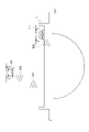
- FIG. 5 is an explanatory diagram showing communication between the control device 1 and the aircraft 2.
- the communication unit 15 of the control device 1 transmits control information 501 and 502 for controlling the flying object 2 to the flying objects 2A and 2B in accordance with instructions from the control unit 16, and transmits maritime data 503 measured by the flying object 2A. is received from the aircraft 2. Thereby, the control device 1 can operate the flying bodies 2A and 2B.
- the communication unit 15 provides, as the control information 501, to the aircraft 2A in flight, for example, an additional flight program, a flight instruction such as a return instruction to the control device 1, an instruction to acquire maritime data, and the like. Send. Further, the communication unit 15 waits in the control device 1 and transmits, as the control information 502, a flight instruction such as a flight program and an instruction to acquire maritime data, etc., to the aircraft 2B scheduled to fly.
- the flying object 2A transmits sea data 503 indicating the measured sea air environment to the control device 1 .
- the communication unit 15 of the control device 1 receives maritime data 503 transmitted by the aircraft 2A.
- the communication unit 15 can receive maritime data transmitted by each of a plurality of aircraft 2A. Also, the communication unit 15 can receive a plurality of different types of data transmitted from the aircraft 2A.
- the control unit 16 may store the maritime data received by the communication unit 15 in a memory or the like included in the control unit 16 and save it as backup data until it is transmitted to the communication satellite 3 .
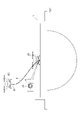
- FIG. 6 is an explanatory diagram showing recovery of the flying object 2.
- the flying object 2 includes an adjustment section 23 (wire reel) that adjusts the length of the open portion of the wire 4 .
- the adjuster 23 adjusts the length of the open portion of the wire 4 according to the distance between the controller 1 and the aircraft 2 when the aircraft 2 flies.
- the open portion is the length of the wire 4 that is not wound around the adjusting portion 23 and is adjusted to be longer than the distance between the control device 1 and the aircraft 2 .
- the control unit 16 of the control device 1 controls the adjusting unit 23 so that the flying object 2 can fly according to the flight command. For example, when flying the flying object 2 far from the control device 1 , the controller 16 instructs the adjuster 23 to pull out the wire 4 of a required length from the adjuster 23 .
- the control unit 16 instructs the adjustment unit 23 to wind the wire 4 so that the length of the open portion of the wire 4 is shortened. Thereby, the control unit 16 can return the flying object 2 in flight to the control device 1 .
- the flying object 2 is connected to the control device 1 by a wire 4, even if the flying object 2 breaks down during flight and stops, the wire 4 can be wound up to reach the standby area of the control device 1. The flying object 2 can be recovered.
- the control device 1 detects an abnormality of the flying object 2 and cuts off the wire 4. It is also possible to recover the flying object 2 by specifying it from the physical positional relationship and attaching a strong electromagnet to the tip of the wire 4 .
- the flying object 2 cannot fly as instructed by the control device 1, so it detects an abnormality and notifies the control device 1 of an error message.
- the controller 1 receives the error message, it sends an instruction to disconnect the wire 4 to the aircraft 2 , and the aircraft 2 disconnects the wire 4 .
- the tip of the wire 4 cut off from the aircraft 2 falls into the sea.
- the aircraft 2 also drops into the sea near the position where the tip of the wire 4 dropped.
- the control device 1 identifies the position information of the flying object 2 at the time of receiving the error message from the relative positional relationship with the control device 1, moves to the point where the flying object 2 would have fallen into the sea,
- a powerful electromagnet may be attached to the tip of the wire 4, and the flying object 2 may be retrieved using the magnetic force of the electromagnet.
- control device 1 can use the wire 4 to supply power to the aircraft 2 (cable power supply). That is, the control device 1 may use the wire 4 as the power supply section 14 .
- FIG. 7 is an explanatory diagram showing power feeding to the flying object 2.
- FIG. 7 shows two power feeding methods: wireless power feeding for radio wave transmission to an aircraft 2A in flight and contactless power feeding for non-contact power feeding to an aircraft 2B on standby in the control device 1.
- wireless power feeding for radio wave transmission to an aircraft 2A in flight and contactless power feeding for non-contact power feeding to an aircraft 2B on standby in the control device 1.
- the wireless power supply unit 141 uses microwaves 701 to supply power to the aircraft 2A in flight. At this time, the wireless power supply unit 141 can transmit power and signals to the aircraft 2 by modulating the microwave for power supply, and can communicate with the aircraft 2 . Namely. The wireless power supply unit 141 can transmit various control information to the aircraft 2 at the same time as power supply.
- the contactless power supply unit 142 can constantly supply power 702 contactlessly to the flying object 2B waiting in the control device 1 using electromagnetic induction, magnetic field resonance, electric field coupling, or the like.
- the wireless power supply unit 141 and the contactless power supply unit 142 can simultaneously supply power to a plurality of flying objects 2A and 2B.
- the wireless power supply unit 141 can realize simultaneous power supply to a plurality of flying objects 2A by using, for example, multi-beam forming.
- simultaneous power supply to a plurality of waiting flying objects 2B can be achieved.
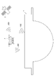
- FIG. 8 is an explanatory diagram showing data transmission to the communication satellite 3.
- the communication unit 21 of the aircraft 2 transmits sea data 801 measured by itself to the control device 1 .
- the communication unit 15 of the control device 1 transmits to the communication satellite 3 measurement data 802 including the ocean data measured by itself and the ocean data 801 received from the aircraft 2 . That is, the flying object 2 does not transmit the maritime data directly to the communication satellite 3, but rather transmits the maritime data to the control device 1 at a short distance, and the control device 1 sends the maritime data and the maritime data to the communication satellite 3 collectively. Send.
- the aircraft 2 can transmit maritime data to the control device 1 even when it is in flight or waiting in a waiting area.
- the communication unit 21 of the flying object 2 may communicate with the communication satellite 3 and directly transmit the maritime data 803 to the communication satellite 3.
- the control device 1 and the flying object 2 each transmit data measured by themselves to the communication satellite 3 .
- FIG. 9 is an explanatory diagram showing power generation by the control device 1.
- the photovoltaic power generation unit 111 is arranged at a position higher than the sea surface and generates power using the light energy of the sun.
- the solar power generation section 111 includes a small panel 111A arranged on the outer periphery of the standby area 304 (middle layer section 302). Electric power obtained during the day by the solar power generation unit 111 is sent to the power storage unit 112 .
- the vibration power generation unit 112 generates power by using vibrations caused by waves.
- the illustrated vibration power generation unit 112 (MEMS vibration power generation element) includes a movable electrode 112A, an electret 112B, a fixed electrode 112C, and a spring 112D. Generate power by changing the interval. Vibration power generation unit 112 uses vibration of waves, so that it can generate power all the time, and the obtained power is sent to power storage unit 112 .
- Electret 112B is a dielectric that retains a semi-permanent charge.
- the control device 1 of the present embodiment combines photovoltaic power generation, which can obtain a relatively large current but is difficult to generate power at night, and vibration power generation, which does not obtain a large amount of power but can generate power at all times of the day and night. power supply.
- FIG. 10 is a flowchart showing data transmission processing by the control device 1.
- the control device 1 measures at least one of the underwater environment and the sea surface environment to acquire oceanographic data (step S11).
- the control device 1 transmits control information to the flying object 2 and controls the flying object 2 (step S12). Note that the order of steps S11 and S12 may be reversed. Further, step S11 and step S12 may be performed at the same timing. That is, the control device 1 may control the flying object 2 while acquiring oceanographic data.
- the control device 1 receives the maritime data measured by the aircraft 2 from the aircraft 2 (step S13), and transmits the received maritime data and oceanographic data to the communication satellite 3 (step S14).
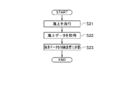
- FIG. 11 is a flowchart showing maritime data transmission processing by the flying object 2 .
- the aircraft 2 receives the control information from the control device 1 and flies over the sea according to the flight program designated by the control information (step S21).
- the flying object 2 measures the sea environment at the position and timing designated by the control information, and acquires sea data (step S22).
- the aircraft 2 transmits the measured maritime data to the control device 1 (step S23).
- the ocean monitoring system of the present embodiment described above comprises a control device 1 and at least one flying object 2.
- the control device 1 measures at least one environment of the sea and the sea surface, and is a sensor unit that acquires ocean data. 13, a control unit 16 that controls the flying object 2, and a communication unit 15 that receives sea data measured by the flying object 2.
- a sensor unit 24 for measuring and acquiring maritime data, and a communication unit 21 for transmitting the maritime data to the control device 1 are provided.
- control device 1 and the aircraft 2 can be easily managed with few resources.
- the control device 1 includes a power generation unit 111 and a power supply unit 112 to drive not only the control device 1 but also the aircraft 2 .
- a power generation unit 111 and a power supply unit 112 to drive not only the control device 1 but also the aircraft 2 .
- the control device 1 includes a power generation unit 111 and a power supply unit 112 to drive not only the control device 1 but also the aircraft 2 .
- control device 1 and the aircraft 2 are connected by a wire 4, the control device 1 or the aircraft 2 includes an adjustment section 23 for adjusting the length of the open portion of the wire 4, and the control section 16 controls the adjustment unit 23 to shorten the length of the open portion of the wire 4, thereby recovering the aircraft 2 to the control device 1.
- FIG. 1 When the flying object 2 is used for ocean sensing, there is a high possibility that the flying object 2 will be left in the sea if it becomes unusable due to dead battery or damage, but in this embodiment the flying object 2 can be recovered using the wire 4 Therefore, it can be said that the system is environmentally friendly.
- the communication unit 15 of the control device 1 transmits maritime data and maritime data received from the aircraft 2 to the communication satellite 3 .
- satellite data By combining satellite data with maritime data and oceanographic data, we can expect to ensure spatial and temporal completeness and high reliability of the data.
- IoT Internet of Things
- sensing will become more sophisticated as a global monitoring technology. can do. That is, by combining and interlocking the information transmitted from the control device 1 and the satellite data, it is possible to create high value-added monitoring information.
- various information measured by the control device 1 and the sensor units 13 and 24 of the aircraft 2 are collectively transmitted to the communication satellite 3.
- a general-purpose computer system as shown in FIG. 12 can be used.
- the illustrated computer system includes a CPU (Central Processing Unit: processor) 901 , memory 902 , storage 903 , communication device 904 , input device 905 and output device 906 .
- Memory 902 and storage 903 are storage devices.
- the functions of the control unit 16 and the communication unit 15 are realized by the CPU 901 executing the programs of the control unit 16 and the communication unit 15 loaded on the memory 902 .
- Programs for the control unit 16 and the communication unit 15 can be read by computers such as HDD (Hard Disk Drive), SSD (Solid State Drive), USB (Universal Serial Bus) memory, CD (Compact Disc), and DVD (Digital Versatile Disc). It can be stored on any available recording medium or distributed over a network.
- HDD Hard Disk Drive
- SSD Solid State Drive
- USB Universal Serial Bus
- CD Compact Disc
- DVD Digital Versatile Disc
- control device 11 power generation unit 111: solar power generation unit 112: vibration power generation unit 12: electricity storage unit 13: sensor unit (first measurement unit) 14: Power supply unit 141: Wireless power supply unit 142: Contactless power supply unit 15: Communication unit (first communication unit) 16: Control unit 2: Aircraft 21: Communication unit (second communication unit) 22: Power receiving unit 23: Adjusting unit 24: Sensor unit (second measuring unit) 25: Processing unit 3: Communication satellite 4: Wire
Landscapes
- Engineering & Computer Science (AREA)
- Aviation & Aerospace Engineering (AREA)
- Chemical & Material Sciences (AREA)
- Combustion & Propulsion (AREA)
- Mechanical Engineering (AREA)
- Environmental & Geological Engineering (AREA)
- Ocean & Marine Engineering (AREA)
- Life Sciences & Earth Sciences (AREA)
- Remote Sensing (AREA)
- Atmospheric Sciences (AREA)
- Computer Networks & Wireless Communication (AREA)
- Biodiversity & Conservation Biology (AREA)
- Ecology (AREA)
- Environmental Sciences (AREA)
- Radar, Positioning & Navigation (AREA)
- Physics & Mathematics (AREA)
- General Physics & Mathematics (AREA)
- Automation & Control Theory (AREA)
- Arrangements For Transmission Of Measured Signals (AREA)
Abstract
Description
11:発電部
111:太陽光発電部
112:振動発電部
12:蓄電部
13:センサ部(第1測定部)
14:給電部
141:無線給電部
142:無非接触給電部
15:通信部(第1通信部)
16:制御部
2 :飛行体
21:通信部(第2通信部)
22:受電部
23:調整部
24:センサ部(第2測定部)
25:処理部
3 :通信衛星
4 :ワイヤ
Claims (7)
- 制御装置と少なくとも1つの飛行体とを備える海洋モニタリングシステムであって、
前記制御装置は、
海中および海面の少なくとも1つの環境を測定し、第1測定データを取得する第1測定部と、
前記飛行体を制御する制御部と、
前記飛行体が測定した第2測定データを受信する第1通信部と、を備え、
前記飛行体は、
前記制御装置の制御に応じて海上の環境を測定し、前記第2測定データを取得する第2測定部と、
前記第2測定データを、前記制御装置に送信する第2通信部と、を備える
海洋モニタリングシステム。 - 前記第1通信部は、前記第1測定データと、前記飛行体から受信した前記第2測定データとを、通信衛星に送信する
請求項1に記載の海洋モニタリングシステム。 - 前記制御装置と前記飛行体とは、ワイヤで接続され、
前記制御装置または前記飛行体は、前記ワイヤの開放部分の長さを調整する調整部を備え、
前記制御部は、前記調整部を制御し、前記ワイヤの開放部分の長さを短くすることで、前記飛行体を前記制御装置に回収する
請求項1または2に記載の海洋モニタリングシステム。 - 前記制御装置は、
飛行中の前記飛行体に電波伝送で給電し、当該制御装置で待機する前記飛行体に非接触で給電する給電部を備える
請求項1から3のいずれか1項に記載の海洋モニタリングシステム。 - 前記制御装置は、
太陽光発電部と、
波の振動を利用した振動発電部と、を備える
請求項4に記載の海洋モニタリングシステム。 - 制御装置と少なくとも1つの飛行体とを備える海洋モニタリングシステムにおける、前記制御装置であって、
海中および海面の少なくとも1つの環境を測定し、第1測定データを取得する測定部と、
海上の環境を測定する前記飛行体を制御する制御部と、
前記飛行体が測定した第2測定データを、前記飛行体から受信する通信部と、を備える
制御装置。 - 制御装置と少なくとも1つの飛行体とを備える海洋モニタリングシステムが行う海洋モニタリング方法であって、
前記制御装置は、
海中および海面の少なくとも1つの環境を測定して第1測定データを取得するとともに、前記飛行体を制御するステップと、
前記飛行体が測定した第2測定データを受信するステップと、を行い、
前記飛行体は、
前記制御装置の制御に応じて海上の環境を測定し、前記第2測定データを取得するステップと、
前記第2測定データを、前記制御装置に送信するステップと、を行う
海洋モニタリング方法。
Priority Applications (3)
| Application Number | Priority Date | Filing Date | Title |
|---|---|---|---|
| JP2023514278A JPWO2022219781A1 (ja) | 2021-04-15 | 2021-04-15 | |
| US18/555,288 US20240201418A1 (en) | 2021-04-15 | 2021-04-15 | Marine monitoring system, control appratus and marine monitoring method |
| PCT/JP2021/015604 WO2022219781A1 (ja) | 2021-04-15 | 2021-04-15 | 海洋モニタリングシステム、制御装置、および海洋モニタリング方法 |
Applications Claiming Priority (1)
| Application Number | Priority Date | Filing Date | Title |
|---|---|---|---|
| PCT/JP2021/015604 WO2022219781A1 (ja) | 2021-04-15 | 2021-04-15 | 海洋モニタリングシステム、制御装置、および海洋モニタリング方法 |
Publications (1)
| Publication Number | Publication Date |
|---|---|
| WO2022219781A1 true WO2022219781A1 (ja) | 2022-10-20 |
Family
ID=83640251
Family Applications (1)
| Application Number | Title | Priority Date | Filing Date |
|---|---|---|---|
| PCT/JP2021/015604 Ceased WO2022219781A1 (ja) | 2021-04-15 | 2021-04-15 | 海洋モニタリングシステム、制御装置、および海洋モニタリング方法 |
Country Status (3)
| Country | Link |
|---|---|
| US (1) | US20240201418A1 (ja) |
| JP (1) | JPWO2022219781A1 (ja) |
| WO (1) | WO2022219781A1 (ja) |
Families Citing this family (3)
| Publication number | Priority date | Publication date | Assignee | Title |
|---|---|---|---|---|
| US12227303B2 (en) * | 2021-10-19 | 2025-02-18 | Tarkan Bastiyali | Air taxi pod terminals and methods |
| US20250089203A1 (en) * | 2023-09-13 | 2025-03-13 | Toyota Motor Engineering & Manufacturing North America, Inc. | Fluidic oscillators for the passive cooling of electronic devices |
| US12595083B1 (en) * | 2024-11-20 | 2026-04-07 | Blue Vigil Llc | Drone base |
Citations (4)
| Publication number | Priority date | Publication date | Assignee | Title |
|---|---|---|---|---|
| KR20170089589A (ko) * | 2016-01-27 | 2017-08-04 | 한국해양과학기술원 | 드론을 이용한 다중 해양 관측 시스템 |
| CN108248859A (zh) * | 2017-12-28 | 2018-07-06 | 上海交通大学 | 系留式海空多栖航行器系统 |
| JP2020021357A (ja) * | 2018-08-02 | 2020-02-06 | 古野電気株式会社 | 海上探索システム、無人飛行体、及び無人飛行方法 |
| JP2020196392A (ja) * | 2019-06-05 | 2020-12-10 | 三菱ロジスネクスト株式会社 | 無人飛行体用給電システム |
Family Cites Families (3)
| Publication number | Priority date | Publication date | Assignee | Title |
|---|---|---|---|---|
| US20190100108A1 (en) * | 2017-09-29 | 2019-04-04 | Qualcomm Incorporated | Robotic Vehicle Renewable Resource Charging Station Management Systems and Methods |
| JP7114716B2 (ja) * | 2018-01-03 | 2022-08-08 | ハダル, インコーポレイテッド | ブイおよびブイネットワークの段階的展開 |
| US11242145B2 (en) * | 2019-02-22 | 2022-02-08 | At&T Iniellectual Property I, L.P. | Artificial intelligence platform for mobile charging of rechargeable vehicles and robotic devices |
-
2021
- 2021-04-15 US US18/555,288 patent/US20240201418A1/en not_active Abandoned
- 2021-04-15 WO PCT/JP2021/015604 patent/WO2022219781A1/ja not_active Ceased
- 2021-04-15 JP JP2023514278A patent/JPWO2022219781A1/ja active Pending
Patent Citations (4)
| Publication number | Priority date | Publication date | Assignee | Title |
|---|---|---|---|---|
| KR20170089589A (ko) * | 2016-01-27 | 2017-08-04 | 한국해양과학기술원 | 드론을 이용한 다중 해양 관측 시스템 |
| CN108248859A (zh) * | 2017-12-28 | 2018-07-06 | 上海交通大学 | 系留式海空多栖航行器系统 |
| JP2020021357A (ja) * | 2018-08-02 | 2020-02-06 | 古野電気株式会社 | 海上探索システム、無人飛行体、及び無人飛行方法 |
| JP2020196392A (ja) * | 2019-06-05 | 2020-12-10 | 三菱ロジスネクスト株式会社 | 無人飛行体用給電システム |
Also Published As
| Publication number | Publication date |
|---|---|
| JPWO2022219781A1 (ja) | 2022-10-20 |
| US20240201418A1 (en) | 2024-06-20 |
Similar Documents
| Publication | Publication Date | Title |
|---|---|---|
| WO2022219781A1 (ja) | 海洋モニタリングシステム、制御装置、および海洋モニタリング方法 | |
| US10410788B1 (en) | Wireless power and data transfer for unmanned vehicles | |
| CN103926560B (zh) | 一种深海水声综合定位系统及其对水下潜器的定位与导航方法 | |
| US20150344109A1 (en) | Controllable buoys and networked buoy systems | |
| CN106840365B (zh) | 一种小型水下自主工作的光纤矢量水听器系统 | |
| US8867305B2 (en) | Method of assisting the deployment/retrieval of linear acoustic antennas towed by a vessel, during the course of which distance-measuring means carried by the antennas communicate with one another | |
| NO332115B1 (no) | Styringsinnretning for posisjonering av instrumentert tauet kabel i vann | |
| KR101910469B1 (ko) | 무선 다층 수중 환경 측정장치 | |
| Martínez de Alegría et al. | Wireless power transfer for unmanned underwater vehicles: Technologies, challenges and applications | |
| Manley et al. | Unmanned Surface Vessels (USVs) as tow platforms: Wave Glider experience and results | |
| JP6919033B2 (ja) | 送電装置 | |
| US20210004001A1 (en) | Information processing system | |
| US20160025883A1 (en) | Submerged hub for ocean bottom seismic data acquisition | |
| CN111010210B (zh) | 一种有缆的水下声学发射潜标及其方法 | |
| KR102445599B1 (ko) | 해상 조난자의 신속 탐색을 위한 구조용 통신 중계 부이 | |
| JP7675625B2 (ja) | 無人点検システムおよび無人点検方法 | |
| CN111212146A (zh) | 一种波浪滑翔器网络管理系统 | |
| JP6492651B2 (ja) | 給電システム、移動体および給電装置 | |
| Shah | Design considerations for engineering autonomous underwater vehicles | |
| KR101964139B1 (ko) | 장기체류형 소노글라이더 및 이의 동작 방법 | |
| US10152562B1 (en) | Submerged surveillance node | |
| WO2019240256A1 (ja) | 水中給電システム | |
| Kawada et al. | Acoustic positioning system of combined aerial and underwater drones | |
| Eubank et al. | Unattended operation of an autonomous seaplane for persistent surface and airborne ocean monitoring | |
| JP7549274B2 (ja) | センサ管理移動機、移動体管理拠点、及び環境情報収集システム |
Legal Events
| Date | Code | Title | Description |
|---|---|---|---|
| 121 | Ep: the epo has been informed by wipo that ep was designated in this application |
Ref document number: 21936977 Country of ref document: EP Kind code of ref document: A1 |
|
| WWE | Wipo information: entry into national phase |
Ref document number: 2023514278 Country of ref document: JP |
|
| WWE | Wipo information: entry into national phase |
Ref document number: 18555288 Country of ref document: US |
|
| NENP | Non-entry into the national phase |
Ref country code: DE |
|
| 122 | Ep: pct application non-entry in european phase |
Ref document number: 21936977 Country of ref document: EP Kind code of ref document: A1 |