WO2022219684A1 - 情報処理装置、短絡判定方法およびプログラム - Google Patents
情報処理装置、短絡判定方法およびプログラム Download PDFInfo
- Publication number
- WO2022219684A1 WO2022219684A1 PCT/JP2021/015218 JP2021015218W WO2022219684A1 WO 2022219684 A1 WO2022219684 A1 WO 2022219684A1 JP 2021015218 W JP2021015218 W JP 2021015218W WO 2022219684 A1 WO2022219684 A1 WO 2022219684A1
- Authority
- WO
- WIPO (PCT)
- Prior art keywords
- power supply
- fuse
- short circuit
- supply system
- calculated
- Prior art date
- Legal status (The legal status is an assumption and is not a legal conclusion. Google has not performed a legal analysis and makes no representation as to the accuracy of the status listed.)
- Ceased
Links
Images



Classifications
-
- H—ELECTRICITY
- H02—GENERATION; CONVERSION OR DISTRIBUTION OF ELECTRIC POWER
- H02J—ELECTRIC POWER NETWORKS; CIRCUIT ARRANGEMENTS OR SYSTEMS FOR SUPPLYING OR DISTRIBUTING ELECTRIC POWER; SYSTEMS FOR STORING ELECTRIC ENERGY
- H02J13/00—Circuit arrangements for providing remote monitoring or remote control of equipment in a power distribution network
Definitions
- the present invention relates to an information processing device, a short circuit determination method, and a program.
- a large-capacity electrolytic capacitor and fuse built into the current distribution device are used for short-circuit protection in an indoor DC power supply system (cable length of several hundred meters or less). In the event of a short circuit, electric charge is supplied from the large-capacity capacitor to the fuse, blowing the fuse. In an outdoor DC power supply system with a long cable length (about several thousand meters), a large-capacity capacitor cannot be used.
- Non-Patent Document 1 discloses a system design method that considers the effects of short-circuit faults in a high-voltage DC power supply system.
- the disclosed technology aims to support investigation of the cause when a failure occurs in the power supply system.
- the disclosed technology includes a data acquisition unit that acquires data indicating characteristics of a power supply system, and a short circuit possibility determination unit that determines the possibility of a short circuit occurring in the power supply system based on the data. It is an information processing device.
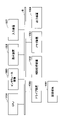
- FIG. 2 is a functional configuration diagram of an information processing device
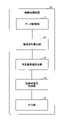
- FIG. 7 is a flowchart showing an example of the flow of short-circuit determination processing
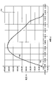
- FIG. 4 is a first diagram showing an example of current waveforms
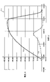
- FIG. 4B is a second diagram showing an example of a current waveform
- FIG. 1 is a diagram showing the system configuration of the power supply system to be determined.
- the power supply system 1 to be subjected to the determination process according to the present embodiment is an outdoor DC power supply system, and the cable length of the power supply cable is about several thousand meters.
- the power supply system 1 includes a rectifier (or AC/DC converter) 901 , a distribution board 902 , a DC/DC converter 903 , a fuse 906 , a cable impedance 907 and equipment 908 .
- the DC/DC converter 903 includes a gate block 904 and an X capacitor 905 .
- a DC power supply system for outdoor use cannot use a large-capacity capacitor like an indoor DC power supply system, so the fuse 906 is difficult to blow. Furthermore, as the cable length of the power supply cable increases, the cable impedance increases and the short-circuit current decreases, so there is a characteristic that the fuse 906 is less likely to blow.
- the DC/DC converter 903 has a function of detecting an overcurrent due to a short circuit or the like and opening the gate block 904 to stop power supply.
- the charge accumulated in the X capacitor 905 (about several hundred to several thousand uF/kW) incorporated in the output filter of the DC/DC converter 903 continues toward the short-circuit point. continue to flow.
- the current flowing from the X capacitor 905 may melt the fuse 906 .
- FIG. 2 is a functional configuration diagram of the information processing device.
- the information processing device 10 includes a data acquisition unit 11 , a current waveform calculation unit 12 , a determination reference value calculation unit 13 , a short circuit possibility determination unit 14 and an output unit 15 .
- the data acquisition unit 11 acquires data indicating characteristics of the power supply system 1 . Specifically, the data acquisition unit 11 obtains the operation time of the gate block 904 of the DC/DC converter 903 included in the power supply system 1, the capacity of the X capacitor 905 of the DC/DC converter 903, the impedance of the power supply cable, the power supply Data indicating the fusing characteristics of the fuse 906 included in the system 1 is acquired. The data acquisition unit 11 may acquire data by a user's input operation, or may receive data from another device or the like.
- the current waveform calculation unit 12 calculates the current waveform when the power supply system 1 is short-circuited based on the operation time of the gate block 904, the capacitance of the X capacitor 905, and the impedance of the power supply cable among the data acquired by the data acquisition unit 11. Calculate the current waveform.
- the current waveform calculator 12 detects the short circuit of the power supply system 1 based on the capacitance of the X capacitor 905 and the impedance of the power supply cable.
- the power feeding system 1 is calculated based on the capacitance of the X capacitor 905, the impedance of the power feeding cable, and the operating time of the gate block 904 Calculate the current waveform at the time of short circuit.
- the current waveform calculator 12 calculates the current waveform when the power supply system 1 is short-circuited by a simulation of a circuit equivalent to the power supply system 1 .
- the determination reference value calculator 13 calculates a reference value (determination reference value) for determining the possibility of a short circuit based on the current waveform calculated by the current waveform calculator 12 . Specifically, the determination reference value calculator 13 calculates the total amount of charge (It) flowing through the circuit at the time of short circuit and the Joule integral value (I 2 t).
- the short-circuit possibility determination unit 14 determines whether or not there is a possibility that a short-circuit has occurred based on the calculated determination reference value and the fusing characteristics of the fuse 906 . Specifically, the short-circuit possibility determination unit 14 determines that the calculated total amount of charge (It) exceeds the limit value of the total amount of charge obtained from the fusing characteristics of the fuse 906, or the Joule integral value (I 2 t ) exceeds the limit value of the Joule integral value obtained from the fusing characteristics of the fuse 906, it is determined whether or not there is a possibility that a short circuit has occurred.
- the output unit 15 outputs the determination result of the short circuit possibility determination unit 14 .
- the output unit 15 may transmit information indicating the determination result to another device, or may display a screen indicating the determination result.
- FIG. 3 is a flowchart showing an example of the flow of short circuit determination processing.
- the data acquisition unit 11 acquires data indicating the characteristics of the power supply system 1, which is an outdoor DC power supply system (step S101).
- the data indicating the characteristics of the power supply system 1 include the operation time of the gate block 904 of the DC/DC converter 903 included in the power supply system 1, the capacity of the X capacitor 905 of the DC/DC converter 903, the impedance of the power supply cable, and the power supply system. and fusing characteristics of the fuse 906 provided in 1.
- the current waveform calculator 12 determines whether or not the operation time of the gate block 904 is 100 ⁇ s or less (step S102). Note that 100 ⁇ s is a preset value as a predetermined threshold.
- the current waveform calculator 12 determines that the operation time of the gate block 904 is 100 ⁇ s or less (step S102: Yes), it calculates the current waveform (time constant) during a short circuit by simulation based on the capacitance of the capacitor and the cable impedance. (Step S103). This simulation is a simulation using an equivalent circuit to be described later.
- the determination reference value calculator 13 calculates the total amount of charge (It) flowing in the circuit at the time of short circuit and the Joule integral value (I 2 t) (step S104). Then, the short circuit possibility determination unit 14 determines that the calculated total charge amount is smaller than the limit value of the total charge amount obtained from the blowing characteristics of the fuse 906, or the calculated Joule integral value is obtained from the blowing characteristics of the fuse 906. It is determined whether or not it is smaller than the limit value of the Joule integral value (step S105).
- the short-circuit possibility determination unit 14 determines whether the calculated total charge amount is smaller than the limit value of the total charge amount obtained from the blowing characteristics of the fuse 906, or the calculated Joule integral value is the Joule integral obtained from the blowing characteristics of the fuse 906. If it is determined that the value is smaller than the limit value (step S105: Yes), it is determined that there is a possibility of short circuit (step S106).
- the short circuit possibility determination unit 14 determines that the calculated total charge amount is not smaller than the limit value of the total charge amount obtained from the blowing characteristic of the fuse 906 and the calculated Joule integral value is obtained from the blowing characteristic of the fuse 906. If it is determined that it is not smaller than the limit value of the Joule integral value obtained (step S105: No), it is determined that there is no possibility of a short circuit (step S107).
- step S102 when the current waveform calculation unit 12 determines that the operation time of the gate block 904 is not 100 ⁇ s or less (step S102: No), the simulation based on the capacitor capacity, the cable impedance, and the operation time of the gate block , the current waveform (time constant) at the time of short circuit is calculated (step S108).
- the determination reference value calculator 13 calculates the total amount of charge (It) flowing in the circuit at the time of short circuit and the Joule integral value (I 2 t) (step S109). Then, the short-circuit possibility determination unit 14 determines that the calculated total charge amount exceeds the limit value of the total charge amount obtained from the fusing characteristics of the fuse, and the calculated Joule integral value is obtained from the fusing characteristics of the fuse. It is determined whether or not the Joule integral value exceeds the limit value (step S110).
- the short-circuit possibility determination unit 14 determines that the calculated total charge amount exceeds the limit value of the total charge amount obtained from the fusing characteristics of the fuse, and the calculated Joule integral value exceeds the Joule integral obtained from the fusing characteristics of the fuse. If it is determined that the value exceeds the limit value (step S110: Yes), it is determined that there is no possibility of a short circuit (step S107).
- the short-circuit possibility determination unit 14 determines that the calculated total charge amount does not exceed the limit value of the total charge amount obtained from the fusing characteristics of the fuse, or the calculated Joule integral value is obtained from the fusing characteristics of the fuse. If it is determined that the Joule integral value does not exceed the limit value (step S110: No), it is determined as an error, and the error is displayed on the screen or the like (step S111). Then, returning to step S101, the data acquisition unit 11 acquires the corrected data.
- FIG. 4 is a diagram showing an outline of an equivalent circuit.
- Equivalent circuit 800 is used in steps S103 and S108 shown in FIG.
- the equivalent circuit 800 includes a DC/DC converter 803, a fuse 804, an RL series circuit 805, and a short-circuit switch 806.
- DC/DC converter 803 includes gate block 801 and X capacitor 802 .
- step S103 the current waveform calculator 12 calculates the total charges It and I 2 t flowing through the fuse 804 without considering the operation time of the gate block because the operation time of the gate block is short.
- step S108 the current waveform calculator 12 assumes that the charge from the X capacitor 802 and the charge from the gate block 801 flow to the fuse 804 because the operation time of the gate block is long.
- the total amount of charge It and I 2 t flowing through the fuse 804 is calculated according to the operation time of the block.
- FIG. 5 is a first diagram showing an example of a current waveform.
- a graph 701 is an example of the current waveform calculated in step S103.
- a current waveform 702 representing the current flowing through the fuse 804 and a current waveform 703 representing the current flowing through the gate block 801 are shown. In this case, almost no current flows through the gate block 801 , so the current waveform 702 matches the current waveform representing the current flowing through the X capacitor 802 .
- FIG. 6 is a second diagram showing an example of the current waveform.
- a graph 711 is an example of the current waveform calculated in step S108.
- a current waveform 712 representing the current flowing through the fuse 804 and a current waveform 713 representing the current flowing through the gate block 801 are shown.
- the current waveform representing the sum of the current flowing through the X capacitor 802 and the current flowing through the gate block 801 is the current waveform representing the current flowing through the fuse 804 .
- the information processing apparatus 10 in an outdoor DC power supply system with a long cable length, when only the gate block of the DC/DC converter is stopped and the fuse is not cut, short circuit is possible. determine the presence or absence of gender. This can assist in determining the cause of the DC/DC converter failure or short circuit.
- the information processing apparatus 10 can be realized, for example, by causing a computer to execute a program describing the processing details described in the present embodiment.
- this "computer” may be a physical machine or a virtual machine on the cloud.
- the "hardware” described here is virtual hardware.
- the above program can be recorded on a computer-readable recording medium (portable memory, etc.), saved, or distributed. It is also possible to provide the above program through a network such as the Internet or e-mail.
- FIG. 7 is a diagram showing a hardware configuration example of the computer.
- the computer of FIG. 7 has a drive device 1000, an auxiliary storage device 1002, a memory device 1003, a CPU 1004, an interface device 1005, a display device 1006, an input device 1007, an output device 1008, etc., which are connected to each other via a bus B, respectively.
- a program that implements the processing in the computer is provided by a recording medium 1001 such as a CD-ROM or memory card, for example.
- a recording medium 1001 such as a CD-ROM or memory card
- the program is installed from the recording medium 1001 to the auxiliary storage device 1002 via the drive device 1000 .
- the program does not necessarily need to be installed from the recording medium 1001, and may be downloaded from another computer via the network.
- the auxiliary storage device 1002 stores installed programs, as well as necessary files and data.
- the memory device 1003 reads and stores the program from the auxiliary storage device 1002 when a program activation instruction is received.
- the CPU 1004 implements functions related to the device according to programs stored in the memory device 1003 .
- the interface device 1005 is used as an interface for connecting to the network.
- a display device 1006 displays a GUI (Graphical User Interface) or the like by a program.
- An input device 1007 is composed of a keyboard, a mouse, buttons, a touch panel, or the like, and is used to input various operational instructions.
- the output device 1008 outputs the calculation result.
- This specification describes at least an information processing device, a short-circuit determination method, and a program described in each of the following items.
- (Section 1) a data acquisition unit that acquires data indicating characteristics of the power supply system; a short circuit possibility determination unit that determines whether or not there is a possibility that a short circuit has occurred in the power supply system based on the data; Information processing equipment.
- (Section 2) The data acquisition unit obtains the operation time of the gate block of the DC/DC converter provided in the power supply system, the capacity of the X capacitor of the DC/DC converter, the impedance of the power supply cable, and the fusing characteristics of the fuse provided in the power supply system. and obtaining said data indicative of The information processing device according to item 1.
- (Section 3) a current waveform calculator that calculates a current waveform when the power supply system is short-circuited based on the operation time of the gate block, the capacitance of the X capacitor, and the impedance of the power supply cable; a determination reference value calculation unit that calculates the amount of charge (It) or Joule integral value (I 2 t) flowing in the circuit at the time of a short circuit based on the calculated current waveform, The short circuit possibility determination unit determines whether or not the short circuit has occurred based on the calculated amount of charge or the Joule integral value and the fusing characteristics of the fuse.
- the information processing device according to Item 2.
- the current waveform calculator calculates a current waveform when the power supply system is short-circuited based on the capacitance of the X capacitor and the impedance of the power supply cable. is calculated, and if the operation time of the gate block exceeds the threshold, the short circuit of the power supply system based on the capacitance of the X capacitor, the impedance of the power supply cable, and the operation time of the gate block calculating the current waveform at time;
- the information processing device according to Item 3.
- the determination reference value calculation unit calculates the charge amount and the Joule integral value, The short circuit possibility determination unit When the operation time of the gate block is equal to or less than the threshold, When the calculated charge amount is smaller than the limit value of the charge amount obtained from the fusing characteristic of the fuse, or when the calculated Joule integral value is smaller than the limit value of the Joule integral value obtained from the fusing characteristic of the fuse Then, if it is determined that there is a possibility of a short circuit, and the calculated charge amount is not smaller than the limit value of the charge amount obtained from the fusing characteristics of the fuse, and the calculated Joule integral value of the fuse is If it is not smaller than the limit value of the Joule integral value obtained from the fusing characteristic, it is determined that there is no possibility of short circuit, If the operating time of the gate block exceeds the threshold, When the calculated charge amount exceeds a limit value of the charge amount obtained from the fusing characteristics of the fuse, and the calculated Joule integral value is a limit value of the
- the information processing device determines whether it exceeds, it is determined that there is no possibility of a short circuit, and if the calculated charge amount does not exceed the limit value of the charge amount obtained from the fusing characteristics of the fuse, or the calculated Joule integral determining an error when the value does not exceed the limit value of the Joule integral value obtained from the fusing characteristics of the fuse;
- the information processing device according to Item 4. (Section 6)
- the current waveform calculation unit calculates the current waveform when the power supply system is short-circuited by simulation in a circuit equivalent to the power supply system.
- the information processing apparatus according to any one of items 3 to 5.
- (Section 7) A computer implemented method comprising: obtaining data characterizing the power supply system; determining whether there is a possibility that a short circuit has occurred in the power supply system based on the data; Short circuit judgment method. (Section 8) A program for causing a computer to function as each unit in the information processing apparatus according to any one of items 1 to 6.
Landscapes
- Engineering & Computer Science (AREA)
- Power Engineering (AREA)
- Emergency Protection Circuit Devices (AREA)
Abstract
給電システムの特性を示すデータを取得するデータ取得部と、前記データに基づいて、前記給電システムに短絡が発生した可能性の有無を判定する短絡可能性判定部と、を備える情報処理装置である。
Description
本発明は、情報処理装置、短絡判定方法およびプログラムに関する。
屋内用の直流給電システム(ケーブル亘長が数100m以下)での短絡保護には電流分配装置に内蔵された大容量電解コンデンサとヒューズが用いられる。短絡時には大容量コンデンサからヒューズに電荷が供給され、ヒューズが溶断する。ケーブル亘長が長い(数1000m程度)屋外用の直流給電システムでは大容量コンデンサが利用できず、DC/DCコンバータのゲートブロックとヒューズの2段で短絡保護を行う。
非特許文献1には、高電圧の直流給電システムにおいて、短絡故障による影響を考慮したシステムの設計方法が開示されている。
「高電圧直流給電システムの実現に向けて」,NTT技術ジャーナル,2009年8月,[online],インターネット<URL:https://www.ntt.co.jp/journal/0908/files/jn200908018.pdf>
従来の技術では、屋外用の直流給電システム等のように、ケーブル亘長が長い直流給電システムにおいては、DC/DCコンバータのゲートブロックのみが停止しヒューズが遮断していない場合、DC/DCコンバータの故障なのか短絡なのかの判別が困難であり、原因究明に時間を要するという問題がある。
開示の技術は、給電システムに故障が発生した場合の原因究明を支援することを目的とする。
開示の技術は、給電システムの特性を示すデータを取得するデータ取得部と、前記データに基づいて、前記給電システムに短絡が発生した可能性の有無を判定する短絡可能性判定部と、を備える情報処理装置である。
給電システムに故障が発生した場合の原因究明を支援することができる。
以下、図面を参照して本発明の実施の形態(本実施の形態)を説明する。以下で説明する実施の形態は一例に過ぎず、本発明が適用される実施の形態は、以下の実施の形態に限られるわけではない。
図1は、判定対象の給電システムのシステム構成を示す図である。
本実施の形態に係る判定処理の対象となる給電システム1は、屋外用の直流給電システムであって、給電ケーブルのケーブル亘長が数1000m程度のシステムである。給電システム1は、整流装置(またはAC/DCコンバータ)901と、分電盤902と、DC/DCコンバータ903と、ヒューズ906と、ケーブルインピーダンス907と、機器908と、を備える。
また、DC/DCコンバータ903は、ゲートブロック904と、Xコンデンサ905と、を備える。
屋外用の直流給電システムは、屋内用の直流給電システムのような大容量のコンデンサを使用できないため、ヒューズ906が切れにくい。さらに給電ケーブルのケーブル亘長が長くなると、ケーブルインピーダンスが増大し、短絡電流が小さくなるため、ヒューズ906が切れにくくなるという特性がある。
また、DC/DCコンバータ903は、短絡などで過電流が流れたことを検出し、ゲートブロック904を開放して給電を停止する機能がある。しかし、ゲートブロック904が開放された後も、DC/DCコンバータ903の出力フィルタに組み込まれているXコンデンサ905(数百~数千uF/kW程度)に蓄えられた電荷が、短絡点に向かって流れ続ける。これにより、ゲートブロック904が早く動作してもXコンデンサ905から流れる電流でヒューズ906が溶断することがある。
以下、このような状況においてゲートブロック904が停止し、ヒューズ906が溶断していない状況において、本実施の形態に係る情報処理装置を使用して、短絡が発生した可能性の有無を判定する方法について、説明する。
図2は、情報処理装置の機能構成図である。
情報処理装置10は、データ取得部11と、電流波形算出部12と、判定基準値算出部13と、短絡可能性判定部14と、出力部15と、を備える。
データ取得部11は、給電システム1の特性を示すデータを取得する。具体的には、データ取得部11は、給電システム1が備えるDC/DCコンバータ903のゲートブロック904の動作時間と、DC/DCコンバータ903のXコンデンサ905の容量と、給電ケーブルのインピーダンスと、給電システム1が備えるヒューズ906の溶断特性と、を示すデータを取得する。データ取得部11は、ユーザの入力操作によってデータを取得しても良いし、他の装置等からデータを受信しても良い。
電流波形算出部12は、データ取得部11が取得したデータのうち、ゲートブロック904の動作時間と、Xコンデンサ905の容量と、給電ケーブルのインピーダンスと、に基づいて、給電システム1の短絡時における電流波形を算出する。
具体的には、電流波形算出部12は、ゲートブロック904の動作時間が所定の閾値以下の場合には、Xコンデンサ905の容量と、給電ケーブルのインピーダンスと、に基づいて、給電システム1の短絡時における電流波形を算出し、ゲートブロック904の動作時間が閾値を超える場合には、Xコンデンサ905の容量と、給電ケーブルのインピーダンスと、ゲートブロック904の動作時間と、に基づいて、給電システム1の短絡時における電流波形を算出する。
なお、電流波形算出部12は、給電システム1と等価な回路におけるシミュレーションによって、給電システム1の短絡時における電流波形を算出する。
判定基準値算出部13は、電流波形算出部12によって算出された電流波形に基づいて、短絡の可能性を判定するための基準となる値(判定基準値)を算出する。具体的には、判定基準値算出部13は、短絡時に回路に流れる総電荷量(It)及びジュール積分値(I2t)を計算する。
短絡可能性判定部14は、算出された判定基準値と、ヒューズ906の溶断特性と、に基づいて、短絡が発生した可能性の有無を判定する。具体的には、短絡可能性判定部14は、算出された総電荷量(It)がヒューズ906の溶断特性から得られる総電荷量の限界値を超えている、またはジュール積分値(I2t)が、ヒューズ906の溶断特性から得られるジュール積分値の限界値を超えているか否かによって、短絡が発生した可能性の有無を判定する。
出力部15は、短絡可能性判定部14の判定結果を出力する。出力部15は、判定結果を示す情報を他の装置に送信しても良いし、判定結果を示す画面を表示しても良い。
(情報処理装置10の動作)
次に、情報処理装置10の動作について説明する。図3は、短絡判定処理の流れの一例を示すフローチャートである。
次に、情報処理装置10の動作について説明する。図3は、短絡判定処理の流れの一例を示すフローチャートである。
給電システム1に故障が発生した場合に、給電システム1の管理者等のユーザによる操作を受けて、短絡判定処理を開始する。
データ取得部11は、屋外直流給電システムである給電システム1の特性を示すデータを取得する(ステップS101)。給電システム1の特性を示すデータは、給電システム1が備えるDC/DCコンバータ903のゲートブロック904の動作時間と、DC/DCコンバータ903のXコンデンサ905の容量と、給電ケーブルのインピーダンスと、給電システム1が備えるヒューズ906の溶断特性と、を含む。
次に、電流波形算出部12は、ゲートブロック904の動作時間が100μs以下であるか否かを判定する(ステップS102)。なお、100μsは、所定の閾値として、あらかじめ設定された値である。
電流波形算出部12は、ゲートブロック904の動作時間が100μs以下であると判定すると(ステップS102:Yes)、コンデンサ容量とケーブルインピーダンスに基づくシミュレーションによって、短絡時の電流波形(時定数)を算出する(ステップS103)。このシミュレーションは、後述する等価回路によるシミュレーションである。
次に、判定基準値算出部13は、短絡時に回路に流れる総電荷量(It)及びジュール積分値(I2t)を計算する(ステップS104)。そして、短絡可能性判定部14は、計算された総電荷量がヒューズ906の溶断特性から得られる総電荷量の限界値より小さい、または計算されたジュール積分値がヒューズ906の溶断特性から得られるジュール積分値の限界値より小さいか否かを判定する(ステップS105)。
短絡可能性判定部14は、計算された総電荷量がヒューズ906の溶断特性から得られる総電荷量の限界値より小さい、または計算されたジュール積分値がヒューズ906の溶断特性から得られるジュール積分値の限界値より小さいと判定すると(ステップS105:Yes)、短絡の可能性があると判定する(ステップS106)。
また、短絡可能性判定部14は、計算された総電荷量がヒューズ906の溶断特性から得られる総電荷量の限界値より小さくない、かつ計算されたジュール積分値がヒューズ906の溶断特性から得られるジュール積分値の限界値より小さくないと判定すると(ステップS105:No)、短絡の可能性がないと判定する(ステップS107)。
また、ステップS102の処理において、電流波形算出部12は、ゲートブロック904の動作時間が100μs以下でないと判定すると(ステップS102:No)、コンデンサ容量、ケーブルインピーダンスおよびゲートブロックの動作時間に基づくシミュレーションによって、短絡時の電流波形(時定数)を算出する(ステップS108)。
続いて、判定基準値算出部13は、短絡時に回路に流れる総電荷量(It)及びジュール積分値(I2t)を計算する(ステップS109)。そして、短絡可能性判定部14は、計算された総電荷量がヒューズの溶断特性から得られる総電荷量の限界値を超えている、かつ計算されたジュール積分値がヒューズの溶断特性から得られるジュール積分値の限界値を超えているか否かを判定する(ステップS110)。
短絡可能性判定部14は、計算された総電荷量がヒューズの溶断特性から得られる総電荷量の限界値を超えている、かつ計算されたジュール積分値がヒューズの溶断特性から得られるジュール積分値の限界値を超えていると判定すると(ステップS110:Yes)、短絡の可能性がないと判定する(ステップS107)。
また、短絡可能性判定部14は、計算された総電荷量がヒューズの溶断特性から得られる総電荷量の限界値を超えていない、または計算されたジュール積分値がヒューズの溶断特性から得られるジュール積分値の限界値を超えていないと判定すると(ステップS110:No)、エラーと判定し、画面等にエラーを表示する(ステップS111)。そして、ステップS101に戻り、データ取得部11は、修正されたデータを取得する。
図4は、等価回路の概要を示す図である。等価回路800は、図3に示したステップS103およびステップS108において使用される。
等価回路800は、DC/DCコンバータ803と、ヒューズ804と、RL直列回路805と、短絡スイッチ806と、を備える。DC/DCコンバータ803は、ゲートブロック801と、Xコンデンサ802と、を備える。
電流波形算出部12は、ステップS103においては、ゲートブロックの動作時間が短いことから、ゲートブロックの動作時間を考慮せず、ヒューズ804に流れる総電荷量ItおよびI2tを計算する。
また、電流波形算出部12は、ステップS108においては、ゲートブロックの動作時間が長いことから、Xコンデンサ802からの電荷とゲートブロック801からの電荷が、ヒューズ804に流れることを想定して、ゲートブロックの動作時間に応じて、ヒューズ804に流れる総電荷量ItおよびI2tを計算する。
図5は、電流波形の一例を示す第一の図である。
グラフ701は、ステップS103において算出される電流波形の一例である。ヒューズ804に流れる電流を示す電流波形702と、ゲートブロック801を流れる電流を示す電流波形703と、が示される。この場合、ゲートブロック801を流れる電流はほとんど無いため、電流波形702がXコンデンサ802に流れる電流を示す電流波形と一致する。
図6は、電流波形の一例を示す第二の図である。
グラフ711は、ステップS108において算出される電流波形の一例である。ヒューズ804に流れる電流を示す電流波形712と、ゲートブロック801を流れる電流を示す電流波形713と、が示される。この場合、Xコンデンサ802を流れる電流と、ゲートブロック801に流れる電流と、を加算した電流を示す電流波形が、ヒューズ804に流れる電流を示す電流波形となる。
本実施の形態に係る情報処理装置10によれば、ケーブル亘長が長い屋外用の直流給電システムにおいて、DC/DCコンバータのゲートブロックのみが停止しヒューズが遮断していない場合に、短絡の可能性の有無を判定する。これによって、DC/DCコンバータの故障なのか短絡なのかの原因究明を支援することができる。
(情報処理装置10のハードウェア構成例)
情報処理装置10は、例えば、コンピュータに、本実施の形態で説明する処理内容を記述したプログラムを実行させることにより実現可能である。なお、この「コンピュータ」は、物理マシンであってもよいし、クラウド上の仮想マシンであってもよい。仮想マシンを使用する場合、ここで説明する「ハードウェア」は仮想的なハードウェアである。
情報処理装置10は、例えば、コンピュータに、本実施の形態で説明する処理内容を記述したプログラムを実行させることにより実現可能である。なお、この「コンピュータ」は、物理マシンであってもよいし、クラウド上の仮想マシンであってもよい。仮想マシンを使用する場合、ここで説明する「ハードウェア」は仮想的なハードウェアである。
上記プログラムは、コンピュータが読み取り可能な記録媒体(可搬メモリ等)に記録して、保存したり、配布したりすることが可能である。また、上記プログラムをインターネットや電子メール等、ネットワークを通して提供することも可能である。
図7は、上記コンピュータのハードウェア構成例を示す図である。図7のコンピュータは、それぞれバスBで相互に接続されているドライブ装置1000、補助記憶装置1002、メモリ装置1003、CPU1004、インタフェース装置1005、表示装置1006、入力装置1007、出力装置1008等を有する。
当該コンピュータでの処理を実現するプログラムは、例えば、CD-ROM又はメモリカード等の記録媒体1001によって提供される。プログラムを記憶した記録媒体1001がドライブ装置1000にセットされると、プログラムが記録媒体1001からドライブ装置1000を介して補助記憶装置1002にインストールされる。但し、プログラムのインストールは必ずしも記録媒体1001より行う必要はなく、ネットワークを介して他のコンピュータよりダウンロードするようにしてもよい。補助記憶装置1002は、インストールされたプログラムを格納すると共に、必要なファイルやデータ等を格納する。
メモリ装置1003は、プログラムの起動指示があった場合に、補助記憶装置1002からプログラムを読み出して格納する。CPU1004は、メモリ装置1003に格納されたプログラムに従って、当該装置に係る機能を実現する。インタフェース装置1005は、ネットワークに接続するためのインタフェースとして用いられる。表示装置1006はプログラムによるGUI(Graphical User Interface)等を表示する。入力装置1007はキーボード及びマウス、ボタン、又はタッチパネル等で構成され、様々な操作指示を入力させるために用いられる。出力装置1008は演算結果を出力する。
(実施の形態のまとめ)
本明細書には、少なくとも下記の各項に記載した情報処理装置、短絡判定方法およびプログラムが記載されている。
(第1項)
給電システムの特性を示すデータを取得するデータ取得部と、
前記データに基づいて、前記給電システムに短絡が発生した可能性の有無を判定する短絡可能性判定部と、を備える、
情報処理装置。
(第2項)
前記データ取得部は、前記給電システムが備えるDC/DCコンバータのゲートブロックの動作時間と、前記DC/DCコンバータのXコンデンサの容量と、給電ケーブルのインピーダンスと、前記給電システムが備えるヒューズの溶断特性と、を示す前記データを取得する、
第1項に記載の情報処理装置。
(第3項)
前記ゲートブロックの動作時間と、前記Xコンデンサの容量と、前記給電ケーブルのインピーダンスと、に基づいて、前記給電システムの短絡時における電流波形を算出する電流波形算出部と、
算出された前記電流波形に基づいて、短絡時に回路に流れる電荷量(It)またはジュール積分値(I2t)を算出する判定基準値算出部と、をさらに備え、
前記短絡可能性判定部は、算出された前記電荷量または前記ジュール積分値と、前記ヒューズの溶断特性と、に基づいて、前記短絡が発生した可能性の有無を判定する、
第2項に記載の情報処理装置。
(第4項)
前記電流波形算出部は、前記ゲートブロックの動作時間が所定の閾値以下の場合には、前記Xコンデンサの容量と、前記給電ケーブルのインピーダンスと、に基づいて、前記給電システムの短絡時における電流波形を算出し、前記ゲートブロックの動作時間が前記閾値を超える場合には、前記Xコンデンサの容量と、前記給電ケーブルのインピーダンスと、前記ゲートブロックの動作時間と、に基づいて、前記給電システムの短絡時における前記電流波形を算出する、
第3項に記載の情報処理装置。
(第5項)
前記判定基準値算出部は、前記電荷量および前記ジュール積分値を算出し、
前記短絡可能性判定部は、
前記ゲートブロックの動作時間が前記閾値以下の場合には、
算出された前記電荷量が前記ヒューズの溶断特性から得られる電荷量の限界値より小さい場合、または算出された前記ジュール積分値が前記ヒューズの溶断特性から得られるジュール積分値の限界値より小さい場合に、短絡の可能性があると判定し、算出された前記電荷量が前記ヒューズの溶断特性から得られる前記電荷量の限界値より小さくない場合、かつ算出された前記ジュール積分値が前記ヒューズの溶断特性から得られる前記ジュール積分値の限界値より小さくない場合に、短絡の可能性がないと判定し、
前記ゲートブロックの動作時間が前記閾値を超える場合には、
算出された前記電荷量が前記ヒューズの溶断特性から得られる前記電荷量の限界値を超えている場合かつ算出された前記ジュール積分値が前記ヒューズの溶断特性から得られる前記ジュール積分値の限界値を超えている場合に、短絡の可能性がないと判定し、算出された前記電荷量が前記ヒューズの溶断特性から得られる前記電荷量の限界値を超えていない場合または算出された前記ジュール積分値が前記ヒューズの溶断特性から得られる前記ジュール積分値の限界値を超えていない場合に、エラーと判定する、
第4項に記載の情報処理装置。
(第6項)
前記電流波形算出部は、前記給電システムと等価な回路におけるシミュレーションによって、前記給電システムの短絡時における前記電流波形を算出する、
第3項から第5項のいずれか1項に記載の情報処理装置。
(第7項)
コンピュータが実行する方法であって、
給電システムの特性を示すデータを取得するステップと、
前記データに基づいて、前記給電システムに短絡が発生した可能性の有無を判定するステップと、を備える、
短絡判定方法。
(第8項)
コンピュータを第1項から第6項のいずれか1項に記載の情報処理装置における各部として機能させるためのプログラム。
本明細書には、少なくとも下記の各項に記載した情報処理装置、短絡判定方法およびプログラムが記載されている。
(第1項)
給電システムの特性を示すデータを取得するデータ取得部と、
前記データに基づいて、前記給電システムに短絡が発生した可能性の有無を判定する短絡可能性判定部と、を備える、
情報処理装置。
(第2項)
前記データ取得部は、前記給電システムが備えるDC/DCコンバータのゲートブロックの動作時間と、前記DC/DCコンバータのXコンデンサの容量と、給電ケーブルのインピーダンスと、前記給電システムが備えるヒューズの溶断特性と、を示す前記データを取得する、
第1項に記載の情報処理装置。
(第3項)
前記ゲートブロックの動作時間と、前記Xコンデンサの容量と、前記給電ケーブルのインピーダンスと、に基づいて、前記給電システムの短絡時における電流波形を算出する電流波形算出部と、
算出された前記電流波形に基づいて、短絡時に回路に流れる電荷量(It)またはジュール積分値(I2t)を算出する判定基準値算出部と、をさらに備え、
前記短絡可能性判定部は、算出された前記電荷量または前記ジュール積分値と、前記ヒューズの溶断特性と、に基づいて、前記短絡が発生した可能性の有無を判定する、
第2項に記載の情報処理装置。
(第4項)
前記電流波形算出部は、前記ゲートブロックの動作時間が所定の閾値以下の場合には、前記Xコンデンサの容量と、前記給電ケーブルのインピーダンスと、に基づいて、前記給電システムの短絡時における電流波形を算出し、前記ゲートブロックの動作時間が前記閾値を超える場合には、前記Xコンデンサの容量と、前記給電ケーブルのインピーダンスと、前記ゲートブロックの動作時間と、に基づいて、前記給電システムの短絡時における前記電流波形を算出する、
第3項に記載の情報処理装置。
(第5項)
前記判定基準値算出部は、前記電荷量および前記ジュール積分値を算出し、
前記短絡可能性判定部は、
前記ゲートブロックの動作時間が前記閾値以下の場合には、
算出された前記電荷量が前記ヒューズの溶断特性から得られる電荷量の限界値より小さい場合、または算出された前記ジュール積分値が前記ヒューズの溶断特性から得られるジュール積分値の限界値より小さい場合に、短絡の可能性があると判定し、算出された前記電荷量が前記ヒューズの溶断特性から得られる前記電荷量の限界値より小さくない場合、かつ算出された前記ジュール積分値が前記ヒューズの溶断特性から得られる前記ジュール積分値の限界値より小さくない場合に、短絡の可能性がないと判定し、
前記ゲートブロックの動作時間が前記閾値を超える場合には、
算出された前記電荷量が前記ヒューズの溶断特性から得られる前記電荷量の限界値を超えている場合かつ算出された前記ジュール積分値が前記ヒューズの溶断特性から得られる前記ジュール積分値の限界値を超えている場合に、短絡の可能性がないと判定し、算出された前記電荷量が前記ヒューズの溶断特性から得られる前記電荷量の限界値を超えていない場合または算出された前記ジュール積分値が前記ヒューズの溶断特性から得られる前記ジュール積分値の限界値を超えていない場合に、エラーと判定する、
第4項に記載の情報処理装置。
(第6項)
前記電流波形算出部は、前記給電システムと等価な回路におけるシミュレーションによって、前記給電システムの短絡時における前記電流波形を算出する、
第3項から第5項のいずれか1項に記載の情報処理装置。
(第7項)
コンピュータが実行する方法であって、
給電システムの特性を示すデータを取得するステップと、
前記データに基づいて、前記給電システムに短絡が発生した可能性の有無を判定するステップと、を備える、
短絡判定方法。
(第8項)
コンピュータを第1項から第6項のいずれか1項に記載の情報処理装置における各部として機能させるためのプログラム。
以上、本実施の形態について説明したが、本発明はかかる特定の実施形態に限定されるものではなく、特許請求の範囲に記載された本発明の要旨の範囲内において、種々の変形・変更が可能である。
1 給電システム
10 情報処理装置
11 データ取得部
12 電流波形算出部
13 判定基準値算出部
14 短絡可能性判定部
15 出力部
801 ゲートブロック
802 Xコンデンサ
803 DC/DCコンバータ
804 ヒューズ
805 RL直列回路
806 短絡スイッチ
901 整流装置(またはAC/DCコンバータ)
902 分電盤
903 DC/DCコンバータ
904 ゲートブロック
905 Xコンデンサ
906 ヒューズ
907 ケーブルインピーダンス
908 機器
1000 ドライブ装置
1001 記録媒体
1002 補助記憶装置
1003 メモリ装置
1004 CPU
1005 インタフェース装置
1006 表示装置
1007 入力装置
1008 出力装置
10 情報処理装置
11 データ取得部
12 電流波形算出部
13 判定基準値算出部
14 短絡可能性判定部
15 出力部
801 ゲートブロック
802 Xコンデンサ
803 DC/DCコンバータ
804 ヒューズ
805 RL直列回路
806 短絡スイッチ
901 整流装置(またはAC/DCコンバータ)
902 分電盤
903 DC/DCコンバータ
904 ゲートブロック
905 Xコンデンサ
906 ヒューズ
907 ケーブルインピーダンス
908 機器
1000 ドライブ装置
1001 記録媒体
1002 補助記憶装置
1003 メモリ装置
1004 CPU
1005 インタフェース装置
1006 表示装置
1007 入力装置
1008 出力装置
Claims (8)
- 給電システムの特性を示すデータを取得するデータ取得部と、
前記データに基づいて、前記給電システムに短絡が発生した可能性の有無を判定する短絡可能性判定部と、を備える、
情報処理装置。 - 前記データ取得部は、前記給電システムが備えるDC/DCコンバータのゲートブロックの動作時間と、前記DC/DCコンバータのXコンデンサの容量と、給電ケーブルのインピーダンスと、前記給電システムが備えるヒューズの溶断特性と、を示す前記データを取得する、
請求項1に記載の情報処理装置。 - 前記ゲートブロックの動作時間と、前記Xコンデンサの容量と、前記給電ケーブルのインピーダンスと、に基づいて、前記給電システムの短絡時における電流波形を算出する電流波形算出部と、
算出された前記電流波形に基づいて、短絡時に回路に流れる電荷量(It)またはジュール積分値(I2t)を算出する判定基準値算出部と、をさらに備え、
前記短絡可能性判定部は、算出された前記電荷量または前記ジュール積分値と、前記ヒューズの溶断特性と、に基づいて、前記短絡が発生した可能性の有無を判定する、
請求項2に記載の情報処理装置。 - 前記電流波形算出部は、前記ゲートブロックの動作時間が所定の閾値以下の場合には、前記Xコンデンサの容量と、前記給電ケーブルのインピーダンスと、に基づいて、前記給電システムの短絡時における電流波形を算出し、前記ゲートブロックの動作時間が前記閾値を超える場合には、前記Xコンデンサの容量と、前記給電ケーブルのインピーダンスと、前記ゲートブロックの動作時間と、に基づいて、前記給電システムの短絡時における前記電流波形を算出する、
請求項3に記載の情報処理装置。 - 前記判定基準値算出部は、前記電荷量および前記ジュール積分値を算出し、
前記短絡可能性判定部は、
前記ゲートブロックの動作時間が前記閾値以下の場合には、
算出された前記電荷量が前記ヒューズの溶断特性から得られる電荷量の限界値より小さい場合、または算出された前記ジュール積分値が前記ヒューズの溶断特性から得られるジュール積分値の限界値より小さい場合に、短絡の可能性があると判定し、算出された前記電荷量が前記ヒューズの溶断特性から得られる前記電荷量の限界値より小さくない場合、かつ算出された前記ジュール積分値が前記ヒューズの溶断特性から得られる前記ジュール積分値の限界値より小さくない場合に、短絡の可能性がないと判定し、
前記ゲートブロックの動作時間が前記閾値を超える場合には、
算出された前記電荷量が前記ヒューズの溶断特性から得られる前記電荷量の限界値を超えている場合かつ算出された前記ジュール積分値が前記ヒューズの溶断特性から得られる前記ジュール積分値の限界値を超えている場合に、短絡の可能性がないと判定し、算出された前記電荷量が前記ヒューズの溶断特性から得られる前記電荷量の限界値を超えていない場合または算出された前記ジュール積分値が前記ヒューズの溶断特性から得られる前記ジュール積分値の限界値を超えていない場合に、エラーと判定する、
請求項4に記載の情報処理装置。 - 前記電流波形算出部は、前記給電システムと等価な回路におけるシミュレーションによって、前記給電システムの短絡時における前記電流波形を算出する、
請求項3から5のいずれか1項に記載の情報処理装置。 - コンピュータが実行する方法であって、
給電システムの特性を示すデータを取得するステップと、
前記データに基づいて、前記給電システムに短絡が発生した可能性の有無を判定するステップと、を備える、
短絡判定方法。 - コンピュータを請求項1から6のいずれか1項に記載の情報処理装置における各部として機能させるためのプログラム。
Priority Applications (2)
| Application Number | Priority Date | Filing Date | Title |
|---|---|---|---|
| PCT/JP2021/015218 WO2022219684A1 (ja) | 2021-04-12 | 2021-04-12 | 情報処理装置、短絡判定方法およびプログラム |
| JP2023514195A JP7622822B2 (ja) | 2021-04-12 | 2021-04-12 | 情報処理装置、短絡判定方法およびプログラム |
Applications Claiming Priority (1)
| Application Number | Priority Date | Filing Date | Title |
|---|---|---|---|
| PCT/JP2021/015218 WO2022219684A1 (ja) | 2021-04-12 | 2021-04-12 | 情報処理装置、短絡判定方法およびプログラム |
Publications (1)
| Publication Number | Publication Date |
|---|---|
| WO2022219684A1 true WO2022219684A1 (ja) | 2022-10-20 |
Family
ID=83639846
Family Applications (1)
| Application Number | Title | Priority Date | Filing Date |
|---|---|---|---|
| PCT/JP2021/015218 Ceased WO2022219684A1 (ja) | 2021-04-12 | 2021-04-12 | 情報処理装置、短絡判定方法およびプログラム |
Country Status (2)
| Country | Link |
|---|---|
| JP (1) | JP7622822B2 (ja) |
| WO (1) | WO2022219684A1 (ja) |
Citations (2)
| Publication number | Priority date | Publication date | Assignee | Title |
|---|---|---|---|---|
| JP2019186152A (ja) * | 2018-04-16 | 2019-10-24 | トヨタ自動車株式会社 | 燃料電池システム |
| JP2021010257A (ja) * | 2019-07-02 | 2021-01-28 | アイシン・エィ・ダブリュ株式会社 | 交流機駆動システム |
-
2021
- 2021-04-12 JP JP2023514195A patent/JP7622822B2/ja active Active
- 2021-04-12 WO PCT/JP2021/015218 patent/WO2022219684A1/ja not_active Ceased
Patent Citations (2)
| Publication number | Priority date | Publication date | Assignee | Title |
|---|---|---|---|---|
| JP2019186152A (ja) * | 2018-04-16 | 2019-10-24 | トヨタ自動車株式会社 | 燃料電池システム |
| JP2021010257A (ja) * | 2019-07-02 | 2021-01-28 | アイシン・エィ・ダブリュ株式会社 | 交流機駆動システム |
Also Published As
| Publication number | Publication date |
|---|---|
| JP7622822B2 (ja) | 2025-01-28 |
| JPWO2022219684A1 (ja) | 2022-10-20 |
Similar Documents
| Publication | Publication Date | Title |
|---|---|---|
| CN104598660B (zh) | 在电力网络拓扑中检测孤岛效应的方法和系统 | |
| CN112039074B (zh) | 一种在线安全稳定紧急控制策略方式字生成方法 | |
| CN106159871A (zh) | 一种保护电路及电路保护的方法 | |
| JP4598084B2 (ja) | パワーオーバーイーサネット(登録商標)システムにおける受電側機器のデュアルモード検出 | |
| CN111398750A (zh) | 电弧识别方法和用于电弧识别的系统 | |
| JP6625952B2 (ja) | 電力系統の特性推定装置、及び方法、並びに電力系統管理装置 | |
| CN109946561A (zh) | 一种电流互感器极性测试方法、装置、设备及存储介质 | |
| JP2010104158A (ja) | 無停電電源装置および無停電電源装置の選択遮断方法 | |
| CN111884178B (zh) | 一种主动配电网单相断线故障保护方法及系统 | |
| CN117991048A (zh) | 高比例分布式电源接入的配电网短路故障检测方法及系统 | |
| JP7622822B2 (ja) | 情報処理装置、短絡判定方法およびプログラム | |
| JP6355796B2 (ja) | エネルギー貯蔵インバータオフグリッド並列システムの制御方法及び制御装置 | |
| JP7726270B2 (ja) | 情報処理装置、ヒューズ選択方法およびプログラム | |
| CN111007357A (zh) | 一种考虑负荷电压暂降耐受能力曲线的暂降域识别方法 | |
| CN106371539A (zh) | 一种防止服务器单节点短路导致相邻节点掉电的设计方法 | |
| CN113098085A (zh) | 一种充电处理方法及电子设备 | |
| CN116184108B (zh) | 一种故障检测方法、装置及存储介质 | |
| CN114636860B (zh) | 缓冲电阻的校验方法、装置、终端和存储介质 | |
| CN103809076B (zh) | 输电线路故障处理方法及装置 | |
| CN106059838B (zh) | 一种继电保护可靠性计算方法及装置 | |
| JP6949271B1 (ja) | 電力変換装置および空気調和機 | |
| CN114268076A (zh) | 一种零序电流保护方法、系统、电子设备及存储介质 | |
| JP5059912B2 (ja) | 判定装置、判定方法及び判定プログラム | |
| CN205506986U (zh) | 直流母线的接地检测装置 | |
| US20250138076A1 (en) | Estimation apparatus, estimation method, and program |
Legal Events
| Date | Code | Title | Description |
|---|---|---|---|
| 121 | Ep: the epo has been informed by wipo that ep was designated in this application |
Ref document number: 21936887 Country of ref document: EP Kind code of ref document: A1 |
|
| ENP | Entry into the national phase |
Ref document number: 2023514195 Country of ref document: JP Kind code of ref document: A |
|
| NENP | Non-entry into the national phase |
Ref country code: DE |
|
| 122 | Ep: pct application non-entry in european phase |
Ref document number: 21936887 Country of ref document: EP Kind code of ref document: A1 |