WO2022215656A1 - Liquid mixing blade and mixing device - Google Patents
Liquid mixing blade and mixing device Download PDFInfo
- Publication number
- WO2022215656A1 WO2022215656A1 PCT/JP2022/016725 JP2022016725W WO2022215656A1 WO 2022215656 A1 WO2022215656 A1 WO 2022215656A1 JP 2022016725 W JP2022016725 W JP 2022016725W WO 2022215656 A1 WO2022215656 A1 WO 2022215656A1
- Authority
- WO
- WIPO (PCT)
- Prior art keywords
- blade
- mixing
- shaft
- blades
- storage tube
- Prior art date
Links
- 239000007788 liquid Substances 0.000 title abstract description 38
- 210000003746 feather Anatomy 0.000 claims 1
- 239000012530 fluid Substances 0.000 abstract description 50
- 230000004323 axial length Effects 0.000 abstract description 12
- 239000002184 metal Substances 0.000 abstract description 8
- 239000011347 resin Substances 0.000 abstract description 8
- 229920005989 resin Polymers 0.000 abstract description 8
- 238000009751 slip forming Methods 0.000 abstract 1
- 230000000052 comparative effect Effects 0.000 description 19
- 239000003086 colorant Substances 0.000 description 10
- 239000000203 mixture Substances 0.000 description 9
- 238000010276 construction Methods 0.000 description 6
- 230000000694 effects Effects 0.000 description 6
- HMUNWXXNJPVALC-UHFFFAOYSA-N 1-[4-[2-(2,3-dihydro-1H-inden-2-ylamino)pyrimidin-5-yl]piperazin-1-yl]-2-(2,4,6,7-tetrahydrotriazolo[4,5-c]pyridin-5-yl)ethanone Chemical compound C1C(CC2=CC=CC=C12)NC1=NC=C(C=N1)N1CCN(CC1)C(CN1CC2=C(CC1)NN=N2)=O HMUNWXXNJPVALC-UHFFFAOYSA-N 0.000 description 5
- VZSRBBMJRBPUNF-UHFFFAOYSA-N 2-(2,3-dihydro-1H-inden-2-ylamino)-N-[3-oxo-3-(2,4,6,7-tetrahydrotriazolo[4,5-c]pyridin-5-yl)propyl]pyrimidine-5-carboxamide Chemical compound C1C(CC2=CC=CC=C12)NC1=NC=C(C=N1)C(=O)NCCC(N1CC2=C(CC1)NN=N2)=O VZSRBBMJRBPUNF-UHFFFAOYSA-N 0.000 description 5
- LDXJRKWFNNFDSA-UHFFFAOYSA-N 2-(2,4,6,7-tetrahydrotriazolo[4,5-c]pyridin-5-yl)-1-[4-[2-[[3-(trifluoromethoxy)phenyl]methylamino]pyrimidin-5-yl]piperazin-1-yl]ethanone Chemical compound C1CN(CC2=NNN=C21)CC(=O)N3CCN(CC3)C4=CN=C(N=C4)NCC5=CC(=CC=C5)OC(F)(F)F LDXJRKWFNNFDSA-UHFFFAOYSA-N 0.000 description 5
- YLZOPXRUQYQQID-UHFFFAOYSA-N 3-(2,4,6,7-tetrahydrotriazolo[4,5-c]pyridin-5-yl)-1-[4-[2-[[3-(trifluoromethoxy)phenyl]methylamino]pyrimidin-5-yl]piperazin-1-yl]propan-1-one Chemical compound N1N=NC=2CN(CCC=21)CCC(=O)N1CCN(CC1)C=1C=NC(=NC=1)NCC1=CC(=CC=C1)OC(F)(F)F YLZOPXRUQYQQID-UHFFFAOYSA-N 0.000 description 5
- AFCARXCZXQIEQB-UHFFFAOYSA-N N-[3-oxo-3-(2,4,6,7-tetrahydrotriazolo[4,5-c]pyridin-5-yl)propyl]-2-[[3-(trifluoromethoxy)phenyl]methylamino]pyrimidine-5-carboxamide Chemical compound O=C(CCNC(=O)C=1C=NC(=NC=1)NCC1=CC(=CC=C1)OC(F)(F)F)N1CC2=C(CC1)NN=N2 AFCARXCZXQIEQB-UHFFFAOYSA-N 0.000 description 5
- 239000003973 paint Substances 0.000 description 4
- 238000004804 winding Methods 0.000 description 4
- JOYRKODLDBILNP-UHFFFAOYSA-N Ethyl urethane Chemical compound CCOC(N)=O JOYRKODLDBILNP-UHFFFAOYSA-N 0.000 description 3
- 239000000853 adhesive Substances 0.000 description 2
- 230000001070 adhesive effect Effects 0.000 description 2
- 238000010586 diagram Methods 0.000 description 2
- 239000000463 material Substances 0.000 description 2
- 230000002093 peripheral effect Effects 0.000 description 2
- 229910000679 solder Inorganic materials 0.000 description 2
- 238000003466 welding Methods 0.000 description 2
- 240000007594 Oryza sativa Species 0.000 description 1
- 235000007164 Oryza sativa Nutrition 0.000 description 1
- 239000011248 coating agent Substances 0.000 description 1
- 238000000576 coating method Methods 0.000 description 1
- 238000011156 evaluation Methods 0.000 description 1
- 235000009566 rice Nutrition 0.000 description 1
- 238000003756 stirring Methods 0.000 description 1
Images


Classifications
-
- B—PERFORMING OPERATIONS; TRANSPORTING
- B01—PHYSICAL OR CHEMICAL PROCESSES OR APPARATUS IN GENERAL
- B01F—MIXING, e.g. DISSOLVING, EMULSIFYING OR DISPERSING
- B01F25/00—Flow mixers; Mixers for falling materials, e.g. solid particles
- B01F25/40—Static mixers
- B01F25/42—Static mixers in which the mixing is affected by moving the components jointly in changing directions, e.g. in tubes provided with baffles or obstructions
- B01F25/43—Mixing tubes, e.g. wherein the material is moved in a radial or partly reversed direction
- B01F25/431—Straight mixing tubes with baffles or obstructions that do not cause substantial pressure drop; Baffles therefor
- B01F25/4314—Straight mixing tubes with baffles or obstructions that do not cause substantial pressure drop; Baffles therefor with helical baffles
- B01F25/43141—Straight mixing tubes with baffles or obstructions that do not cause substantial pressure drop; Baffles therefor with helical baffles composed of consecutive sections of helical formed elements
-
- B—PERFORMING OPERATIONS; TRANSPORTING
- B01—PHYSICAL OR CHEMICAL PROCESSES OR APPARATUS IN GENERAL
- B01F—MIXING, e.g. DISSOLVING, EMULSIFYING OR DISPERSING
- B01F2215/00—Auxiliary or complementary information in relation with mixing
- B01F2215/04—Technical information in relation with mixing
- B01F2215/0413—Numerical information
- B01F2215/0418—Geometrical information
- B01F2215/0431—Numerical size values, e.g. diameter of a hole or conduit, area, volume, length, width, or ratios thereof
Definitions
- the present invention relates to a mixing blade and mixing device for mixing liquids.
- a stirring element 2 comprising a first spiral strip 21 and a second spiral strip 22 is known.
- the outer edge of the first spiral strip 21 is fixed to the inner edge of the second spiral strip 22 in a state of being bitten into each other.
- the first spiral band plate 21 causes the fluid to spirally swirl in one direction around the axis over substantially the entire length of the housing 1, and the second spiral band plate 22 is arranged on the outer peripheral side of the spiral band plate. It is provided in a wound state, and spirally turns the fluid in the other direction around the axis over substantially the entire length of the housing (Patent Document 1).
- the conventional configuration may not be able to sufficiently mix multiple fluids.
- the present invention has been made in view of the above problems, and an object of the present invention is to obtain a mixing blade and a mixing device capable of sufficiently mixing a plurality of liquids.
- the mixing blade according to the first invention of the present application includes a first blade spiraling around a first axis and a second blade twisted around a second axis parallel to the first axis.
- the second blade is provided between opposing blade portions of the first blade that face each other in the first axial direction.
- the first shaft is cylindrical and the second blades are provided between the first shaft and the outer ends of the first blades.
- a plurality of second blades are provided, and the interval between the second blades around the first axis is preferably one time or more and less than two times the diameter of the second blades.
- the first blade is preferably wound around the first axis by at least 5/3 turns.
- the second blade is preferably twisted half a turn around the second axis.
- the direction in which the second blades are twisted is clockwise or counterclockwise with respect to the second axis.
- the mixing device according to the second invention of the present application is characterized by comprising the mixing blade and a storage pipe for housing the mixing blade.
- Ratio L/ D' is preferably 2 or more and 7 or less, more preferably 4 or more and 7 or less.
- a mixing blade and a mixing device capable of sufficiently mixing a plurality of liquids are obtained.
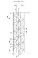
- FIG. 1 is a schematic diagram of a first mixing device according to a first embodiment of the invention
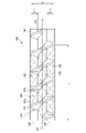
- FIG. FIG. 4 is a schematic view of a second mixing device according to a second embodiment
- Fig. 3 is a schematic view of a third mixing device according to a third embodiment
- FIG. 4 is a schematic diagram of a fourth mixing device according to a fourth embodiment
- FIG. 5 is a schematic view of a fifth mixing device according to a fifth embodiment
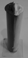
- FIG. 10 is a photograph showing a mixed state in Example 1-1 according to the first mixing device
- FIG. FIG. 10 is a photograph showing a mixed state in Example 1-1 according to the first mixing device
- FIG. FIG. 10 is a photograph showing a mixed state according to Example 1-2 of the first mixing device
- FIG. 10 is a photograph showing a mixed state according to Example 1-2 of the first mixing device;
- FIG. FIG. 10 is a photograph showing a mixed state in Example 2-1 according to the second mixing device;
- FIG. 10 is a photograph showing a mixed state in Example 2-1 according to the second mixing device;
- FIG. 10 is a photograph showing a mixed state according to Example 2-2 of the second mixing device;
- FIG. 10 is a photograph showing a mixed state according to Example 2-2 of the second mixing device;
- FIG. It is a photograph which shows the mixing state by Example 3 based on a 3rd mixing apparatus.
- It is a photograph which shows the mixing state by Example 3 based on a 3rd mixing apparatus.
- 10 is a photograph showing a mixed state according to Comparative Example 3-1.
- FIG. 10 is a photograph showing a mixed state according to Comparative Example 3-1.
- 10 is a photograph showing a mixed state according to Comparative Example 3-2.
- 10 is a photograph showing a mixed state according to Comparative Example 3-2.
- FIG. 11 is a photograph showing a mixed state according to Example 4 of the fourth mixing device;
- FIG. 11 is a photograph showing a mixed state according to Example 4 of the fourth mixing device;
- FIG. 11 is a photograph showing a mixed state according to Example 5 of the fifth mixing device;
- FIG. FIG. 11 is a photograph showing a mixed state according to Example 5 of the fifth mixing device;
- FIG. 10 is a photograph showing a mixed state according to Comparative Example 5.
- FIG. 10 is a photograph showing a mixed state according to Comparative Example 5.
- FIG. 10 is a photograph showing a mixed state according to Comparative Example 5.
- FIG. 11 is a front view of a sixth mixing device according to a sixth embodiment;
- FIG. 11 is a rear view of a sixth mixing device according to a sixth embodiment;
- FIG. 11 is a left side view of a sixth mixing device according to a sixth embodiment;
- FIG. 11 is a right side view of the sixth mixing device according to the sixth embodiment;
- FIG. 11 is a plan view of a sixth mixing device according to a sixth embodiment;
- FIG. 11 is a bottom view of a sixth mixing device according to a sixth embodiment;
- FIG. 29 is a cross-sectional view taken along line AA of FIG. 28;
- FIG. 27 is a cross-sectional view taken along line BB of FIG. 26;
- FIG. 11 is a top right perspective view of a sixth mixing device according to a sixth embodiment;
- FIG. 11 is a bottom left perspective view of a sixth mixing device according to a sixth embodiment;
- a first mixing device 100 according to a first embodiment of the present invention will be described below with reference to FIG.
- the first mixing device 100 mainly includes a first mixing blade 110 and a storage pipe 190, and is made of resin and/or metal. Also, the first mixing blade 110 mainly includes a first shaft 120 , a first blade 140 and a second blade 160 .
- the first shaft 120 is, for example, a cylinder having a diameter of approximately 16.5 mm and an axial length of approximately 150 mm.
- the first vane 140 is a spiral formed continuously around the first axis 120 . More specifically, for example, a band-shaped flat plate having a width of 12 mm is wound five times around the outer circumference of the first shaft 120 so as to draw a spiral clockwise with respect to the traveling direction of the fluid, which will be described later. That is, the flat plate is attached to the outer circumference of the first shaft 120 so that the width direction of the flat plate protrudes from the first shaft 120 along the radial direction of the first shaft 120 .
- the winding start and winding end of the first blade 140 are at the same position around the first shaft 120 .
- the pitch of the first blades 140 with respect to the direction of the first axis 120 is, for example, about 30 mm.
- portions of the blades that face each other in the direction of the first axis 120 are called opposing blade portions 141a and 141b.
- the second blade 160 is twisted around a second axis 180 parallel to the first axis (X) 120 . More specifically, the second blade 160 has a shape obtained by twisting a strip-shaped flat plate having a width of 12 mm, for example, by twisting it 180 degrees around an axis running longitudinally through the widthwise center of the flat plate, that is, half a turn.
- a second blade 160 twisted clockwise with respect to the traveling direction of the fluid described later is referred to as a second right-handed blade 162, and a second blade 160 twisted counterclockwise is referred to as a second left-handed blade. It is called vane 164 .
- the direction in which the blades are twisted is referred to as the blade twisting direction, and when all the second blades 160 are twisted in the same direction, the twisting direction of the second blades 160 is the same direction and is twisted clockwise.
- the twist direction of the second blade 160 is referred to as the left-right direction when it includes both the twisted direction and the counterclockwise twisted direction.
- the second right-handed blade 162 and the second left-handed blade 164 are provided between the opposing blade portions 141a and 141b in the axial direction of the first shaft 120, and are provided in the radial direction of the first shaft 120. , is provided between the outer circumference of the first shaft 120 and the outer end of the first vane 140 .
- the second right-handed blade 162 and the second left-handed blade 164 do not contact the storage tube 190 .
- the width directions of the ends of the second right-handed blades 162 and the second left-handed blades 164 are along the radial direction of the first shaft 120 and alternate with respect to the circumferential direction of the first shaft 120. are mounted on the opposing vane portions 141a, 141b so that.
- a total of 36 second blades 160 are provided, including 18 second right-handed blades 162 and 18 second left-handed blades 164 .
- Attachment of the second vane 160 to the opposing vane portions 141a, 141b is by adhesive, welding, and/or solder, or the like.
- the distance between the second right-handed blade 162 and the second left-handed blade 164 in the circumferential direction of the first shaft 120, that is, about the first shaft 120, is the distance between the second right-handed blade 162 and the second left-handed blade 164. It has a length that is at least 1 time and less than 2 times the diameter of the rotating blade 164 . This spacing in this embodiment is, for example, 10 mm.
- the storage tube 190 has a cylindrical shape having an axial length equal to or longer than the axial length of the first mixing blade 110 and an inner diameter that causes slight friction with the outer circumference of the first mixing blade 110. and accommodates the first mixing blade 110 in its inner periphery.
- the storage tube 190 has an inner diameter D of, for example, 40 mm and a length of, for example, 150 mm.
- the inner periphery of the storage tube 190 is in close contact with the outer periphery of the first mixing blade 110 to the extent that fluid does not flow between the outer periphery of the first vane 140 and the inner periphery of the storage tube 190 .
- the use of the first mixing device 100 will be explained. Two or more fluids are sent from one end of the first mixing device 100, that is, the inflow end. The two or more fluids, while flowing between the first vane 140 and the storage tube 190, alternately impinge on the second right-handed vane 162 and the second left-handed vane 164, are sheared and mixed together. To go. After flowing between the 36 second blades 160, the mixture is sufficiently mixed and flows out from the other end of the first mixing device 100, that is, the outflow end.
- the fluid is preferably, for example, a two-component urethane paint, a three-component urethane paint, or a two-component or three-component waterproof material (hereinafter referred to as paint or the like), but is not limited to these.
- the first mixing device 100 capable of sufficiently mixing a plurality of fluids is obtained.
- the fluids are mixed to the extent that a sufficient coating quality can be obtained.
- FIG. 1 Configurations similar to those of the first embodiment are denoted by the same reference numerals, and descriptions thereof are omitted. Note that the storage tube 190 is omitted in FIG.
- the second mixing device 200 mainly includes a second mixing blade 210 and a storage tube 190, and is made of resin and/or metal. Also, the second mixing blade 210 mainly includes a first shaft 120 , a first blade 140 and a second blade 260 . Since the storage tube 190, the first shaft 120, and the first blades 140 are the same as those in the first embodiment, description thereof is omitted.
- the second blade 260 includes only the second right-handed blade 162 .
- the second right-handed blade 162 is provided between the opposing blade portions 141a and 141b in the axial direction of the first shaft 120, and is located on the outer circumference of the first shaft 120 in the radial direction of the first shaft 120. and the outer edge of the first vane 140 .
- the second blade 260 does not contact the storage tube 190 .
- the second right-handed blade 162 has opposite blade portions 141a and 141b such that the width direction of the end thereof is along the radial direction of the first shaft 120 and alternately with respect to the circumferential direction of the first shaft 120. mounted on top.
- 36 second right-handed blades 162 are provided.
- the interval between the second right-handed blades 162 in the circumferential direction of the first shaft 120, that is, around the first shaft 120, is equal to or more than twice the diameter of the second right-handed blades 162 and less than two times. is.
- This spacing in this embodiment is, for example, 10 mm.
- the second vane 260 is provided along the entire length of the spiral of the first vane 140 , ie along the entire length of the first shaft 120 .
- the use of the second mixing device 200 will be explained. Two or more fluids are sent from one end of the second mixing device 200, that is, the inflow end. As the two or more fluids flow between the first vane 140 and the storage tube 190, they impinge on the second right-handed vane 162, are sheared, and mix together. After flowing between the 36 second right-handed blades 162, the mixture is sufficiently mixed and flows out from the other end of the second mixing device 200, that is, the outflow end.
- FIG. 3 Components similar to those of the first and second embodiments are denoted by the same reference numerals, and descriptions thereof are omitted. Note that the storage tube 190 is omitted in FIG.
- the third mixing device 300 mainly includes a third mixing blade 310 and a storage pipe 190, and is made of resin and/or metal. Also, the third mixing blade 310 mainly includes a first shaft 120 , a first blade 140 and a second blade 360 . Since the storage tube 190, the first shaft 120, and the first blades 140 are the same as those in the first embodiment, description thereof is omitted.
- the second blade 360 includes only the second right-handed blade 162 .
- the second right-handed blades 162 are provided in the same manner as in the second embodiment, but this embodiment differs from the second embodiment in that 24 second right-handed blades 162 are provided.
- the interval between the second right-handed blades 162 in the circumferential direction of the first shaft 120, that is, around the first shaft 120, is equal to or more than twice the diameter of the second right-handed blades 162 and less than two times. is. This spacing in this embodiment is, for example, 10 mm.
- the second right-handed blade 162 is not provided over the entire length of the spiral of the first blade 140, that is, the entire length of the first shaft 120, and the space where the second blade 360 is not provided is the inflow end side.
- the use of the third mixing device 300 will be explained. Two or more fluids are delivered from one end of the third mixing device 300 . As the two or more fluids flow between the first vane 140 and the storage tube 190, they impinge on the second right-handed vane 162, are sheared, and mix together. After flowing through the 24 second right-handed blades 162 , the mixture is sufficiently mixed and flows out from the other end of the third mixing device 300 .
- the length along the spiral of the first blade 140 is explained as being the same as in the first embodiment.
- the length of the second blade 360 provided along the spiral of the first blade 140 is equal to the spiral length of the first blade 140, and a space in which the second blade 360 is not provided is provided on the inflow end side.
- the axial length of the third mixing device 300 may be shorter than that of the first embodiment.
- the fourth mixing device 400 mainly includes a fourth mixing blade 410 and a storage tube 190, and is made of resin and/or metal. Also, the fourth mixing blade 410 mainly includes a first shaft 120 , a first blade 140 and a second blade 460 . Since the storage tube 190, the first shaft 120, and the first blades 140 are the same as those in the first embodiment, description thereof is omitted.
- the second blade 460 includes a second right-handed blade 162 and a second left-handed blade 164 .
- the second right-handed blades 162 and the second left-handed blades 164 are provided in the same manner as in the first embodiment, but in this embodiment, 12 second right-handed blades 162 and 12 It differs from the first embodiment in that a second left-handed blade 164 is provided.
- the second right-handed blades 162 and the second left-handed blades 164 are provided alternately, and the second right-handed blades 162 and the second left-handed blades 162 and 164 are arranged in the circumferential direction of the first shaft 120, that is, around the first shaft 120.
- the interval between the left-handed blades 164 is at least 1 and less than 2 times the diameter of the second right-handed blade 162 and the second left-handed blade 164 .
- This spacing in this embodiment is, for example, 10 mm. That is, the second right-handed blade 162 and the second left-handed blade 164 are not provided over the entire length of the spiral of the first blade 140, that is, the entire length of the first shaft 120, and the second blade 360 is A space that cannot be provided is formed on the inflow end side.
- the use of the fourth mixing device 400 will be explained. Two or more fluids are delivered from one end of the fourth mixing device 400 . As the two or more fluids flow between the first vane 140 and the storage tube 190, they collide with the second right-handed vane 162 and the second left-handed vane 164 and are sheared and mixed together. . After flowing through the 24 second blades 460, the mixture is sufficiently mixed and flows out from the other end of the fourth mixing device 400.
- the length along the spiral of the first blade 140 is explained as being the same as in the first embodiment.
- the length of the second blade 460 provided along the spiral of the first blade 140 is equal to the spiral length of the first blade 140, and a space in which the second blade 460 is not provided is provided on the inflow end side.
- the axial length of the fourth mixing device 400 may be shorter than that of the first embodiment.
- FIG. 1 Configurations similar to those of the first to fourth embodiments are denoted by the same reference numerals, and descriptions thereof are omitted. Note that the storage tube 190 is omitted in FIG.
- the fifth mixing device 500 mainly includes a fifth mixing blade 510 and a storage tube 190, and is made of resin and/or metal. Also, the fifth mixing blade 510 mainly includes a first shaft 120 , a first blade 140 and a second blade 560 . Since the storage tube 190, the first shaft 120, and the first blades 140 are the same as those in the first embodiment, description thereof is omitted.
- the second blade 560 includes a second right-handed blade 162 and a second left-handed blade 164 .
- the second right-handed blade 162 and the second left-handed blade 164 are provided in the same manner as in the first embodiment, but in this embodiment, six second right-handed blades 162 and six It differs from the first embodiment in that a second left-handed blade 164 is provided.
- the second right-handed blades 162 and the second left-handed blades 164 are provided alternately, and the second right-handed blades 162 and the second left-handed blades 162 and 164 are arranged in the circumferential direction of the first shaft 120, that is, around the first shaft 120.
- the interval between the left-handed blades 164 is at least 1 and less than 2 times the diameter of the second right-handed blade 162 and the second left-handed blade 164 .
- This spacing in this embodiment is, for example, 10 mm. That is, the second right-handed blade 162 and the second left-handed blade 164 are not provided over the entire length of the spiral of the first blade 140, that is, the entire length of the first shaft 120, and the second blade 360 is A space that cannot be provided is formed on the inflow end side.
- the use of the fifth mixing device 500 will be explained. Two or more fluids are delivered from one end of the fifth mixing device 500 . As the two or more fluids flow between the first vane 140 and the storage tube 190, they collide with the second right-handed vane 162 and the second left-handed vane 164 and are sheared and mixed together. . After flowing between the twelve second blades 560, the mixture is sufficiently mixed and flows out from the other end of the fifth mixing device 500.
- the length along the spiral of the first blade 140 is explained as being the same as in the first embodiment.
- the length of the second blade 560 provided along the spiral of the first blade 140 is equal to the spiral length of the first blade 140, and a space in which the second blade 560 is not provided is provided on the inflow end side.
- the axial length of the fifth mixing device 500 may be shorter than that of the first embodiment.
- Example 1-1 Using the first mixing device 100, first, two liquids having viscosities of 50,000 cp were filled into the storage tube 190 whose one end opening was closed, in a plane including the axis of the storage tube 190 . Then, the storage pipe 190 was erected with the closed opening as the bottom, and the first mixing blade 110 was inserted from the top opening, which is the other end, so that the spiral direction of the first blade 140 turned to the right.
- Example 1-2 Using the first mixing device 100, first, two liquids having a viscosity of 35,000 cp were filled in the storage tube 190 with one end closed by dividing them by one plane including the axis of the storage tube 190. FIG. Then, the storage pipe 190 was erected with the closed opening as the bottom, and the first mixing blade 110 was inserted from the top opening, which is the other end, so that the spiral direction of the first blade 140 turned to the right.
- Example 2-1 Using the second mixing device 200, first, two liquids having viscosities of 50,000 cp were filled into the storage tube 190 whose one end opening was closed, in a plane including the axis of the storage tube 190 . Then, the storage tube 190 was erected with the closed opening as the bottom, and the second mixing blade 210 was inserted from the top opening, which is the other end, so that the helical direction of the first blade 140 turned to the right.
- Example 2-2 Using the second mixing device 200, first, two liquids having a viscosity of 35,000 cp were filled into the storage tube 190 whose one end opening was closed, separately on one plane including the axis of the storage tube 190. FIG. Then, the storage tube 190 was erected with the closed opening as the bottom, and the second mixing blade 210 was inserted from the top opening, which is the other end, so that the helical direction of the first blade 140 turned to the right.
- Example 3 Using the third mixing device 300 , first, two liquids having a viscosity of 35,000 cp were filled in the storage tube 190 whose one end opening was closed by dividing them by one plane including the axis of the storage tube 190 . Then, the storage pipe 190 was erected with the blocked opening as the bottom, and the third mixing blade 310 was inserted from the top opening, which is the other end, so that the spiral direction of the first blade 140 turned to the right.
- Example 4 Using the fourth mixing device 400 , first, two liquids having a viscosity of 8,000 cp were filled into the storage tube 190 whose one end opening was closed, separately on one plane including the axis of the storage tube 190 . Then, the storage tube 190 was erected with the closed opening as the bottom, and the fourth mixing blade 410 was inserted from the top opening, which is the other end, so that the spiral direction of the first blade 140 turned to the right.
- Example 5 Using the fifth mixing device 500 , first, two liquids having a viscosity of 8,000 cp were filled in the storage tube 190 with one end closed by dividing them by one plane including the axis of the storage tube 190 . Then, the storage tube 190 was erected with the closed opening as the bottom, and the fifth mixing blade 510 was inserted from the top opening, which is the other end, so that the helical direction of the first blade 140 turned to the right.
- Table 1 is a table listing the experimental results.
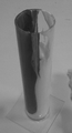
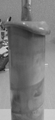
- Example 1-1 The experimental conditions of Example 1-1 are shown in FIGS.
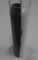
- FIG. 6 shows storage tube 190 filled with two liquids having viscosities of 50,000 cp. The two fluids were given different colors to visualize the mixing state.
- FIG. 7 shows a state in which all the first mixing blades 110 are inserted into the storage tube 190 . It was found that the two liquids inside the storage tube 190 were thoroughly mixed at the top.
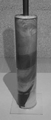
- Example 1-2 The experimental conditions of Example 1-2 are shown in FIGS.
- FIG. 8 shows storage tube 190 filled with two liquids having viscosities of 35,000 cp. The two fluids were given different colors to visualize the mixing state.
- FIG. 9 shows a state in which all the first mixing blades 110 are inserted into the storage tube 190 . It was found that the two liquids inside the storage tube 190 were thoroughly mixed at the top.
- Example 2-1 The experimental conditions of Example 2-1 are shown in FIGS. 10 and 11.
- FIG. 10 shows storage tube 190 filled with two liquids having viscosities of 50,000 cp. The two fluids were given different colors to visualize the mixing state.
- FIG. 11 shows a state in which the second mixing blades 210 are completely inserted into the storage tube 190 . It was found that the two liquids inside the storage tube 190 were thoroughly mixed at the top.
- Example 2-2 The experimental conditions of Example 2-2 are shown in FIGS. 12 and 13.
- FIG. 12 shows storage tube 190 filled with two liquids having viscosities of 35,000 cp. The two fluids were given different colors to visualize the mixing state.
- FIG. 13 shows a state in which the second mixing blades 210 are completely inserted into the storage tube 190 . It was found that the two liquids inside the storage tube 190 were thoroughly mixed at the top.
- Example 3 The experimental situation of Example 3 is shown in FIGS. 14 and 15.
- FIG. 14 shows storage tube 190 filled with two liquids having viscosities of 35,000 cp. The two fluids were given different colors to visualize the mixing state.
- FIG. 15 shows a state in which the third mixing blades 310 are completely inserted into the storage tube 190. FIG. It was found that the two liquids inside the storage tube 190 were thoroughly mixed at the top.
- FIG. 16 and 17 show the experimental conditions of Comparative Example 3-1.
- FIG. 16 shows storage tube 190 filled with two liquids having viscosities of 35,000 cp. The two fluids were given different colors to visualize the mixing state.
- FIG. 17 shows a state in which the entire length of the mixing impeller, which has twelve second clockwise impellers 162 and twelve second counterclockwise impellers 164 at intervals of 1 cm, is inserted into the storage tube 190 .
- the two liquids inside the storage tube 190 were found to be slightly immiscible at the top.
- FIG. 18 and 19 show the experimental conditions of Comparative Example 3-2.
- FIG. 18 shows storage tube 190 filled with two liquids having viscosities of 35,000 cp. The two fluids were given different colors to visualize the mixing state.
- FIG. 19 shows a state in which the entire length of the mixing blade, which has 12 second right-handed blades 162 and 12 second left-handed blades 164 provided at intervals of 2 cm, is inserted into the storage tube 190 .
- the two liquids inside the storage tube 190 were found to be slightly immiscible at the top.
- Example 4 The experimental conditions of Example 4 are shown in FIGS. 20 and 21.
- FIG. FIG. 20 shows storage tube 190 filled with two liquids having viscosities of 8,000 cp. The two fluids were given different colors to visualize the mixing state.
- FIG. 21 shows a state in which the fourth mixing blade 410 is completely inserted into the storage tube 190. FIG. It was found that the two liquids inside the storage tube 190 were thoroughly mixed at the top.
- the viscosity of the two blades is 35,000 or less. While the fluids are sufficiently mixed, when the blade twist direction is the horizontal direction, the two fluids with a viscosity of 35,000 are slightly mixed, but when the viscosity is 8,000, they are completely mixed. rice field. Further, it was found that two fluids with a viscosity of 35,000 are not completely mixed when the blade interval is 2 cm.
- Example 5 The experimental conditions of Example 5 are shown in FIGS.
- FIG. 22 shows storage tube 190 filled with two liquids having viscosities of 8,000 cp. The two fluids were given different colors to visualize the mixing state.
- FIG. 23 shows a state in which the fifth mixing blade 510 is completely inserted into the storage tube 190. FIG. It was found that the two liquids inside the storage tube 190 were thoroughly mixed at the top.
- Comparative Example 5 The experimental conditions of Comparative Example 5 are shown in FIGS.
- FIG. 24 shows storage tube 190 filled with two liquids having viscosities of 35,000 cp. The two fluids were given different colors to visualize the mixing state.
- FIG. 25 shows a state in which the fifth mixing blade 510 is completely inserted into the storage tube 190.
- FIG. The two liquids inside the storage tube 190 were found to be slightly immiscible at the top.
- Example 5 when there are a total of 12 second blades 560, the blade twist direction is the left-right direction, and the blade interval is 1 cm, two fluids with a viscosity of 8,000 or less are sufficiently mixed. , two fluids with a viscosity of 35,000 are slightly immiscible.
- the ratio L/D is preferably 1 or more and 4 or less, 1.25 or more and 3.75 or less, 2 or more and 4 or less, more preferably 2.50 or more and 3.75 or less
- the effective ratio L/D' is , preferably 2 or more and 7 or less, 2.13 or more and 6.38 or less, 4 or more and 7 or less, more preferably 4.26 or more and 6.38 or less.
- FIGS. 26-35 Configurations similar to those of the first to fifth embodiments are denoted by the same reference numerals, and descriptions thereof are omitted.
- 26 to 35 the storage tube 190 is omitted.
- the sixth mixing device 600 mainly includes a sixth mixing blade 610 and a storage tube 190, and is made of resin and/or metal. Also, the sixth mixing blade 610 mainly includes a sixth shaft 620 , a sixth large blade 640 and a sixth small blade 660 . The size of the sixth mixing device 600 is smaller than the mixing devices according to the first to fifth embodiments. In addition, the sixth large blade 640 is not biased toward one end of both ends of the sixth mixing device 600, but is provided in the center of the sixth mixing device 600 in the axial direction, and evenly spreads over both ends. Spaced out.
- the sixth mixing device 600 mainly includes a sixth mixing blade 610 and a storage tube 190, and is made of resin and/or metal.
- the sixth mixing blade 610 has an axial length of about 80 mm and a diameter of about 20.8 mm. Also, the sixth mixing blade 610 mainly includes one sixth shaft 620 , one sixth large blade 640 and twenty-four sixth small blades 660 .
- the sixth shaft 620 is, for example, a cylinder having a diameter of approximately 8.5 mm and an axial length of approximately 80 mm. At both ends of the sixth shaft 620, through holes 675 and 685 having a J-shaped axial cross-section are formed extending from the end surface to the outer peripheral surface (see FIGS. 32 and 33). In the sixth shaft 620, the circular holes of the through holes 675 and 685 opening on the side face are shifted about 120 degrees from the axial direction.
- the sixth large blade 640 is a spiral formed continuously around the sixth shaft 620 with a slight distance, for example, about 5 mm, in the axial direction from both ends of the sixth shaft 620 . More specifically, for example, a strip-shaped plate having a width of about 4 mm and a thickness of about 2 mm is arranged around the outer periphery of the sixth shaft 620 by about 4 mm so as to draw a spiral clockwise in the direction of movement of the fluid, which will be described later. and 1/3 turn. In other words, the flat plate is attached to the outer periphery of sixth shaft 620 so that the width direction of the plate protrudes from sixth shaft 620 along the radial direction of sixth shaft 620 .
- the winding start and the winding end of the sixth large blade 640 are at positions shifted by about 120 degrees around the axis of the sixth shaft 120 .
- the pitch of the sixth large blades 640 with respect to the direction of the sixth axis 620 is, for example, approximately 16 mm.
- portions of blades that face each other in the direction of the sixth axis 620 are referred to as opposing blade portions 641a and 641b.
- the spacing between the opposing vane portions 641a, 641b is approximately 14 mm.
- An outflow sidewall 670 is formed between the sixth large blade 640 and the sixth shaft 620 at the outflow end shown on the upper side in FIG. 26, and the inflow side end shown on the lower side in FIG.
- an inflow sidewall 680 is formed between the sixth large blade 640 and the sixth shaft 620 .
- the outflow side wall 670 has a cylindrical shape wound so as to form the outer circumference of the sixth mixing blade 610, and extends approximately 360 degrees along the sixth large blade 640 from the opposing blade portion 641a to the outflow side. It has walls extending to the ends.
- a space is formed between the outflow sidewall 670 , the sixth large blade 640 and the sixth shaft 620 .
- a through hole 675 extends from the inner surface of the sixth shaft 620 into this space.
- the inflow side wall 680 has a cylindrical shape wound around the outer periphery of the sixth mixing blade 610, and extends approximately 360 degrees along the sixth large blade 640 from the opposing blade portion 641a to the inflow side. It has walls extending to the ends.
- a space is formed between the outflow sidewall 670 , the sixth large blade 640 and the sixth shaft 620 .
- a through hole 685 extends from the inner surface of the sixth shaft 620 into this space.
- the sixth small blade 660 is twisted clockwise around the second axis Y parallel to the first axis X toward the traveling direction of the fluid, which will be described later. More specifically, the sixth small blade 660 is formed by turning a strip-shaped flat plate, for example, about 5.5 mm wide and about 0.8 mm thick, about an axis running longitudinally through the widthwise center of the flat plate 180 degrees, that is, It has a shape that is twisted clockwise toward the direction of movement of the fluid, half a turn. All sixth leaflets 660 are twisted in the same direction. Three or four sixth bladelets 660 are coaxially arranged in the second axis Y direction.
- the sixth small blade 660 is provided between the opposed blade portions 641a and 641b in the axial direction of the sixth shaft 620, and is located between the outer circumference of the sixth shaft 620 and the radial direction of the sixth shaft 620. It is provided between the outer ends of the sixth large blades 640 .
- both ends of the sixth small blade 660 are in contact with the storage tube 190 or slightly in contact with the storage tube 190 , but may not be in contact with each other.
- the sixth bladelets 660 are mounted on the opposing blade portions 641 a , 641 b such that the width direction of their ends is along the radial direction of the sixth axis 620 .
- Attachment of the sixth small blade 660 and the opposing blade portions 641a, 641b may be by adhesive, welding, and/or solder, etc., and the sixth mixing blade 610 may be integrally molded, such as by a 3D printer.
- the interval between the sixth small blades 660 in the circumferential direction of the sixth axis 620, that is, around the sixth axis 620, is 0 times or more and less than 2 times the diameter of the sixth small blades 660. . That is, the sixth bladelets 660 may contact each other or may be spaced apart. This spacing in this embodiment is, for example, about 1 mm.
- a sixth minor blade 660 is provided along the entire length of the spiral of the sixth large blade 640 , ie, along the entire length of the sixth shaft 620 .
- the storage tube 190 has an axial length equal to or longer than the axial length of the sixth mixing blade 610, and has a cylindrical shape with an inner diameter that causes slight friction with the outer circumference of the sixth mixing blade 610. and the sixth mixing blade 610 is accommodated in the inner periphery thereof.
- the inner diameter D of the storage tube 190 is, for example, about 21 mm, and the length is, for example, about 80 mm or more.
- the inner periphery of the storage tube 190 is in close contact with the outer periphery of the sixth mixing blade 610 to the extent that fluid does not flow between the outer periphery of the sixth large blade 640 and the inner periphery of the storage tube 190 .
- the use of the sixth mixing device 600 will be explained. Two or more fluids are delivered from one inlet end of the sixth mixing device 600 . The two or more fluids pass through the interior of the through hole 685 and then flow between the inlet sidewall 680 and the sixth axis 620 or directly between the inlet sidewall 680 and the sixth axis 620 . It flows in and reaches the sixth large blade 640 . Then, while flowing between the sixth large blade 640 and the storage tube 190, it collides with the sixth small blade 660, is sheared by the adjacent sixth small blade 660, and is mixed with each other. Then, after flowing between the 24 sixth small blades 660 , it reaches the outflow side wall 670 . After that, the fluid passes between the outflow side wall 670 and the sixth shaft 620 or passes through the inside of the through hole 675 and is sufficiently mixed from the outflow end, which is the other end of the sixth mixing device 600. be drained.
- the sixth mixing device 600 is smaller and lighter than the first to fifth embodiments, workers can mix two or more fluids while holding it by hand for a long time.
- the mixed fluid is pumped to the construction site. It was pumped, flowed from a hose or the like to the construction surface, and then leveled on the construction surface using a rake or the like.
- the second blade does not contact the storage tube 190 when the first mixing blade 110 is inserted into the storage tube 190. may come into contact with
- the second blades may be omitted for ease of explanation, and may not always match the numbers described in the embodiments described herein.
- each member shown in this specification and drawings are examples, and are not limited to these.
- the material of each member is an example, and is not limited to these.
- first mixing device 110 first mixing blade 120 first shaft 140 first blade 141a opposing blade portion 141b opposing blade portion 160 second blade 162 second right-handed blade 164 second left-handed blade 180 Second shaft 190 Storage tube 200 Second mixing device 210 Second mixing blade 300 Third mixing device 310 Third mixing blade 400 Fourth mixing device 410 Fourth mixing blade 500 Fifth mixing device 510 5th mixing blade 600 6th mixing device 610 6th mixing blade
Abstract
[Problem] To obtain a mixing blade and a mixing device capable of mixing a plurality of liquids sufficiently. [Solution] A first mixing device 100 mainly comprises a first mixing blade 110 and a housing pipe 190, and is made of resin and/or metal. In addition, the first mixing blade 110 mainly comprises a first shaft 120, a first blade 140, and a second blade 160. The first shaft 120 is a cylinder. The first blade 140 is a spiral continuously formed around the first shaft 120. The second blade 160 is formed by being twisted around a second shaft 180 parallel to the first shaft 120. The housing pipe 190 has a cylindrical shape having an axial length longer than or equal to the axial length of the first mixing blade 110 and having an inner diameter that causes slight friction against an outer circumference of the first mixing blade 110. An inner circumference of the housing pipe 190 is in close contact with the outer circumference of the first mixing blade 110 to an extent that prevents fluid from flowing in between an outer circumference of the first blade 140 and the inner circumference of the housing pipe 190.
Description
本発明は、液体を混合する混合羽根及び混合装置に関する。
The present invention relates to a mixing blade and mixing device for mixing liquids.
第1の螺旋状帯板21と第2の螺旋状帯板22とを備える攪拌エレメント2が知られている。第1の螺旋状帯板21の外縁部は、第2の螺旋状帯板22の内縁部と、互いに食い込まされた状態で固着される。第1の螺旋状帯板21は、流体をハウジング1の略全長において軸心回りの一方向へ螺旋状に旋回させ、第2の螺旋状帯板22は、該螺旋状帯板の外周側に巻回した状態に設けられ、上記流体をハウジングの略全長において軸心回りの他方向へ螺旋状に旋回させる(特許文献1)。
A stirring element 2 comprising a first spiral strip 21 and a second spiral strip 22 is known. The outer edge of the first spiral strip 21 is fixed to the inner edge of the second spiral strip 22 in a state of being bitten into each other. The first spiral band plate 21 causes the fluid to spirally swirl in one direction around the axis over substantially the entire length of the housing 1, and the second spiral band plate 22 is arranged on the outer peripheral side of the spiral band plate. It is provided in a wound state, and spirally turns the fluid in the other direction around the axis over substantially the entire length of the housing (Patent Document 1).
しかし、従来の構成では、複数の流体を十分に混合できない場合がある。
However, the conventional configuration may not be able to sufficiently mix multiple fluids.
本発明は、上記課題に鑑みてなされたものであり、複数の液体を十分に混合可能な混合羽根及び混合装置を得ることを目的とする。
The present invention has been made in view of the above problems, and an object of the present invention is to obtain a mixing blade and a mixing device capable of sufficiently mixing a plurality of liquids.
本願第1の発明による混合羽根は、第1の軸の回りに螺旋状を成す第1の羽根と、第1の軸と平行である第2の軸の回りに捻られる第2の羽根とを備え、第2の羽根は、第1の羽根において第1の軸方向において向かい合う対向羽根部分の間に設けられることを特徴とする。
The mixing blade according to the first invention of the present application includes a first blade spiraling around a first axis and a second blade twisted around a second axis parallel to the first axis. The second blade is provided between opposing blade portions of the first blade that face each other in the first axial direction.
第1の軸は円柱形状であって、第2の羽根は、第1の軸と、第1の羽根の外側端との間に設けられることが好ましい。
It is preferable that the first shaft is cylindrical and the second blades are provided between the first shaft and the outer ends of the first blades.
複数の第2の羽根が設けられ、第1の軸回りに対する第2の羽根どうしの間隔は、第2の羽根の直径の1倍以上かつ2倍未満の長さであることが好ましい。
A plurality of second blades are provided, and the interval between the second blades around the first axis is preferably one time or more and less than two times the diameter of the second blades.
第1の羽根は、第1の軸回りに少なくとも5/3回転以上巻回されることが好ましい。
The first blade is preferably wound around the first axis by at least 5/3 turns.
第2の羽根は、第2の軸回りに半回転捻られることが好ましい。
The second blade is preferably twisted half a turn around the second axis.
第2の羽根が捻られる方向は全て同じであることが好ましい。
It is preferable that all the directions in which the second blades are twisted are the same.
第2の羽根は複数であって、第2の羽根が捻られる方向は、第2の軸に対して時計回り又は反時計回りであることが好ましい。
It is preferable that there are a plurality of second blades and the direction in which the second blades are twisted is clockwise or counterclockwise with respect to the second axis.
本願第2の発明による混合装置は、前記混合羽根と、混合羽根を収納する収納管とを備えることを特徴とする。
The mixing device according to the second invention of the present application is characterized by comprising the mixing blade and a storage pipe for housing the mixing blade.
収納管の内径から第1の軸の直径を除いた実効内径D’に対する、第1の軸方向において第2の羽根が設けられる部分の長さである第2の羽根長さLの比L/D’は、好ましくは2以上7以下、より好ましくは4以上7以下であることが好ましい。
Ratio L/ D' is preferably 2 or more and 7 or less, more preferably 4 or more and 7 or less.
本発明によれば、複数の液体を十分に混合可能な混合羽根及び混合装置を得る。
According to the present invention, a mixing blade and a mixing device capable of sufficiently mixing a plurality of liquids are obtained.
以下、図1を参照して、本発明の第1の実施形態による第1の混合装置100について説明する。
A first mixing device 100 according to a first embodiment of the present invention will be described below with reference to FIG.
第1の混合装置100は、第1の混合羽根110と、収納管190とを主に備え、樹脂及び/又は金属から成る。また、第1の混合羽根110は、第1の軸120と、第1の羽根140と、第2の羽根160とを主に備える。
The first mixing device 100 mainly includes a first mixing blade 110 and a storage pipe 190, and is made of resin and/or metal. Also, the first mixing blade 110 mainly includes a first shaft 120 , a first blade 140 and a second blade 160 .
第1の軸120は、例えば約16.5mmの直径と約150mmの軸方向長さを有する円柱である。第1の羽根140は、第1の軸120回りに連続的に形成された螺旋である。より詳細には、例えば幅12mmである帯状の平板を、後述される流体の進行方向に対して時計回りに螺旋を描くように、第1の軸120の外周に5周回巻き付けて成る。すなわち平板は、その幅方向が第1の軸120の径方向に沿って第1の軸120から突出するように第1の軸120の外周に取り付けられる。第1の羽根140の巻き始めと巻き終わりは、第1の軸120の軸回りにおいて同じ位置にある。また、第1の軸120方向に対する第1の羽根140のピッチは、例えば約30mmである。第1の羽根140において、第1の軸120方向に対して向かい合う羽根の一部を対向羽根部分141a、141bという。
The first shaft 120 is, for example, a cylinder having a diameter of approximately 16.5 mm and an axial length of approximately 150 mm. The first vane 140 is a spiral formed continuously around the first axis 120 . More specifically, for example, a band-shaped flat plate having a width of 12 mm is wound five times around the outer circumference of the first shaft 120 so as to draw a spiral clockwise with respect to the traveling direction of the fluid, which will be described later. That is, the flat plate is attached to the outer circumference of the first shaft 120 so that the width direction of the flat plate protrudes from the first shaft 120 along the radial direction of the first shaft 120 . The winding start and winding end of the first blade 140 are at the same position around the first shaft 120 . Also, the pitch of the first blades 140 with respect to the direction of the first axis 120 is, for example, about 30 mm. In the first blade 140, portions of the blades that face each other in the direction of the first axis 120 are called opposing blade portions 141a and 141b.
第2の羽根160は、第1の軸(X)120と平行である第2の軸180回りに捻られて成る。より詳細には、第2の羽根160は、例えば幅12mmである帯状の平板を、平板の幅方向中央を長手方向に走る軸回りに180度、つまり半回転、捻って成る形状を有する。後述される流体の進行方向に対して時計回りに捻られた第2の羽根160を第2の右回り羽根162といい、反時計回りに捻られた第2の羽根160を第2の左回り羽根164という。以下、羽根が捻られる方向を羽根捻り方向といい、第2の羽根160が全て同じ方向に捻られている場合を、第2の羽根160の捻り方向が同方向、時計回りに捻られたものと反時計回りに捻られたものとを含む場合を、第2の羽根160の捻り方向が左右方向という。第2の右回り羽根162及び第2の左回り羽根164は、第1の軸120の軸方向においては、対向羽根部分141a、141bの間に設けられ、第1の軸120の径方向においては、第1の軸120の外周と第1の羽根140の外側端との間に設けられる。第1の混合羽根110が収納管190に挿入された状態において、第2の右回り羽根162及び第2の左回り羽根164は、収納管190に接触しない。第2の右回り羽根162及び第2の左回り羽根164は、それらの端部の幅方向が第1の軸120の径方向に沿い、第1の軸120の周方向に対して交互となるように、対向羽根部分141a、141b上に取り付けられる。本実施形態においては、第2の右回り羽根162が18枚、第2の左回り羽根164が18枚、合計36枚の第2の羽根160が設けられる。第2の羽根160と対向羽根部分141a、141bとの取り付けは、接着剤、溶接、及び/又はハンダ等による。第1の軸120の周方向、つまり第1の軸120回りに対する、第2の右回り羽根162と第2の左回り羽根164との間隔は、第2の右回り羽根162と第2の左回り羽根164の直径の1倍以上かつ2倍未満の長さである。本実施形態におけるこの間隔は、例えば10mmである。第2の羽根160は、第1の羽根140の螺旋の全長に沿って、すなわち第1の軸120の全長に渡って設けられる。第1の軸120の長手方向(第1の軸方向)において、第2の羽根160が設けられる部分の長さを第2の羽根長さLとすると、本実施形態では、第2の羽根長さL=150mmである。
The second blade 160 is twisted around a second axis 180 parallel to the first axis (X) 120 . More specifically, the second blade 160 has a shape obtained by twisting a strip-shaped flat plate having a width of 12 mm, for example, by twisting it 180 degrees around an axis running longitudinally through the widthwise center of the flat plate, that is, half a turn. A second blade 160 twisted clockwise with respect to the traveling direction of the fluid described later is referred to as a second right-handed blade 162, and a second blade 160 twisted counterclockwise is referred to as a second left-handed blade. It is called vane 164 . Hereinafter, the direction in which the blades are twisted is referred to as the blade twisting direction, and when all the second blades 160 are twisted in the same direction, the twisting direction of the second blades 160 is the same direction and is twisted clockwise. The twist direction of the second blade 160 is referred to as the left-right direction when it includes both the twisted direction and the counterclockwise twisted direction. The second right-handed blade 162 and the second left-handed blade 164 are provided between the opposing blade portions 141a and 141b in the axial direction of the first shaft 120, and are provided in the radial direction of the first shaft 120. , is provided between the outer circumference of the first shaft 120 and the outer end of the first vane 140 . When the first mixing blade 110 is inserted into the storage tube 190 , the second right-handed blade 162 and the second left-handed blade 164 do not contact the storage tube 190 . The width directions of the ends of the second right-handed blades 162 and the second left-handed blades 164 are along the radial direction of the first shaft 120 and alternate with respect to the circumferential direction of the first shaft 120. are mounted on the opposing vane portions 141a, 141b so that. In this embodiment, a total of 36 second blades 160 are provided, including 18 second right-handed blades 162 and 18 second left-handed blades 164 . Attachment of the second vane 160 to the opposing vane portions 141a, 141b is by adhesive, welding, and/or solder, or the like. The distance between the second right-handed blade 162 and the second left-handed blade 164 in the circumferential direction of the first shaft 120, that is, about the first shaft 120, is the distance between the second right-handed blade 162 and the second left-handed blade 164. It has a length that is at least 1 time and less than 2 times the diameter of the rotating blade 164 . This spacing in this embodiment is, for example, 10 mm. The second vane 160 is provided along the entire length of the spiral of the first vane 140 , ie along the entire length of the first shaft 120 . Assuming that the length of the portion where the second blade 160 is provided in the longitudinal direction (first axial direction) of the first shaft 120 is the second blade length L, in the present embodiment, the second blade length Length L=150 mm.
収納管190は、第1の混合羽根110の軸方向長さ以上の軸方向長さを有し、かつ第1の混合羽根110の外周と若干の摩擦を生じる程度の内径を有する円筒形状であって、その内周に第1の混合羽根110を収納する。収納管190の内径Dは、例えば40mm、長さは、例えば150mmである。収納管190の内周は、第1の羽根140の外周と収納管190の内周との間に流体が流入しない程度に、第1の混合羽根110の外周と密着する。収納管190の内径Dに対する第2の羽根長さLの比L/Dは、L/D=150/40=3.75である。また、第1の軸120を除いた実効内径D’はD’=40-16.5=23.5mmであるから、実効比L/D’=150/23.5=6.38である。
The storage tube 190 has a cylindrical shape having an axial length equal to or longer than the axial length of the first mixing blade 110 and an inner diameter that causes slight friction with the outer circumference of the first mixing blade 110. and accommodates the first mixing blade 110 in its inner periphery. The storage tube 190 has an inner diameter D of, for example, 40 mm and a length of, for example, 150 mm. The inner periphery of the storage tube 190 is in close contact with the outer periphery of the first mixing blade 110 to the extent that fluid does not flow between the outer periphery of the first vane 140 and the inner periphery of the storage tube 190 . A ratio L/D of the second blade length L to the inner diameter D of the storage tube 190 is L/D=150/40=3.75. Also, since the effective inner diameter D' excluding the first shaft 120 is D'=40-16.5=23.5 mm, the effective ratio L/D'=150/23.5=6.38.
第1の混合装置100の使用について説明する。第1の混合装置100の一端である流入端から、2つ以上の流体が送られる。2つ以上の流体は、第1の羽根140と収納管190との間を流れながら、第2の右回り羽根162及び第2の左回り羽根164に交互に衝突し、せん断され、互いに混合されていく。そして、36枚の第2の羽根160の間を流れた後、第1の混合装置100の他端である流出端から十分に混合されて流出する。
The use of the first mixing device 100 will be explained. Two or more fluids are sent from one end of the first mixing device 100, that is, the inflow end. The two or more fluids, while flowing between the first vane 140 and the storage tube 190, alternately impinge on the second right-handed vane 162 and the second left-handed vane 164, are sheared and mixed together. To go. After flowing between the 36 second blades 160, the mixture is sufficiently mixed and flows out from the other end of the first mixing device 100, that is, the outflow end.
流体は、例えば二液式ウレタン塗料、三液式ウレタン塗料、あるいは二液式又は三液式の防水材(以下、塗料等という)などが好適であるが、これらに限定されない。
The fluid is preferably, for example, a two-component urethane paint, a three-component urethane paint, or a two-component or three-component waterproof material (hereinafter referred to as paint or the like), but is not limited to these.
本実施形態によれば、複数の流体を十分に混合可能な第1の混合装置100を得る。例えば塗料等を第1の混合装置100で混合した場合、十分な塗装品質を得られる程度に流体が混合される。
According to this embodiment, the first mixing device 100 capable of sufficiently mixing a plurality of fluids is obtained. For example, when paint or the like is mixed by the first mixing device 100, the fluids are mixed to the extent that a sufficient coating quality can be obtained.
次に、図2を用いて第2の実施形態による第2の混合装置200について説明する。第1の実施形態と同様の構成については、同じ符号を付して説明を省略する。なお、図2において、収納管190は省略される。
Next, a second mixing device 200 according to the second embodiment will be described using FIG. Configurations similar to those of the first embodiment are denoted by the same reference numerals, and descriptions thereof are omitted. Note that the storage tube 190 is omitted in FIG.
第2の混合装置200は、第2の混合羽根210と、収納管190とを主に備え、樹脂及び/又は金属から成る。また、第2の混合羽根210は、第1の軸120と、第1の羽根140と、第2の羽根260とを主に備える。収納管190、第1の軸120、及び第1の羽根140は、第1の実施形態と同様であるため、説明を省略する。
The second mixing device 200 mainly includes a second mixing blade 210 and a storage tube 190, and is made of resin and/or metal. Also, the second mixing blade 210 mainly includes a first shaft 120 , a first blade 140 and a second blade 260 . Since the storage tube 190, the first shaft 120, and the first blades 140 are the same as those in the first embodiment, description thereof is omitted.
本実施形態による第2の羽根260は、第2の右回り羽根162のみを備える。第2の右回り羽根162は、第1の軸120の軸方向においては、対向羽根部分141a、141bの間に設けられ、第1の軸120の径方向においては、第1の軸120の外周と第1の羽根140の外側端との間に設けられる。第1の混合羽根110が収納管190に挿入された状態において、第2の羽根260は収納管190に接触しない。第2の右回り羽根162は、その端部の幅方向が第1の軸120の径方向に沿い、第1の軸120の周方向に対して交互となるように、対向羽根部分141a、141b上に取り付けられる。本実施形態においては、36枚の第2の右回り羽根162が設けられる。第1の軸120の周方向、つまり第1の軸120回りに対する、第2の右回り羽根162どうしの間隔は、第2の右回り羽根162の直径の1倍以上かつ2倍未満の長さである。本実施形態におけるこの間隔は、例えば10mmである。第2の羽根260は、第1の羽根140の螺旋の全長に沿って、すなわち第1の軸120の全長に渡って設けられる。第1の実施形態と同様、収納管190の内径Dに対する第2の羽根長さLの比L/Dは、L/D=3.75であり、実効比L/D’=6.38である。
The second blade 260 according to this embodiment includes only the second right-handed blade 162 . The second right-handed blade 162 is provided between the opposing blade portions 141a and 141b in the axial direction of the first shaft 120, and is located on the outer circumference of the first shaft 120 in the radial direction of the first shaft 120. and the outer edge of the first vane 140 . When the first mixing blade 110 is inserted into the storage tube 190 , the second blade 260 does not contact the storage tube 190 . The second right-handed blade 162 has opposite blade portions 141a and 141b such that the width direction of the end thereof is along the radial direction of the first shaft 120 and alternately with respect to the circumferential direction of the first shaft 120. mounted on top. In this embodiment, 36 second right-handed blades 162 are provided. The interval between the second right-handed blades 162 in the circumferential direction of the first shaft 120, that is, around the first shaft 120, is equal to or more than twice the diameter of the second right-handed blades 162 and less than two times. is. This spacing in this embodiment is, for example, 10 mm. The second vane 260 is provided along the entire length of the spiral of the first vane 140 , ie along the entire length of the first shaft 120 . As in the first embodiment, the ratio L/D of the second blade length L to the inner diameter D of the storage tube 190 is L/D=3.75, and the effective ratio L/D'=6.38. be.
第2の混合装置200の使用について説明する。第2の混合装置200の一端である流入端から、2つ以上の流体が送られる。2つ以上の流体は、第1の羽根140と収納管190との間を流れながら、第2の右回り羽根162に衝突し、せん断され、互いに混合されていく。そして、36枚の第2の右回り羽根162の間を流れた後、第2の混合装置200の他端である流出端から十分に混合されて流出する。
The use of the second mixing device 200 will be explained. Two or more fluids are sent from one end of the second mixing device 200, that is, the inflow end. As the two or more fluids flow between the first vane 140 and the storage tube 190, they impinge on the second right-handed vane 162, are sheared, and mix together. After flowing between the 36 second right-handed blades 162, the mixture is sufficiently mixed and flows out from the other end of the second mixing device 200, that is, the outflow end.
本実施形態によれば、第1の実施形態と同様の効果を得る。
According to this embodiment, effects similar to those of the first embodiment are obtained.
次に、図3を用いて第3の実施形態による第3の混合装置300について説明する。第1及び第2の実施形態と同様の構成については、同じ符号を付して説明を省略する。なお、図3において、収納管190は省略される。
Next, a third mixing device 300 according to the third embodiment will be described using FIG. Components similar to those of the first and second embodiments are denoted by the same reference numerals, and descriptions thereof are omitted. Note that the storage tube 190 is omitted in FIG.
第3の混合装置300は、第3の混合羽根310と、収納管190とを主に備え、樹脂及び/又は金属から成る。また、第3の混合羽根310は、第1の軸120と、第1の羽根140と、第2の羽根360とを主に備える。収納管190、第1の軸120、及び第1の羽根140は、第1の実施形態と同様であるため、説明を省略する。
The third mixing device 300 mainly includes a third mixing blade 310 and a storage pipe 190, and is made of resin and/or metal. Also, the third mixing blade 310 mainly includes a first shaft 120 , a first blade 140 and a second blade 360 . Since the storage tube 190, the first shaft 120, and the first blades 140 are the same as those in the first embodiment, description thereof is omitted.
本実施形態による第2の羽根360は、第2の右回り羽根162のみを備える。第2の右回り羽根162は、第2の実施形態と同様にして設けられるが、本実施形態においては、24枚の第2の右回り羽根162が設けられる点が第2の実施形態と異なる。第1の軸120の周方向、つまり第1の軸120回りに対する、第2の右回り羽根162どうしの間隔は、第2の右回り羽根162の直径の1倍以上かつ2倍未満の長さである。本実施形態におけるこの間隔は、例えば10mmである。つまり、第2の右回り羽根162は、第1の羽根140の螺旋の全長、すなわち第1の軸120の全長に渡って設けられず、第2の羽根360が設けられない空間が流入端側にできることになる。第1の軸120の長手方向において第2の羽根360が設けられる部分の長さ(第2の羽根長さ)Lは、本実施形態では、第2の羽根長さL=100mmである。よって、収納管190の内径Dに対する第2の羽根長さLの比L/Dは、L/D=100/40=2.50である。また、実効比L/D’=100/23.5=4.26である。
The second blade 360 according to this embodiment includes only the second right-handed blade 162 . The second right-handed blades 162 are provided in the same manner as in the second embodiment, but this embodiment differs from the second embodiment in that 24 second right-handed blades 162 are provided. . The interval between the second right-handed blades 162 in the circumferential direction of the first shaft 120, that is, around the first shaft 120, is equal to or more than twice the diameter of the second right-handed blades 162 and less than two times. is. This spacing in this embodiment is, for example, 10 mm. That is, the second right-handed blade 162 is not provided over the entire length of the spiral of the first blade 140, that is, the entire length of the first shaft 120, and the space where the second blade 360 is not provided is the inflow end side. will be able to The length (second blade length) L of the portion where the second blade 360 is provided in the longitudinal direction of the first shaft 120 is the second blade length L=100 mm in this embodiment. Therefore, the ratio L/D of the second blade length L to the inner diameter D of the storage tube 190 is L/D=100/40=2.50. Also, the effective ratio L/D'=100/23.5=4.26.
第3の混合装置300の使用について説明する。第3の混合装置300の一端から、2つ以上の流体が送られる。2つ以上の流体は、第1の羽根140と収納管190との間を流れながら、第2の右回り羽根162に衝突し、せん断され、互いに混合されていく。そして、24枚の第2の右回り羽根162の間を流れた後、第3の混合装置300の他端から十分に混合されて流出する。
The use of the third mixing device 300 will be explained. Two or more fluids are delivered from one end of the third mixing device 300 . As the two or more fluids flow between the first vane 140 and the storage tube 190, they impinge on the second right-handed vane 162, are sheared, and mix together. After flowing through the 24 second right-handed blades 162 , the mixture is sufficiently mixed and flows out from the other end of the third mixing device 300 .
本実施形態によれば、第1の実施形態と同様の効果を得る。
According to this embodiment, effects similar to those of the first embodiment are obtained.
なお、本実施形態では、第1の羽根140の螺旋に沿う長さを第1の実施形態と同様として説明し、これにより第2の羽根360を設けない空間が流入端側にできたが、第1の羽根140の螺旋に沿って第2の羽根360が設けられる長さと第1の羽根140の螺旋長さとを等しくして、第2の羽根360が設けられない空間を流入端側に設けず、第3の混合装置300の軸方向長さを第1の実施形態よりも短くしても良い。
In this embodiment, the length along the spiral of the first blade 140 is explained as being the same as in the first embodiment. The length of the second blade 360 provided along the spiral of the first blade 140 is equal to the spiral length of the first blade 140, and a space in which the second blade 360 is not provided is provided on the inflow end side. Instead, the axial length of the third mixing device 300 may be shorter than that of the first embodiment.
次に、図4を用いて第4の実施形態による第4の混合装置400について説明する。第1から第3の実施形態と同様の構成については、同じ符号を付して説明を省略する。
Next, a fourth mixing device 400 according to the fourth embodiment will be described using FIG. Configurations similar to those of the first to third embodiments are denoted by the same reference numerals, and descriptions thereof are omitted.
第4の混合装置400は、第4の混合羽根410と、収納管190とを主に備え、樹脂及び/又は金属から成る。また、第4の混合羽根410は、第1の軸120と、第1の羽根140と、第2の羽根460とを主に備える。収納管190、第1の軸120、及び第1の羽根140は、第1の実施形態と同様であるため、説明を省略する。
The fourth mixing device 400 mainly includes a fourth mixing blade 410 and a storage tube 190, and is made of resin and/or metal. Also, the fourth mixing blade 410 mainly includes a first shaft 120 , a first blade 140 and a second blade 460 . Since the storage tube 190, the first shaft 120, and the first blades 140 are the same as those in the first embodiment, description thereof is omitted.
本実施形態による第2の羽根460は、第2の右回り羽根162と第2の左回り羽根164とを備える。第2の右回り羽根162及び第2の左回り羽根164は、第1の実施形態と同様にして設けられるが、本実施形態においては、12枚の第2の右回り羽根162と12枚の第2の左回り羽根164が設けられる点が第1の実施形態と異なる。第2の右回り羽根162と第2の左回り羽根164とは交互に設けられ、第1の軸120の周方向、つまり第1の軸120回りに対する、第2の右回り羽根162と第2の左回り羽根164どうしの間隔は、第2の右回り羽根162及び第2の左回り羽根164の直径の1倍以上かつ2倍未満の長さである。本実施形態におけるこの間隔は、例えば10mmである。つまり、第2の右回り羽根162及び第2の左回り羽根164は、第1の羽根140の螺旋の全長、すなわち第1の軸120の全長に渡って設けられず、第2の羽根360が設けられない空間が流入端側にできることになる。第1の軸120の長手方向において第2の羽根460が設けられる部分の長さ(第2の羽根長さ)Lは、本実施形態では、第2の羽根長さL=100mmである。よって、収納管190の内径Dに対する第2の羽根長さLの比L/Dは、L/D=100/40=2.50である。また、実効比L/D’=100/23.5=4.26である。
The second blade 460 according to this embodiment includes a second right-handed blade 162 and a second left-handed blade 164 . The second right-handed blades 162 and the second left-handed blades 164 are provided in the same manner as in the first embodiment, but in this embodiment, 12 second right-handed blades 162 and 12 It differs from the first embodiment in that a second left-handed blade 164 is provided. The second right-handed blades 162 and the second left-handed blades 164 are provided alternately, and the second right-handed blades 162 and the second left-handed blades 162 and 164 are arranged in the circumferential direction of the first shaft 120, that is, around the first shaft 120. The interval between the left-handed blades 164 is at least 1 and less than 2 times the diameter of the second right-handed blade 162 and the second left-handed blade 164 . This spacing in this embodiment is, for example, 10 mm. That is, the second right-handed blade 162 and the second left-handed blade 164 are not provided over the entire length of the spiral of the first blade 140, that is, the entire length of the first shaft 120, and the second blade 360 is A space that cannot be provided is formed on the inflow end side. The length (second blade length) L of the portion where the second blade 460 is provided in the longitudinal direction of the first shaft 120 is the second blade length L=100 mm in this embodiment. Therefore, the ratio L/D of the second blade length L to the inner diameter D of the storage tube 190 is L/D=100/40=2.50. Also, the effective ratio L/D'=100/23.5=4.26.
第4の混合装置400の使用について説明する。第4の混合装置400の一端から、2つ以上の流体が送られる。2つ以上の流体は、第1の羽根140と収納管190との間を流れながら、第2の右回り羽根162及び第2の左回り羽根164に衝突し、せん断され、互いに混合されていく。そして、24枚の第2の羽根460の間を流れた後、第4の混合装置400の他端から十分に混合されて流出する。
The use of the fourth mixing device 400 will be explained. Two or more fluids are delivered from one end of the fourth mixing device 400 . As the two or more fluids flow between the first vane 140 and the storage tube 190, they collide with the second right-handed vane 162 and the second left-handed vane 164 and are sheared and mixed together. . After flowing through the 24 second blades 460, the mixture is sufficiently mixed and flows out from the other end of the fourth mixing device 400.
本実施形態によれば、第1の実施形態と同様の効果を得る。
According to this embodiment, effects similar to those of the first embodiment are obtained.
なお、本実施形態では、第1の羽根140の螺旋に沿う長さを第1の実施形態と同様として説明し、これにより第2の羽根460を設けない空間が流入端側にできたが、第1の羽根140の螺旋に沿って第2の羽根460が設けられる長さと第1の羽根140の螺旋長さとを等しくして、第2の羽根460が設けられない空間を流入端側に設けず、第4の混合装置400の軸方向長さを第1の実施形態よりも短くしても良い。このとき、第1の羽根140は、第1の軸120回りに少なくとも10/3回転以上巻回されれば、12枚の第2の羽根560を配置できる。
In this embodiment, the length along the spiral of the first blade 140 is explained as being the same as in the first embodiment. The length of the second blade 460 provided along the spiral of the first blade 140 is equal to the spiral length of the first blade 140, and a space in which the second blade 460 is not provided is provided on the inflow end side. Instead, the axial length of the fourth mixing device 400 may be shorter than that of the first embodiment. At this time, if the first blade 140 is wound around the first shaft 120 by at least 10/3 turns, 12 second blades 560 can be arranged.
次に、図5を用いて第5の実施形態による第5の混合装置500について説明する。第1から第4の実施形態と同様の構成については、同じ符号を付して説明を省略する。なお、図5において、収納管190は省略される。
Next, a fifth mixing device 500 according to the fifth embodiment will be described using FIG. Configurations similar to those of the first to fourth embodiments are denoted by the same reference numerals, and descriptions thereof are omitted. Note that the storage tube 190 is omitted in FIG.
第5の混合装置500は、第5の混合羽根510と、収納管190とを主に備え、樹脂及び/又は金属から成る。また、第5の混合羽根510は、第1の軸120と、第1の羽根140と、第2の羽根560とを主に備える。収納管190、第1の軸120、及び第1の羽根140は、第1の実施形態と同様であるため、説明を省略する。
The fifth mixing device 500 mainly includes a fifth mixing blade 510 and a storage tube 190, and is made of resin and/or metal. Also, the fifth mixing blade 510 mainly includes a first shaft 120 , a first blade 140 and a second blade 560 . Since the storage tube 190, the first shaft 120, and the first blades 140 are the same as those in the first embodiment, description thereof is omitted.
本実施形態による第2の羽根560は、第2の右回り羽根162と第2の左回り羽根164とを備える。第2の右回り羽根162及び第2の左回り羽根164は、第1の実施形態と同様にして設けられるが、本実施形態においては、6枚の第2の右回り羽根162と6枚の第2の左回り羽根164が設けられる点が第1の実施形態と異なる。第2の右回り羽根162と第2の左回り羽根164とは交互に設けられ、第1の軸120の周方向、つまり第1の軸120回りに対する、第2の右回り羽根162と第2の左回り羽根164どうしの間隔は、第2の右回り羽根162及び第2の左回り羽根164の直径の1倍以上かつ2倍未満の長さである。本実施形態におけるこの間隔は、例えば10mmである。つまり、第2の右回り羽根162及び第2の左回り羽根164は、第1の羽根140の螺旋の全長、すなわち第1の軸120の全長に渡って設けられず、第2の羽根360が設けられない空間が流入端側にできることになる。第1の軸120の長手方向において第2の羽根560が設けられる部分の長さ(第2の羽根長さ)Lは、本実施形態では、第2の羽根長さL=50mmである。よって、収納管190の内径Dに対する第2の羽根長さLの比L/Dは、L/D=50/40=1.25である。また、実効比L/D’=50/23.5=2.13である。
The second blade 560 according to this embodiment includes a second right-handed blade 162 and a second left-handed blade 164 . The second right-handed blade 162 and the second left-handed blade 164 are provided in the same manner as in the first embodiment, but in this embodiment, six second right-handed blades 162 and six It differs from the first embodiment in that a second left-handed blade 164 is provided. The second right-handed blades 162 and the second left-handed blades 164 are provided alternately, and the second right-handed blades 162 and the second left-handed blades 162 and 164 are arranged in the circumferential direction of the first shaft 120, that is, around the first shaft 120. The interval between the left-handed blades 164 is at least 1 and less than 2 times the diameter of the second right-handed blade 162 and the second left-handed blade 164 . This spacing in this embodiment is, for example, 10 mm. That is, the second right-handed blade 162 and the second left-handed blade 164 are not provided over the entire length of the spiral of the first blade 140, that is, the entire length of the first shaft 120, and the second blade 360 is A space that cannot be provided is formed on the inflow end side. The length (second blade length) L of the portion where the second blade 560 is provided in the longitudinal direction of the first shaft 120 is the second blade length L=50 mm in this embodiment. Therefore, the ratio L/D of the second blade length L to the inner diameter D of the storage tube 190 is L/D=50/40=1.25. Also, the effective ratio L/D'=50/23.5=2.13.
第5の混合装置500の使用について説明する。第5の混合装置500の一端から、2つ以上の流体が送られる。2つ以上の流体は、第1の羽根140と収納管190との間を流れながら、第2の右回り羽根162及び第2の左回り羽根164に衝突し、せん断され、互いに混合されていく。そして、12枚の第2の羽根560の間を流れた後、第5の混合装置500の他端から十分に混合されて流出する。
The use of the fifth mixing device 500 will be explained. Two or more fluids are delivered from one end of the fifth mixing device 500 . As the two or more fluids flow between the first vane 140 and the storage tube 190, they collide with the second right-handed vane 162 and the second left-handed vane 164 and are sheared and mixed together. . After flowing between the twelve second blades 560, the mixture is sufficiently mixed and flows out from the other end of the fifth mixing device 500.
本実施形態によれば、第1の実施形態と同様の効果を得る。
According to this embodiment, effects similar to those of the first embodiment are obtained.
なお、本実施形態では、第1の羽根140の螺旋に沿う長さを第1の実施形態と同様として説明し、これにより第2の羽根560を設けない空間が流入端側にできたが、第1の羽根140の螺旋に沿って第2の羽根560が設けられる長さと第1の羽根140の螺旋長さとを等しくして、第2の羽根560が設けられない空間を流入端側に設けず、第5の混合装置500の軸方向長さを第1の実施形態よりも短くしても良い。このとき、第1の羽根140は、第1の軸120回りに少なくとも5/3回転以上巻回されれば、12枚の第2の羽根560を配置できる。
In this embodiment, the length along the spiral of the first blade 140 is explained as being the same as in the first embodiment. The length of the second blade 560 provided along the spiral of the first blade 140 is equal to the spiral length of the first blade 140, and a space in which the second blade 560 is not provided is provided on the inflow end side. Instead, the axial length of the fifth mixing device 500 may be shorter than that of the first embodiment. At this time, if the first blade 140 is wound around the first shaft 120 by at least 5/3 turns, 12 second blades 560 can be arranged.
次に、本願発明による実施例と比較例とを用いて、本願発明の効果について説明する。なお、いずれの実施例及び比較例も、気温約21度、湿度約64%の環境で行われた。
Next, the effects of the present invention will be described using examples and comparative examples according to the present invention. All the examples and comparative examples were carried out in an environment with a temperature of about 21°C and a humidity of about 64%.
[実施例1-1]
第1の混合装置100を用い、始めに、一端の開口を塞いだ収納管190内に、粘度50,000cpを有する2つの液体を、収納管190の軸を含む一平面で分けて充填した。そして、塞いだ開口を底部として収納管190を直立させ、他端である頂部開口から、第1の羽根140の螺旋方向が右旋回となるように第1の混合羽根110を挿入した。 [Example 1-1]
Using thefirst mixing device 100, first, two liquids having viscosities of 50,000 cp were filled into the storage tube 190 whose one end opening was closed, in a plane including the axis of the storage tube 190 . Then, the storage pipe 190 was erected with the closed opening as the bottom, and the first mixing blade 110 was inserted from the top opening, which is the other end, so that the spiral direction of the first blade 140 turned to the right.
第1の混合装置100を用い、始めに、一端の開口を塞いだ収納管190内に、粘度50,000cpを有する2つの液体を、収納管190の軸を含む一平面で分けて充填した。そして、塞いだ開口を底部として収納管190を直立させ、他端である頂部開口から、第1の羽根140の螺旋方向が右旋回となるように第1の混合羽根110を挿入した。 [Example 1-1]
Using the
[実施例1-2]
第1の混合装置100を用い、始めに、一端の開口を塞いだ収納管190内に、粘度35,000cpを有する2つの液体を、収納管190の軸を含む一平面で分けて充填した。そして、塞いだ開口を底部として収納管190を直立させ、他端である頂部開口から、第1の羽根140の螺旋方向が右旋回となるように第1の混合羽根110を挿入した。 [Example 1-2]
Using thefirst mixing device 100, first, two liquids having a viscosity of 35,000 cp were filled in the storage tube 190 with one end closed by dividing them by one plane including the axis of the storage tube 190. FIG. Then, the storage pipe 190 was erected with the closed opening as the bottom, and the first mixing blade 110 was inserted from the top opening, which is the other end, so that the spiral direction of the first blade 140 turned to the right.
第1の混合装置100を用い、始めに、一端の開口を塞いだ収納管190内に、粘度35,000cpを有する2つの液体を、収納管190の軸を含む一平面で分けて充填した。そして、塞いだ開口を底部として収納管190を直立させ、他端である頂部開口から、第1の羽根140の螺旋方向が右旋回となるように第1の混合羽根110を挿入した。 [Example 1-2]
Using the
[実施例2-1]
第2の混合装置200を用い、始めに、一端の開口を塞いだ収納管190内に、粘度50,000cpを有する2つの液体を、収納管190の軸を含む一平面で分けて充填した。そして、塞いだ開口を底部として収納管190を直立させ、他端である頂部開口から、第1の羽根140の螺旋方向が右旋回となるように第2の混合羽根210を挿入した。 [Example 2-1]
Using thesecond mixing device 200, first, two liquids having viscosities of 50,000 cp were filled into the storage tube 190 whose one end opening was closed, in a plane including the axis of the storage tube 190 . Then, the storage tube 190 was erected with the closed opening as the bottom, and the second mixing blade 210 was inserted from the top opening, which is the other end, so that the helical direction of the first blade 140 turned to the right.
第2の混合装置200を用い、始めに、一端の開口を塞いだ収納管190内に、粘度50,000cpを有する2つの液体を、収納管190の軸を含む一平面で分けて充填した。そして、塞いだ開口を底部として収納管190を直立させ、他端である頂部開口から、第1の羽根140の螺旋方向が右旋回となるように第2の混合羽根210を挿入した。 [Example 2-1]
Using the
[実施例2-2]
第2の混合装置200を用い、始めに、一端の開口を塞いだ収納管190内に、粘度35,000cpを有する2つの液体を、収納管190の軸を含む一平面で分けて充填した。そして、塞いだ開口を底部として収納管190を直立させ、他端である頂部開口から、第1の羽根140の螺旋方向が右旋回となるように第2の混合羽根210を挿入した。 [Example 2-2]
Using thesecond mixing device 200, first, two liquids having a viscosity of 35,000 cp were filled into the storage tube 190 whose one end opening was closed, separately on one plane including the axis of the storage tube 190. FIG. Then, the storage tube 190 was erected with the closed opening as the bottom, and the second mixing blade 210 was inserted from the top opening, which is the other end, so that the helical direction of the first blade 140 turned to the right.
第2の混合装置200を用い、始めに、一端の開口を塞いだ収納管190内に、粘度35,000cpを有する2つの液体を、収納管190の軸を含む一平面で分けて充填した。そして、塞いだ開口を底部として収納管190を直立させ、他端である頂部開口から、第1の羽根140の螺旋方向が右旋回となるように第2の混合羽根210を挿入した。 [Example 2-2]
Using the
[実施例3]
第3の混合装置300を用い、始めに、一端の開口を塞いだ収納管190内に、粘度35,000cpを有する2つの液体を、収納管190の軸を含む一平面で分けて充填した。そして、塞いだ開口を底部として収納管190を直立させ、他端である頂部開口から、第1の羽根140の螺旋方向が右旋回となるように第3の混合羽根310を挿入した。 [Example 3]
Using thethird mixing device 300 , first, two liquids having a viscosity of 35,000 cp were filled in the storage tube 190 whose one end opening was closed by dividing them by one plane including the axis of the storage tube 190 . Then, the storage pipe 190 was erected with the blocked opening as the bottom, and the third mixing blade 310 was inserted from the top opening, which is the other end, so that the spiral direction of the first blade 140 turned to the right.
第3の混合装置300を用い、始めに、一端の開口を塞いだ収納管190内に、粘度35,000cpを有する2つの液体を、収納管190の軸を含む一平面で分けて充填した。そして、塞いだ開口を底部として収納管190を直立させ、他端である頂部開口から、第1の羽根140の螺旋方向が右旋回となるように第3の混合羽根310を挿入した。 [Example 3]
Using the
[実施例4]
第4の混合装置400を用い、始めに、一端の開口を塞いだ収納管190内に、粘度8,000cpを有する2つの液体を、収納管190の軸を含む一平面で分けて充填した。そして、塞いだ開口を底部として収納管190を直立させ、他端である頂部開口から、第1の羽根140の螺旋方向が右旋回となるように第4の混合羽根410を挿入した。 [Example 4]
Using thefourth mixing device 400 , first, two liquids having a viscosity of 8,000 cp were filled into the storage tube 190 whose one end opening was closed, separately on one plane including the axis of the storage tube 190 . Then, the storage tube 190 was erected with the closed opening as the bottom, and the fourth mixing blade 410 was inserted from the top opening, which is the other end, so that the spiral direction of the first blade 140 turned to the right.
第4の混合装置400を用い、始めに、一端の開口を塞いだ収納管190内に、粘度8,000cpを有する2つの液体を、収納管190の軸を含む一平面で分けて充填した。そして、塞いだ開口を底部として収納管190を直立させ、他端である頂部開口から、第1の羽根140の螺旋方向が右旋回となるように第4の混合羽根410を挿入した。 [Example 4]
Using the
[実施例5]
第5の混合装置500を用い、始めに、一端の開口を塞いだ収納管190内に、粘度8,000cpを有する2つの液体を、収納管190の軸を含む一平面で分けて充填した。そして、塞いだ開口を底部として収納管190を直立させ、他端である頂部開口から、第1の羽根140の螺旋方向が右旋回となるように第5の混合羽根510を挿入した。 [Example 5]
Using thefifth mixing device 500 , first, two liquids having a viscosity of 8,000 cp were filled in the storage tube 190 with one end closed by dividing them by one plane including the axis of the storage tube 190 . Then, the storage tube 190 was erected with the closed opening as the bottom, and the fifth mixing blade 510 was inserted from the top opening, which is the other end, so that the helical direction of the first blade 140 turned to the right.
第5の混合装置500を用い、始めに、一端の開口を塞いだ収納管190内に、粘度8,000cpを有する2つの液体を、収納管190の軸を含む一平面で分けて充填した。そして、塞いだ開口を底部として収納管190を直立させ、他端である頂部開口から、第1の羽根140の螺旋方向が右旋回となるように第5の混合羽根510を挿入した。 [Example 5]
Using the
[比較例3-1]
第3の混合装置300において、24枚の第2の右回り羽根162に代えて、12枚の第2の右回り羽根162と12枚の第2の左回り羽根164とを設けた。この混合装置において、一端の開口を塞いだ収納管190内に、粘度35,000cpを有する2つの液体を、収納管190の軸を含む一平面で分けて充填した。そして、塞いだ開口を底部として収納管190を直立させ、他端である頂部開口から、第1の羽根140の螺旋方向が右旋回となるように混合羽根を挿入した。 [Comparative Example 3-1]
In thethird mixing device 300, instead of the 24 second right-handed blades 162, 12 second right-handed blades 162 and 12 second left-handed blades 164 are provided. In this mixing apparatus, two liquids having a viscosity of 35,000 cp were filled in a storage tube 190 whose one end opening was closed, in a plane including the axis of the storage tube 190 . Then, the storage tube 190 was erected with the closed opening as the bottom, and the mixing blade was inserted from the top opening, which is the other end, so that the helical direction of the first blade 140 turned to the right.
第3の混合装置300において、24枚の第2の右回り羽根162に代えて、12枚の第2の右回り羽根162と12枚の第2の左回り羽根164とを設けた。この混合装置において、一端の開口を塞いだ収納管190内に、粘度35,000cpを有する2つの液体を、収納管190の軸を含む一平面で分けて充填した。そして、塞いだ開口を底部として収納管190を直立させ、他端である頂部開口から、第1の羽根140の螺旋方向が右旋回となるように混合羽根を挿入した。 [Comparative Example 3-1]
In the
[比較例3-2]
第3の混合装置300において、24枚の第2の右回り羽根162に代えて、12枚の第2の右回り羽根162と12枚の第2の左回り羽根164とを交互に設け、第2の右回り羽根162と12枚の第2の左回り羽根164との間隔を20mmとした。この混合装置において、一端の開口を塞いだ収納管190内に、粘度35,000cpを有する2つの液体を、収納管190の軸を含む一平面で分けて充填した。そして、塞いだ開口を底部として収納管190を直立させ、他端である頂部開口から、第1の羽根140の螺旋方向が右旋回となるように混合羽根を挿入した。 [Comparative Example 3-2]
In thethird mixing device 300, instead of the 24 second right-handed blades 162, 12 second right-handed blades 162 and 12 second left-handed blades 164 are provided alternately, The interval between the two right-handed blades 162 and the twelve second left-handed blades 164 was set to 20 mm. In this mixing apparatus, two liquids having a viscosity of 35,000 cp were filled in a storage tube 190 whose one end opening was closed, in a plane including the axis of the storage tube 190 . Then, the storage tube 190 was erected with the closed opening as the bottom, and the mixing blade was inserted from the top opening, which is the other end, so that the helical direction of the first blade 140 turned to the right.
第3の混合装置300において、24枚の第2の右回り羽根162に代えて、12枚の第2の右回り羽根162と12枚の第2の左回り羽根164とを交互に設け、第2の右回り羽根162と12枚の第2の左回り羽根164との間隔を20mmとした。この混合装置において、一端の開口を塞いだ収納管190内に、粘度35,000cpを有する2つの液体を、収納管190の軸を含む一平面で分けて充填した。そして、塞いだ開口を底部として収納管190を直立させ、他端である頂部開口から、第1の羽根140の螺旋方向が右旋回となるように混合羽根を挿入した。 [Comparative Example 3-2]
In the
[比較例5]
第5の混合装置500を用い、始めに、一端の開口を塞いだ収納管190内に、粘度35,000cpを有する2つの液体を、収納管190の軸を含む一平面で分けて充填した。そして、塞いだ開口を底部として収納管190を直立させ、他端である頂部開口から、第1の羽根140の螺旋方向が右旋回となるように第5の混合羽根510を挿入した。 [Comparative Example 5]
Using thefifth mixing device 500 , first, two liquids having a viscosity of 35,000 cp were filled in the storage tube 190 with one end closed by dividing them by one plane including the axis of the storage tube 190 . Then, the storage tube 190 was erected with the closed opening as the bottom, and the fifth mixing blade 510 was inserted from the top opening, which is the other end, so that the helical direction of the first blade 140 turned to the right.
第5の混合装置500を用い、始めに、一端の開口を塞いだ収納管190内に、粘度35,000cpを有する2つの液体を、収納管190の軸を含む一平面で分けて充填した。そして、塞いだ開口を底部として収納管190を直立させ、他端である頂部開口から、第1の羽根140の螺旋方向が右旋回となるように第5の混合羽根510を挿入した。 [Comparative Example 5]
Using the
<評価>
以上の実験による結果について説明する。表1は、実験結果を一覧にした表である。

<Evaluation>
The results of the above experiments will be described. Table 1 is a table listing the experimental results.
以上の実験による結果について説明する。表1は、実験結果を一覧にした表である。
The results of the above experiments will be described. Table 1 is a table listing the experimental results.
[実施例1-1]
実施例1-1の実験状況を図6及び7に示す。図6は、収納管190に、粘度50,000cpを有する2つの液体を充填した状態を示す。混合状態を視認できるようにするため、2流体には異なる色を付けた。図7は、収納管190に第1の混合羽根110を全て挿入した状態を示す。収納管190内部の2つの液体は、その頂部において完全に混合されていることがわかった。 [Example 1-1]
The experimental conditions of Example 1-1 are shown in FIGS. FIG. 6 showsstorage tube 190 filled with two liquids having viscosities of 50,000 cp. The two fluids were given different colors to visualize the mixing state. FIG. 7 shows a state in which all the first mixing blades 110 are inserted into the storage tube 190 . It was found that the two liquids inside the storage tube 190 were thoroughly mixed at the top.
実施例1-1の実験状況を図6及び7に示す。図6は、収納管190に、粘度50,000cpを有する2つの液体を充填した状態を示す。混合状態を視認できるようにするため、2流体には異なる色を付けた。図7は、収納管190に第1の混合羽根110を全て挿入した状態を示す。収納管190内部の2つの液体は、その頂部において完全に混合されていることがわかった。 [Example 1-1]
The experimental conditions of Example 1-1 are shown in FIGS. FIG. 6 shows
[実施例1-2]
実施例1-2の実験状況を図8及び9に示す。図8は、収納管190に、粘度35,000cpを有する2つの液体を充填した状態を示す。混合状態を視認できるようにするため、2流体には異なる色を付けた。図9は、収納管190に第1の混合羽根110を全て挿入した状態を示す。収納管190内部の2つの液体は、その頂部において完全に混合されていることがわかった。 [Example 1-2]
The experimental conditions of Example 1-2 are shown in FIGS. FIG. 8 showsstorage tube 190 filled with two liquids having viscosities of 35,000 cp. The two fluids were given different colors to visualize the mixing state. FIG. 9 shows a state in which all the first mixing blades 110 are inserted into the storage tube 190 . It was found that the two liquids inside the storage tube 190 were thoroughly mixed at the top.
実施例1-2の実験状況を図8及び9に示す。図8は、収納管190に、粘度35,000cpを有する2つの液体を充填した状態を示す。混合状態を視認できるようにするため、2流体には異なる色を付けた。図9は、収納管190に第1の混合羽根110を全て挿入した状態を示す。収納管190内部の2つの液体は、その頂部において完全に混合されていることがわかった。 [Example 1-2]
The experimental conditions of Example 1-2 are shown in FIGS. FIG. 8 shows
[実施例2-1]
実施例2-1の実験状況を図10及び11に示す。図10は、収納管190に、粘度50,000cpを有する2つの液体を充填した状態を示す。混合状態を視認できるようにするため、2流体には異なる色を付けた。図11は、収納管190に第2の混合羽根210を全て挿入した状態を示す。収納管190内部の2つの液体は、その頂部において完全に混合されていることがわかった。 [Example 2-1]
The experimental conditions of Example 2-1 are shown in FIGS. 10 and 11. FIG. FIG. 10 showsstorage tube 190 filled with two liquids having viscosities of 50,000 cp. The two fluids were given different colors to visualize the mixing state. FIG. 11 shows a state in which the second mixing blades 210 are completely inserted into the storage tube 190 . It was found that the two liquids inside the storage tube 190 were thoroughly mixed at the top.
実施例2-1の実験状況を図10及び11に示す。図10は、収納管190に、粘度50,000cpを有する2つの液体を充填した状態を示す。混合状態を視認できるようにするため、2流体には異なる色を付けた。図11は、収納管190に第2の混合羽根210を全て挿入した状態を示す。収納管190内部の2つの液体は、その頂部において完全に混合されていることがわかった。 [Example 2-1]
The experimental conditions of Example 2-1 are shown in FIGS. 10 and 11. FIG. FIG. 10 shows
[実施例2-2]
実施例2-2の実験状況を図12及び13に示す。図12は、収納管190に、粘度35,000cpを有する2つの液体を充填した状態を示す。混合状態を視認できるようにするため、2流体には異なる色を付けた。図13は、収納管190に第2の混合羽根210を全て挿入した状態を示す。収納管190内部の2つの液体は、その頂部において完全に混合されていることがわかった。 [Example 2-2]
The experimental conditions of Example 2-2 are shown in FIGS. 12 and 13. FIG. FIG. 12 showsstorage tube 190 filled with two liquids having viscosities of 35,000 cp. The two fluids were given different colors to visualize the mixing state. FIG. 13 shows a state in which the second mixing blades 210 are completely inserted into the storage tube 190 . It was found that the two liquids inside the storage tube 190 were thoroughly mixed at the top.
実施例2-2の実験状況を図12及び13に示す。図12は、収納管190に、粘度35,000cpを有する2つの液体を充填した状態を示す。混合状態を視認できるようにするため、2流体には異なる色を付けた。図13は、収納管190に第2の混合羽根210を全て挿入した状態を示す。収納管190内部の2つの液体は、その頂部において完全に混合されていることがわかった。 [Example 2-2]
The experimental conditions of Example 2-2 are shown in FIGS. 12 and 13. FIG. FIG. 12 shows
以上、実施例1-1、1-2、2-1、2-2から、第2の羽根160、260が合計36枚、羽根捻り方向が同方向、羽根間隔が1cmの場合、粘度50,000以下の2流体は十分に混合されることがわかった。
As described above, from Examples 1-1, 1-2, 2-1, and 2-2, when there are 36 second blades 160 and 260 in total, the blade twist direction is the same, and the blade interval is 1 cm, the viscosity is 50, It was found that the two fluids below 000 are well mixed.
[実施例3]
実施例3の実験状況を図14及び15に示す。図14は、収納管190に、粘度35,000cpを有する2つの液体を充填した状態を示す。混合状態を視認できるようにするため、2流体には異なる色を付けた。図15は、収納管190に第3の混合羽根310を全て挿入した状態を示す。収納管190内部の2つの液体は、その頂部において完全に混合されていることがわかった。 [Example 3]
The experimental situation of Example 3 is shown in FIGS. 14 and 15. FIG. FIG. 14 showsstorage tube 190 filled with two liquids having viscosities of 35,000 cp. The two fluids were given different colors to visualize the mixing state. FIG. 15 shows a state in which the third mixing blades 310 are completely inserted into the storage tube 190. FIG. It was found that the two liquids inside the storage tube 190 were thoroughly mixed at the top.
実施例3の実験状況を図14及び15に示す。図14は、収納管190に、粘度35,000cpを有する2つの液体を充填した状態を示す。混合状態を視認できるようにするため、2流体には異なる色を付けた。図15は、収納管190に第3の混合羽根310を全て挿入した状態を示す。収納管190内部の2つの液体は、その頂部において完全に混合されていることがわかった。 [Example 3]
The experimental situation of Example 3 is shown in FIGS. 14 and 15. FIG. FIG. 14 shows
[比較例3-1]
比較例3-1の実験状況を図16及び17に示す。図16は、収納管190に、粘度35,000cpを有する2つの液体を充填した状態を示す。混合状態を視認できるようにするため、2流体には異なる色を付けた。図17は、12枚の第2の右回り羽根162と12枚の第2の左回り羽根164とを1cm間隔で設けた混合羽根の全長を、収納管190に挿入した状態を示す。収納管190内部の2つの液体は、その頂部において若干混ざりきらない状態にあることがわかった。 [Comparative Example 3-1]
16 and 17 show the experimental conditions of Comparative Example 3-1. FIG. 16 showsstorage tube 190 filled with two liquids having viscosities of 35,000 cp. The two fluids were given different colors to visualize the mixing state. FIG. 17 shows a state in which the entire length of the mixing impeller, which has twelve second clockwise impellers 162 and twelve second counterclockwise impellers 164 at intervals of 1 cm, is inserted into the storage tube 190 . The two liquids inside the storage tube 190 were found to be slightly immiscible at the top.
比較例3-1の実験状況を図16及び17に示す。図16は、収納管190に、粘度35,000cpを有する2つの液体を充填した状態を示す。混合状態を視認できるようにするため、2流体には異なる色を付けた。図17は、12枚の第2の右回り羽根162と12枚の第2の左回り羽根164とを1cm間隔で設けた混合羽根の全長を、収納管190に挿入した状態を示す。収納管190内部の2つの液体は、その頂部において若干混ざりきらない状態にあることがわかった。 [Comparative Example 3-1]
16 and 17 show the experimental conditions of Comparative Example 3-1. FIG. 16 shows
[比較例3-2]
比較例3-2の実験状況を図18及び19に示す。図18は、収納管190に、粘度35,000cpを有する2つの液体を充填した状態を示す。混合状態を視認できるようにするため、2流体には異なる色を付けた。図19は、12枚の第2の右回り羽根162と12枚の第2の左回り羽根164とを2cm間隔で設けた混合羽根の全長を、収納管190に挿入した状態を示す。収納管190内部の2つの液体は、その頂部において若干混ざりきらない状態にあることがわかった。 [Comparative Example 3-2]
18 and 19 show the experimental conditions of Comparative Example 3-2. FIG. 18 showsstorage tube 190 filled with two liquids having viscosities of 35,000 cp. The two fluids were given different colors to visualize the mixing state. FIG. 19 shows a state in which the entire length of the mixing blade, which has 12 second right-handed blades 162 and 12 second left-handed blades 164 provided at intervals of 2 cm, is inserted into the storage tube 190 . The two liquids inside the storage tube 190 were found to be slightly immiscible at the top.
比較例3-2の実験状況を図18及び19に示す。図18は、収納管190に、粘度35,000cpを有する2つの液体を充填した状態を示す。混合状態を視認できるようにするため、2流体には異なる色を付けた。図19は、12枚の第2の右回り羽根162と12枚の第2の左回り羽根164とを2cm間隔で設けた混合羽根の全長を、収納管190に挿入した状態を示す。収納管190内部の2つの液体は、その頂部において若干混ざりきらない状態にあることがわかった。 [Comparative Example 3-2]
18 and 19 show the experimental conditions of Comparative Example 3-2. FIG. 18 shows
[実施例4]
実施例4の実験状況を図20及び21に示す。図20は、収納管190に、粘度8,000cpを有する2つの液体を充填した状態を示す。混合状態を視認できるようにするため、2流体には異なる色を付けた。図21は、収納管190に第4の混合羽根410を全て挿入した状態を示す。収納管190内部の2つの液体は、その頂部において完全に混合されていることがわかった。 [Example 4]
The experimental conditions of Example 4 are shown in FIGS. 20 and 21. FIG. FIG. 20 showsstorage tube 190 filled with two liquids having viscosities of 8,000 cp. The two fluids were given different colors to visualize the mixing state. FIG. 21 shows a state in which the fourth mixing blade 410 is completely inserted into the storage tube 190. FIG. It was found that the two liquids inside the storage tube 190 were thoroughly mixed at the top.
実施例4の実験状況を図20及び21に示す。図20は、収納管190に、粘度8,000cpを有する2つの液体を充填した状態を示す。混合状態を視認できるようにするため、2流体には異なる色を付けた。図21は、収納管190に第4の混合羽根410を全て挿入した状態を示す。収納管190内部の2つの液体は、その頂部において完全に混合されていることがわかった。 [Example 4]
The experimental conditions of Example 4 are shown in FIGS. 20 and 21. FIG. FIG. 20 shows
以上、実施例3、4及び比較例3-1、3-2から、第2の羽根360が合計24枚、羽根捻り方向が同方向、羽根間隔が1cmの場合、粘度35,000以下の2流体が十分に混合される一方、羽根捻り方向が左右方向である場合、粘度35,000の2流体は若干混ざりきらないが、粘度8,000である場合には完全に混合されることがわかった。また、羽根間隔が2cmである場合、粘度35,000の2流体は若干混ざりきらないことがわかった。
As described above, from Examples 3 and 4 and Comparative Examples 3-1 and 3-2, when the number of the second blades 360 is 24 in total, the blade twist direction is the same, and the blade interval is 1 cm, the viscosity of the two blades is 35,000 or less. While the fluids are sufficiently mixed, when the blade twist direction is the horizontal direction, the two fluids with a viscosity of 35,000 are slightly mixed, but when the viscosity is 8,000, they are completely mixed. rice field. Further, it was found that two fluids with a viscosity of 35,000 are not completely mixed when the blade interval is 2 cm.
[実施例5]
実施例5の実験状況を図22及び23に示す。図22は、収納管190に、粘度8,000cpを有する2つの液体を充填した状態を示す。混合状態を視認できるようにするため、2流体には異なる色を付けた。図23は、収納管190に第5の混合羽根510を全て挿入した状態を示す。収納管190内部の2つの液体は、その頂部において完全に混合されていることがわかった。 [Example 5]
The experimental conditions of Example 5 are shown in FIGS. FIG. 22 showsstorage tube 190 filled with two liquids having viscosities of 8,000 cp. The two fluids were given different colors to visualize the mixing state. FIG. 23 shows a state in which the fifth mixing blade 510 is completely inserted into the storage tube 190. FIG. It was found that the two liquids inside the storage tube 190 were thoroughly mixed at the top.
実施例5の実験状況を図22及び23に示す。図22は、収納管190に、粘度8,000cpを有する2つの液体を充填した状態を示す。混合状態を視認できるようにするため、2流体には異なる色を付けた。図23は、収納管190に第5の混合羽根510を全て挿入した状態を示す。収納管190内部の2つの液体は、その頂部において完全に混合されていることがわかった。 [Example 5]
The experimental conditions of Example 5 are shown in FIGS. FIG. 22 shows
[比較例5]
比較例5の実験状況を図24及び25に示す。図24は、収納管190に、粘度35,000cpを有する2つの液体を充填した状態を示す。混合状態を視認できるようにするため、2流体には異なる色を付けた。図25は、収納管190に第5の混合羽根510を全て挿入した状態を示す。収納管190内部の2つの液体は、その頂部において若干混ざりきらない状態にあることがわかった。 [Comparative Example 5]
The experimental conditions of Comparative Example 5 are shown in FIGS. FIG. 24 showsstorage tube 190 filled with two liquids having viscosities of 35,000 cp. The two fluids were given different colors to visualize the mixing state. FIG. 25 shows a state in which the fifth mixing blade 510 is completely inserted into the storage tube 190. FIG. The two liquids inside the storage tube 190 were found to be slightly immiscible at the top.
比較例5の実験状況を図24及び25に示す。図24は、収納管190に、粘度35,000cpを有する2つの液体を充填した状態を示す。混合状態を視認できるようにするため、2流体には異なる色を付けた。図25は、収納管190に第5の混合羽根510を全て挿入した状態を示す。収納管190内部の2つの液体は、その頂部において若干混ざりきらない状態にあることがわかった。 [Comparative Example 5]
The experimental conditions of Comparative Example 5 are shown in FIGS. FIG. 24 shows
以上、実施例5及び比較例5から、第2の羽根560が合計12枚、羽根捻り方向が左右方向、羽根間隔が1cmの場合、粘度8,000以下の2流体は十分に混合される一方、粘度35,000の2流体は若干混ざりきらないことがわかった。
As described above, from Example 5 and Comparative Example 5, when there are a total of 12 second blades 560, the blade twist direction is the left-right direction, and the blade interval is 1 cm, two fluids with a viscosity of 8,000 or less are sufficiently mixed. , two fluids with a viscosity of 35,000 are slightly immiscible.
以上実験結果から、第2の羽根が合計36枚、羽根捻り方向が同方向及び左右方向、かつ羽根間隔が1cmの場合、粘度50,000以下の2流体は十分に混合されることがわかった。第2の羽根が合計24枚の場合、羽根捻り方向を同方向かつ羽根間隔を1cmとすれば、粘度35,000以下の2流体を十分に混合できることがわかった。第2の羽根が合計12枚の場合、羽根捻り方向を左右方向かつ羽根間隔を1cmとすれば、粘度8,000以下の2流体を十分に混合できることがわかった。また、比L/Dは、好ましくは1以上4以下、1.25以上3.75以下、2以上4以下、より好ましくは2.50以上3.75以下であり、実効比L/D’は、好ましくは2以上7以下、2.13以上6.38以下、4以上7以下、より好ましくは4.26以上6.38以下である。
From the above experimental results, it was found that two fluids with viscosities of 50,000 or less can be sufficiently mixed when there are a total of 36 second blades, the blade twisting directions are the same and in the lateral direction, and the blade spacing is 1 cm. . It was found that, when the number of second blades is 24 in total, two fluids having viscosities of 35,000 or less can be sufficiently mixed by setting the twisting direction of the blades in the same direction and the blade interval of 1 cm. It was found that when the number of second blades is 12 in total, two fluids having viscosities of 8,000 or less can be sufficiently mixed by setting the blade twisting direction to the left-right direction and the blade interval to be 1 cm. Further, the ratio L/D is preferably 1 or more and 4 or less, 1.25 or more and 3.75 or less, 2 or more and 4 or less, more preferably 2.50 or more and 3.75 or less, and the effective ratio L/D' is , preferably 2 or more and 7 or less, 2.13 or more and 6.38 or less, 4 or more and 7 or less, more preferably 4.26 or more and 6.38 or less.
次に、図26~35を用いて第6の実施形態による第6の混合装置600について説明する。第1~5の実施形態と同様の構成については、同じ符号を付して説明を省略する。なお、図26~35において、収納管190は省略される。
Next, a sixth mixing device 600 according to the sixth embodiment will be described with reference to FIGS. 26-35. Configurations similar to those of the first to fifth embodiments are denoted by the same reference numerals, and descriptions thereof are omitted. 26 to 35, the storage tube 190 is omitted.
第6の混合装置600は、第6の混合羽根610と、収納管190とを主に備え、樹脂及び/又は金属から成る。また、第6の混合羽根610は、第6の軸620と、第6の大羽根640と、第6の小羽根660とを主に備える。第6の混合装置600の大きさは、第1~5の実施形態による混合装置よりも小さい。また、第6の大羽根640は、第6の混合装置600の両端部のうち一方の端部に偏っておらず、第6の混合装置600の軸方向中央に設けられ、両端部に均等な間隔を空けている。
The sixth mixing device 600 mainly includes a sixth mixing blade 610 and a storage tube 190, and is made of resin and/or metal. Also, the sixth mixing blade 610 mainly includes a sixth shaft 620 , a sixth large blade 640 and a sixth small blade 660 . The size of the sixth mixing device 600 is smaller than the mixing devices according to the first to fifth embodiments. In addition, the sixth large blade 640 is not biased toward one end of both ends of the sixth mixing device 600, but is provided in the center of the sixth mixing device 600 in the axial direction, and evenly spreads over both ends. Spaced out.
第6の混合装置600は、第6の混合羽根610と、収納管190とを主に備え、樹脂及び/又は金属から成る。第6の混合羽根610は、軸方向に対する長さは約80mmであり、直径は約20.8mmである。また、第6の混合羽根610は、1本の第6の軸620と、1枚の第6の大羽根640と、24枚の第6の小羽根660と、を主に備える。
The sixth mixing device 600 mainly includes a sixth mixing blade 610 and a storage tube 190, and is made of resin and/or metal. The sixth mixing blade 610 has an axial length of about 80 mm and a diameter of about 20.8 mm. Also, the sixth mixing blade 610 mainly includes one sixth shaft 620 , one sixth large blade 640 and twenty-four sixth small blades 660 .
第6の軸620は、例えば約8.5mmの直径と約80mmの軸方向長さを有する円筒である。第6の軸620の両端には、端面から外周面に貫通する軸断面J形状の貫通孔675、685が各々形成される(図32及び図33参照)。第6の軸620において、その側面に開口する貫通孔675、685の円孔は、軸方向から見て約120度ずれている。
The sixth shaft 620 is, for example, a cylinder having a diameter of approximately 8.5 mm and an axial length of approximately 80 mm. At both ends of the sixth shaft 620, through holes 675 and 685 having a J-shaped axial cross-section are formed extending from the end surface to the outer peripheral surface (see FIGS. 32 and 33). In the sixth shaft 620, the circular holes of the through holes 675 and 685 opening on the side face are shifted about 120 degrees from the axial direction.
第6の大羽根640は、第6の軸620の両端から軸方向に若干の間隔、例えば約5mmを空けて、第6の軸620回りに連続的に形成された螺旋である。より詳細には、例えば幅約4mm、厚さ約2mmである帯状の平板を、後述される流体の進行方向に向けて時計回りに螺旋を描くように、第6の軸620の外周に約4と1/3周巻き付けて成る。言い換えると、平板は、その幅方向が第6の軸620の径方向に沿って第6の軸620から突出するように第6の軸620の外周に取り付けられる。第6の大羽根640の巻き始めと巻き終わりは、第6の軸120の軸回りにおいて約120度ずれた位置にある。また、第6の軸620方向に対する第6の大羽根640のピッチは、例えば約16mmである。第6の大羽根640において、第6の軸620方向に対して向かい合う羽根の一部を対向羽根部分641a、641bという。対向羽根部分641a、641bの間隔は約14mmである。図26において上側に示される流出側端部において、第6の大羽根640と第6の軸620との間には、流出側壁670が形成され、図26において下側に示される流入側端部において、第6の大羽根640と第6の軸620との間には、流入側壁680が形成される。流出側壁670は、第6の混合羽根610の外周を成すように巻回される円筒状であって、第6の大羽根640に沿って略360度に渡って、対向羽根部分641aから流出側端部に延びる壁面を有する。流出側壁670と、第6の大羽根640と、第6の軸620との間には、空間が形成される。第6の軸620の内側面からこの空間に貫通孔675が貫通する。流入側壁680は、第6の混合羽根610の外周を成すように巻回される円筒状であって、第6の大羽根640に沿って略360度に渡って、対向羽根部分641aから流入側端部に延びる壁面を有する。流出側壁670と、第6の大羽根640と、第6の軸620との間には、空間が形成される。第6の軸620の内側面からこの空間に貫通孔685が貫通する。
The sixth large blade 640 is a spiral formed continuously around the sixth shaft 620 with a slight distance, for example, about 5 mm, in the axial direction from both ends of the sixth shaft 620 . More specifically, for example, a strip-shaped plate having a width of about 4 mm and a thickness of about 2 mm is arranged around the outer periphery of the sixth shaft 620 by about 4 mm so as to draw a spiral clockwise in the direction of movement of the fluid, which will be described later. and 1/3 turn. In other words, the flat plate is attached to the outer periphery of sixth shaft 620 so that the width direction of the plate protrudes from sixth shaft 620 along the radial direction of sixth shaft 620 . The winding start and the winding end of the sixth large blade 640 are at positions shifted by about 120 degrees around the axis of the sixth shaft 120 . Also, the pitch of the sixth large blades 640 with respect to the direction of the sixth axis 620 is, for example, approximately 16 mm. In the sixth large blade 640, portions of blades that face each other in the direction of the sixth axis 620 are referred to as opposing blade portions 641a and 641b. The spacing between the opposing vane portions 641a, 641b is approximately 14 mm. An outflow sidewall 670 is formed between the sixth large blade 640 and the sixth shaft 620 at the outflow end shown on the upper side in FIG. 26, and the inflow side end shown on the lower side in FIG. , an inflow sidewall 680 is formed between the sixth large blade 640 and the sixth shaft 620 . The outflow side wall 670 has a cylindrical shape wound so as to form the outer circumference of the sixth mixing blade 610, and extends approximately 360 degrees along the sixth large blade 640 from the opposing blade portion 641a to the outflow side. It has walls extending to the ends. A space is formed between the outflow sidewall 670 , the sixth large blade 640 and the sixth shaft 620 . A through hole 675 extends from the inner surface of the sixth shaft 620 into this space. The inflow side wall 680 has a cylindrical shape wound around the outer periphery of the sixth mixing blade 610, and extends approximately 360 degrees along the sixth large blade 640 from the opposing blade portion 641a to the inflow side. It has walls extending to the ends. A space is formed between the outflow sidewall 670 , the sixth large blade 640 and the sixth shaft 620 . A through hole 685 extends from the inner surface of the sixth shaft 620 into this space.
第6の小羽根660は、第1の軸Xと平行である第2の軸Y回りに、後述される流体の進行方向に向けて時計回りに捻られて成る。より詳細には、第6の小羽根660は、例えば幅約5.5mm、厚さ約0.8mmである帯状の平板を、平板の幅方向中央を長手方向に走る軸回りに180度、つまり半回転、流体の進行方向に向けて時計回りに捻って成る形状を有する。全ての第6の小羽根660は、同方向に捻られている。第2の軸Y方向に3つ又は4つの第6の小羽根660が同軸で並べられる。第6の小羽根660は、第6の軸620の軸方向においては、対向羽根部分641a、641bの間に設けられ、第6の軸620の径方向においては、第6の軸620の外周と第6の大羽根640の外側端との間に設けられる。第6の混合羽根610が収納管190に挿入された状態において、第6の小羽根660の両端部は、収納管190に接触、あるいはわずかに接触するが、接触しなくてもよい。第6の小羽根660は、それらの端部の幅方向が第6の軸620の径方向に沿うように、対向羽根部分641a、641b上に取り付けられる。第6の小羽根660と対向羽根部分641a、641bとの取り付けは、接着剤、溶接、及び/又はハンダ等によってもよく、第6の混合羽根610が3Dプリンタなどで一体成形されてもよい。第6の軸620の周方向、つまり第6の軸620回りに対する、第6の小羽根660どうしの間隔は、第6の小羽根660の直径の0倍以上かつ2倍未満の長さである。すなわち、第6の小羽根660どうしは互いに接触してもよいし、間隔を空けてもよい。本実施形態におけるこの間隔は、例えば約1mmである。第6の小羽根660は、第6の大羽根640の螺旋の全長に沿って、すなわち第6の軸620の全長に渡って設けられる。第1の軸120の長手方向において第2の羽根360が設けられる部分の長さ(第2の羽根長さ)Lは、本実施形態では、第2の羽根長さL=約70mmである。
The sixth small blade 660 is twisted clockwise around the second axis Y parallel to the first axis X toward the traveling direction of the fluid, which will be described later. More specifically, the sixth small blade 660 is formed by turning a strip-shaped flat plate, for example, about 5.5 mm wide and about 0.8 mm thick, about an axis running longitudinally through the widthwise center of the flat plate 180 degrees, that is, It has a shape that is twisted clockwise toward the direction of movement of the fluid, half a turn. All sixth leaflets 660 are twisted in the same direction. Three or four sixth bladelets 660 are coaxially arranged in the second axis Y direction. The sixth small blade 660 is provided between the opposed blade portions 641a and 641b in the axial direction of the sixth shaft 620, and is located between the outer circumference of the sixth shaft 620 and the radial direction of the sixth shaft 620. It is provided between the outer ends of the sixth large blades 640 . When the sixth mixing blade 610 is inserted into the storage tube 190 , both ends of the sixth small blade 660 are in contact with the storage tube 190 or slightly in contact with the storage tube 190 , but may not be in contact with each other. The sixth bladelets 660 are mounted on the opposing blade portions 641 a , 641 b such that the width direction of their ends is along the radial direction of the sixth axis 620 . Attachment of the sixth small blade 660 and the opposing blade portions 641a, 641b may be by adhesive, welding, and/or solder, etc., and the sixth mixing blade 610 may be integrally molded, such as by a 3D printer. The interval between the sixth small blades 660 in the circumferential direction of the sixth axis 620, that is, around the sixth axis 620, is 0 times or more and less than 2 times the diameter of the sixth small blades 660. . That is, the sixth bladelets 660 may contact each other or may be spaced apart. This spacing in this embodiment is, for example, about 1 mm. A sixth minor blade 660 is provided along the entire length of the spiral of the sixth large blade 640 , ie, along the entire length of the sixth shaft 620 . The length (second blade length) L of the portion where the second blade 360 is provided in the longitudinal direction of the first shaft 120 is, in this embodiment, the second blade length L=approximately 70 mm.
収納管190は、第6の混合羽根610の軸方向長さ以上の軸方向長さを有し、かつ第6の混合羽根610の外周と若干の摩擦を生じる程度の内径を有する円筒形状であって、その内周に第6の混合羽根610を収納する。収納管190の内径Dは、例えば約21mm、長さは、例えば約80mm以上である。収納管190の内周は、第6の大羽根640の外周と収納管190の内周との間に流体が流入しない程度に、第6の混合羽根610の外周と密着する。収納管190の内径Dに対する第2の羽根長さLの比L/Dは、L/D=70/21=3.33である。また、第6の軸620を除いた実効内径D’はD’=21-8.5=12.5mmであるから、実効比L/D’=70/12.5=5.6である。
The storage tube 190 has an axial length equal to or longer than the axial length of the sixth mixing blade 610, and has a cylindrical shape with an inner diameter that causes slight friction with the outer circumference of the sixth mixing blade 610. and the sixth mixing blade 610 is accommodated in the inner periphery thereof. The inner diameter D of the storage tube 190 is, for example, about 21 mm, and the length is, for example, about 80 mm or more. The inner periphery of the storage tube 190 is in close contact with the outer periphery of the sixth mixing blade 610 to the extent that fluid does not flow between the outer periphery of the sixth large blade 640 and the inner periphery of the storage tube 190 . A ratio L/D of the second blade length L to the inner diameter D of the storage tube 190 is L/D=70/21=3.33. Also, since the effective inner diameter D' excluding the sixth shaft 620 is D'=21-8.5=12.5 mm, the effective ratio L/D'=70/12.5=5.6.
第6の混合装置600の使用について説明する。第6の混合装置600の一端である流入側端部から、2つ以上の流体が送られる。2つ以上の流体は、貫通孔685の内部を通過してから流入側壁680と第6の軸620との間に流入し、あるいは、直接、流入側壁680と第6の軸620との間に流入して、第6の大羽根640に達する。そして、第6の大羽根640と収納管190との間を流れながら、第6の小羽根660に衝突し、隣接する第6の小羽根660によりせん断され、互いに混合されていく。そして、24枚の第6の小羽根660の間を流れた後、流出側壁670に達する。その後、流体は、流出側壁670と第6の軸620との間を通過、あるいは貫通孔675の内部を通過して、第6の混合装置600の他端である流出側端部から十分に混合されて流出する。
The use of the sixth mixing device 600 will be explained. Two or more fluids are delivered from one inlet end of the sixth mixing device 600 . The two or more fluids pass through the interior of the through hole 685 and then flow between the inlet sidewall 680 and the sixth axis 620 or directly between the inlet sidewall 680 and the sixth axis 620 . It flows in and reaches the sixth large blade 640 . Then, while flowing between the sixth large blade 640 and the storage tube 190, it collides with the sixth small blade 660, is sheared by the adjacent sixth small blade 660, and is mixed with each other. Then, after flowing between the 24 sixth small blades 660 , it reaches the outflow side wall 670 . After that, the fluid passes between the outflow side wall 670 and the sixth shaft 620 or passes through the inside of the through hole 675 and is sufficiently mixed from the outflow end, which is the other end of the sixth mixing device 600. be drained.
本実施形態によれば、第1の実施形態と同様の効果を得る。また、本実施形態による第6の混合装置600は、第1~5の実施形態よりも小型かつ軽量であるため、作業員が、長時間手で把持しながら2つ以上の流体を混合できる。通常、2液式の防水ウレタンを建築物の屋上等に施工する場合、施工場所から離れた場所で、混合用の容器等を用いて液体を混合後、混合された流体をポンプで施工場所に圧送し、ホース等から施工面に流し、レーキ等を用いて施工面に均していた。このとき、混合する作業員、圧送するホースを保持、管理する作業員、施工面に流体を流す作業員、レーキで均す作業員等といった大勢の作業員を必要とした。しかしながら、本実施形態による混合装置を用いれば、施工面に流体を流す作業員が混合装置を用いて液体を混合することが可能となるため、施工場所から離れた位置で流体を混合する作業員が不要となる。
According to this embodiment, effects similar to those of the first embodiment are obtained. In addition, since the sixth mixing device 600 according to this embodiment is smaller and lighter than the first to fifth embodiments, workers can mix two or more fluids while holding it by hand for a long time. Normally, when applying 2-liquid type waterproof urethane to the roof of a building, etc., after mixing the liquids using a container for mixing at a place away from the construction site, the mixed fluid is pumped to the construction site. It was pumped, flowed from a hose or the like to the construction surface, and then leveled on the construction surface using a rake or the like. At this time, a large number of workers were required, such as workers for mixing, workers for holding and managing the hoses to be pumped, workers for pouring the fluid onto the construction surface, workers for leveling with a rake, and the like. However, if the mixing device according to the present embodiment is used, it is possible for the worker who flows the fluid to the construction surface to mix the liquid using the mixing device. becomes unnecessary.
なお、いずれの実施形態においても、第1の混合羽根110が収納管190に挿入された状態において、第2の羽根が収納管190に接触しないとして説明したが、第2の羽根が収納管190に接触してもよい。
In any of the embodiments, the second blade does not contact the storage tube 190 when the first mixing blade 110 is inserted into the storage tube 190. may come into contact with
なお、本願のいずれの図においても、説明の容易のため、第2の羽根は省略されることがあり、本明細書において説明した実施形態に説明された数と必ずしも一致しないことがある。
It should be noted that in any of the drawings of the present application, the second blades may be omitted for ease of explanation, and may not always match the numbers described in the embodiments described herein.
なお、本明細書および図中に示した各部材の大きさ、形状、及び数量は例示であって、これらに限定されない。また、各部材の素材は例示であって、これらに限定されない。
It should be noted that the size, shape, and quantity of each member shown in this specification and drawings are examples, and are not limited to these. Moreover, the material of each member is an example, and is not limited to these.
ここに付随する図面を参照して本発明の実施形態が説明されたが、記載された発明の範囲と精神から逸脱することなく、変形が各部の構造と関係に施されることは、当業者にとって自明である。
Although embodiments of the present invention have been described with reference to the accompanying drawings, those skilled in the art will appreciate that changes may be made in the structure and relationship of parts without departing from the scope and spirit of the invention as described. is self-evident for
100 第1の混合装置
110 第1の混合羽根
120 第1の軸
140 第1の羽根
141a 対向羽根部分
141b 対向羽根部分
160 第2の羽根
162 第2の右回り羽根
164 第2の左回り羽根
180 第2の軸
190 収納管
200 第2の混合装置
210 第2の混合羽根
300 第3の混合装置
310 第3の混合羽根
400 第4の混合装置
410 第4の混合羽根
500 第5の混合装置
510 第5の混合羽根
600 第6の混合装置
610 第6の混合羽根 100first mixing device 110 first mixing blade 120 first shaft 140 first blade 141a opposing blade portion 141b opposing blade portion 160 second blade 162 second right-handed blade 164 second left-handed blade 180 Second shaft 190 Storage tube 200 Second mixing device 210 Second mixing blade 300 Third mixing device 310 Third mixing blade 400 Fourth mixing device 410 Fourth mixing blade 500 Fifth mixing device 510 5th mixing blade 600 6th mixing device 610 6th mixing blade
110 第1の混合羽根
120 第1の軸
140 第1の羽根
141a 対向羽根部分
141b 対向羽根部分
160 第2の羽根
162 第2の右回り羽根
164 第2の左回り羽根
180 第2の軸
190 収納管
200 第2の混合装置
210 第2の混合羽根
300 第3の混合装置
310 第3の混合羽根
400 第4の混合装置
410 第4の混合羽根
500 第5の混合装置
510 第5の混合羽根
600 第6の混合装置
610 第6の混合羽根 100
Claims (9)
- 第1の軸の回りに螺旋状を成す第1の羽根と、
前記第1の軸と平行である第2の軸の回りに捻られる第2の羽根とを備え、
前記第2の羽根は、前記第1の羽根において前記第1の軸方向において向かい合う対向羽根部分の間に設けられる混合羽根。 a first blade spiraling around a first axis;
a second blade twisted about a second axis parallel to the first axis;
The second blade is a mixing blade provided between opposed blade portions of the first blade that face each other in the first axial direction. - 前記第1の軸は円柱形状であって、前記第2の羽根は、前記第1の軸と、前記第1の羽根の外側端との間に設けられる請求項1に記載の混合羽根。 The mixing impeller according to claim 1, wherein the first shaft is cylindrical and the second impeller is provided between the first shaft and the outer end of the first impeller.
- 複数の前記第2の羽根が設けられ、前記第1の軸回りに対する前記第2の羽根どうしの間隔は、前記第2の羽根の直径の1倍以上かつ2倍未満の長さである
請求項1又は2に記載の混合羽根。 A plurality of said second blades are provided, and the interval between said second blades about said first axis is at least 1 time and less than 2 times the diameter of said second blades. 3. Mixing blade according to 1 or 2. - 前記第1の羽根は、前記第1の軸回りに少なくとも5/3回転以上巻回される請求項1から3のいずれかに記載の混合羽根。 The mixing blade according to any one of claims 1 to 3, wherein the first blade is wound around the first shaft by at least 5/3 turns.
- 前記第2の羽根は、前記第2の軸回りに半回転捻られる請求項1から4のいずれかに記載の混合羽根。 The mixing blade according to any one of claims 1 to 4, wherein the second blade is twisted half a turn around the second axis.
- 前記第2の羽根が捻られる方向は全て同じである請求項1から5のいずれかに記載の混合羽根。 The mixing blade according to any one of claims 1 to 5, wherein all the second blades are twisted in the same direction.
- 前記第2の羽根は複数であって、前記第2の羽根が捻られる方向は、前記第2の軸に対して時計回り又は反時計回りである請求項1から5のいずれかに記載の混合羽根。 The mixing according to any one of claims 1 to 5, wherein the second blades are plural and the direction in which the second blades are twisted is clockwise or counterclockwise with respect to the second axis. Feather.
- 請求項1から5のいずれかに記載の前記混合羽根と、前記混合羽根を収納する収納管とを備える混合装置。 A mixing device comprising the mixing blade according to any one of claims 1 to 5 and a storage pipe that stores the mixing blade.
- 前記収納管の内径から前記第1の軸の直径を除いた実効内径D’に対する、前記第1の軸方向において前記第2の羽根が設けられる部分の長さである第2の羽根長さLの比L/D’は、好ましくは2以上7以下、より好ましくは4以上7以下である請求項8に記載の混合装置。 A second blade length L, which is the length of the portion where the second blade is provided in the first axial direction, with respect to the effective inner diameter D' obtained by subtracting the diameter of the first shaft from the inner diameter of the storage tube. The mixing device according to claim 8, wherein the ratio L/D' of is preferably 2 or more and 7 or less, more preferably 4 or more and 7 or less.
Priority Applications (4)
| Application Number | Priority Date | Filing Date | Title |
|---|---|---|---|
| JP2022560883A JP7252423B2 (en) | 2021-04-07 | 2022-03-31 | Liquid mixing impeller and mixing device |
| CN202280001472.1A CN115461140A (en) | 2021-04-07 | 2022-03-31 | Liquid mixing blade and mixing device |
| US17/779,928 US20230128561A1 (en) | 2021-04-07 | 2022-03-31 | Mixing blade and mixing apparatus for liquids |
| EP22723535.5A EP4094824A4 (en) | 2021-04-07 | 2022-03-31 | Liquid mixing blade and mixing device |
Applications Claiming Priority (2)
| Application Number | Priority Date | Filing Date | Title |
|---|---|---|---|
| JP2021065355 | 2021-04-07 | ||
| JP2021-065355 | 2021-04-07 |
Publications (1)
| Publication Number | Publication Date |
|---|---|
| WO2022215656A1 true WO2022215656A1 (en) | 2022-10-13 |
Family
ID=83546059
Family Applications (1)
| Application Number | Title | Priority Date | Filing Date |
|---|---|---|---|
| PCT/JP2022/016725 WO2022215656A1 (en) | 2021-04-07 | 2022-03-31 | Liquid mixing blade and mixing device |
Country Status (5)
| Country | Link |
|---|---|
| US (1) | US20230128561A1 (en) |
| EP (1) | EP4094824A4 (en) |
| JP (1) | JP7252423B2 (en) |
| CN (1) | CN115461140A (en) |
| WO (1) | WO2022215656A1 (en) |
Citations (7)
| Publication number | Priority date | Publication date | Assignee | Title |
|---|---|---|---|---|
| JPS4829057A (en) * | 1971-08-16 | 1973-04-17 | ||
| JPS5662534A (en) * | 1979-10-29 | 1981-05-28 | Yasuro Ito | Continuous shell-forming mixer |
| JPS60144929U (en) * | 1984-03-02 | 1985-09-26 | 古家後 隆補 | Different fluid mixing device |
| JPH0239048U (en) * | 1988-09-06 | 1990-03-15 | ||
| WO1997000122A1 (en) * | 1995-06-14 | 1997-01-03 | Sunds Defibrator Industries Ab | A static mixer |
| JP2004016970A (en) | 2002-06-18 | 2004-01-22 | Isamu Tekkosho:Kk | Pipe for agitation |
| JP2022064873A (en) * | 2020-10-14 | 2022-04-26 | 株式会社ミズヨケ | Liquid supply device and liquid construction system |
Family Cites Families (13)
| Publication number | Priority date | Publication date | Assignee | Title |
|---|---|---|---|---|
| BE788921A (en) * | 1971-09-17 | 1973-01-02 | Apv Co Ltd | IMPROVEMENTS RELATED TO TURBULENCE GENERATING DEVICES |
| US3949970A (en) * | 1974-01-02 | 1976-04-13 | Gebrs. ter Braak B.V. | Mixer |
| JPS6334567A (en) * | 1986-07-30 | 1988-02-15 | Toshiba Corp | Developing device |
| JP2936713B2 (en) * | 1990-11-30 | 1999-08-23 | 日立工機株式会社 | Developing device |
| JPH09120201A (en) * | 1995-10-25 | 1997-05-06 | Ricoh Co Ltd | Rotating body for stirring developer |
| JP3129209B2 (en) * | 1996-10-25 | 2001-01-29 | 松下電器産業株式会社 | Developing device and electrophotographic recording device using the same |
| JP4003984B2 (en) * | 1997-10-20 | 2007-11-07 | コニカミノルタビジネステクノロジーズ株式会社 | Development device |
| JP4072362B2 (en) * | 2002-03-14 | 2008-04-09 | キヤノン株式会社 | Developing device, process cartridge, and image forming apparatus |
| JP4204877B2 (en) | 2003-02-07 | 2009-01-07 | 持田製薬株式会社 | Screening method for abnormal smooth muscle contraction |
| JP2004269593A (en) * | 2003-03-06 | 2004-09-30 | Sumitomo Seika Chem Co Ltd | Method for manufacturing water-absorptive resin, and drying device used for the method |
| DE102004034395A1 (en) * | 2004-07-16 | 2006-02-16 | Bayer Technology Services Gmbh | Dynamic mixer |
| JP2011144038A (en) * | 2010-01-18 | 2011-07-28 | Ok Engineering Co Ltd | Screw conveyor |
| JP7043270B2 (en) * | 2018-01-23 | 2022-03-29 | キヤノン株式会社 | Developer |
-
2022
- 2022-03-31 EP EP22723535.5A patent/EP4094824A4/en active Pending
- 2022-03-31 US US17/779,928 patent/US20230128561A1/en active Pending
- 2022-03-31 JP JP2022560883A patent/JP7252423B2/en active Active
- 2022-03-31 CN CN202280001472.1A patent/CN115461140A/en active Pending
- 2022-03-31 WO PCT/JP2022/016725 patent/WO2022215656A1/en unknown
Patent Citations (7)
| Publication number | Priority date | Publication date | Assignee | Title |
|---|---|---|---|---|
| JPS4829057A (en) * | 1971-08-16 | 1973-04-17 | ||
| JPS5662534A (en) * | 1979-10-29 | 1981-05-28 | Yasuro Ito | Continuous shell-forming mixer |
| JPS60144929U (en) * | 1984-03-02 | 1985-09-26 | 古家後 隆補 | Different fluid mixing device |
| JPH0239048U (en) * | 1988-09-06 | 1990-03-15 | ||
| WO1997000122A1 (en) * | 1995-06-14 | 1997-01-03 | Sunds Defibrator Industries Ab | A static mixer |
| JP2004016970A (en) | 2002-06-18 | 2004-01-22 | Isamu Tekkosho:Kk | Pipe for agitation |
| JP2022064873A (en) * | 2020-10-14 | 2022-04-26 | 株式会社ミズヨケ | Liquid supply device and liquid construction system |
Non-Patent Citations (1)
| Title |
|---|
| See also references of EP4094824A4 |
Also Published As
| Publication number | Publication date |
|---|---|
| CN115461140A (en) | 2022-12-09 |
| EP4094824A1 (en) | 2022-11-30 |
| JP7252423B2 (en) | 2023-04-04 |
| JPWO2022215656A1 (en) | 2022-10-13 |
| EP4094824A4 (en) | 2024-03-06 |
| US20230128561A1 (en) | 2023-04-27 |
Similar Documents
| Publication | Publication Date | Title |
|---|---|---|
| CA1275649C (en) | Motionless mixer | |
| US20090122638A1 (en) | Mixing elements of static mixer | |
| US4164375A (en) | In-line mixer | |
| US9205389B2 (en) | Agitating vessel using baffles and agitator having improved agitating capability and including the same | |
| US20170036179A1 (en) | Entry mixing elements and related static mixers and methods of mixing | |
| US20080117715A1 (en) | Mixing element | |
| JP2005305436A (en) | Stationary agitator for curable mixture product | |
| EP3140029A1 (en) | Static mixer | |
| WO2022215656A1 (en) | Liquid mixing blade and mixing device | |
| US4259024A (en) | Device for mixing flowable materials | |
| JP2003200030A (en) | Agitation apparatus | |
| US3794300A (en) | Annular spiral isg | |
| EP0071454B1 (en) | Static mixers | |
| US10737227B2 (en) | Static mixer with curved fins | |
| CA2965801C (en) | Low wear radial flow impeller device and system | |
| CN107335348B (en) | Gas-liquid two-phase mixing device for enhancing mixing | |
| JP2007144286A (en) | Apparatus and method for supplying two-liquid mixing paint | |
| RU75959U1 (en) | STATIC MIXER | |
| JPS58128134A (en) | Fluid mixer | |
| JP2020520299A5 (en) | ||
| CN211837313U (en) | Chemical liquid shunting spiral hedging mixer | |
| JP2008298161A (en) | Mixing valve | |
| WO2023275548A1 (en) | An insert for a static mixer, a static mixer including the insert, use of a static mixer, and a method of making an insert for a static mixer | |
| PL232145B1 (en) | Mixing element | |
| JP5248140B2 (en) | Mixing paint supply device |
Legal Events
| Date | Code | Title | Description |
|---|---|---|---|
| ENP | Entry into the national phase |
Ref document number: 2022723535 Country of ref document: EP Effective date: 20220525 |
|
| ENP | Entry into the national phase |
Ref document number: 2022560883 Country of ref document: JP Kind code of ref document: A |
|
| NENP | Non-entry into the national phase |
Ref country code: DE |