WO2022215546A1 - Dispositif de surveillance de relaxation musculaire - Google Patents
Dispositif de surveillance de relaxation musculaire Download PDFInfo
- Publication number
- WO2022215546A1 WO2022215546A1 PCT/JP2022/014069 JP2022014069W WO2022215546A1 WO 2022215546 A1 WO2022215546 A1 WO 2022215546A1 JP 2022014069 W JP2022014069 W JP 2022014069W WO 2022215546 A1 WO2022215546 A1 WO 2022215546A1
- Authority
- WO
- WIPO (PCT)
- Prior art keywords
- stimulation
- patient
- muscle
- response
- monitoring device
- Prior art date
Links
- 238000012806 monitoring device Methods 0.000 title claims abstract description 49
- 230000003387 muscular Effects 0.000 title abstract 4
- 230000000638 stimulation Effects 0.000 claims abstract description 137
- 230000004044 response Effects 0.000 claims abstract description 84
- 238000001514 detection method Methods 0.000 claims abstract description 32
- 210000003205 muscle Anatomy 0.000 claims abstract description 32
- 239000003158 myorelaxant agent Substances 0.000 claims abstract description 22
- 230000004936 stimulating effect Effects 0.000 claims abstract description 22
- 206010021118 Hypotonia Diseases 0.000 claims description 66
- 230000036640 muscle relaxation Effects 0.000 claims description 66
- 230000001133 acceleration Effects 0.000 claims description 52
- 238000012544 monitoring process Methods 0.000 claims description 36
- 230000003183 myoelectrical effect Effects 0.000 claims description 34
- 230000008859 change Effects 0.000 claims description 20
- 229920006395 saturated elastomer Polymers 0.000 claims description 5
- 238000002347 injection Methods 0.000 claims description 4
- 239000007924 injection Substances 0.000 claims description 4
- 238000012545 processing Methods 0.000 description 37
- 238000011084 recovery Methods 0.000 description 11
- 238000001356 surgical procedure Methods 0.000 description 11
- 210000003813 thumb Anatomy 0.000 description 10
- 238000005259 measurement Methods 0.000 description 9
- 230000004118 muscle contraction Effects 0.000 description 9
- 230000000694 effects Effects 0.000 description 7
- 230000007704 transition Effects 0.000 description 7
- 201000000585 muscular atrophy Diseases 0.000 description 6
- 210000005036 nerve Anatomy 0.000 description 6
- 206010039073 rheumatoid arthritis Diseases 0.000 description 6
- 210000000658 ulnar nerve Anatomy 0.000 description 6
- 238000010586 diagram Methods 0.000 description 4
- 201000010099 disease Diseases 0.000 description 4
- 208000037265 diseases, disorders, signs and symptoms Diseases 0.000 description 4
- 230000002232 neuromuscular Effects 0.000 description 4
- 238000010606 normalization Methods 0.000 description 4
- 206010028289 Muscle atrophy Diseases 0.000 description 3
- 210000000245 forearm Anatomy 0.000 description 3
- 238000000034 method Methods 0.000 description 3
- 230000020763 muscle atrophy Effects 0.000 description 3
- 230000007383 nerve stimulation Effects 0.000 description 3
- 230000005856 abnormality Effects 0.000 description 2
- 230000036461 convulsion Effects 0.000 description 2
- 238000005401 electroluminescence Methods 0.000 description 2
- 210000000256 facial nerve Anatomy 0.000 description 2
- 230000005764 inhibitory process Effects 0.000 description 2
- 206010028347 Muscle twitching Diseases 0.000 description 1
- 206010043376 Tetanus Diseases 0.000 description 1
- 239000000853 adhesive Substances 0.000 description 1
- 230000001070 adhesive effect Effects 0.000 description 1
- 239000005557 antagonist Substances 0.000 description 1
- 239000002249 anxiolytic agent Substances 0.000 description 1
- 210000000988 bone and bone Anatomy 0.000 description 1
- 238000007796 conventional method Methods 0.000 description 1
- 230000007423 decrease Effects 0.000 description 1
- 230000002950 deficient Effects 0.000 description 1
- 238000003745 diagnosis Methods 0.000 description 1
- 238000000502 dialysis Methods 0.000 description 1
- 230000008034 disappearance Effects 0.000 description 1
- 230000005284 excitation Effects 0.000 description 1
- 230000006870 function Effects 0.000 description 1
- 238000002695 general anesthesia Methods 0.000 description 1
- 239000004973 liquid crystal related substance Substances 0.000 description 1
- 210000004932 little finger Anatomy 0.000 description 1
- 229940035363 muscle relaxants Drugs 0.000 description 1
- 210000000715 neuromuscular junction Anatomy 0.000 description 1
- 230000036407 pain Effects 0.000 description 1
- 210000000578 peripheral nerve Anatomy 0.000 description 1
- 230000008569 process Effects 0.000 description 1
- 230000004043 responsiveness Effects 0.000 description 1
- 230000035807 sensation Effects 0.000 description 1
- 210000002972 tibial nerve Anatomy 0.000 description 1
- 239000013598 vector Substances 0.000 description 1
- 210000000707 wrist Anatomy 0.000 description 1
Images


Classifications
-
- A—HUMAN NECESSITIES
- A61—MEDICAL OR VETERINARY SCIENCE; HYGIENE
- A61B—DIAGNOSIS; SURGERY; IDENTIFICATION
- A61B5/00—Measuring for diagnostic purposes; Identification of persons
- A61B5/103—Detecting, measuring or recording devices for testing the shape, pattern, colour, size or movement of the body or parts thereof, for diagnostic purposes
- A61B5/11—Measuring movement of the entire body or parts thereof, e.g. head or hand tremor, mobility of a limb
-
- A—HUMAN NECESSITIES
- A61—MEDICAL OR VETERINARY SCIENCE; HYGIENE
- A61B—DIAGNOSIS; SURGERY; IDENTIFICATION
- A61B5/00—Measuring for diagnostic purposes; Identification of persons
- A61B5/24—Detecting, measuring or recording bioelectric or biomagnetic signals of the body or parts thereof
- A61B5/316—Modalities, i.e. specific diagnostic methods
- A61B5/389—Electromyography [EMG]
- A61B5/395—Details of stimulation, e.g. nerve stimulation to elicit EMG response
Definitions
- the present invention relates to a muscle relaxation monitoring device that can monitor muscle relaxation without imposing an excessive burden on the patient.
- Sufficient relaxation of the patient's muscles is an essential condition for performing general anesthesia.
- Methods for muscle relaxation include inhibition of central nerves, blockage of peripheral nerves, blockage of neuromuscular junctions, and inhibition of the muscles themselves. It is intended for relaxation.
- Patent Documents 1 and 2 have been developed to quantitatively and objectively evaluate neuromuscular recovery (for example, Patent Documents 1 and 2).
- an electrical stimulus of about 50 mA is applied to the patient's hand to cause the patient's muscles to contract involuntarily, and the degree of this movement is measured by an acceleration sensor.
- the loss of residual relaxation and neuromuscular recovery are determined by looking at the measured stimulus response.
- the present invention has been made to solve the above problems, and an object of the present invention is to provide a muscle relaxation monitoring device that can monitor the muscle relaxation state without imposing an excessive burden on the patient.
- the muscle relaxation monitoring device comprises current stimulating means for supplying a stimulating current to a patient's muscle, response detecting means for detecting the stimulus response of the muscle stimulated by the current stimulating means, and storage means for recording the stimulation current supplied to the patient's muscle in stages and the stimulation response corresponding to the stimulation current value; and control means for determining the optimum current value to be supplied to the patient after administration of the relaxant.
- the stimulating current supplied to the patient's muscle with a stepwise increase before administration of the muscle relaxant and the stimulating response corresponding to the stimulating current value are recorded in the storage means, Since the control means determines the stimulation current value immediately before saturation as the optimum current value to be supplied to the patient after administration of the muscle relaxant, the stimulation current to be supplied can be determined according to the individual patient, and the electrical The optimal current value is the stimulation current value immediately before saturation, where the patient's burden on the stimulation is small and the muscle relaxation state can be accurately detected, so that the muscle relaxation state can be monitored accurately without imposing an excessive burden on the patient. It has the effect of being able to
- the reaction detection means are myoelectric sensors and acceleration sensors as needed.
- the myoelectric sensor and the acceleration sensor are used as the reaction detection means, the arm and hand, which are necessary when the strength of the force applied from the thumb is detected by the strain gauge, are fixed. This eliminates the need for a fixed base, etc., and has the effect of reducing the size of the device.
- the control means controls the amount of change in the stimulation response to the stimulation current before injection of the muscle relaxant in the vicinity of the initial supply of the stimulation current, the vicinity of saturation, and the middle thereof. Based on the amount of change, it is determined whether the patient is suitable as a monitoring target.
- whether or not a patient is suitable as a monitoring target is determined based on the amount of change in stimulus response to a stimulus current. It is possible to distinguish between patients suffering from these diseases and patients (healthy subjects) who do not suffer from these diseases, and has the effect of selectively monitoring only healthy subjects suitable for monitoring with the device.
- the response detection means determines transition from the acceleration sensor to the myoelectric sensor as needed. .
- the control means for determining the transition to the myoelectric sensor as the reaction detection means is provided. Instead, when it is determined that it is inappropriate as a monitoring target due to a failure of the acceleration sensor, etc., monitoring of the muscle relaxation state with the myoelectric sensor that does not depend on changes in muscle acceleration will be encouraged, and the patient's condition will be more reliable. It has the effect of being able to grasp the state of muscle relaxation.
- FIG. 1 is an overall configuration diagram showing a schematic configuration of a muscle relaxation monitoring device according to a first embodiment of the present invention
- FIG. 1 is a device block diagram of a main body of a muscle relaxation monitoring device according to a first embodiment of the present invention
- FIG. 4 is a flow chart showing the optimal current value determination processing operation in the muscle relaxation monitoring device according to the first embodiment of the present invention.
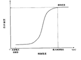
- 4 is a graph showing changes in stimulus responses to stimulation currents in healthy subjects.
- 7 is a graph showing changes in stimulation responses to stimulation currents of healthy subjects, etc., measured by the muscle relaxation monitoring device according to the second embodiment of the present invention.
- FIG. 10 is a flow chart showing the processing operation for determining suitability as a monitoring target in the muscle relaxation monitoring device according to the second embodiment of the present invention.
- FIG. FIG. 11 is a flow chart showing another example of the processing operation for determining suitability as a monitoring target in the muscle relaxation monitoring device according to the second embodiment of the present invention;
- FIG. 1 is an overall configuration diagram showing a schematic configuration of a muscle relaxation monitoring device according to this embodiment
- FIG. 2 is a device block diagram of the body of the muscle relaxation monitoring device according to this embodiment
- FIG. 3 is a flow chart showing the optimum current value determination processing operation in the muscle relaxation monitoring device according to the present embodiment.
- the muscle relaxation monitoring device 1 includes a main body 10 fixed and supported on the forearm of a patient 100 via a band 50 or the like, and attached to the forearm of the patient 100 in the vicinity of the ulnar nerve. Electrode clips 20 and 21 corresponding to the current stimulator, which supply stimulation current to the ulnar nerve via 40 and 41, and the distal node and thumb near the adductor pollicis muscle of the patient 100 via wiring 42.
- a myoelectric sensor 30 corresponding to a reaction detection unit that is attached to a ball and measures myoelectric potential, and a myoelectric sensor 30 that is integrally configured and attached to the end of the thumb of the patient 100 to measure changes in muscle acceleration. and an acceleration sensor 31 corresponding to the reaction detection unit.
- the muscle relaxation monitoring device 1 is connected wirelessly or by wire to a medical telemeter or the like (not shown).
- the main unit 10 includes operation buttons 10a as an operation unit for inputting various instructions from the medical staff, and a display 10b for displaying setting menus, operation menus, and the like.
- the display 10b is a color display such as an LCD (Liquid Crystal Display), an organic EL (Electro Luminescence), or a monochrome display. Note that the operation buttons 10a and the display 10b may be configured integrally like a so-called touch panel.
- the electrode clips 20 and 21 are attached to the forearm (wrist side) near the ulnar nerve of the patient's 100 hand via the electrode pads 22 and 23 .
- An adhesive may be applied to the surfaces of the electrode pads 22 and 23 in order to ensure attachment to the patient 100 .
- the myoelectric sensor 30 is composed of electrode pads 30a and 30b and a ground electrode 30c, which are attached to the distal joint of the thumb and the ball of the thumb near the adductor muscle of the thumb.
- the acceleration sensor 31 is configured integrally with the electrode pad 30 a of the myoelectric sensor 30 and attached to the distal joint of the thumb of the patient 100 .
- the acceleration sensor 31 may be, for example, a triaxial acceleration sensor.
- a triaxial acceleration sensor is used as the acceleration sensor 31, the sum of orthogonal three-direction vectors of the 3D sensor is detected as the momentum.
- the acceleration sensor 31 (or the myoelectric sensor 30) is used as a reaction detection unit in this way, the arm and hand, which are necessary when the strength of the force applied from the thumb is detected by a strain gauge, can be fixed. Since a fixed stand or the like is not required, the device can be made smaller.
- Combinations of the mounting positions of the electrode clips 20 and 21, the myoelectric sensor 30, and the acceleration sensor 31 include ulnar nerve/adductor pollicis muscle, ulnar nerve/abductor little finger, ulnar nerve/first dorsal bone. It should be placed on a neuromuscular site that avoids direct stimulation of muscles such as the intermuscular, posterior tibial nerve/flexor hallucis brevis, facial nerve/orbicularis oculi, facial nerve/corrugator muscle, and more clearly detectable twitches. may
- the wirings 40 to 42 are converged as a wiring bundle in an insulated state, compacted, and connected to the main body 10 .
- the stimulation electrodes (corresponding to the electrode pads 22 and 23), the myoelectric sensor 30 and the acceleration sensor 31 may be configured to be wirelessly connected to the main body 10. Moreover, it is good also as a structure provided integrally with the stimulation electrode, the myoelectric sensor 30, and the acceleration sensor 31.
- FIG. 1 A schematic diagram illustrating an exemplary computing environment in accordance with the present disclosure.
- the muscle relaxation monitoring device 1 includes a current stimulator 11 that supplies a stimulating current to the muscles of a patient 100, and a response detector 12 that detects the stimulus response of the muscle stimulated by the current stimulator 11. , a storage unit 13 for recording the stimulus current supplied to the muscle of the patient 100 with stepwise increase before the injection of the muscle relaxant, and the stimulus response corresponding to the stimulus current value; and a control unit 14 for determining the stimulation current value immediately before saturation in the case where the stimulation current value is the optimum current value to be supplied to the patient 100 after administration of the muscle relaxant.
- the muscle relaxation monitoring device 1 further includes an operation unit 15, a display unit 16, an input/output unit 17, and the like.
- the current stimulation unit 11 corresponding to the electrode clips 20 and 21 supplies a predetermined stimulation current (details will be described later) in a predetermined stimulation pattern to the muscles of the patient 100 based on commands from the control unit 14. .
- the stimulation pattern can be appropriately selected from twitch stimulation, TOF (Train Of Four) stimulation, double burst stimulation, tetanus stimulation, post-tetanic count (PTC), and the like.
- TOF Train Of Four
- PTC post-tetanic count
- TOF stimulation is, for example, a set of 4 consecutive stimulations every 0.5 seconds, which is repeated to stimulate the target nerve.
- the stimulation frequency is 2 times/second, corresponding to 2 Hz.
- An appropriate time interval (eg, 10 to 20 seconds) is set between each set to regenerate the responsiveness to the stimulation of the nerve.
- a reaction detection unit 12 corresponding to the myoelectric sensor 30 and the acceleration sensor 31 detects the stimulation reaction of the muscle stimulated by the current stimulation unit 11 .
- stimulation responses stimulation intensity
- T 1 first muscle contraction
- T 4 fourth muscle contraction
- It is detected as an electric signal from the myoelectric sensor 30 and the acceleration sensor 31 arranged at the end joint of the thumb of the patient 100 .
- An electrical signal from the myoelectric sensor 30 is amplified by an amplifier (not shown) and transmits a stimulus response to the response detection unit 12 .
- the response detection unit 12 transmits the detected stimulation responses of T 1 to T 4 to the control unit 14 .
- the control unit 14 stores a CPU (central processing unit) that performs various controls of the muscle relaxation monitoring device 1, various programs that the CPU executes to control the muscle relaxation monitoring device 1, an internal memory that stores various data, and the like. Prepare.
- the control unit 14 reads data and programs stored in the internal memory, performs various arithmetic processing, and realizes various functions.
- the control unit 14 stores the value of the stimulation current supplied to the muscle of the patient 100 via the current stimulation unit 11 in the storage unit 13, and the stimulation response corresponding to the supplied stimulation current value transmitted from the reaction detection unit 12. is stored in the storage unit 13 . Also, as will be described later, among the measurement data stored in the storage unit 13, the stimulation current value immediately before the stimulation response is saturated is determined as the optimum current value to be supplied to the patient 100 after administration of the muscle relaxant.
- the operation unit 15 corresponding to the operation button 10a is an interface for performing various inputs to the muscle relaxation monitoring device 1.
- the display unit 16 corresponding to the display 10b displays the execution program that the muscle relaxation monitoring device 1 performs to the patient 100, the stimulation current value and stimulation pattern that are supplied to the patient 100, and the detection by the myoelectric sensor 30 and the acceleration sensor 31. display the stimulus response, etc.
- the input/output unit 17 transmits and receives data to and from a medical telemeter wirelessly or via cable.
- the input/output unit 17 is composed of an antenna, an electrical connector, and the like.
- the input/output unit 17 transmits the stimulus current value supplied to the patient 100, the stimulus reaction detected by the reaction detection unit 12, and the like to the medical telemeter.
- Either the myoelectric sensor 30 or the acceleration sensor 31 may be used as a sensor corresponding to the reaction detection unit 12, but the case where the acceleration sensor 31 is used will be described below as an example.
- the operation button 10a on the main unit 10 of the muscle relaxation monitoring device 1 attached to the patient 100 before administering the muscle relaxant to select the measurement menu of the optimum current value of the patient 100 the operation An input signal is transmitted from the unit 15 to the control unit 14 . Then, the control unit 14 sends a command to the current stimulation unit 11 to supply the stimulation current initial value to the patient 100 in a predetermined stimulation pattern (step S100).
- the patient 100 is subjected to nerve stimulation with TOF stimulation as the stimulation pattern and 10 mA as the initial stimulation current value.
- the response detection unit 12 receives an electrical signal (stimulation response) from the acceleration sensor 31 due to muscle contraction of the patient 100, it transmits the stimulation response to the control unit 14 (step S110).
- the control unit 14 temporarily stores the stimulation current value transmitted to the current stimulation unit 11 and the stimulation response corresponding to the stimulation current value in the storage unit 13 at least until the operation of determining the optimum current value is completed (step S120).
- the control unit 14 sets the stimulation response in the first muscle contraction (T 1 ) as the stimulation response corresponding to the stimulation current value, and the storage unit 13 store in
- control unit 14 determines whether or not the stimulus response transmitted from the reaction detection unit 12 has exceeded a predetermined value (step S130).
- the predetermined value of the stimulus response is the value when the stimulus response is saturated with respect to the supplied stimulus current. As shown in FIG. 4, the stimulation response to the stimulation current saturates at a constant value ( does not change). In this embodiment, this saturated stimulus response is used as the predetermined value of the stimulus response.
- step S130 If the stimulus response does not exceed the predetermined value (step S130: NO), the controller 14 newly sets a stimulus current value obtained by stepwise increasing the stimulus current initial value (step S160). Steps S110 to S130 and S160 are repeatedly executed until the predetermined value is exceeded.
- a stimulation current increased by 5 mA from the initial stimulation current value of 10 mA is supplied to the patient 100 to stimulate nerves, and the stimulation response is predetermined. Nerve stimulation is repeated while stepwise increasing the stimulation current by 5 mA at 1 second intervals until the value is exceeded.
- step S130 When the stimulus response exceeds the predetermined value (step S130: YES), the control unit 14 stops the supply of the stimulation current to the patient 100, and the stimulus response stored in the storage unit 13 exceeds the predetermined value.
- the stimulation current value immediately before exceeding is determined as the optimum current value (step S140), the optimum current value is stored in the storage unit 13 (step S150), and the optimum current value decision processing operation is terminated.
- the stimulus response exceeds a predetermined value at a stimulus current of 45 mA, 40 mA, which is the stimulus current value immediately before that, is determined and stored as the optimum current value.
- the optimum current value determined in this way is displayed on the display 10b.
- control unit 14 may transmit the determined optimum current value to the medical telemeter via the input/output unit 17, and the medical telemeter may store and display it in association with the patient information.
- the optimal current value determined as described above is used to grasp the muscle relaxation state and recovery state of the patient 100 with the acceleration sensor 31 .
- the control unit 14 may perform normalization processing (normalize) before surgery (before administering a muscle relaxant).
- the control unit 14 For grasping the muscle relaxation state and recovery state of the patient 100 by the acceleration sensor 31, for example, when the recovery state of the patient 100 is determined using TOF stimulation as a stimulation pattern, the control unit 14 first detects the optimal current value of the patient 100. from the storage unit 13, and instructs the current stimulation unit 11 to supply the stimulation current to the patient 100 at the optimum current value.
- the current stimulation unit 11 stimulates the nerves of the patient 100 via the electrode clips 20 and 21
- the reaction detection unit 12 receives the muscle contraction of the patient 100 in response to the nerve stimulation as an electric signal from the acceleration sensor 31 .
- the control unit 14 determines the stimulus response of the fourth muscle contraction (T 4 ) with respect to the stimulus response of the first muscle contraction (T 1 ).
- a ratio (TOF ratio: T 4 /T 1 ) is calculated. Since the stimulus response gradually decreases from the first time to the fourth time, the recovery state of the patient 100 can be easily grasped by observing the TOF ratio. For example, when the TOF ratio satisfies the condition of T 4 /T 1 >0.9 (after normalization processing), the control unit 14 determines that the patient 100 is in a recovery state, and displays this on the display 10b. and displayed on the medical telemeter via the input/output unit 17. In response to this, the medical staff removes the artificial respirator intubated from the patient 100, and the monitoring of the muscle relaxation state of the patient 100 ends.
- the stimulating current supplied to the muscle of the patient 100 with stepwise increase before injection of the muscle relaxant and the stimulating response corresponding to the stimulating current value are recorded in the storage unit 13, and controlled. Since the unit 14 determines the stimulation current value immediately before saturation as the optimum current value to be supplied to the patient 100 after administration of the muscle relaxant, the stimulation current to be supplied can be determined according to the individual patient, The stimulation current value immediately before saturation, in which the burden on the patient for electrical stimulation is small and the muscle relaxation state can be accurately detected, is set as the optimum current value, and the muscle relaxation state can be accurately detected without imposing an excessive burden on the patient 100. can be monitored.
- FIG. 5 is a graph showing changes in stimulus responses to stimulation currents of healthy subjects, etc., measured by the muscle relaxation monitoring device according to the present embodiment.
- FIG. FIG. 7 is a flow chart showing the suitability determination processing operation as a monitoring target, and FIG. In this embodiment, explanations that overlap with those of the first embodiment will be omitted.
- the control unit 14 calculates the amount of change in the stimulation response to the stimulation current before administration of the muscle relaxant in the vicinity of the initial supply of the stimulation current, the vicinity of saturation, and the middle thereof. Whether or not the patient is suitable as a monitoring target is determined based on the amount of change.
- patients with abnormalities in joints and muscles such as rheumatoid arthritis patients and muscle atrophy patients (for example, dialysis patients), show different stimulation responses than patients without such abnormalities (hereafter referred to as healthy subjects).
- region A is set in the range of stimulation current from 15 to 30 mA, but is not limited to this, and is appropriately set based on the stimulation current-stimulus response curve exhibited by healthy subjects. That is, the amounts of change RA to RC in the stimulus response to the stimulus current value in each region of healthy subjects show the following relationships.
- the amount of change in stimulation response to stimulation current in each region is calculated from any two continuous or discontinuous measurement data out of a plurality of data including data on the boundary with adjacent regions. is.
- selecting data with a large difference between the stimulating current value C1 and the stimulating current value C2 in each region more prominently represents the characteristics of the approximated curve in each region. Therefore, it is preferable.
- all the amounts of change for two consecutive measurement data may be calculated, and the average value of these may be used as the (average) amount of change in stimulus response to the stimulus current.
- the stimulation response to the stimulation current differs between healthy subjects and patients with rheumatoid arthritis/muscular atrophy, and sufficient stimulation responses cannot be observed. This means that patients with rheumatoid arthritis and muscle atrophy are not suitable subjects for muscle relaxation monitoring using an acceleration sensor.
- the muscle relaxation monitoring device 1 determines whether or not the patient 100 is suitable as a monitoring target from the amount of change in stimulus response to the stimulus current.
- This suitability determination processing operation is performed in parallel with the optimum current value determination processing operation described in the first embodiment, but is not limited to this.
- control unit 14 determines the stimulus response to the stimulation current in preset regions A to C based on the stimulation current value transmitted to the current stimulation unit 11 and the corresponding stimulation response received from the reaction detection unit 12. is calculated at any time (step S200).
- the stimulation current values for regions A to C are set as region A: 10 to 15 mA, region B: 15 to 30 mA, and region C: 30 mA to maximum stimulation current value.
- step S210 when the calculated amount of change satisfies R A ⁇ R B and R C ⁇ R B (step S210: YES), the patient 100 is a healthy subject, and therefore the monitoring target in the muscle relaxation monitoring device 1 is (step S220), the fact is displayed on the display 10b, the medical telemeter, etc., and the suitability determination processing operation is terminated. If the patient 100 is determined to be suitable as a monitoring target, the acceleration sensor 31 uses the optimum current value determined in the optimum current value determination processing operation to monitor the muscle of the patient 100 even after administration of the muscle relaxant. Understand the state of relaxation and recovery.
- step S210 If the calculated amount of change does not satisfy R A ⁇ R B and R C ⁇ R B (step S210: NO), it is determined that the patient 100 is inappropriate as a monitoring target for the muscle relaxation monitoring device 1 (step S230), and the effect is displayed on the display 10b, the medical telemeter, or the like. At this time, the inappropriateness may be notified to the medical staff by a warning sound or the like.
- the empirical rule by the medical staff or the conventionally adopted default stimulation current (for example, the same stimulation current value for all patients) Based on this, the muscle relaxation state of the patient 100 is grasped.
- the reason why the patient 100 is determined to be inappropriate as a monitoring target is that accurate data cannot be obtained due to the failure of the acceleration sensor 31 or the like.
- there are other factors such as rubbing against sheets during surgery, stress from the outside, and movement (body movement) of a part other than the thumb, which causes the acceleration sensor 31 to react.
- the control unit 14 determines the transition from the acceleration sensor 31 to the myoelectric sensor 30 as means for determining the optimum current value of the patient 100 before administering the muscle relaxant (step S240). may be configured to notify the medical staff by an alarm sound or the like. As described above, the suitability determination processing operation is completed.
- the control unit 14 switches from the acceleration sensor 31 to the myoelectric sensor 30 as a medium for detecting the stimulus response of the patient 100 as the reaction detection unit 12, and uses the myoelectric sensor 30.
- the optimum current value determination processing operation and suitability determination processing operation (excluding the determination of transition to the myoelectric sensor) are performed.
- the patient 100 is determined to be suitable as a monitoring target in the suitability determination processing operation (that is, when the acceleration sensor 31 has a cause such as a failure)
- the optimal current value The myoelectric sensor 30 grasps the muscle relaxation state and recovery state of the patient 100 using the optimum current value determined in the determination processing operation. , the muscle relaxation state of the patient 100 is grasped based on empirical rules by medical staff and default stimulation currents conventionally adopted.
- the determination condition is whether or not both conditions RA ⁇ RB and RC ⁇ RB are satisfied. You may make it determine whether it is appropriate.
- the patient 100 is a patient with rheumatoid arthritis/muscular atrophy, there is almost no difference in size between the RA in the region A and the RB in the region B. If the threshold is not exceeded due to the relationship, it can be determined that it is inappropriate as a monitoring target.
- RA in region A and RB in region B are RA If ⁇ n ⁇ RB is satisfied (step S310: YES), it is determined that the patient 100 is suitable as a monitoring target in the muscle relaxation monitoring device 1 (step S220), and RA ⁇ n ⁇ RB is not satisfied. If so (step S310: NO), it is determined that the patient 100 is inappropriate as a monitoring target for the muscle relaxation monitoring device 1 (step S230).
- n is appropriately set to at least a value of 1 or more.
- the subsequent optimum current value determination processing operation can be interrupted or stopped at the time when it is determined to be inappropriate. , there is no need to supply an extra stimulation current to the patient 100 who is unsuitable as a monitoring target, and the burden of the stimulation current on the patient 100 can be reduced.
- the measurement data and/or the approximate curve derived from the measurement data may be displayed on the display 10b, the medical telemeter, or the like. This allows the medical staff to visually determine whether the patient 100 is suitable for monitoring.
- whether or not the patient 100 is suitable as a monitoring target is determined based on the amount of change in stimulation response to the stimulation current.
- Patients can be distinguished from patients (healthy subjects) who do not suffer from these diseases, and there is an effect that only healthy subjects suitable for monitoring by the apparatus can be selectively monitored.
- the control unit 14 that determines the transition to the myoelectric sensor 30 as the reaction detection unit 12 is provided.
- the monitoring target is inappropriate due to a failure of the acceleration sensor 31, etc.
- monitoring of the muscle relaxation state by the myoelectric sensor 30 that does not depend on changes in the acceleration of the muscle is encouraged, and the patient can be more reliably monitored. It has the effect of being able to grasp 100 muscle relaxation states.
- the muscle relaxation monitoring device 1 determines whether or not the acceleration sensor 31 is faulty after the muscle relaxation monitoring device 1 is activated.
- the acceleration sensor 31 may not be able to output a normal output value due to an error in the output value due to acceleration exceeding the rating due to being dropped or being hit during transportation. In such a state, even if the optimal current value determination processing operation and the propriety determination processing operation are performed, the patient 100 is only burdened unnecessarily.
- failure determination processing for the acceleration sensor 31 is performed before the optimal current value determination processing operation and the propriety determination processing operation are performed.
- the control unit 14 receives the output signal from the acceleration sensor 31 due to the excitation of the vibrator via the reaction detection unit 12, and if the output signal is larger than the threshold, the acceleration sensor 31 is out of order. If the output signal is smaller than the threshold value, it is determined that the acceleration sensor 31 is out of order (defective product), and the failure determination process ends.
- the control unit 14 displays the determination result on the display 10b or the medical telemeter, and if it determines that the acceleration sensor 31 is out of order, it notifies the medical staff of this by an alarm sound or the like.
- control unit 14 determines the transition from the acceleration sensor 31 to the myoelectric sensor 30 as the reaction detection unit 12, and notifies the medical staff of this. can be
- the acceleration sensor 31 as the reaction detection unit 12 was used as an example to describe the optimum current value determination processing operation and suitability determination processing operation, but the myoelectric sensor 30 may be used. That is, without using the acceleration sensor 31, the myoelectric sensor 30 may be used as the reaction detection unit 12 to perform the optimum current value determination processing operation and the propriety determination processing operation (excluding the determination of transition to the myoelectric sensor). .
- control unit 14 may perform notification processing for notifying the medical staff that the TOF ratio has reached a predetermined value by means of an alarm sound or the like. For example, if the TOF ratio T 4 /T 1 exceeds 0.25, there is a possibility that the patient 100 will move, which may interfere with surgery. Therefore, one or more TOF ratios that interfere with surgery are input and set in the muscle relaxation monitoring device 1 (internal memory, etc.) in advance, and the TOF ratio measured during surgery is compared with the set TOF ratio. In such a case, the medical staff may be notified by an alarm sound or the like.
- muscle relaxation monitoring device 10 main unit 10a operation button 10b display 11 current stimulation unit 12 reaction detection unit 13 storage unit 14 control unit 15 operation unit 16 display unit 17 input/output unit 20, 21 electrode clips 22, 23 electrode pad 30 myoelectric potential Sensors 30a, 30b Electrode pad 30c Earth electrode 31 Acceleration sensors 40, 41, 42 Wiring 50 Band 100 Patient
Landscapes
- Health & Medical Sciences (AREA)
- Life Sciences & Earth Sciences (AREA)
- Engineering & Computer Science (AREA)
- Medical Informatics (AREA)
- Physics & Mathematics (AREA)
- Veterinary Medicine (AREA)
- Biophysics (AREA)
- Pathology (AREA)
- Public Health (AREA)
- Biomedical Technology (AREA)
- Heart & Thoracic Surgery (AREA)
- General Health & Medical Sciences (AREA)
- Molecular Biology (AREA)
- Surgery (AREA)
- Animal Behavior & Ethology (AREA)
- Oral & Maxillofacial Surgery (AREA)
- Physiology (AREA)
- Dentistry (AREA)
- Measurement And Recording Of Electrical Phenomena And Electrical Characteristics Of The Living Body (AREA)
Abstract
Priority Applications (1)
| Application Number | Priority Date | Filing Date | Title |
|---|---|---|---|
| JP2023512936A JPWO2022215546A1 (fr) | 2021-04-06 | 2022-03-24 |
Applications Claiming Priority (2)
| Application Number | Priority Date | Filing Date | Title |
|---|---|---|---|
| JP2021064510 | 2021-04-06 | ||
| JP2021-064510 | 2021-04-06 |
Publications (1)
| Publication Number | Publication Date |
|---|---|
| WO2022215546A1 true WO2022215546A1 (fr) | 2022-10-13 |
Family
ID=83545394
Family Applications (1)
| Application Number | Title | Priority Date | Filing Date |
|---|---|---|---|
| PCT/JP2022/014069 WO2022215546A1 (fr) | 2021-04-06 | 2022-03-24 | Dispositif de surveillance de relaxation musculaire |
Country Status (2)
| Country | Link |
|---|---|
| JP (1) | JPWO2022215546A1 (fr) |
| WO (1) | WO2022215546A1 (fr) |
Citations (5)
| Publication number | Priority date | Publication date | Assignee | Title |
|---|---|---|---|---|
| JP2000342690A (ja) * | 1999-06-09 | 2000-12-12 | Nippon Colin Co Ltd | 麻酔深度監視装置 |
| US20120245482A1 (en) * | 2010-09-16 | 2012-09-27 | Bolser Jeffrey W | Anesthesia Monitoring Device and Method |
| JP2015066401A (ja) * | 2013-10-01 | 2015-04-13 | 公益財団法人ヒューマンサイエンス振興財団 | 興奮収縮連関の障害の有無の判定補助方法 |
| JP2019530528A (ja) * | 2016-10-14 | 2019-10-24 | ブリンク デバイス, エルエルシーBlink Device, Llc | 定量的神経筋系遮断検知システム及び方法 |
| US20210076982A1 (en) * | 2019-09-12 | 2021-03-18 | GE Precision Healthcare LLC | Method and System for Monitoring Depth of Muscle Relaxation of a Patient |
-
2022
- 2022-03-24 WO PCT/JP2022/014069 patent/WO2022215546A1/fr active Application Filing
- 2022-03-24 JP JP2023512936A patent/JPWO2022215546A1/ja active Pending
Patent Citations (5)
| Publication number | Priority date | Publication date | Assignee | Title |
|---|---|---|---|---|
| JP2000342690A (ja) * | 1999-06-09 | 2000-12-12 | Nippon Colin Co Ltd | 麻酔深度監視装置 |
| US20120245482A1 (en) * | 2010-09-16 | 2012-09-27 | Bolser Jeffrey W | Anesthesia Monitoring Device and Method |
| JP2015066401A (ja) * | 2013-10-01 | 2015-04-13 | 公益財団法人ヒューマンサイエンス振興財団 | 興奮収縮連関の障害の有無の判定補助方法 |
| JP2019530528A (ja) * | 2016-10-14 | 2019-10-24 | ブリンク デバイス, エルエルシーBlink Device, Llc | 定量的神経筋系遮断検知システム及び方法 |
| US20210076982A1 (en) * | 2019-09-12 | 2021-03-18 | GE Precision Healthcare LLC | Method and System for Monitoring Depth of Muscle Relaxation of a Patient |
Also Published As
| Publication number | Publication date |
|---|---|
| JPWO2022215546A1 (fr) | 2022-10-13 |
Similar Documents
| Publication | Publication Date | Title |
|---|---|---|
| KR102491756B1 (ko) | 신경근 신호를 처리하는 장치, 방법, 및 시스템 | |
| US7326181B2 (en) | Nervous tissue stimulation device and method | |
| KR101929720B1 (ko) | 연하 장해 검사 장치, 연하 장해 검사 방법, 연하 장해 치료 장치 및 자극 전류 설정 방법 | |
| US20130204156A1 (en) | Methods and Systems For Assessing Muscle Electrical Activity in Response to Stimulation of a Motor Nerve | |
| US20130204155A1 (en) | Anesthesia Monitoring Systems and Methods of Monitoring Anesthesia | |
| KR20140084240A (ko) | 전기 자극 장치 및 전기 자극 장치 시스템 | |
| CZ308216B6 (cs) | Zařízení pro měření svalové síly a způsob testování svalového výkonu sportovců | |
| US11980461B2 (en) | Method and system for monitoring depth of muscle relaxation of a patient | |
| JP2011182954A (ja) | 排尿障害治療器 | |
| WO2022215546A1 (fr) | Dispositif de surveillance de relaxation musculaire | |
| US20240180476A1 (en) | Muscular relaxation monitoring device | |
| US9333348B2 (en) | Apparatus for determining optimum treatment parameters | |
| CA2923230C (fr) | Technique pour determiner des parametres de traitement optimaux | |
| US20230109161A1 (en) | Systems and methods for reducing spasticity after neurological injury | |
| US20220401007A1 (en) | Muscle relaxation monitoring apparatus and calibration processing method |
Legal Events
| Date | Code | Title | Description |
|---|---|---|---|
| 121 | Ep: the epo has been informed by wipo that ep was designated in this application |
Ref document number: 22784531 Country of ref document: EP Kind code of ref document: A1 |
|
| ENP | Entry into the national phase |
Ref document number: 2023512936 Country of ref document: JP Kind code of ref document: A |
|
| WWE | Wipo information: entry into national phase |
Ref document number: 18285145 Country of ref document: US |
|
| NENP | Non-entry into the national phase |
Ref country code: DE |
|
| 122 | Ep: pct application non-entry in european phase |
Ref document number: 22784531 Country of ref document: EP Kind code of ref document: A1 |