WO2022215145A1 - 覚醒努力動作推定装置および覚醒努力動作推定方法 - Google Patents
覚醒努力動作推定装置および覚醒努力動作推定方法 Download PDFInfo
- Publication number
- WO2022215145A1 WO2022215145A1 PCT/JP2021/014559 JP2021014559W WO2022215145A1 WO 2022215145 A1 WO2022215145 A1 WO 2022215145A1 JP 2021014559 W JP2021014559 W JP 2021014559W WO 2022215145 A1 WO2022215145 A1 WO 2022215145A1
- Authority
- WO
- WIPO (PCT)
- Prior art keywords
- unit
- mask
- captured image
- face
- driver
- Prior art date
- Legal status (The legal status is an assumption and is not a legal conclusion. Google has not performed a legal analysis and makes no representation as to the accuracy of the status listed.)
- Ceased
Links
Images


Classifications
-
- A—HUMAN NECESSITIES
- A61—MEDICAL OR VETERINARY SCIENCE; HYGIENE
- A61B—DIAGNOSIS; SURGERY; IDENTIFICATION
- A61B5/00—Measuring for diagnostic purposes; Identification of persons
- A61B5/16—Devices for psychotechnics; Testing reaction times ; Devices for evaluating the psychological state
- A61B5/18—Devices for psychotechnics; Testing reaction times ; Devices for evaluating the psychological state for vehicle drivers or machine operators
-
- A—HUMAN NECESSITIES
- A61—MEDICAL OR VETERINARY SCIENCE; HYGIENE
- A61B—DIAGNOSIS; SURGERY; IDENTIFICATION
- A61B5/00—Measuring for diagnostic purposes; Identification of persons
- A61B5/103—Measuring devices for testing the shape, pattern, colour, size or movement of the body or parts thereof, for diagnostic purposes
- A61B5/11—Measuring movement of the entire body or parts thereof, e.g. head or hand tremor or mobility of a limb
- A61B5/1126—Measuring movement of the entire body or parts thereof, e.g. head or hand tremor or mobility of a limb using a particular sensing technique
- A61B5/1128—Measuring movement of the entire body or parts thereof, e.g. head or hand tremor or mobility of a limb using a particular sensing technique using image analysis
-
- G—PHYSICS
- G06—COMPUTING OR CALCULATING; COUNTING
- G06T—IMAGE DATA PROCESSING OR GENERATION, IN GENERAL
- G06T7/00—Image analysis
- G06T7/20—Analysis of motion
-
- G—PHYSICS
- G06—COMPUTING OR CALCULATING; COUNTING
- G06V—IMAGE OR VIDEO RECOGNITION OR UNDERSTANDING
- G06V40/00—Recognition of biometric, human-related or animal-related patterns in image or video data
- G06V40/10—Human or animal bodies, e.g. vehicle occupants or pedestrians; Body parts, e.g. hands
- G06V40/16—Human faces, e.g. facial parts, sketches or expressions
- G06V40/174—Facial expression recognition
-
- G—PHYSICS
- G08—SIGNALLING
- G08G—TRAFFIC CONTROL SYSTEMS
- G08G1/00—Traffic control systems for road vehicles
- G08G1/16—Anti-collision systems
Definitions
- the present disclosure relates to an awakening effort motion estimation device and an awakening effort motion estimation method for estimating whether or not a vehicle occupant is performing an awakening effort motion.
- the awakening effort motions include those by moving the mouth, such as yawning.
- PMS Passenger Monitoring System
- Patent Literature 1 a technique for estimating whether or not the occupant is in a low wakefulness state. It should be noted that the level of arousal of a person does not change monotonously from the state in which the person is awake until the level of arousal declines until the person falls asleep, and the level of the level of arousal increases when the person performs an effort to awaken. Are known. By estimating a person's awakening level reduction state according to the presence or absence of an awakening effort motion, a person's awakening level reduction state can be estimated with high accuracy.
- the awakening effort motion estimation device includes a captured image acquisition unit that acquires a captured image of the face of a vehicle occupant, and based on the captured image acquired by the captured image acquisition unit, one point in the captured image.
- Two points for estimating the movement of the occupant's mouth a point on the mask worn by the occupant, the other point based on the feature points of the occupant's face, or a point different from the one point on the mask.
- a reference point detection unit that detects a reference point
- a distance calculation unit that calculates a reference point distance between two reference points detected by the reference point detection unit, and a reference point distance calculated by the distance calculation unit for estimating arousal effort.
- a motion estimating unit for estimating whether or not the occupant is making an awakening effort motion by moving the mouth depending on whether or not a condition is satisfied.
- a camera 2 is mounted on a vehicle 3 .
- the camera 2 is installed in the central part of the instrument panel of the vehicle 3, the meter panel, or the like, for the purpose of monitoring the interior of the vehicle.
- the camera 2 is installed so as to be able to capture at least the face of the occupant.
- the camera 2 is assumed to be shared with a so-called PMS (Passenger Monitoring System).
- Camera 2 is a visible light camera or an infrared camera.
- the infrared camera is provided with a light source (not shown) that irradiates infrared rays for imaging to a range including the passenger's face.
- This light source is composed of, for example, an LED (Light Emitting Diode).
- LED Light Emitting Diode
- Camera 2 outputs a captured image (hereinafter referred to as “captured image”) to awakening effort motion estimation device 1 .
- the awakening effort motion estimation device 1 estimates whether or not the occupant wearing the mask performs an awakening effort motion by moving the mouth based on the captured image acquired from the camera 2 .
- the awakening effort motion estimation device 1 estimates the awakening degree reduction state of the passenger based on the estimation result of the awakening effort indicating whether or not the passenger wearing the mask performs the awakening effort motion by moving the mouth.
- the occupant is assumed to be the driver of the vehicle 3 .
- the device 1 for estimating arousal effort motion can also target a passenger other than the driver of the vehicle 3 for estimating whether or not the person is performing an effortful awakening motion by moving the mouth.
- the driver of the vehicle 3 will be simply referred to as "driver”.
- the awakening effort motion by moving the mouth is also simply referred to as "awakening effort motion”.
- a captured image acquisition unit 101 acquires a captured image from the camera 2 .
- the captured image acquisition unit 101 outputs the acquired captured image to the face detection unit 102 and the mask detection unit 103 .
- the face detection unit 102 detects the driver's face and parts of the driver's face based on the captured image acquired by the captured image acquisition unit 101 . Specifically, based on the captured image acquired by the captured image acquisition unit 101, the face detection unit 102 detects the driver's face in the captured image, and detects feature points of the driver's face that indicate parts of the driver's face. To detect.
- the parts of the face include the outer corners of the eyes, the inner corners of the eyes, the nose, the chin, the top of the head, and the like.
- the face detection unit 102 detects feature points of the driver's face using a face detector based on a known general algorithm that combines a Haar-Like detector with Adaboost or Casecade.
- the face detector has previously learned a large amount of face image data.
- the face detection unit 102 may detect feature points of the driver's face using a general method such as so-called model fitting or Elastic Bunch Graph Matching.
- the face detection unit 102 can detect feature points of the driver's face based on the captured image using various known face recognition techniques.
- feature points on the driver's face are represented by coordinates on the captured image.
- the face detection unit 102 adds information that can specify which part of the face the feature points represent to the feature points of the driver's face, and detects the facial features of the driver.
- a captured image (hereinafter referred to as a “captured image with facial feature points”) to which information that can specify which part of the face the feature points represent is added to the feature points is output to the reference point detection unit 104 .
- the awakening effort motion estimation device 1 includes the face detection unit 102 here, this is merely an example, and the awakening effort motion estimation device 1 does not necessarily include the face detection unit 102 .
- the face detection unit 102 may be provided outside the arousal effort motion estimation device 1 at a location where the arousal effort motion estimation device 1 can refer to.
- camera 2 may include face detection unit 102 .
- the camera 2 outputs the captured image with facial feature points to the awakening effort motion estimation device 1 .
- the captured image acquisition unit 101 acquires the captured image with facial feature points output from the camera 2 and outputs the acquired captured image with facial feature points to the reference point detection unit 104 . Details of the reference point detection unit 104 will be described later.
- the mask detection unit 103 detects the mask worn by the driver based on the captured image acquired by the captured image acquisition unit 101 . Specifically, the mask detection unit 103 detects an area in which the mask worn by the driver is captured in the captured image.
- the mask detection unit 103 may detect the mask worn by the driver, for example, using a known image recognition technique. For example, the mask detection unit 103 may detect the mask worn by the driver using a face detector based on a general algorithm used by the face detection unit 102 to detect feature points on the driver's face. In this case, it is assumed that a large amount of face image data for learning by the face detector includes face image data for wearing a mask.
- Masks include masks made of different types of materials, such as non-woven fabric masks, cloth masks, and urethane masks. Also, the mask is available in various colors. Moreover, the mask includes a patterned mask and a non-patterned mask. When a face detector is used to detect the mask worn by the driver, it is preferable to have the face detector learn face image data in which many types of masks are worn.
- the mask worn by the driver is represented by an area on the captured image.
- the mask detection unit 103 adds information that can identify the area of the mask worn by the driver to the area of the mask worn by the driver.
- a captured image (hereinafter referred to as “captured image with masked area”) to which information that can identify the masked area is added to the masked area is output to the reference point detection unit 104 .
- the awakening effort motion estimation device 1 includes the mask detection unit 103 here, this is merely an example, and the awakening effort motion estimation device 1 does not necessarily include the mask detection unit 103 .
- the mask detection unit 103 may be provided at a location outside the arousal effort estimation device 1 that can be referred to by the arousal effort estimation device 1 .
- the camera 2 may have the mask detection section 103 . In this case, the camera 2 outputs the captured image with the mask area to the awakening effort motion estimation device 1 .
- the captured image acquisition unit 101 acquires the captured image with the mask area output from the camera 2 and outputs the acquired captured image with the mask area to the reference point detection unit 104 . Details of the reference point detection unit 104 will be described later.
- the reference point detection unit 104 Based on the captured image acquired by the captured image acquisition unit 101, the reference point detection unit 104 detects one point in the captured image as a point on the mask worn by the driver and the other point as a feature point of the driver's face. A point or two reference points for estimating the movement of the driver's mouth are detected that are different from one point in the mask. More specifically, based on the captured image with facial feature points output from the face detection unit 102 and the captured image with mask area output from the mask detection unit 103, the reference point detection unit 104 detects one side of the captured image.
- the other point is a point based on the feature points of the driver's face or a point different from the one point on the mask, to estimate the movement of the driver's mouth.
- two reference points are detected.
- the arousal effort motion estimation device 1 can estimate the movement of the mouth moved by the driver while wearing the mask by focusing on how the mask worn by the driver moves in the captured image.
- the reference point detection unit 104 detects the two reference points in the captured image so that the movement of the mask can be detected when the driver moves the mouth while wearing the mask.
- FIGS. 2A, 2B, and 2C are diagrams for explaining the movement pattern of the mask in the captured image when the driver moves the mouth while wearing the mask.
- the faces shown in FIGS. 2A, 2B, and 2C are those of the driver.
- patterns such as shown in FIG. 2A, FIG. 2B, or FIG. 2C are assumed as the movement pattern of the mask.
- FIG. 2A, FIG. 2B, and FIG. 2C show the movement of the driver opening the mouth up and down as an example of the movement of the mouth of the driver. For example, when the driver yawns, the driver's mouth opens up and down.
- FIG. 2A is a diagram showing a mask movement pattern in which the mask is pulled by the chin and the upper end of the mask is lowered as the driver moves the mouth. This pattern is hereinafter referred to as "pattern A”.
- FIG. 2B is a diagram showing a mask movement pattern in which the mask itself stretches up and down as the driver moves the mouth. This pattern assumes that the mask worn by the driver is highly stretchable. This pattern is hereinafter referred to as “pattern B”.
- the driver wears the mask in a state where the mask is not caught on the chin, and as the driver moves the mouth, the mask is not pulled by the driver's chin and cannot cover the driver's chin.
- FIG. 10 illustrates a pattern of mask movement in which the jaw protrudes from the mask; This pattern is hereinafter referred to as "pattern C”.
- the awakening effort motion estimation device 1 determines whether the driver wore the mask. You can estimate the movement of the mouth moved in the state. Therefore, in order to estimate the movement of the driver's mouth in the case of pattern A, the arousal effort motion estimation device 1 sets the reference points in pattern A to one point on the driver's face in the captured image and the upper end of the mask. Based on the distance between the reference points (hereinafter referred to as "reference point distance”), the movement of the mouth moved by the driver while wearing the mask is estimated.
- the reference point which is one point on the driver's face
- the reference point is a reference point based on the feature points of the driver's face, specifically, the feature points indicating the inner corners of the driver's eyes. More specifically, in the first embodiment, in pattern A, the reference point, which is one point on the driver's face, is the center of the inner corners of the driver's eyes. Further, in the first embodiment, one point of the upper edge of the mask in pattern A is the uppermost point of the upper edge of the mask.
- 51a indicates a reference point, which is one point on the driver's face in pattern A, that is, the center of the inner corners of the driver's eyes.
- a reference point which is one of the upper edges of the mask in pattern A, that is, the uppermost point of the upper edges of the mask is denoted by 51b.
- a line segment connecting 51a and 51b is the reference point distance.
- the arousal effort motion estimation device 1 sets the reference point in pattern B to one of the upper ends of the mask worn by the driver in the captured image.
- a point and one of the lower edges of the mask estimate the movement of the mouth moved by the driver while wearing the mask.
- the reference point which is one of the upper ends of the mask worn by the driver, is the uppermost point of the upper ends of the mask.
- the reference point which is one of the lower ends of the mask worn by the driver, is the lowermost point of the lower ends of the mask.
- a reference point, which is one of the upper edges of the mask in pattern B, that is, the uppermost point of the upper edge of the mask is indicated by 51c.
- a reference point which is one of the lower edges of the mask in pattern B, that is, the lowest point of the lower edges of the mask is denoted by 51d.
- a line segment connecting 51c and 51d is the reference point distance.
- the driver's chin protrudes from the mask. Therefore, as the driver's mouth moves, the distance between one point on the upper end of the mask and the point indicating the driver's chin increases. Become. That is, based on the size of the distance between one point on the upper end of the mask and the point indicating the chin of the driver, the arousal effort motion estimating device 1 determines the number of mouths moved by the driver while wearing the mask. motion can be estimated. Therefore, in order to estimate the movement of the driver's mouth in pattern C, the arousal effort motion estimation device 1 sets the reference point in pattern C to one of the upper ends of the mask worn by the driver in the captured image.
- a point and a feature point indicating the chin of the driver are used, and based on the reference point distance, the movement of the mouth moved by the driver while wearing the mask is estimated.
- the reference point which is one of the upper ends of the mask worn by the driver, is the uppermost point of the upper ends of the mask.
- a reference point which is one of the upper edges of the mask, in pattern C, that is, the uppermost point of the upper edge of the mask is indicated by 51e.
- reference point 51f which is a characteristic point indicating the jaw of the driver, in pattern C is shown.
- a line segment connecting 51e and 51f (indicated by 61c in FIG.
- 2C is the reference point distance.
- the reference point in the pattern C instead of one of the upper ends of the mask worn by the driver, the center of both inner corners of the driver's eyes may be used as the reference point.
- the reference points in pattern C if the feature point indicating the chin of the driver is not detected, one of the lower end portions of the mask worn by the driver is replaced with the feature point indicating the chin of the driver.
- a point may be used as a reference point.
- one of the lower ends of the mask worn by the driver is the lowest point of the lower ends of the mask. For example, even if a driver wears a mask that is not caught on the chin, the chin may not protrude from the mask if the driver's mouth is closed.
- the reference point detection unit 104 detects edges of a predetermined range under the driver's eye area in the captured image with the face mask, The uppermost point whose edge strength is higher than a preset threshold is detected as the uppermost point of the upper edge of the mask.
- the size of the driver's eye area in the captured image with face mask is set according to the width of the feature point indicating the inner corner of the eye and the width of the feature point indicating the outer corner of the eye, for example.
- the reference point detection unit 104 detects the edge of the lower area of the driver's face in the captured image with the face mask, and the edge strength is determined in advance.
- the lowest point higher than the set threshold is detected as the lowest point of the lower edge of the mask.
- the size of the area below the driver's face in the captured image with the face mask is set according to the size of the driver's face, for example.
- the reference point detection unit 104 can estimate the size of the driver's face from the feature points of the driver's face.
- the reference point detection unit 104 may perform edge detection using a known general edge detection filter such as the Sobel method, the Gaussian Laplacian method, or the Canny method.
- the reference point detection unit 104 detects the reference points on the driver's face based on the feature points of the driver's face assigned to the captured image with the face mask. In other words, it is possible to detect the center of the inner corners of the driver's eyes or the feature point indicating the driver's chin. For example, if the face detection unit 102 has not detected a feature point indicating the chin of the driver, the reference point detection unit 104 may detect the point indicating the chin of the driver using a known image recognition technique. Alternatively, it may be detected by edge detection of the lower area of the face.
- the reference point detection unit 104 detects a reference point for each frame of the captured image to which the same time is assigned, which is output from the face detection unit 102 and the mask detection unit 103, in other words, for each generated captured image with a face mask. detect.
- the arousal effort motion estimation device 1 assumes all of the patterns A, B, and C described above, and the reference point detection unit 104 detects the pattern A, the pattern B, and the pattern C. , but this is only an example.
- the arousal effort motion estimation device 1 may assume only one or two of pattern A, pattern B, and pattern C.
- the reference point detection unit 104 only needs to detect the reference point in the movement pattern of the mask when the driver moves his mouth while wearing the mask, which is assumed in the awakening effort motion estimation device 1 .
- a distance calculation unit 105 calculates a reference point distance between two reference points in the captured image detected by the reference point detection unit 104 . More specifically, the distance calculation unit 105, based on the captured image after the addition of the reference points output from the reference point detection unit 104, is assumed in the awakening effort motion estimation device 1, when the driver moves the mouth while wearing the mask. For each mask movement pattern (here, pattern A, pattern B, and pattern C) in this case, a reference point between two reference points determined in each pattern in the captured image after the reference point is added. Calculate the distance. In Embodiment 1 below, the term "pattern" means the pattern of movement of the mask when the driver moves the mouth while wearing the mask.
- the distance calculation unit 105 calculates, for example, the Euclidean distance between two reference points, and uses the calculated Euclidean distance as the reference point distance.
- the distance calculation unit 105 stores the reference point distance information in a storage unit (not shown) provided in a location that can be referred to by the arousal effort motion estimation device, and the motion estimation unit 106 refers to the storage unit. Then, the reference point distance information from before the motion estimation time to the present is acquired, and based on the acquired reference point distance information, the amount of change in the reference point distance and the period of change in the reference point distance are calculated. Then, the motion estimation unit 106 estimates whether or not the driver is performing an awakening effort motion.
- ⁇ Conditions 1> to ⁇ Conditions 5> are set in advance. ing.
- ⁇ Condition 1> A state in which the reference point distance is equal to or greater than a preset threshold (hereinafter referred to as “distance determination threshold”) continues for a preset time (hereinafter referred to as “first determination time”) or longer.
- first determination time a preset time
- second judgment time a preset time
- the condition for estimating arousal effort is associated with information (hereinafter referred to as "estimated action type information") as to what kind of motion the driver is presumed to perform when the condition is satisfied.
- estimate action type information information
- ⁇ Condition 1> is associated with estimated motion type information for estimating that the driver is performing an awakening effort motion by yawning.
- the reference point distance is equal to or greater than the distance determination threshold, it means that the driver is in a state where the mouth is wide open vertically, and the movement of the driver's mouth may be a yawning movement. I reckon.
- the distance determination threshold is a threshold for determining that the movement of the driver's mouth is yawning (hereinafter referred to as "yawn determination threshold").
- ⁇ condition 2> is associated with estimated motion type information for estimating that the driver is performing an awakening effort motion by mumbling his mouth.
- ⁇ Condition 3> is associated with estimated motion type information indicating that the driver is eating.
- ⁇ Condition 4> is associated with estimated motion type information for estimating that the driver is having a conversation.
- ⁇ Condition 5> is associated with estimated motion type information indicating that it is estimated that the driver does not move his mouth.
- the first judgment time in ⁇ Condition 1> is, for example, 3 seconds.
- the threshold for distance determination in ⁇ Condition 1> is generally set in advance to the size of the reference point distance that is assumed when a person with a standard face size yawns while wearing a mask. It is The motion estimating unit 106 may set the distance determination threshold using a predetermined calculation formula based on the size of the driver's face. The calculation formula is, for example, the length of the chin from the top of the head in the captured image after the reference point is assigned ⁇ 0.2”.
- the second determination time in ⁇ Condition 2> is, for example, 5 seconds, and the third determination time is, for example, 10 seconds.
- the motion estimation unit 106 measures, for example, the peak interval of the reference point distance in the time for motion estimation, and if the difference between the intervals of each peak is within plus or minus one second, it is determined that the reference point distance changes periodically, and each peak is greater than plus or minus 1 second, it is assumed that the reference point distance changes aperiodically. Note that this is merely an example, and any appropriate method may be used to determine whether the reference point distance is changing periodically or whether the reference point distance is changing aperiodically.
- the motion estimation unit 106 estimates that the driver is making an awakening effort motion by yawning. Further, when ⁇ condition 2> is satisfied, the motion estimation unit 106 estimates that the driver is performing an awakening effort motion by mumbling his mouth. Moreover, the motion estimation unit 106 estimates that the driver is having a meal when ⁇ condition 3> is satisfied. Moreover, the motion estimation unit 106 estimates that the driver is having a conversation when ⁇ condition 4> is satisfied. Moreover, the motion estimation unit 106 estimates that the driver does not move his mouth when ⁇ Condition 5> is satisfied.
- the movement of the driver to periodically move the mouth may include eating while the driver is awake, in addition to the awakening effort movement. Arousal efforts by periodically moving the mouth, such as mumbling the mouth, are repeated movements of moving and stopping the mouth several times for about 5 to 10 seconds. On the other hand, eating such as chewing gum is generally an action in which mastication is continued for 10 seconds or longer. Therefore, as in ⁇ Condition 2> and ⁇ Condition 3>, whether the movement of the driver's mouth is due to an awakening effort motion or due to eating depends on the frequency of occurrence of change in the reference point distance (periodic change). ) and the amount of change in the reference point distance.
- the motion estimation unit 106 obtains the amount of change in the time series of the reference point distance and the change period of the reference point distance, and compares them with the conditions for estimating arousal effort.
- the motion estimating unit 106 determines whether the driver is making an awakening effort motion according to a preset priority. Determine the reference point distance used for estimating whether or not
- the priority is set, for example, by an administrator or the like according to the type of mask assumed to be worn frequently by the driver and the manner of wearing the mask assumed to be frequently used by the driver.
- the frequency with which the driver wears a type of mask that is assumed to move in pattern A when the mouth is moved is assumed to move in pattern B with elasticity. higher than the frequency of wearing the type of mask used.
- the frequency of the driver wearing a mask with his chin sticking out is extremely low.
- priority is set in advance such that pattern A has the highest priority, followed by pattern B and pattern C in that order.
- pattern A, pattern B, and pattern C are set in order of high priority.
- the motion estimating unit 106 determines the reference point distance of pattern A as the driver's awakening effort motion. It is used for estimating whether or not
- the motion estimation unit 106 determines the amount of time-series change in the reference point distance based on the reference point distance of pattern B and the reference point distance. Calculation of the distance change period may be stopped. For example, the way the driver wears the mask may change while driving, but the elasticity of the mask will not change. Therefore, if the reference point distance of pattern B does not change for a certain period of time, it is assumed that the reference point distance will not change in the future.
- the motion estimation unit 106 estimates that the driver is making an awakening effort motion depending on whether or not the condition for estimating an awakening effort is satisfied. It is also possible to presume that the person is moving (eating, talking, or not moving his mouth), but this is just an example.
- the motion estimating unit 106 should at least estimate that the driver is performing an awakening effort motion. That is, the conditions for estimating arousal effort must include at least conditions ( ⁇ Condition 1> and ⁇ Condition 2> in the above example) that can determine whether or not the driver is performing an arousal effort motion. Just do it.
- the condition for estimating arousal effort is set with a condition under which it can be estimated that the driver is performing an arousal effort motion. It is sufficient that it is possible to estimate that the user is making an effort.
- the motion estimation unit 106 outputs the result of whether or not it is estimated that the driver is making an effort to wake up (hereinafter referred to as "result of estimation of efforts to wake up") to the low wakefulness state estimation unit 107.
- the reduced wakefulness state estimation unit 107 estimates the reduced wakefulness state of the driver based on the estimated wakefulness effort output from the motion estimation unit 106, taking into account the estimated wakefulness effort result.
- the reduced wakefulness state estimation unit 107 outputs information regarding the estimated reduced wakefulness state of the driver (hereinafter referred to as "lower wakefulness state information") to the output unit 108 .
- the output unit 108 outputs the low wakefulness state information output from the low wakefulness state estimation unit 107 to an external device of the awakening effort motion estimation device 1 , such as an occupant monitoring device (not shown) that monitors the state of the occupant of the vehicle 3 . device.
- an external device of the awakening effort motion estimation device 1 such as an occupant monitoring device (not shown) that monitors the state of the occupant of the vehicle 3 . device.
- awakening level-reduced state estimation section 107 and output section 108 are provided in arousal effort motion estimation device 1, but this is only an example, and awakening level-reduced state estimation section 107 and output section 108 are provided.
- the unit 108 is not essential to be provided in the awakening effort motion estimation device 1 .
- the reduced wakefulness state estimation unit 107 and the output unit 108 may be provided outside the arousal effort motion estimation device 1 at a place where the arousal effort motion estimation device 1 can refer to.
- the mask detection unit 103 detects the mask worn by the driver based on the captured image acquired by the captured image acquisition unit 101 in step ST1 (step ST3).
- the mask detection unit 103 outputs the captured image with the mask area to the reference point detection unit 104 .
- a part of the functions of the unit 108 may be realized by dedicated hardware and a part may be realized by software or firmware.
- the captured image acquisition unit 101 and the output unit 108 are realized by a processing circuit 401 as dedicated hardware, and the face detection unit 102, the mask detection unit 103, the reference point detection unit 104, and the distance calculation unit 104 are implemented.
- the functions of unit 105, motion estimation unit 106, and reduced wakefulness state estimation unit 107 can be realized by processor 404 reading and executing programs stored in memory 405.
- the arousal effort motion estimation device 1 also includes a device such as the camera 2, an input interface device 402 and an output interface device 403 that perform wired or wireless communication.
- the awakening effort motion estimation device 1 includes the captured image acquisition unit 101 that acquires the captured image of the face of the vehicle occupant, and the captured image acquired by the captured image acquisition unit 101. Based on the image, in the captured image, one point is a point on the mask worn by the occupant, and the other point is a point based on the feature points of the occupant's face, or a point different from the one point on the mask.
- a reference point detection unit 104 that detects two reference points for estimating the movement of the occupant's mouth, and a distance calculation unit 105 that calculates the reference point distance between the two reference points detected by the reference point detection unit 104.
- Embodiment 2 the awakening effort motion estimation device does not consider the occupant's face orientation when estimating whether or not the vehicle occupant is performing an awakening effort motion.
- Embodiment 2 describes an embodiment in which an awakening effort motion estimation device estimates whether or not an occupant is performing an awakening effort motion in consideration of the occupant's face orientation.
- the occupant is assumed to be a driver, as in the first embodiment.
- the device for estimating an effortful awakening motion can also target a passenger other than the driver for estimating whether or not the driver is performing an effortful awakening motion by moving the mouth.
- the face direction detection unit 109 detects the face direction of the driver based on the captured image acquired by the captured image acquisition unit 101 . More specifically, the face direction detection unit 109 detects the face detection unit 102 based on the captured image acquired by the captured image acquisition unit 101. Based on the captured image with facial feature points added, the facial feature points of the driver are detected. , to detect the orientation of the driver. In Embodiment 2, face detection section 102 outputs the captured image with facial feature points to reference point detection section 104 and face orientation detection section 109 . Note that, for example, when the face detection unit 102 is provided in the camera 2 , the face direction detection unit 109 may acquire a captured image with facial feature points from the camera 2 via the captured image acquisition unit 101 .
- the face direction detection unit 109 outputs information regarding the detected face direction of the driver to the distance correction unit 110 .
- the distance correction unit 110 corrects the reference point distance calculated by the distance calculation unit 105 based on the face direction of the driver detected by the face direction detection unit 109 .
- distance calculation section 105 outputs reference point distance information to distance correction section 110 .
- the distance correction unit 110 corrects the reference point distance when the face orientation of the driver detected by the face orientation detection unit 109 is other than the front, and the face orientation of the driver detected by the face orientation detection unit 109 is the front. , do not correct the reference point distance.
- the state in which the driver faces forward is, for example, the state in which the face direction of the driver detected by the face direction detection unit 109 is within the range of -5 degrees to 5 degrees.
- Reference point distance after correction Reference point distance before correction ⁇ cos ⁇ (Formula 1)
- the distance correction unit 110 performs correction based on the driver's face direction detected by the face direction detection unit 109 with respect to the reference point distances in all patterns.
- the distance correction unit 110 updates the reference point distance to the corrected reference point distance, and transmits the reference point distance information regarding the updated reference point distance to the motion estimation unit. 106. If the reference point distance is not corrected, distance correction section 110 outputs the reference point distance information output from distance calculation section 105 to motion estimation section 106 .
- the motion estimation unit 106 determines whether or not the reference point distance calculated by the distance calculation unit 105 satisfies the awakening effort estimation condition.
- the motion estimating unit 106 determines whether the corrected reference point distance satisfies the awakening effort estimation condition. It is estimated whether an effort motion is performed or not.
- the captured image acquiring unit 101 , the face detecting unit 102 , the mask detecting unit 103 , the reference point detecting unit 104 , the distance calculating unit 105 , the motion estimating unit 106 , and the alertness reduction state estimating unit 107 are not limited to these.
- the output unit 108, the face orientation detection unit 109, and the distance correction unit 110, some of which are installed in the in-vehicle device of the vehicle, and the others are installed in a server connected to the in-vehicle device via a network.
- the in-vehicle device and the server may constitute an awakening effort motion estimation system.
- a captured image acquisition unit 101 a face detection unit 102, a mask detection unit 103, a reference point detection unit 104, a distance calculation unit 105, a motion estimation unit 106, an alertness reduction state estimation unit 107, and an output
- the unit 108, the face orientation detection unit 109, and the distance correction unit 110 may all be provided in the server.
- the actual mask size is the mask size detected by the mask size detection unit 111 .
- the adjustment unit 112 outputs the calculated adjusted threshold value for yawning determination to the motion estimation unit 106 .
- the motion estimating unit 106 adjusts the yawning determination threshold value for estimating that the driver is making an arousal effort motion, which is set in the awakening effort motion estimation condition, by the adjustment unit 112. As the adjusted yawning determination threshold value, it is estimated whether the driver is making an effort to wake up.
- FIG. 8 is a flowchart for explaining the operation of the awakening effort motion estimation device 1b according to the third embodiment.
- the awakening effort motion estimation device 1b repeats the operation shown in the flowchart of FIG. 8 from when the engine of the vehicle 3 is turned on until the engine is turned off.
- the specific operations of steps ST111 to ST114, step ST117, and steps ST119 to ST120 are steps ST1 to ST5 and steps ST7 to ST8 of FIG. Since it is the same as the specific operation of , redundant description will be omitted.
- the mask size detection unit 111 detects the mask size worn by the driver. Specifically, the mask size detection unit 111 detects the uppermost point of the upper end of the mask worn by the driver and , and the lowermost point of the lower end of the mask, the size of the mask in the vertical direction is detected as the mask size (step ST115). Mask size detection section 111 outputs information about the detected mask size to adjustment section 112 .
- step ST112 and ST113 the processing is performed in the order of steps ST112 and ST113, but this is only an example, and the order of the processing of steps ST112 and ST113 may be reversed. Moreover, the process of step ST112 and the process of step ST113 may be performed in parallel. Further, in the flowchart of FIG. 8, the process of step ST116 is performed before the process of step ST117, but this is only an example, and the process of step ST116 is performed before the process of step ST118 is performed. Just do it.
- the awakening effort motion estimation device 1b estimates whether or not the driver is making an awakening effort motion without considering the mask size, it may not be possible to correctly estimate that the driver is performing an awakening effort motion. .
- the hardware configuration of the awakening effort motion estimation device 1b according to Embodiment 3 is the same as the hardware configuration of the awakening effort motion estimation device 1 described with reference to FIGS. 4A and 4B in Embodiment 1. omitted.
- a captured image acquisition unit 101, a face detection unit 102, a mask detection unit 103, a reference point detection unit 104, a distance calculation unit 105, a motion estimation unit 106, and an alertness reduction state estimation unit 107 , the output unit 108 , the mask size detection unit 111 and the adjustment unit 112 are realized by the processing circuit 401 .
- the arousal effort motion estimation device 1b considers the mask size of the occupant based on the captured image acquired from the camera 2, and controls to estimate whether or not the occupant is performing an arousal effort motion by moving the mouth.
- a processing circuit 401 is provided for performing The processing circuit 401 reads out and executes programs stored in the memory 405 to obtain a captured image acquisition unit 101, a face detection unit 102, a mask detection unit 103, a reference point detection unit 104, and a distance calculation unit 105. , the functions of the motion estimation unit 106, the wakefulness reduction state estimation unit 107, the output unit 108, the mask size detection unit 111, and the adjustment unit 112 are executed.
- the awakening effort motion estimation device 1b includes a memory 405 for storing a program that, when executed by the processing circuit 401, results in execution of steps ST111 to ST120 in FIG. .
- the programs stored in the memory 405 include the captured image acquisition unit 101, the face detection unit 102, the mask detection unit 103, the reference point detection unit 104, the distance calculation unit 105, the motion estimation unit 106, and the wakefulness detection unit 106. It can also be said that the procedure or method of the lowered degree state estimation unit 107, the output unit 108, the mask size detection unit 111, and the adjustment unit 112 are executed by a computer.
- the arousal effort motion estimation device 1b includes a device such as the camera 2, an input interface device 402 and an output interface device 403 that perform wired or wireless communication.
- the awakening effort motion estimation device 1b is an in-vehicle device mounted in the vehicle 3, and the captured image acquisition unit 101, the face detection unit 102, the mask detection unit 103, and the reference point detection unit 104 , the distance calculation unit 105, the motion estimation unit 106, the low alertness state estimation unit 107, the output unit 108, the mask size detection unit 111, and the adjustment unit 112 are included in the awakening effort motion estimation device 1b. I assumed there was.
- the captured image acquiring unit 101 , the face detecting unit 102 , the mask detecting unit 103 , the reference point detecting unit 104 , the distance calculating unit 105 , the motion estimating unit 106 , and the alertness reduction state estimating unit 107 are not limited to these.
- the output unit 108, the mask size detection unit 111, and the adjustment unit 112, some of which are mounted on an in-vehicle device of a vehicle, and others are provided in a server connected to the in-vehicle device via a network.
- the in-vehicle device and the server may constitute an awakening effort motion estimation system.
- a captured image acquisition unit 101 a face detection unit 102, a mask detection unit 103, a reference point detection unit 104, a distance calculation unit 105, a motion estimation unit 106, an alertness reduction state estimation unit 107, and an output
- the unit 108, the mask size detection unit 111, and the adjustment unit 112 may all be provided in the server.
- the awakening effort motion estimation device 1b detects the size of the mask based on the distance between one point on the upper end of the mask and one point on the lower end of the mask.
- the size of the occupant's face is calculated from the characteristic points of the occupant's face based on the captured image acquired by the detection unit 111 and the captured image acquisition unit 101, and the calculated size of the occupant's face and the mask size detection unit 111 detect
- the adjustment unit 112 adjusts the yawning determination threshold based on the size of the mask, and the motion estimating unit 106 determines that the state in which the reference point distance is equal to or greater than the yawning determination threshold after adjustment by the adjustment unit 112 is the first.
- the awakening effort motion estimating device 1b can estimate that the passenger performs an awakening effort motion by moving the mouth in consideration of the passenger's mask size.
- Embodiment 4 it is estimated whether or not the occupant is making an effort to wake up, based on the movement of the mask in the captured image.
- the occupant manually adjusts the position of the mask
- the occupant manually puts on the so-called nasal mask (the nose is not covered with the mask)
- the occupant manually removes the so-called nasal mask.
- the mask moves.
- the device for estimating arousal effort motion may erroneously estimate the occupant's effortful awakening motion.
- Embodiment 4 describes an embodiment that prevents an erroneous estimation of an awakened effort motion by an occupant when the occupant performs a mask position correction motion using a hand.
- the occupant is assumed to be a driver, as in the first embodiment.
- the device for estimating an effortful awakening motion can also target a passenger other than the driver for estimating whether or not the driver is performing an effortful awakening motion by moving the mouth.
- the awakening effort motion estimation device according to the fourth embodiment is mounted in a vehicle, like the awakening effort motion estimation device according to the first embodiment.
- the awakening effort motion estimation device according to the fourth embodiment is connected to a camera mounted on a vehicle, like the awakening effort motion estimation device according to the first embodiment.
- FIG. 9 is a diagram showing a configuration example of an awakening effort motion estimation device 1c according to Embodiment 4.
- the same components as those of the arousal effort motion estimation device 1 described in the first embodiment with reference to FIG. omitted.
- the arousal effort motion estimation device 1c includes a face detection unit 102, a mask detection unit 103, an arousal level reduction state estimation unit 107, and an output unit 108. is not required.
- the arousal effort motion estimation device 1c according to the fourth embodiment differs from the arousal effort motion estimation device 1 according to the first embodiment in that a hand detection unit 113 is provided.
- the hand detection unit 113 preliminarily uses, as learning data, data in which information indicating whether or not a hand exists within a face detection range is added as a teacher label to a large amount of face image data in which various faces are captured.
- a trained hand detector is used to detect whether or not the driver's hand exists within the driver's face detection range.
- the face image data included in the learning data includes face image data in which the driver's hand exists within the face detection range.
- the hand detection unit 113 inputs the captured image acquired by the captured image acquisition unit 101 to the hand detector, and obtains information indicating whether or not the driver's hand is present within the driver's face detection range.
- the motion estimation unit 106 detects a predetermined time (hereinafter referred to as "estimated stop time"). Until elapses, it is not estimated whether or not the driver is performing an awakening effort motion. Note that the motion estimation unit 106 can determine that the hand detection unit 113 has detected that the driver's hand exists within the driver's face detection range based on the hand presence/absence information output from the hand detection unit 113 . Specifically, for example, when the hand detection unit 113 outputs the hand presence/absence information indicating that the driver's hand exists within the driver's face detection range, the motion estimation unit 106 acquires the hand presence/absence information.
- the motion estimating unit 106 suspends the process of estimating whether or not the driver is performing an awakening effort motion until the estimated stop time has elapsed.
- the estimation result of the awakening effort is not output to the reduced wakefulness state estimating unit 107. Therefore, the reduced wakefulness state estimating unit 107 also keeps the driver from arousing until the estimated stop time elapses. Do not perform the estimation processing of the degree lowering state.
- the reduced alertness state information is not output from the output unit 108 until the estimated stop time has elapsed.
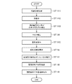
- FIG. 10 is a flowchart for explaining the operation of the awakening effort motion estimation device 1c according to the fourth embodiment.
- the awakening effort motion estimation device 1c repeats the operation shown in the flowchart of FIG. 10, for example, after the engine of the vehicle 3 is turned on until the engine is turned off.
- steps ST1111 to ST1112 and steps ST1114 to ST1119 are the same as the specific operations of steps ST1 to ST8 in FIG. Description is omitted.
- the hand detection unit 113 detects whether or not the driver's hand exists within the driver's face detection range based on the captured image acquired by the captured image acquisition unit 101 in step ST1111 (step ST1113).
- step ST1117 when hand detection section 113 detects that the driver's hand exists within the range where the driver's face is detected, motion estimation section 106 causes the driver to perform an awakening effort motion until the estimated stop time elapses. Do not estimate whether or not Since the motion estimating unit 106 does not output the awakening effort estimation result until the estimated stop time has elapsed, the reduced wakefulness state estimation unit 107 also estimates the driver's reduced wakefulness state until the estimated stop time has passed. do not have. The reduced alertness state information is not output from the output unit 108 until the estimated stop time has elapsed.
- the processing of steps ST1114 to ST1119 may not be performed until the estimated stop time has passed.
- the motion estimation unit 106 detects that the driver does not open his/her mouth until the estimated stop time elapses. It is sufficient that the estimation of whether or not the awakening effort motion is performed by moving is not performed.
- the processing is performed in the order of steps ST1112, ST1113, and ST114, but this is only an example, and the processing order of steps ST1112 to ST1114 does not matter.
- the processing of steps ST1112 to ST1114 may be performed in parallel.
- Embodiment 4 when awakening effort motion estimation apparatus 1c does not include face detection section 102 and mask detection section 103, the operations of above-described awakening effort motion estimation apparatus 1c are performed in steps ST1112 and ST1114. Can be omitted. Further, in Embodiment 4, when arousal effort motion estimation device 1c does not include arousal level-reduced state estimation section 107 and output section 108, the operation of above-described arousal effort motion estimation device 1c is performed in steps ST1118 and ST1119. Processing can be omitted.
- the awakening effort motion estimation device 1c estimates whether or not the driver is performing an awakening effort motion by moving the mouth, for example, when the driver performs a motion to correct the position of the mask by hand. discontinue temporarily.
- the awakening effort motion estimation device 1c can reduce erroneous estimation of the awakening effort motion due to the driver's mouth movement, and improve the estimation accuracy of the awakening effort motion.
- the awakening effort motion estimating device 1c considers the mask size of the occupant based on the captured image acquired from the camera 2, and controls to estimate whether or not the occupant performs an awakening effort motion by moving the mouth.
- a processing circuit 401 is provided for performing The processing circuit 401 reads out and executes programs stored in the memory 405 to obtain a captured image acquisition unit 101, a face detection unit 102, a mask detection unit 103, a reference point detection unit 104, and a distance calculation unit 105. , the functions of the motion estimation unit 106, the reduced wakefulness state estimation unit 107, the output unit 108, and the hand detection unit 113 are executed.
- the awakening effort motion estimation device 1b includes a memory 405 for storing a program that results in the execution of steps ST1111 to ST1119 in FIG. 10 when executed by the processing circuit 401.
- the programs stored in the memory 405 include the captured image acquisition unit 101, the face detection unit 102, the mask detection unit 103, the reference point detection unit 104, the distance calculation unit 105, the motion estimation unit 106, and the wakefulness detection unit 106. It can also be said that the procedure or method of the lowered degree state estimation unit 107, the output unit 108, and the hand detection unit 113 are executed by a computer.
- the arousal effort motion estimation device 1c includes a device such as the camera 2, an input interface device 402 and an output interface device 403 that perform wired or wireless communication.
- the awakening effort motion estimation device 1c is an in-vehicle device mounted in the vehicle 3, and the captured image acquisition unit 101, the face detection unit 102, the mask detection unit 103, and the reference point detection unit 104 , the distance calculation unit 105, the motion estimation unit 106, the low alertness state estimation unit 107, the output unit 108, and the hand detection unit 113 are included in the awakening effort motion estimation device 1c.
- the captured image acquiring unit 101 , the face detecting unit 102 , the mask detecting unit 103 , the reference point detecting unit 104 , the distance calculating unit 105 , the motion estimating unit 106 , and the alertness reduction state estimating unit 107 are not limited to these.
- part of the output unit 108 and the hand detection unit 113 are installed in an in-vehicle device of the vehicle, and the rest are installed in a server connected to the in-vehicle device via a network.
- the unit 108 and the hand detection unit 113 may all be provided in the server.
- the awakening effort motion estimation device 1c detects that the occupant's hand exists within the detection range of the occupant's face in the imaged image.
- the motion estimating unit 106 has a hand detecting unit 113 that detects whether or not the hand detecting unit 113 detects that the occupant's hand exists within the detection range of the occupant's face, the estimated stop time elapses. Until then, it is configured not to estimate whether or not the occupant is performing an awakening effort motion by moving the mouth. Therefore, the awakening effort motion estimating device 1c can reduce misestimation of the awakening effort motion due to the driver's mouth movement, and improve the estimation accuracy of the awakening effort motion.
- the awakening effort motion estimation device of the present disclosure can estimate that the passenger is performing an awakening effort motion by moving the mouth even if the passenger is wearing a mask.
- Awakening effort motion estimation device 2 camera, 3 vehicle, 101 captured image acquisition unit, 102 face detection unit, 103 mask detection unit, 104 reference point detection unit, 105 distance calculation unit, 106 motion estimation unit , 107 arousal level reduction state estimation unit, 108 output unit, 109 face orientation detection unit, 110 distance correction unit, 111 mask size detection unit, 112 adjustment unit, 113 hand detection unit, 401 processing circuit, 402 input interface device, 403 output Interface device, 404 processor, 405 memory.
Landscapes
- Engineering & Computer Science (AREA)
- Health & Medical Sciences (AREA)
- Life Sciences & Earth Sciences (AREA)
- Physics & Mathematics (AREA)
- General Physics & Mathematics (AREA)
- General Health & Medical Sciences (AREA)
- Theoretical Computer Science (AREA)
- Multimedia (AREA)
- Computer Vision & Pattern Recognition (AREA)
- Public Health (AREA)
- Veterinary Medicine (AREA)
- Animal Behavior & Ethology (AREA)
- Biophysics (AREA)
- Pathology (AREA)
- Biomedical Technology (AREA)
- Heart & Thoracic Surgery (AREA)
- Medical Informatics (AREA)
- Molecular Biology (AREA)
- Surgery (AREA)
- Psychiatry (AREA)
- Hospice & Palliative Care (AREA)
- Psychology (AREA)
- Social Psychology (AREA)
- Educational Technology (AREA)
- Developmental Disabilities (AREA)
- Child & Adolescent Psychology (AREA)
- Oral & Maxillofacial Surgery (AREA)
- Human Computer Interaction (AREA)
- Nuclear Medicine, Radiotherapy & Molecular Imaging (AREA)
- Radiology & Medical Imaging (AREA)
- Physiology (AREA)
- Dentistry (AREA)
- Traffic Control Systems (AREA)
- Measurement Of The Respiration, Hearing Ability, Form, And Blood Characteristics Of Living Organisms (AREA)
- Image Analysis (AREA)
Priority Applications (4)
| Application Number | Priority Date | Filing Date | Title |
|---|---|---|---|
| DE112021007459.8T DE112021007459T5 (de) | 2021-04-06 | 2021-04-06 | Aufwachbemühungsbewegungschätzvorrichtung und Aufwachbemühungsbewegungschätzverfahren |
| PCT/JP2021/014559 WO2022215145A1 (ja) | 2021-04-06 | 2021-04-06 | 覚醒努力動作推定装置および覚醒努力動作推定方法 |
| JP2023512535A JP7333883B2 (ja) | 2021-04-06 | 2021-04-06 | 覚醒努力動作推定装置および覚醒努力動作推定方法 |
| US18/277,411 US20240122513A1 (en) | 2021-04-06 | 2021-04-06 | Awakening effort motion estimation device and awakening effort motion estimation method |
Applications Claiming Priority (1)
| Application Number | Priority Date | Filing Date | Title |
|---|---|---|---|
| PCT/JP2021/014559 WO2022215145A1 (ja) | 2021-04-06 | 2021-04-06 | 覚醒努力動作推定装置および覚醒努力動作推定方法 |
Publications (1)
| Publication Number | Publication Date |
|---|---|
| WO2022215145A1 true WO2022215145A1 (ja) | 2022-10-13 |
Family
ID=83545222
Family Applications (1)
| Application Number | Title | Priority Date | Filing Date |
|---|---|---|---|
| PCT/JP2021/014559 Ceased WO2022215145A1 (ja) | 2021-04-06 | 2021-04-06 | 覚醒努力動作推定装置および覚醒努力動作推定方法 |
Country Status (4)
| Country | Link |
|---|---|
| US (1) | US20240122513A1 (https=) |
| JP (1) | JP7333883B2 (https=) |
| DE (1) | DE112021007459T5 (https=) |
| WO (1) | WO2022215145A1 (https=) |
Cited By (1)
| Publication number | Priority date | Publication date | Assignee | Title |
|---|---|---|---|---|
| US20240122513A1 (en) * | 2021-04-06 | 2024-04-18 | Mitsubishi Electric Corporation | Awakening effort motion estimation device and awakening effort motion estimation method |
Families Citing this family (1)
| Publication number | Priority date | Publication date | Assignee | Title |
|---|---|---|---|---|
| JP2024519297A (ja) * | 2021-04-30 | 2024-05-10 | ホアウェイ・テクノロジーズ・カンパニー・リミテッド | 表示調整方法及び装置 |
Citations (4)
| Publication number | Priority date | Publication date | Assignee | Title |
|---|---|---|---|---|
| JP2007229218A (ja) * | 2006-03-01 | 2007-09-13 | Toyota Motor Corp | 覚醒度推定装置及びシステム並びに方法 |
| JP2009265722A (ja) * | 2008-04-22 | 2009-11-12 | Calsonic Kansei Corp | 顔向き検知装置 |
| JP2010097379A (ja) * | 2008-10-16 | 2010-04-30 | Denso Corp | ドライバモニタリング装置およびドライバモニタリング装置用のプログラム |
| JP2018143285A (ja) * | 2017-03-01 | 2018-09-20 | 株式会社デンソーテン | 生体状態判定装置、生体状態判定システム、及び、生体状態判定方法 |
Family Cites Families (15)
| Publication number | Priority date | Publication date | Assignee | Title |
|---|---|---|---|---|
| JP5012690B2 (ja) * | 2008-06-24 | 2012-08-29 | トヨタ自動車株式会社 | 顔面の覆体及び顔面部位特定方法 |
| US11318949B2 (en) * | 2010-06-07 | 2022-05-03 | Affectiva, Inc. | In-vehicle drowsiness analysis using blink rate |
| JP7074432B2 (ja) * | 2017-06-26 | 2022-05-24 | 本田技研工業株式会社 | 車両制御システム、車両制御方法、および車両制御プログラム |
| JP6888542B2 (ja) | 2017-12-22 | 2021-06-16 | トヨタ自動車株式会社 | 眠気推定装置及び眠気推定方法 |
| JP7232008B2 (ja) * | 2018-09-27 | 2023-03-02 | 株式会社アイシン | 乗員モニタリング装置、乗員モニタリング方法、および乗員モニタリングプログラム |
| JP7380380B2 (ja) * | 2020-03-26 | 2023-11-15 | いすゞ自動車株式会社 | 運転支援装置 |
| US11565571B2 (en) * | 2020-12-08 | 2023-01-31 | Ford Global Technologies, Llc | Systems and methods to protect the health of occupants of a vehicle |
| JP7333883B2 (ja) * | 2021-04-06 | 2023-08-25 | 三菱電機株式会社 | 覚醒努力動作推定装置および覚醒努力動作推定方法 |
| US12477233B2 (en) * | 2021-04-23 | 2025-11-18 | Mitsubishi Electric Corporation | In-vehicle exposure control device and exposure control method |
| US12033656B2 (en) * | 2021-06-19 | 2024-07-09 | Kyndryl, Inc. | Diarisation augmented reality aide |
| US11945461B2 (en) * | 2021-08-05 | 2024-04-02 | Hyundai Mobis Co., Ltd. | System for preventing drunk driving and method for controlling the same |
| US11699282B1 (en) * | 2022-06-30 | 2023-07-11 | Plusai, Inc. | Data augmentation for vehicle control |
| US11574462B1 (en) * | 2022-06-30 | 2023-02-07 | Plus AI, Inc. | Data augmentation for detour path configuring |
| US11702011B1 (en) * | 2022-06-30 | 2023-07-18 | Plusai, Inc. | Data augmentation for driver monitoring |
| US20250022290A1 (en) * | 2023-07-10 | 2025-01-16 | Nvidia Corporation | Image-based three-dimensional occupant assessment for in-cabin monitoring systems and applications |
-
2021
- 2021-04-06 JP JP2023512535A patent/JP7333883B2/ja active Active
- 2021-04-06 WO PCT/JP2021/014559 patent/WO2022215145A1/ja not_active Ceased
- 2021-04-06 US US18/277,411 patent/US20240122513A1/en not_active Abandoned
- 2021-04-06 DE DE112021007459.8T patent/DE112021007459T5/de not_active Withdrawn
Patent Citations (4)
| Publication number | Priority date | Publication date | Assignee | Title |
|---|---|---|---|---|
| JP2007229218A (ja) * | 2006-03-01 | 2007-09-13 | Toyota Motor Corp | 覚醒度推定装置及びシステム並びに方法 |
| JP2009265722A (ja) * | 2008-04-22 | 2009-11-12 | Calsonic Kansei Corp | 顔向き検知装置 |
| JP2010097379A (ja) * | 2008-10-16 | 2010-04-30 | Denso Corp | ドライバモニタリング装置およびドライバモニタリング装置用のプログラム |
| JP2018143285A (ja) * | 2017-03-01 | 2018-09-20 | 株式会社デンソーテン | 生体状態判定装置、生体状態判定システム、及び、生体状態判定方法 |
Cited By (1)
| Publication number | Priority date | Publication date | Assignee | Title |
|---|---|---|---|---|
| US20240122513A1 (en) * | 2021-04-06 | 2024-04-18 | Mitsubishi Electric Corporation | Awakening effort motion estimation device and awakening effort motion estimation method |
Also Published As
| Publication number | Publication date |
|---|---|
| JP7333883B2 (ja) | 2023-08-25 |
| DE112021007459T5 (de) | 2024-03-14 |
| US20240122513A1 (en) | 2024-04-18 |
| JPWO2022215145A1 (https=) | 2022-10-13 |
Similar Documents
| Publication | Publication Date | Title |
|---|---|---|
| JP5109922B2 (ja) | ドライバモニタリング装置およびドライバモニタリング装置用のプログラム | |
| JP6811834B2 (ja) | 運転状態判定装置および運転状態判定方法 | |
| CN106687037B (zh) | 用于检测瞬时睡眠的设备、方法和计算机程序 | |
| JP5177011B2 (ja) | 開眼度特定装置 | |
| CN106716515A (zh) | 驾驶员状态判定装置 | |
| JP7333883B2 (ja) | 覚醒努力動作推定装置および覚醒努力動作推定方法 | |
| US11161470B2 (en) | Occupant observation device | |
| JP6973928B2 (ja) | 瞼開閉判定装置および眠気検知装置 | |
| CN105765341B (zh) | 目视确认区域推断装置 | |
| JPWO2020161768A1 (ja) | 感情推定装置及び感情推定方法 | |
| JP7550879B2 (ja) | 睡眠検出装置及び睡眠検出システム | |
| CN107960989A (zh) | 脉搏波计测装置以及脉搏波计测方法 | |
| US12240469B2 (en) | Occupant state detection device and occupant state detection method | |
| US20230237848A1 (en) | System and method for characterizing droopy eyelid | |
| JP6747493B2 (ja) | ドライバ状態判定装置 | |
| CN114084145A (zh) | 车辆及其控制方法 | |
| US10970557B2 (en) | Posture determination method, electronic system and non-transitory computer-readable recording medium | |
| US20220117529A1 (en) | System and method for determining an eye movement | |
| JP2022012829A (ja) | ドライバモニタ装置及びドライバモニタ方法 | |
| JP7612118B2 (ja) | 眠気推定装置および眠気推定方法 | |
| US20240386729A1 (en) | Method and Monitoring Device for Determining an Eye State of a Person, and Motor Vehicle Equipped Therewith | |
| JP7091632B2 (ja) | 安全運転促進装置及び安全運転促進方法 | |
| JP2022100538A (ja) | 生体情報取得装置 | |
| JP7774767B2 (ja) | 眠気判定装置及び眠気判定方法 | |
| JP7731959B2 (ja) | 自動運転引継ぎ判定方法及びそのシステム |
Legal Events
| Date | Code | Title | Description |
|---|---|---|---|
| 121 | Ep: the epo has been informed by wipo that ep was designated in this application |
Ref document number: 21935953 Country of ref document: EP Kind code of ref document: A1 |
|
| ENP | Entry into the national phase |
Ref document number: 2023512535 Country of ref document: JP Kind code of ref document: A |
|
| WWE | Wipo information: entry into national phase |
Ref document number: 18277411 Country of ref document: US |
|
| WWE | Wipo information: entry into national phase |
Ref document number: 112021007459 Country of ref document: DE |
|
| 122 | Ep: pct application non-entry in european phase |
Ref document number: 21935953 Country of ref document: EP Kind code of ref document: A1 |