WO2022211110A1 - 照明装置、装着装置、及び画像形成装置 - Google Patents
照明装置、装着装置、及び画像形成装置 Download PDFInfo
- Publication number
- WO2022211110A1 WO2022211110A1 PCT/JP2022/016924 JP2022016924W WO2022211110A1 WO 2022211110 A1 WO2022211110 A1 WO 2022211110A1 JP 2022016924 W JP2022016924 W JP 2022016924W WO 2022211110 A1 WO2022211110 A1 WO 2022211110A1
- Authority
- WO
- WIPO (PCT)
- Prior art keywords
- reflecting
- lighting device
- light
- image forming
- reflecting surface
- Prior art date
- Legal status (The legal status is an assumption and is not a legal conclusion. Google has not performed a legal analysis and makes no representation as to the accuracy of the status listed.)
- Ceased
Links
Images





Classifications
-
- F—MECHANICAL ENGINEERING; LIGHTING; HEATING; WEAPONS; BLASTING
- F21—LIGHTING
- F21V—FUNCTIONAL FEATURES OR DETAILS OF LIGHTING DEVICES OR SYSTEMS THEREOF; STRUCTURAL COMBINATIONS OF LIGHTING DEVICES WITH OTHER ARTICLES, NOT OTHERWISE PROVIDED FOR
- F21V33/00—Structural combinations of lighting devices with other articles, not otherwise provided for
-
- F—MECHANICAL ENGINEERING; LIGHTING; HEATING; WEAPONS; BLASTING
- F21—LIGHTING
- F21K—NON-ELECTRIC LIGHT SOURCES USING LUMINESCENCE; LIGHT SOURCES USING ELECTROCHEMILUMINESCENCE; LIGHT SOURCES USING CHARGES OF COMBUSTIBLE MATERIAL; LIGHT SOURCES USING SEMICONDUCTOR DEVICES AS LIGHT-GENERATING ELEMENTS; LIGHT SOURCES NOT OTHERWISE PROVIDED FOR
- F21K9/00—Light sources using semiconductor devices as light-generating elements, e.g. using light-emitting diodes [LED] or lasers
- F21K9/60—Optical arrangements integrated in the light source, e.g. for improving the colour rendering index or the light extraction
- F21K9/68—Details of reflectors forming part of the light source
-
- F—MECHANICAL ENGINEERING; LIGHTING; HEATING; WEAPONS; BLASTING
- F21—LIGHTING
- F21V—FUNCTIONAL FEATURES OR DETAILS OF LIGHTING DEVICES OR SYSTEMS THEREOF; STRUCTURAL COMBINATIONS OF LIGHTING DEVICES WITH OTHER ARTICLES, NOT OTHERWISE PROVIDED FOR
- F21V7/00—Reflectors for light sources
- F21V7/0025—Combination of two or more reflectors for a single light source
- F21V7/0033—Combination of two or more reflectors for a single light source with successive reflections from one reflector to the next or following
-
- F—MECHANICAL ENGINEERING; LIGHTING; HEATING; WEAPONS; BLASTING
- F21—LIGHTING
- F21V—FUNCTIONAL FEATURES OR DETAILS OF LIGHTING DEVICES OR SYSTEMS THEREOF; STRUCTURAL COMBINATIONS OF LIGHTING DEVICES WITH OTHER ARTICLES, NOT OTHERWISE PROVIDED FOR
- F21V7/00—Reflectors for light sources
- F21V7/04—Optical design
- F21V7/09—Optical design with a combination of different curvatures
-
- F—MECHANICAL ENGINEERING; LIGHTING; HEATING; WEAPONS; BLASTING
- F21—LIGHTING
- F21V—FUNCTIONAL FEATURES OR DETAILS OF LIGHTING DEVICES OR SYSTEMS THEREOF; STRUCTURAL COMBINATIONS OF LIGHTING DEVICES WITH OTHER ARTICLES, NOT OTHERWISE PROVIDED FOR
- F21V7/00—Reflectors for light sources
- F21V7/0025—Combination of two or more reflectors for a single light source
-
- F—MECHANICAL ENGINEERING; LIGHTING; HEATING; WEAPONS; BLASTING
- F21—LIGHTING
- F21V—FUNCTIONAL FEATURES OR DETAILS OF LIGHTING DEVICES OR SYSTEMS THEREOF; STRUCTURAL COMBINATIONS OF LIGHTING DEVICES WITH OTHER ARTICLES, NOT OTHERWISE PROVIDED FOR
- F21V7/00—Reflectors for light sources
- F21V7/04—Optical design
- F21V7/041—Optical design with conical or pyramidal surface
-
- F—MECHANICAL ENGINEERING; LIGHTING; HEATING; WEAPONS; BLASTING
- F21—LIGHTING
- F21Y—INDEXING SCHEME ASSOCIATED WITH SUBCLASSES F21K, F21L, F21S and F21V, RELATING TO THE FORM OR THE KIND OF THE LIGHT SOURCES OR OF THE COLOUR OF THE LIGHT EMITTED
- F21Y2103/00—Elongate light sources, e.g. fluorescent tubes
- F21Y2103/30—Elongate light sources, e.g. fluorescent tubes curved
- F21Y2103/33—Elongate light sources, e.g. fluorescent tubes curved annular
-
- F—MECHANICAL ENGINEERING; LIGHTING; HEATING; WEAPONS; BLASTING
- F21—LIGHTING
- F21Y—INDEXING SCHEME ASSOCIATED WITH SUBCLASSES F21K, F21L, F21S and F21V, RELATING TO THE FORM OR THE KIND OF THE LIGHT SOURCES OR OF THE COLOUR OF THE LIGHT EMITTED
- F21Y2115/00—Light-generating elements of semiconductor light sources
- F21Y2115/10—Light-emitting diodes [LED]
Definitions
- the technology of the present disclosure relates to lighting devices, mounting devices, and image forming devices.
- Japanese Patent Application Laid-Open No. 2008-216540 discloses a light-transmitting columnar body, a concave portion provided on one surface of the cylindrical body so as to accommodate the light source without contacting the light source, and the columnar body.
- a morning-glory reflecting surface having a morning-glory shape that is provided on the other surface and diffuses the incident light from the recess, and a morning-glory-shaped reflecting surface that is provided at the peripheral edge of the morning-glory-shaped reflecting surface and reflects the reflected light from the morning-glory-shaped reflecting surface.
- an inclined reflective surface that transmits light and a planar reflective surface that is provided on one surface of the cylindrical body excluding the recess and reflects the reflected light from the morning glory-shaped reflective surface and the inclined reflective surface.
- a featured light redirecting element is disclosed.
- the lighting device includes a light source arranged on one surface, a first direction side along the one surface, and a second direction perpendicular to the first direction along the one surface. and a reflective portion that reflects light in two directions. Since the lighting device has only a single reflecting portion, it is difficult to lengthen the area illuminated with the light directed in the first direction along the second direction.
- One embodiment according to the technology of the present disclosure is a lighting device and a mounting device that can elongate a region illuminated with light directed in the first direction along the second direction compared to a configuration having only a single reflecting portion. and an image forming apparatus.
- a lighting device includes a light source arranged on one surface, a first direction side that is one direction along the one surface, and light from the light source along the one surface and in the first direction. a first reflecting portion that reflects light to a second direction side perpendicular to the first reflecting portion; and two reflectors.
- the technology of the present disclosure compared to a configuration having only a single reflecting portion (that is, the first reflecting portion), it is possible to lengthen the region illuminated with the light traveling in the first direction along the second direction.
- FIG. 1 is a perspective view showing an image forming apparatus according to an embodiment
- FIG. FIG. 2 is a perspective view showing the image forming apparatus according to the exemplary embodiment viewed from the rear side; 2 is a left side view showing part of the image forming apparatus according to the embodiment;
- FIG. It is a perspective view which shows the illuminating device which concerns on this embodiment. It is a perspective view which shows the illuminating device (part except a cover) which concerns on this embodiment. It is a front view which shows the illuminating device (part except a cover) which concerns on this embodiment. It is a plane sectional view showing the lighting installation concerning this embodiment.
- FIG. 4 is a cross-sectional plan view showing the path of reflected light in the lighting device according to the embodiment; It is a perspective view showing a substrate and a light-emitting element in the lighting device according to the present embodiment.
- FIG. 3 is a perspective view showing a first reflector and light-emitting elements in the lighting device according to the embodiment; It is a block diagram which shows an example of the hardware constitutions of the control apparatus which concerns on this embodiment. It is a block diagram showing an example of functional composition of a processor of a control device concerning this embodiment.
- FIG. 4 is a cross-sectional plan view for comparing a configuration in which the curvature of the reflecting surface of the second reflector decreases toward the left side and a configuration in which the curvature increases toward the left side in the lighting device according to the present embodiment.
- FIG. 4 is a front view showing a configuration in which the corners of the second reflector are rounded in the lighting device according to the embodiment;
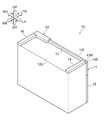
- FIG. 1 is a perspective view showing an image forming apparatus 10.
- FIG. 2 is a perspective view showing the image forming apparatus 10 viewed from the rear side.
- the arrow UP shown in the figure indicates the upper side (vertically upward) of the device, and the arrow DO indicates the lower side (vertically downward) of the device.
- An arrow LH shown in the drawing indicates the left side of the device, and an arrow RH indicates the right side of the device.
- An arrow FR shown in the drawing indicates the front of the device, and an arrow RR indicates the rear of the device. Since these directions are defined for convenience of explanation, the configuration of the apparatus is not limited to these directions. Note that the word “device” may be omitted in each direction of the device. That is, for example, "above the device” may simply be indicated as “above.”
- vertical direction may be used to mean “both upward and downward” or “either upward or downward”.
- angle-to-left may be used to mean “both right and left” or “either right or left.”
- horizontal direction can also be said to be the lateral direction or the horizontal direction.
- anterior-posterior may be used to mean “both forward and rearward” or “either forward or rearward.”
- front-rear direction can also be said to be the lateral direction or the horizontal direction.
- up-down direction, the left-right direction, and the front-rear direction are directions that intersect each other (more specifically, orthogonal directions).
- the symbol with an “X” in the “ ⁇ ” in the figure means an arrow pointing from the front to the back of the paper.
- the symbol “ ⁇ ” written in the “o” in the drawing means an arrow pointing from the back to the front of the paper surface.
- the image forming apparatus 10 shown in FIGS. 1 and 2 is an image forming apparatus. Specifically, as shown in FIGS. 1 and 2, the image forming apparatus 10 includes an image forming apparatus main body 11, an illumination device 20, and an image forming section 18 (see FIG. 11).
- the image forming apparatus 10 is an example of a "mounting device". Each part of the image forming apparatus 10 will be described below.
- An image forming apparatus main body 11 shown in FIGS. 1 and 2 is a portion in which each component of the image forming apparatus 10 is provided.
- the image forming apparatus main body 11 is formed in a substantially rectangular parallelepiped shape, as shown in FIGS. 1 and 2 .
- a lighting device 20 is attached to the front side and right side portion of the upper portion of the image forming apparatus main body 11 (specifically, the upper surface 12U of the housing 12, which will be described later). Therefore, the lighting device 20 can be visually recognized from the front side and the right side of the image forming apparatus main body 11 .
- the image forming apparatus main body 11 specifically has a housing 12 and projecting portions 13 , 14 and 15 .
- the housing 12 is formed in a rectangular parallelepiped shape.
- the projecting portion 13 is arranged on the front side of the upper surface 12 ⁇ /b>U of the housing 12 and on the left side with respect to the lighting device 20 .
- the protruding portion 13 protrudes upward from the upper surface 12U of the housing 12 and extends in the left-right direction.
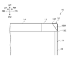
- the projecting portion 13 has a front end portion 13F on the upper edge located on the rear side of the front end portion 13E on the lower edge. Therefore, as shown in FIG. 3, the front surface 13M of the protruding portion 13 is formed as an inclined surface that slopes down gradually toward the front in a side view.
- the illumination device 20 protrudes forward from the front surface 13 ⁇ /b>M of the protruding portion 13 so that the illumination device 20 can be visually recognized from the left side of the image forming apparatus main body 11 .
- a side view refers to a case where the object (here, the projecting portion 13) is viewed from one of the left and right sides of the object (here, the projecting portion 13) toward the other.
- the projecting portion 14 is arranged on the left side of the upper surface 12U of the housing 12 and on the rear side with respect to the projecting portion 13, as shown in FIGS.
- the protruding portion 14 protrudes upward from the upper surface 12U of the housing 12 and extends in the front-rear direction.
- the projecting portion 15 is arranged on the right side of the upper surface 12U of the housing 12 and on the rear side with respect to the lighting device 20 .
- the protruding portion 15 protrudes upward from the upper surface 12U of the housing 12 and extends in the front-rear direction.
- the image forming apparatus main body 11 is open on the left side with respect to the projecting portion 15 and on the rear side with respect to the illumination device 20 . Therefore, the illumination device 20 can be visually recognized from the rear side of the image forming apparatus main body 11 .
- the image forming apparatus main body 11 is an example of a "mounting body”.
- the protruding portion 13 is an example of the “arranged portion”.
- An image forming unit 18 shown in FIG. 11 is an example of an image forming unit that forms an image on a recording medium.
- Examples of the image forming unit 18 include an inkjet image forming unit that forms an image on a recording medium using ink, and an electrophotographic image forming unit that forms an image on a recording medium using toner. be done.
- an image is formed on a recording medium by ejecting ink droplets from an ejection unit onto the recording medium.
- the ink-jet image forming unit may form an image on a recording medium by ejecting ink droplets from an ejection unit onto a transfer body and transferring the ink droplets from the transfer body to the recording medium.
- each step of charging, exposure, development, and transfer is performed to form an image on a recording medium.
- each step of charging, exposure, development, and transfer is performed to form an image on a transfer body, and by transferring the image from the transfer body to a recording medium, an image is formed on the recording medium. may be formed.
- Examples of the image forming unit are not limited to the ink jet image forming unit and the electrophotographic image forming unit described above, and various image forming units can be used.
- FIG. 4 is a perspective view showing the illumination device 20.
- FIG. FIG. 5 is a perspective view showing the illumination device 20 (a portion excluding a cover 70 which will be described later).
- FIG. 6 is a front view showing the illumination device 20 (a portion excluding a cover 70 which will be described later).
- FIG. 7 is a plan sectional view showing lighting device 20.
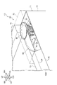
- FIG. 8 is a cross-sectional plan view showing the path of reflected light in lighting device 20.
- FIG. 9 is a perspective view showing a substrate 40 and light-emitting elements 28 in the illumination device 20, which will be described later.
- FIG. 10 is a perspective view showing a first reflecting plate 50 and a light emitting element 28 in the illumination device 20, which will be described later.
- the lighting device 20 shown in FIGS. 4 to 8 is a device that illuminates its surroundings. Specifically, as shown in FIG. 4, the lighting device 20 includes a base 30, a substrate 40, a light emitting element 28, a first reflector 50, a second reflector 60, and a cover 70. I have.
- the platform 30 is a portion on which each component of the lighting device 20 is arranged, as shown in FIGS.
- the table 30 has a plate-like shape with a thickness direction extending in the vertical direction, and is formed in a rectangular shape elongated in the horizontal direction in a plan view.
- a substrate 40 is arranged on the right side portion of the upper surface 32 of the table 30 .
- a left portion of the upper surface 32 of the base 30 with respect to the substrate 40 is a reflecting surface 33 that reflects the light from the light emitting element 28 .
- the base 30 is made of, for example, a resin material, and the upper surface 32 including the reflecting surface 33 is made of, for example, a white surface.
- the upper surface 32 including the reflecting surface 33 may be, for example, a plated surface as long as it reflects light.
- the substrate 40 is, for example, formed in a rectangular plate shape whose thickness direction is in the vertical direction.
- the substrate 40 is configured by a printed circuit board, for example.
- Substrate 40 has a top surface 42 that faces upward. This upper surface 42 is specifically a horizontal surface along the horizontal direction.
- the light-emitting element 28 is, for example, an LED (light emitting diode) element.
- a plurality of light emitting elements 28 are arranged in an elliptical shape on the upper surface 42 of the substrate 40 .
- the plurality of light emitting elements 28 are arranged on the front side, the rear side, the left side, and the right side with respect to the first reflector 50 in plan view.
- the plurality of light emitting elements 28 are arranged one on each of the front and rear sides of the first reflector 50, and one on each of the left and right sides of the first reflector 50.
- planar view means the case where the object (here, the light emitting element 28) is viewed downward from above the object.
- the light emitting element 28 irradiates light with a spread on the upper side (see FIG. 10).
- the light emitting element 28 may be a light source that irradiates at least the first reflecting plate 50 with light.
- the light emitting element 28 can selectively emit light in a plurality of colors (for example, blue and red).
- the first reflector 50 has a function of reflecting the light from the light emitting element 28 forward, backward, left, and right.
- the first reflector 50 is arranged on the upper surface 42 of the substrate 40, as shown in FIGS.
- the first reflector 50 is made of a resin material, for example, and has a white surface, for example.
- the surface of the first reflecting plate 50 may be, for example, a plated surface as long as it reflects light.
- the first reflecting plate 50 has an elliptical shape with its major axis extending in the left-right direction in a plan view, and the top-bottom direction as illustrated in FIGS. It is formed in a cylindrical shape with an axial direction.
- the first reflecting plate 50 has a curved portion 51 that curves upward from the substrate 40 so as to gradually increase in diameter toward the outer peripheral side, and an upper portion that extends upward from the upper end of the curved portion 51 . 52 and .
- the outer peripheral surface of the curved portion 51 is curved in a curved shape toward the left side and the right side as it goes upward when viewed from the rear, and is curved to be convex inward.
- the first reflecting plate 50 has reflecting surfaces 57 and 59 that curve toward the left side and the right side as it goes upward when viewed from behind.
- the backward view refers to the case where the object (here, the first reflector 50) is viewed from the front to the rear.
- a protruding portion 53 protrudes radially outward and is formed along the entire circumference along its own circumferential direction.
- a protruding portion 55 that protrudes outward and is formed along the vertical direction from the lower end to the upper end of the curved portion 51 is formed.
- a plurality of projecting portions 53 are arranged along the vertical direction.
- the width of the projecting portion 55 along the circumferential direction of the curved portion 51 gradually widens from the lower end to the upper end of the curved portion 51 .
- a plurality of projecting portions 55 are arranged along the circumferential direction of the curved portion 51 and intersect the projecting portions 53 . In this manner, the projecting portions 53 and 55 intersect each other, so that the projecting portions 53 and 55 are arranged in a grid pattern around the outer periphery of the curved portion 51 .
- the upper portion 52 is formed in an elliptical cylindrical shape linearly extending upward from the upper end of the curved portion 51 .
- the outer peripheral surface of the upper portion 52 is an elliptical cylindrical surface without irregularities.
- the curved portion 51 and the overhanging portions 53 and 55 transmit the light from the light emitting element 28 to the front side, the rear side, the left side, and the right side. It is diffusely reflected in 360-degree directions (see FIG. 10).
- the upper part 52 of the first reflector 50 also reflects the light from the light emitting element 28 in 360-degree directions including the front side, the rear side, the left side, and the right side.
- the second reflector 60 is arranged on the left side with respect to the first reflector 50, as shown in FIGS. 5 to 8. As shown in FIG. It has the function of reflecting to As with the first reflector 50, the second reflector 60 is made of a resin material, for example, and has a white surface, for example. The surface of the second reflector 60 may be plated, for example, as long as it reflects light.
- the second reflector 60 includes an extending portion 61 extending upward from the upper surface 32 of the table 30, a facing portion 62 facing the upper surface 32 of the table 30, A connecting portion 66 that connects the extending portion 61 and the facing portion 62 is provided.
- the extending portion 61 has a reflecting surface 63 that faces forward and curves forward in a concave shape.
- the extending portion 61 is formed in a plate shape having a thickness direction that intersects the reflecting surface 63 . The curvature of the reflecting surface 63 decreases toward the left side.
- the facing portion 62 has a reflective surface 64 that faces the upper surface of the table 30 while being spaced apart from it and faces downward.
- the facing portion 62 is formed in a plate shape having a thickness direction that intersects the reflecting surface 64 .
- the facing portion 62 has a rear end portion 62B curved forward along the extending portion 61 in a concave shape, and the width in the front-rear direction gradually narrows from the right side to the left side.
- a right end portion of the facing portion 62 is curved in a concave shape along a portion of the upper portion 52 of the first reflector 50 in the circumferential direction.
- the connecting portion 66 connects the rear end portion of the facing portion 62 and the upper end portion of the extending portion 61, and the extending portion 61, the facing portion 62 and the connecting portion 66 are integrally connected. It is configured.
- the right end portion 63R of the reflecting surface 63 of the second reflecting plate 60 is arranged on the right side of the left end portion 50L of the first reflecting plate 50, as shown in FIGS. That is, as shown in FIG. 6, the right side portion of the reflecting surface 63 of the second reflecting plate 60 overlaps the left side portion of the first reflecting plate 50 when viewed from the rear. Further, the right end portion 63R of the reflecting surface 63 is arranged on the left side of the lower end portion 57D of the reflecting surface 57. As shown in FIG.
- the reflecting surface 64 of the second reflecting plate 60 is arranged above the upper end portion 57U of the reflecting surface 57 of the first reflecting plate 50 . Specifically, the reflecting surface 64 of the second reflecting plate 60 is arranged within the range from the lower end to the upper end of the upper portion 52 of the first reflecting plate 50 . In this embodiment, the upper surface of the facing portion 62 of the second reflector 60 and the upper surface of the first reflector 50 are arranged on the same plane.
- the reflecting surface 63 of the second reflecting plate 60 has a left end portion 63L facing rightward when viewed from the rear, and the left end portion 63L is a reflecting surface extending downward from the left end portion of the reflecting surface 64.
- a sharp corner portion 67 is formed by the reflecting surface 64 and the left end portion 63L of the reflecting surface 63 . Since the left end portion 63L of the reflecting surface 63 is also the front end portion of the reflecting surface 63, it can also be said to be the front end portion of the reflecting surface 63. As shown in FIG. In addition, when the radius of curvature of the inner peripheral surface of the corner portion 67 is equal to or less than the thickness of the second reflector 60, the corner portion 67 is angular. Therefore, when the radius of curvature of the inner peripheral surface of the corner 67 exceeds the thickness of the second reflector 60, the corner is rounded.
- An opening 69 surrounded by the front end portion 62F of the facing portion 62 of the second reflecting plate 60, the front end portion 61F of the extending portion 61, and the reflecting surface 33 of the base 30 is formed on the front side of the reflecting surface 63. It is Light reflected by the reflecting surfaces 63 and 64 of the second reflecting plate 60 and the reflecting surface 33 of the base 30 is emitted from the opening 69 .
- the front end portion 62F of the facing portion 62 and the front end portion 61F of the extending portion 61 are also the front end portion of the second reflector 60, and therefore can be said to be the front end portion of the second reflector 60. .
- the front end portion of the second reflector 60 (that is, the front end 62F of the facing portion 62 and the front end 61F of the extension portion 61) is arranged on the rear side with respect to the front end portion 50F of the. That is, the first reflector 50 protrudes further forward than the second reflector 60 .
- the second reflector 60 reflects forward part of the light reflected leftward from the first reflector 50 and reflects the other part of the light leftward, as shown in FIG. pass through to In other words, the second reflector 60 does not block the other part of the light.
- the second reflector 60 does not block the light reflected from the first reflector 50 to the rear side and the right side, and allows the light to be emitted to the outside of the illumination device 20 .
- the front end portion 50F of the first reflector 50 is arranged forward of the front end portion 13F of the upper edge of the projecting portion 13.
- the front end portion of the second reflector 60 that is, the front end portion 62F of the facing portion 62 and the front end portion 61F of the extension portion 61
- the front end portion of the second reflector 60 is located at the same position as the front end portion 13F on the upper edge of the projecting portion 13 in the front-rear direction. are placed in
- the cover 70 is arranged on the front side, the rear side, the left side, the right side, and the upper side with respect to the first reflector 50 and the second reflector 60, Cover these directions.
- the cover 70 is made of, for example, a transparent resin material, and is capable of transmitting light such as reflected light from the first reflector 50 and the second reflector 60 .
- the first reflector 50 and the second reflector 60 reflect the light from the light emitting element 28, so that the position where the first reflector 50 is arranged in the left-right direction , illuminates the front side so that it is the brightest and gradually gets darker toward the left side. That is, the illumination device 20 illuminates with gradation.
- the state having gradation is a state in which the brightness has brightness and the brightness changes continuously.
- the upper surface 42 of the substrate 40 is an example of "one surface”.
- the light emitting element 28 is an example of a "light source”.
- the first reflector 50 is an example of a "first reflector”.
- the second reflector 60 is an example of a "second reflector”.
- the forward direction is one direction along the upper surface 42 of the substrate 40 and is an example of the "first direction".
- the direction facing the front side is an example of the "first direction.”
- the leftward direction is a direction that extends along one plane and intersects the front, and is an example of a "second direction.”
- the leftward direction is an example of the "second direction.”
- Backward is an example of "a direction opposite to the first direction.”
- the right direction is an example of "a direction opposite to the second direction”.
- the upward direction is an example of "a separation direction that intersects a plane and separates from the plane.”
- the downward direction is an example of "a direction opposite to the separation direction.”
- the reflecting surface 63 of the second reflecting plate 60 is an example of a "reflecting surface facing the first direction” and an example of a “reflecting surface facing the first direction and curved concavely in the first direction". Note that the reflecting surface 63 faces forward (an example of the first direction) except for the left end portion 63L. Therefore, the "reflective surface facing the first direction” may include a portion facing a direction other than the first direction. Also, the “reflecting surface facing the first direction” is a reflective surface that can be visually recognized as a surface when viewed in the direction opposite to the first direction.
- the “reflecting surface facing the first direction” is specifically a surface that reflects light from the second direction toward the first direction, and is a surface that is not orthogonal to the first direction (i.e., the first direction). surface inclined with respect to one direction).
- the right end of the reflective surface 63 is an example of "the first end on the side opposite to the second direction”.
- the left end of the first reflector 50 is an example of the "second end on the second direction side”.
- the reflective surface 57 of the first reflective plate 50 is an example of "a reflective surface or a first reflective surface that inclines toward the second direction toward the separation direction".
- the lower end of the reflective surface 57 is an example of the "one side end”.
- the reflective surface 64 of the second reflective plate 60 is an example of "a reflective surface or a second reflective surface facing the side opposite to the separation direction".
- the reflective surface 63 is an example of "a reflective surface extending in the opposite direction from the end in the second direction of the reflective surface” at the left end 63L.
- the front end is an example of "the end in the first direction”.
- control device 90 has a control function of changing the lighting state of the lighting device 20 according to the operating state of the image forming apparatus 10 . Specifically, the control device 90 changes the lighting state of the lighting device 20 between an execution state in which the image forming section 18 is performing an image forming operation and a stop state in which the image forming section 18 is abnormally stopped. to control.
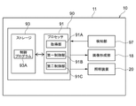
- control device 90 has a processor 91, a memory 92, and a storage 93, as shown in FIG.
- the control device 90 may be a device that controls the operation of each section of the image forming apparatus 10 including the image forming section 18 and the lighting device 20 .
- a processor refers to a processor in a broad sense, and the processor 91 includes a general-purpose processor (eg, CPU (Central Processing Unit)) and a dedicated processor (eg, GPU: Graphics Processing Unit, ASIC: Application Specific Integrated Circuit, FPGA: Field Programmable Gate Array, programmable logic device, etc.) are used.
- a general-purpose processor eg, CPU (Central Processing Unit)
- a dedicated processor eg, GPU: Graphics Processing Unit
- ASIC Application Specific Integrated Circuit
- FPGA Field Programmable Gate Array, programmable logic device, etc.
- the storage 93 stores various programs including a control program 93A (see FIG. 15) and various data.
- the storage 93 is specifically implemented by a recording device such as a HDD (Hard Disk Drive), an SSD (Solid State Drive), and a flash memory.
- the memory 92 is a work area for the processor 91 to execute various programs, and temporarily records various programs or various data when the processor 91 executes processing.
- the processor 91 reads various programs including the control program 93A from the storage 93 to the memory 92 and executes the programs using the memory 92 as a work area.
- FIG. 12 is a block diagram showing the functional configuration of the processor 91. As shown in FIG.
- the processor 91 functions as an acquisition section 91A, a first control section 91B, and a second control section 91C by executing a control program 93A.
- the acquisition unit 91A acquires an execution instruction to cause the image forming unit 18 to perform an image forming operation for forming an image on a recording medium. Further, the acquisition unit 91A detects a state in which the image forming unit 18 cannot be operated due to clogging of the recording medium, out of ink, out of toner, etc., based on the detection result of the detection unit 97 such as a sensor arranged in the image forming apparatus main body 11. Acquires drivable information indicating that the vehicle is inoperable.
- the first control unit 91B instructs the image forming unit 18 to perform the image forming operation when the acquisition unit 91A acquires an execution instruction to execute the image forming operation, and if the above-described operation-impossible information is not acquired. Control the execution.
- the first control unit 91B causes the image forming unit 18 to abnormally stop when the acquisition unit 91A acquires the above-described operation-impossible information when the acquisition unit 91A acquires an execution instruction for executing an image forming operation. It controls the image forming section 18 . Further, after the first control unit 91B controls the image forming unit 18 to execute the image forming operation, before the image forming operation in the image forming unit 18 is completed, the acquiring unit 91A performs the above-described When the operation-impossible information is acquired, the image forming unit 18 is controlled to abnormally stop.
- the second control unit 91C controls the illumination device 20 in the first illumination state when the above-described operation-impossible information is not acquired. Control lighting.
- the second control unit 91C instructs the lighting device 20 to perform the first Control is performed to illuminate in a second lighting state different from the lighting state.
- the first control unit 91B controls the image forming unit 18 to execute the image forming operation
- the second control unit 91C controls the image forming unit 18 to perform the image forming operation.
- the acquisition unit 91A acquires the above-described drivable information, it controls the lighting device 20 to illuminate in the second lighting state.
- the first lighting state is, for example, a state in which the lighting device 20 emits blue light by causing the light emitting element 28 to emit blue light.
- the second lighting state is, for example, a state in which the lighting device 20 emits red light by causing the light emitting element 28 to emit red light.
- the lighting device 20 functions as a display device that indicates the operating state of the image forming apparatus 10 .
- control device 90 may change the lighting state of the lighting device 20 to three or more states. Also, the control device 90 may change the lighting state of the lighting device 20 not only by the color but also by lighting and blinking. Further, the control device 90 may change the lighting state of the lighting device 20 including a normally stopped state and a resting state as the operating state of the image forming apparatus 10 .
- the second reflector 60 is arranged on the left side of the first reflector 50 as shown in FIGS. 1 Reflects the light from the reflecting plate 50 forward. Therefore, compared to the configuration in which the illumination device 20 has only the first reflector 50, the area illuminated with the forward light can be elongated in the left-right direction.
- the second reflector 60 is used for reflection, so that gradation can be applied in the horizontal direction in the illumination area of the lighting device 20 without increasing the number of light emitting elements 28 . becomes.
- the right end portion 63R of the reflecting surface 63 of the second reflecting plate 60 is arranged on the right side of the left end portion 50L of the first reflecting plate 50, as shown in FIGS. ing. Therefore, compared to the configuration in which the right end portion 63R of the reflecting surface 63 is arranged on the left side of the left end portion 50L of the first reflecting plate 50, the area illuminated by the reflected light of the first reflecting plate 50 and the second A reduction in the amount of light at the boundary between the area illuminated by the reflected light from the second reflector 60 and the area illuminated by the reflected light is suppressed.
- the right end portion 63R of the reflecting surface 63 is arranged on the left side of the lower end portion 57D of the reflecting surface 57. For this reason, compared to the configuration in which the right end portion 63R of the reflecting surface 63 is arranged on the right side of the lower end portion 57D of the reflecting surface 57, the region illuminated by the reflected light of the first reflecting plate 50 and the second reflecting light An area illuminated by the reflected light of the plate 60 and an area where the area overlaps are suppressed from having an excessive amount of light.
- the reflecting surface 64 of the second reflecting plate 60 is arranged above the upper end portion 57U of the reflecting surface 57 of the first reflecting plate 50 . For this reason, compared with the configuration in which the reflecting surface 64 of the second reflecting plate 60 is arranged below the upper end portion 57U of the reflecting surface 57 of the first reflecting plate 50, the upper end portion of the illumination area of the lighting device 20 is suppressed.
- the curvature of the reflecting surface 63 of the second reflecting plate 60 decreases toward the left side.
- configuration A in a configuration in which the curvature of the reflecting surface 63 increases toward the left side (hereinafter referred to as configuration A), light is reflected forward by the reflecting surface 63.
- the component that goes diagonally to the left ie, the left side of the front surface of the lighting device 20
- the component that goes to the diagonally front side of the lighting device 20 that is, the right side of the front surface of the lighting device 20
- the curvature of the reflecting surface 63 of the second reflecting plate 60 decreases toward the left side.
- the component (see symbol LB) toward the diagonally forward right side ie, the right side of the front surface of the lighting device 20
- the component toward the diagonally forward side ie, the left side of the front surface of the lighting device 20. Therefore, compared to the configuration A, the decrease in the amount of light at the boundary between the area illuminated by the reflected light of the first reflector 50 and the area illuminated by the reflected light of the second reflector 60 is suppressed.
- the reflective surface 64 and the left end portion 63L of the reflective surface 63 form an angular corner portion 67 .
- the rounded corner 67 As shown in FIG. 14, in a configuration in which the corner 67 formed by the reflecting surface 64 and the left end 63L of the reflecting surface 63 is rounded (hereinafter referred to as configuration B), the rounded corner 67 The area of the opening 69 becomes smaller at the corners. That is, the opening 69 is made smaller by the area indicated by the dashed line XA in FIG. Therefore, the light emitted from the opening 69 is reduced at the corner portion.
- the reflective surface 64 and the left end 63L of the reflective surface 63 form the angular corner 67. is suppressed.
- the second reflector 60 reflects forward part of the light reflected leftward from the first reflector 50, and reflects the other part of the light. pass the part to the left. Therefore, the left side of the lighting device 20 is illuminated.
- the second reflector 60 does not block the light reflected from the first reflector 50 to the rear side and the right side, and allows the light to be emitted to the outside of the lighting device 20 . Therefore, the rear and right sides of the lighting device 20 are illuminated.
- the front end portion 50F of the first reflector 50 is arranged forward of the front end portion 13F at the upper edge of the overhanging portion 13 .
- the light emitted from the illumination device 20 to the left side is is suppressed from being shielded. Therefore, the light from the illumination device 20 can be visually recognized from the left side of the image forming apparatus 10 (specifically, the image forming apparatus main body 11).
- the front end portion of the second reflector 60 (that is, the front end portion 62F of the facing portion 62 and the front end portion 61F of the extension portion 61) is located at the front end of the upper edge of the projecting portion 13 in the front-rear direction. It is arranged at the same position as the portion 13F. For this reason, compared to the configuration in which the front end portion of the second reflecting plate 60 is arranged on the front side of the front end portion 13 ⁇ /b>F of the upper edge of the projecting portion 13 , the image forming apparatus 10 (specifically, the image forming apparatus The amount of light illuminating the left side of the main body 11) increases.
- control device 90 performs control to change the lighting state of the lighting device 20 according to the operating state of the image forming apparatus 10 . Therefore, by checking the illumination state of the illumination device 20, it is possible to grasp the operating state of the image forming apparatus 10. FIG.
- control device 90 changes the lighting state of the lighting device 20 between an execution state in which the image forming section 18 is performing an image forming operation and a stop state in which the image forming section 18 is abnormally stopped. to control. Therefore, by confirming the lighting state of the lighting device 20, it is possible to grasp whether the image forming apparatus 10 is in the running state or the stopped state.
- the light emitting element 28 is used as an example of the light source in this embodiment, the light source is not limited to this.
- An example of the light source may be a lamp such as a fluorescent lamp, as long as it emits light.
- an LED element is used as an example of the light emitting element 28, but it is not limited to this.
- An example of the light emitting element 28 may be an organic EL (electro-luminescence) element as long as it emits light.
- the present invention is not limited to this.
- An example of "one side” may be, for example, a side facing downward, leftward, rightward, forward, or backward, and the direction in which the plane faces is not limited.
- the member on which one surface is formed is not limited to the substrate 40, and may be any member on which the light source is arranged.
- first direction is forward
- first direction may be, for example, upward, downward, leftward, rightward, or backward. If the first direction is one direction along one surface, There are no restrictions on the orientation of the first direction.
- the "second direction" is leftward
- An example of the "second direction” may be, for example, upward, downward, rightward, forward, or backward directions, and the second direction may be along one surface and intersect the first direction. There is no restriction on the orientation of the second direction as long as it is the direction to
- the first reflecting plate 50 as an example of the first reflecting portion has a function of reflecting the light from the light emitting element 28 to the front side, the rear side, the left side, and the right side.
- the first reflecting section for example, the light from the light source may be reflected forward, backward, and leftward, or reflected forward, leftward, and rightward. Any configuration may be used as long as the configuration reflects at least forward and leftward.
- the first reflecting portion there is no limitation on the shape, material, etc. as long as it has a function of reflecting light from the light source at least in the first direction and the second direction. .
- the second reflecting plate 60 as an example of the second reflecting portion has the extending portion 61 and the facing portion 62, but is not limited to this.
- the second reflecting portion there is no limitation on the shape, material, etc., as long as it has the function of reflecting the light from the first reflecting portion in the first direction.
- the right end portion 63R of the reflecting surface 63 of the second reflecting plate 60 is arranged on the right side of the left end portion 50L of the first reflecting plate 50, as shown in FIGS.
- the right end portion 63R of the reflecting surface 63 may be arranged on the left side of the left end portion 50L of the first reflecting plate 50 .
- the right end portion 63R of the reflecting surface 63 is arranged on the left side of the lower end portion 57D of the reflecting surface 57, but this is not the only option.
- the right end portion 63 ⁇ /b>R of the reflecting surface 63 may be arranged on the right side of the lower end portion 57 ⁇ /b>D of the reflecting surface 57 .
- the reflecting surface 64 of the second reflecting plate 60 is arranged above the upper end portion 57U of the reflecting surface 57 of the first reflecting plate 50, but this is not the only option.
- the reflecting surface 64 of the second reflecting plate 60 may be arranged below the upper end portion 57U of the reflecting surface 57 of the first reflecting plate 50 .
- the curvature of the reflecting surface 63 of the second reflecting plate 60 decreases toward the left side, but this is not the only option.
- the curvature of the reflecting surface 63 may increase toward the left side.
- the reflective surface 64 and the left end 63L of the reflective surface 63 form the angular corner 67, but this is not the only option.
- a configuration in which a corner portion 67 formed by the reflecting surface 64 and the left end portion 63L of the reflecting surface 63 is rounded may be employed.
- the front end portion 50F of the first reflecting plate 50 is arranged on the front side of the front end portion 13F at the upper edge of the projecting portion 13, but this is not the only option.
- the front end portion 50 ⁇ /b>F of the first reflector 50 may be arranged on the rear side of the front end portion 13 ⁇ /b>F of the upper edge of the projecting portion 13 .
- the front end portion of the second reflector 60 (that is, the front end portion 62F of the facing portion 62 and the front end portion 61F of the extension portion 61) is located at the front end of the upper edge of the projecting portion 13 in the front-rear direction. Although it is arranged at the same position as the portion 13F, it is not limited to this.
- the front end portion of the second reflector 60 may be arranged on the rear side of the front end portion 13 ⁇ /b>F of the upper edge of the projecting portion 13 .
- the front end portion of the second reflector 60 may be arranged on the front side of the front end portion 13 ⁇ /b>F of the upper edge of the projecting portion 13 .
- the illumination device 20 functions as a display device that indicates the operating state of the image forming apparatus 10, but the present invention is not limited to this.
- the illumination device 20 may be used exclusively for the purpose of illuminating the surroundings of the image forming apparatus 10, and the application of the illumination device 20 is not limited.
- the image forming apparatus 10 is used as an example of the mounting device, but the mounting device is not limited to this.
- An example of the mounting device may be, for example, a manufacturing device for manufacturing various products, and various devices can be used.
- a first aspect includes a light source arranged on one surface, a first direction side that is one direction along the one surface, and a second direction along the one surface and orthogonal to the first direction. a first reflecting portion that reflects light in two directions; a second reflecting portion that is disposed on the second direction side with respect to the first reflecting portion and reflects light from the first reflecting portion in the first direction; Prepare.
- the second reflecting portion has a reflecting surface facing the first direction, and a first end of the reflecting surface on the side opposite to the second direction It is arranged on the opposite direction side of the second end of the one reflecting portion on the second direction side.
- the first reflecting portion intersects the one surface and moves toward the second direction as it goes in a separating direction that intersects the one surface and separates from the one surface when viewed in a direction opposite to the first direction. It has an inclined reflective surface, and the first end is located closer to the second direction than the end of the reflective surface of the first reflective portion on the one surface side.
- the first reflecting portion intersects the one surface and is separated from the one surface when viewed in a direction opposite to the first direction.
- the second reflecting section has a first reflecting surface that inclines toward the second direction toward the direction, the second reflecting portion has a second reflecting surface that faces the direction opposite to the separating direction, and the second reflecting surface is , is arranged on the separation direction side of the end of the first reflecting surface on the separation direction side.
- the second reflecting portion has a reflecting surface facing the first direction and curved concavely in the first direction, The curvature of the reflecting surface decreases toward the second direction side.
- the second reflecting portion has a space that intersects with the one surface and is spaced apart from the one surface in a direction opposite to the first direction.
- a sharp corner is formed by the reflective surface facing in the opposite direction to the direction and the reflective surface extending in the opposite direction from the end of the reflective surface in the second direction.
- the second reflecting portion redirects part of the light reflected in the second direction from the first reflecting portion to the first direction. and pass another portion of the light in the second direction.
- the first reflecting section reflects light from the plurality of light sources in a direction opposite to the first direction and in a direction opposite to the second direction. The light is reflected to at least one side in the opposite direction, and the second reflecting section allows the light reflected to the at least one side to exit the lighting device.
- a ninth aspect is the lighting device according to any one aspect of the first to eighth aspects, and a mounted body having an arrangement portion on which the lighting device is mounted and arranged on the second direction side with respect to the lighting device and, the end portion in the first direction of the first reflecting portion of the lighting device is arranged closer to the first direction side than the end portion of the arrangement portion in the first direction.
- the end portion in the first direction of the second reflecting portion of the lighting device is located at the same position in the first direction as the end portion of the arrangement portion in the first direction, Alternatively, it is arranged on the side opposite to the first direction from the end of the arrangement portion in the first direction.
- An eleventh aspect is a mounting device to which the lighting device according to any one of the first to eighth aspects is mounted, wherein the lighting state of the lighting device is changed according to the operating state of the mounting device.
- a twelfth aspect is the recording medium according to the eleventh aspect, comprising an image forming unit that forms an image on a recording medium, wherein the image forming unit is in an execution state in which the image forming operation is being performed and in which the image forming unit is abnormally stopped.
- the lighting state of the lighting device is changed between the stop state and the stop state.
- the area illuminated with the light traveling in the first direction can be made longer along the second direction.
- the region illuminated by the reflected light of the first reflecting portion and the second reflection It is possible to suppress a decrease in the amount of light at the boundary portion between the region illuminated by the reflected light from the portion.
- the first reflection It is possible to prevent the amount of light from becoming too large in the area where the area illuminated by the reflected light from the second reflecting section and the area illuminated by the reflected light from the second reflecting section overlap.
- the separation in the illumination area of the lighting device A decrease in the amount of light at the ends of the direction can be suppressed.
- the area illuminated by the reflected light of the first reflecting portion and the area illuminated by the reflected light of the second reflecting portion are illuminated. It is possible to suppress the decrease in the amount of light at the boundary between the area and the area.
- the configuration of the sixth aspect it is possible to suppress a decrease in the amount of light at the corners of the illumination area compared to the configuration in which the corners are rounded.
- At least one of the direction opposite to the first direction and the direction opposite to the second direction in the lighting device can be illuminated.
- the configuration of the ninth aspect compared to the configuration in which the end portion of the first reflecting portion in the first direction is arranged on the side opposite to the first direction from the end portion of the arranged portion in the first direction, It is possible to suppress shielding of light emitted from the lighting device in the second direction.
- the mounting device compared to the configuration in which the end portion of the second reflecting portion in the first direction is arranged on the first direction side of the end portion of the arrangement portion in the first direction, the mounting device The amount of light that illuminates the second direction side can be increased.
- the operating state of the mounting device can be grasped by checking the lighting state of the lighting device.
- the configuration of the twelfth aspect it is possible to grasp whether the image forming apparatus is in the running state or the stopped state by checking the lighting state of the lighting device.
Landscapes
- Engineering & Computer Science (AREA)
- General Engineering & Computer Science (AREA)
- Physics & Mathematics (AREA)
- Microelectronics & Electronic Packaging (AREA)
- Optics & Photonics (AREA)
- Non-Portable Lighting Devices Or Systems Thereof (AREA)
- Facsimile Scanning Arrangements (AREA)
Abstract
Description
本実施形態に係る画像形成装置10を説明する。図1は、画像形成装置10を示す斜視図である。図2は、画像形成装置10を後方側から見た場合を示す斜視図である。
図1及び図2に示される画像形成装置本体11は、画像形成装置10の各構成部が設けられる部分である。画像形成装置本体11は、図1及び図2に示されるように、略直方体形状に形成されている。画像形成装置本体11の上部(具体的には、後述の筐体12の上面12U)における前方側であって右方側の部分に、照明装置20が装着されている。したがって、画像形成装置本体11の前方側及び右方側から照明装置20を視認可能とされている。
図11に示される画像形成部18は、記録媒体に画像を形成する画像形成部の一例である。画像形成部18としては、例えば、インクを用いて記録媒体に画像を形成するインクジェット式の画像形成部、及び、トナーを用いて記録媒体に画像を形成する電子写真式の画像形成部などが挙げられる。
図4は、照明装置20を示す斜視図である。図5は、照明装置20(後述のカバー70を除く部分)を示す斜視図である。図6は、照明装置20(後述のカバー70を除く部分)を示す正面図である。図7は、照明装置20を示す平断面図である。図8は、照明装置20における反射光の進路を示す平断面図である。図9は、照明装置20における後述の基板40及び発光素子28を示す斜視図である。図10は、照明装置20における後述の第一反射板50及び発光素子28を示す斜視図である。
制御装置90は、画像形成装置10の運転状態に応じて、照明装置20の照明状態を変更する制御を行う制御機能を有している。具体的には、制御装置90は、画像形成部18が画像形成動作を実行している実行状態と、画像形成部18が異常停止している停止状態とで、照明装置20の照明状態を変更する制御を行う。
照明装置20では、前述のように、第二反射板60が、図5~図8に示されるように、第一反射板50に対する左方側に配置され、図8に示されるように、第一反射板50からの光を前方側へ反射する。このため、照明装置20が、第一反射板50のみを有する構成に比べ、前方側へ向かう光で照明する領域を、左右方向に沿って長くできる。
本実施形態では、光源の一例として、発光素子28を用いたが、これに限られない。光源の一例としては、例えば、蛍光灯などのランプであってもよく、光を照射するものであればよい。
第1態様は、一面に配置された光源と、前記光源からの光を、前記一面に沿った一方向である第一方向側と、前記一面に沿い且つ前記第一方向に対して直交する第二方向側とへ反射する第一反射部と、前記第一反射部に対する第二方向側に配置され、前記第一反射部からの光を前記第一方向側へ反射する第二反射部と、を備える。
Claims (12)
- 一面に配置された光源と、
前記光源からの光を、前記一面に沿った一方向である第一方向側と、前記一面に沿い且つ前記第一方向に対して直交する第二方向側とへ反射する第一反射部と、
前記第一反射部に対する第二方向側に配置され、前記第一反射部からの光を前記第一方向側へ反射する第二反射部と、
を備える照明装置。 - 前記第二反射部は、前記第一方向を向く反射面を有し、該反射面における前記第二方向に対する反対方向側の第一端部が、前記第一反射部の前記第二方向側の第二端部よりも該反対方向側に配置されている
請求項1に記載の照明装置。 - 前記第一反射部は、前記第一方向に対する反対方向視にて、前記一面に交差し且つ該一面から離間する離間方向へ向かうにつれて前記第二方向側へ傾斜する反射面を有し、
前記第一端部は、前記第一反射部の該反射面の前記一面側の端部よりも、前記第二方向側に配置されている
請求項2に記載の照明装置。 - 前記第一反射部は、前記第一方向に対する反対方向視にて、前記一面に交差し且つ該一面から離間する離間方向へ向かうにつれて前記第二方向側へ傾斜する第一反射面を有し、
前記第二反射部は、前記離間方向に対する反対方向側を向く第二反射面を有し、
該第二反射面は、前記第一反射面の前記離間方向側の端部よりも該離間方向側に配置されている
請求項1~3のいずれか1項に記載の照明装置。 - 前記第二反射部は、前記第一方向を向き且つ該第一方向に凹状に湾曲する反射面を有し、該反射面の曲率が前記第二方向側に向かうにつれて小さくなっている
請求項1~4のいずれか1項に記載の照明装置。 - 前記第二反射部には、前記第一方向に対する反対方向視にて、前記一面に交差し且つ該一面から離間する離間方向に対する反対方向を向く反射面と、該反射面の前記第二方向の端部から該反対方向に延びる反射面と、によって、角張った角部が形成されている
請求項1~5のいずれか1項に記載の照明装置。 - 前記第二反射部は、
前記第一反射部から前記第二方向へ反射された光の一部を前記第一方向へ反射し、該光の他の一部を前記第二方向へ通過させる
請求項1~6のいずれか1項に記載の照明装置。 - 前記第一反射部は、複数の前記光源からの光を、前記第一方向に対する反対方向、及び前記第二方向に対する反対方向の少なくも一方側に反射し、
前記第二反射部は、前記少なくも一方側に反射された光の前記照明装置の外部へ出射を許容する
請求項1~7のいずれか1項に記載の照明装置。 - 請求項1~8のいずれか1項に記載の照明装置と、
前記照明装置が装着され、前記照明装置に対する前記第二方向側に配置された配置部分を有する装着体と、
を備え、
前記照明装置の前記第一反射部における前記第一方向の端部は、前記配置部分の前記第一方向の端部よりも、前記第一方向側に配置されている
装着装置。 - 前記照明装置の前記第二反射部における前記第一方向の端部は、前記第一方向において、前記配置部分の前記第一方向の端部と同じ位置、又は、前記配置部分の前記第一方向の端部よりも、前記第一方向に対する反対方向側に配置されている
請求項9に記載の装着装置。 - 請求項1~8のいずれか1項に記載の照明装置が装着された装着装置であって、
該装着装置の運転状態に応じて、前記照明装置の照明状態を変更する
装着装置。 - 記録媒体に画像を形成する画像形成部を備え、
前記画像形成部が画像形成動作を実行している実行状態と、前記画像形成部が異常停止している停止状態とで、前記照明装置の照明状態を変更する
請求項11に記載の装着装置としての画像形成装置。
Priority Applications (2)
| Application Number | Priority Date | Filing Date | Title |
|---|---|---|---|
| US18/548,562 US12135114B2 (en) | 2021-03-31 | 2022-03-31 | Lighting device, mounting device, and image forming device |
| CN202280018519.5A CN117015679A (zh) | 2021-03-31 | 2022-03-31 | 照明装置、安装装置以及图像形成装置 |
Applications Claiming Priority (2)
| Application Number | Priority Date | Filing Date | Title |
|---|---|---|---|
| JP2021060620A JP7596203B2 (ja) | 2021-03-31 | 2021-03-31 | 照明装置、装着装置、及び画像形成装置 |
| JP2021-060620 | 2021-03-31 |
Publications (1)
| Publication Number | Publication Date |
|---|---|
| WO2022211110A1 true WO2022211110A1 (ja) | 2022-10-06 |
Family
ID=83459167
Family Applications (1)
| Application Number | Title | Priority Date | Filing Date |
|---|---|---|---|
| PCT/JP2022/016924 Ceased WO2022211110A1 (ja) | 2021-03-31 | 2022-03-31 | 照明装置、装着装置、及び画像形成装置 |
Country Status (4)
| Country | Link |
|---|---|
| US (1) | US12135114B2 (ja) |
| JP (1) | JP7596203B2 (ja) |
| CN (1) | CN117015679A (ja) |
| WO (1) | WO2022211110A1 (ja) |
Citations (4)
| Publication number | Priority date | Publication date | Assignee | Title |
|---|---|---|---|---|
| JPS6171905U (ja) * | 1984-10-17 | 1986-05-16 | ||
| JP2001093312A (ja) * | 1999-07-16 | 2001-04-06 | Stanley Electric Co Ltd | 車両用信号灯具 |
| US8783924B1 (en) * | 2010-12-20 | 2014-07-22 | Soundoff Signal, Inc. | Wide angle illumination assembly and reflector therefor |
| US20150003095A1 (en) * | 2013-06-26 | 2015-01-01 | Automotive Lighting Reutlingen Gmbh | Motor vehicle lighting device with an optical fiber having a coupling lens and a transport and conversion lens |
Family Cites Families (4)
| Publication number | Priority date | Publication date | Assignee | Title |
|---|---|---|---|---|
| JPH08339107A (ja) * | 1995-06-12 | 1996-12-24 | Ricoh Co Ltd | 画像形成装置 |
| JP5188077B2 (ja) | 2007-03-02 | 2013-04-24 | 株式会社光波 | 光方向変換素子及び面状発光装置 |
| JP2019168577A (ja) | 2018-03-23 | 2019-10-03 | コニカミノルタ株式会社 | 画像形成装置 |
| US11184967B2 (en) * | 2018-05-07 | 2021-11-23 | Zane Coleman | Angularly varying light emitting device with an imager |
-
2021
- 2021-03-31 JP JP2021060620A patent/JP7596203B2/ja active Active
-
2022
- 2022-03-31 CN CN202280018519.5A patent/CN117015679A/zh active Pending
- 2022-03-31 WO PCT/JP2022/016924 patent/WO2022211110A1/ja not_active Ceased
- 2022-03-31 US US18/548,562 patent/US12135114B2/en active Active
Patent Citations (4)
| Publication number | Priority date | Publication date | Assignee | Title |
|---|---|---|---|---|
| JPS6171905U (ja) * | 1984-10-17 | 1986-05-16 | ||
| JP2001093312A (ja) * | 1999-07-16 | 2001-04-06 | Stanley Electric Co Ltd | 車両用信号灯具 |
| US8783924B1 (en) * | 2010-12-20 | 2014-07-22 | Soundoff Signal, Inc. | Wide angle illumination assembly and reflector therefor |
| US20150003095A1 (en) * | 2013-06-26 | 2015-01-01 | Automotive Lighting Reutlingen Gmbh | Motor vehicle lighting device with an optical fiber having a coupling lens and a transport and conversion lens |
Also Published As
| Publication number | Publication date |
|---|---|
| JP7596203B2 (ja) | 2024-12-09 |
| CN117015679A (zh) | 2023-11-07 |
| JP2022156768A (ja) | 2022-10-14 |
| US20240151372A1 (en) | 2024-05-09 |
| US12135114B2 (en) | 2024-11-05 |
Similar Documents
| Publication | Publication Date | Title |
|---|---|---|
| JP4944884B2 (ja) | 照明システム | |
| CN103244883B (zh) | 车辆用灯具 | |
| US6469808B1 (en) | Image reading apparatus and illuminator used for the same | |
| US20040012976A1 (en) | Vehicular lamp | |
| JP4997136B2 (ja) | 照明装置、看板照明装置および直下型液晶パネル用バックライト装置 | |
| US11846400B2 (en) | Vehicle lamp | |
| CN115298476B (zh) | 用于车辆的照明装置 | |
| US20090046459A1 (en) | Lighting device | |
| WO2022211110A1 (ja) | 照明装置、装着装置、及び画像形成装置 | |
| JP6503702B2 (ja) | 車両用灯具 | |
| JP6530928B2 (ja) | 照明装置 | |
| JP7684133B2 (ja) | 照明装置を備えた画像形成装置、及び、照明装置を備えたパネル部材 | |
| EP3514446B1 (en) | Car lamp using semiconductor light emitting device | |
| CN112524564A (zh) | 车辆用灯具 | |
| KR20170088019A (ko) | 자동차의 조명장치 | |
| CN218883764U (zh) | Led模块和包括led模块的车辆 | |
| JP2006073289A (ja) | 車両用標識灯 | |
| JP7458242B2 (ja) | 車両用灯具 | |
| JP4983553B2 (ja) | 導光体 | |
| WO2022004287A1 (ja) | 車輌用灯具 | |
| JP2009032535A (ja) | 線状光源装置 | |
| JPH0542528Y2 (ja) | ||
| JP7765487B2 (ja) | ランプユニット | |
| JP7037474B2 (ja) | 照光装置 | |
| JP2018195465A (ja) | 車両用灯具 |
Legal Events
| Date | Code | Title | Description |
|---|---|---|---|
| 121 | Ep: the epo has been informed by wipo that ep was designated in this application |
Ref document number: 22781318 Country of ref document: EP Kind code of ref document: A1 |
|
| WWE | Wipo information: entry into national phase |
Ref document number: 18548562 Country of ref document: US |
|
| WWE | Wipo information: entry into national phase |
Ref document number: 202280018519.5 Country of ref document: CN |
|
| NENP | Non-entry into the national phase |
Ref country code: DE |
|
| 122 | Ep: pct application non-entry in european phase |
Ref document number: 22781318 Country of ref document: EP Kind code of ref document: A1 |