WO2022210391A1 - Shovel - Google Patents
Shovel Download PDFInfo
- Publication number
- WO2022210391A1 WO2022210391A1 PCT/JP2022/014544 JP2022014544W WO2022210391A1 WO 2022210391 A1 WO2022210391 A1 WO 2022210391A1 JP 2022014544 W JP2022014544 W JP 2022014544W WO 2022210391 A1 WO2022210391 A1 WO 2022210391A1
- Authority
- WO
- WIPO (PCT)
- Prior art keywords
- controller
- power storage
- excavator
- storage device
- power
- Prior art date
Links
- 238000003860 storage Methods 0.000 claims abstract description 227
- 239000010720 hydraulic oil Substances 0.000 claims abstract description 30
- 230000007704 transition Effects 0.000 claims abstract description 6
- 239000003507 refrigerant Substances 0.000 claims description 70
- 238000001816 cooling Methods 0.000 claims description 49
- 238000006243 chemical reaction Methods 0.000 claims description 29
- 230000005856 abnormality Effects 0.000 claims description 23
- 239000012530 fluid Substances 0.000 claims description 11
- 230000007423 decrease Effects 0.000 claims description 10
- 230000004044 response Effects 0.000 claims description 7
- 238000000034 method Methods 0.000 abstract description 54
- 238000012545 processing Methods 0.000 description 66
- 230000008569 process Effects 0.000 description 42
- 239000002826 coolant Substances 0.000 description 34
- 230000006870 function Effects 0.000 description 34
- XLYOFNOQVPJJNP-UHFFFAOYSA-N water Substances O XLYOFNOQVPJJNP-UHFFFAOYSA-N 0.000 description 34
- 238000004891 communication Methods 0.000 description 26
- 238000012423 maintenance Methods 0.000 description 23
- 238000001514 detection method Methods 0.000 description 16
- 101100236208 Homo sapiens LTB4R gene Proteins 0.000 description 15
- 102100033374 Leukotriene B4 receptor 1 Human genes 0.000 description 15
- 101100437750 Schizosaccharomyces pombe (strain 972 / ATCC 24843) blt1 gene Proteins 0.000 description 15
- 238000010586 diagram Methods 0.000 description 14
- 230000002093 peripheral effect Effects 0.000 description 12
- 238000012544 monitoring process Methods 0.000 description 11
- 238000010438 heat treatment Methods 0.000 description 10
- 238000009434 installation Methods 0.000 description 10
- 239000003921 oil Substances 0.000 description 10
- 239000007788 liquid Substances 0.000 description 6
- 230000033001 locomotion Effects 0.000 description 6
- 101150013681 FH11 gene Proteins 0.000 description 5
- 101150072086 FH12 gene Proteins 0.000 description 5
- 239000003990 capacitor Substances 0.000 description 5
- 101001017969 Homo sapiens Leukotriene B4 receptor 2 Proteins 0.000 description 4
- 102100033375 Leukotriene B4 receptor 2 Human genes 0.000 description 4
- 230000008859 change Effects 0.000 description 4
- 238000006073 displacement reaction Methods 0.000 description 4
- 238000005259 measurement Methods 0.000 description 4
- 230000008439 repair process Effects 0.000 description 4
- 230000005540 biological transmission Effects 0.000 description 3
- 230000003247 decreasing effect Effects 0.000 description 3
- 230000020169 heat generation Effects 0.000 description 3
- 230000007246 mechanism Effects 0.000 description 3
- 230000000149 penetrating effect Effects 0.000 description 3
- XEEYBQQBJWHFJM-UHFFFAOYSA-N Iron Chemical compound [Fe] XEEYBQQBJWHFJM-UHFFFAOYSA-N 0.000 description 2
- HBBGRARXTFLTSG-UHFFFAOYSA-N Lithium ion Chemical compound [Li+] HBBGRARXTFLTSG-UHFFFAOYSA-N 0.000 description 2
- 230000002159 abnormal effect Effects 0.000 description 2
- 230000004308 accommodation Effects 0.000 description 2
- 230000009471 action Effects 0.000 description 2
- 238000004378 air conditioning Methods 0.000 description 2
- 238000007664 blowing Methods 0.000 description 2
- 230000000694 effects Effects 0.000 description 2
- 238000005516 engineering process Methods 0.000 description 2
- 229910001416 lithium ion Inorganic materials 0.000 description 2
- NJPPVKZQTLUDBO-UHFFFAOYSA-N novaluron Chemical compound C1=C(Cl)C(OC(F)(F)C(OC(F)(F)F)F)=CC=C1NC(=O)NC(=O)C1=C(F)C=CC=C1F NJPPVKZQTLUDBO-UHFFFAOYSA-N 0.000 description 2
- 238000013021 overheating Methods 0.000 description 2
- 230000000630 rising effect Effects 0.000 description 2
- 229910000838 Al alloy Inorganic materials 0.000 description 1
- 239000002253 acid Substances 0.000 description 1
- 230000003213 activating effect Effects 0.000 description 1
- 238000009412 basement excavation Methods 0.000 description 1
- 238000004364 calculation method Methods 0.000 description 1
- 238000005266 casting Methods 0.000 description 1
- 238000002485 combustion reaction Methods 0.000 description 1
- 238000005056 compaction Methods 0.000 description 1
- 239000000498 cooling water Substances 0.000 description 1
- 230000008878 coupling Effects 0.000 description 1
- 238000010168 coupling process Methods 0.000 description 1
- 238000005859 coupling reaction Methods 0.000 description 1
- 230000006866 deterioration Effects 0.000 description 1
- 230000005611 electricity Effects 0.000 description 1
- 238000005401 electroluminescence Methods 0.000 description 1
- 238000005265 energy consumption Methods 0.000 description 1
- 238000005242 forging Methods 0.000 description 1
- 230000036541 health Effects 0.000 description 1
- 238000003384 imaging method Methods 0.000 description 1
- 230000006872 improvement Effects 0.000 description 1
- 229910052742 iron Inorganic materials 0.000 description 1
- 239000004973 liquid crystal related substance Substances 0.000 description 1
- 238000004519 manufacturing process Methods 0.000 description 1
- 239000000463 material Substances 0.000 description 1
- 229910052751 metal Inorganic materials 0.000 description 1
- 239000002184 metal Substances 0.000 description 1
- 239000000203 mixture Substances 0.000 description 1
- 238000012986 modification Methods 0.000 description 1
- 230000004048 modification Effects 0.000 description 1
- 230000009467 reduction Effects 0.000 description 1
- 238000005057 refrigeration Methods 0.000 description 1
- 239000011347 resin Substances 0.000 description 1
- 229920005989 resin Polymers 0.000 description 1
- 238000005096 rolling process Methods 0.000 description 1
- 238000007789 sealing Methods 0.000 description 1
- 230000008054 signal transmission Effects 0.000 description 1
- 238000011144 upstream manufacturing Methods 0.000 description 1
- 230000000007 visual effect Effects 0.000 description 1
Images


Classifications
-
- E—FIXED CONSTRUCTIONS
- E02—HYDRAULIC ENGINEERING; FOUNDATIONS; SOIL SHIFTING
- E02F—DREDGING; SOIL-SHIFTING
- E02F9/00—Component parts of dredgers or soil-shifting machines, not restricted to one of the kinds covered by groups E02F3/00 - E02F7/00
- E02F9/20—Drives; Control devices
- E02F9/2058—Electric or electro-mechanical or mechanical control devices of vehicle sub-units
- E02F9/2062—Control of propulsion units
- E02F9/207—Control of propulsion units of the type electric propulsion units, e.g. electric motors or generators
-
- E—FIXED CONSTRUCTIONS
- E02—HYDRAULIC ENGINEERING; FOUNDATIONS; SOIL SHIFTING
- E02F—DREDGING; SOIL-SHIFTING
- E02F9/00—Component parts of dredgers or soil-shifting machines, not restricted to one of the kinds covered by groups E02F3/00 - E02F7/00
- E02F9/20—Drives; Control devices
- E02F9/2025—Particular purposes of control systems not otherwise provided for
- E02F9/205—Remotely operated machines, e.g. unmanned vehicles
-
- E—FIXED CONSTRUCTIONS
- E02—HYDRAULIC ENGINEERING; FOUNDATIONS; SOIL SHIFTING
- E02F—DREDGING; SOIL-SHIFTING
- E02F9/00—Component parts of dredgers or soil-shifting machines, not restricted to one of the kinds covered by groups E02F3/00 - E02F7/00
- E02F9/20—Drives; Control devices
- E02F9/2058—Electric or electro-mechanical or mechanical control devices of vehicle sub-units
- E02F9/2091—Control of energy storage means for electrical energy, e.g. battery or capacitors
-
- H—ELECTRICITY
- H02—GENERATION; CONVERSION OR DISTRIBUTION OF ELECTRIC POWER
- H02J—CIRCUIT ARRANGEMENTS OR SYSTEMS FOR SUPPLYING OR DISTRIBUTING ELECTRIC POWER; SYSTEMS FOR STORING ELECTRIC ENERGY
- H02J7/00—Circuit arrangements for charging or depolarising batteries or for supplying loads from batteries
-
- E—FIXED CONSTRUCTIONS
- E02—HYDRAULIC ENGINEERING; FOUNDATIONS; SOIL SHIFTING
- E02F—DREDGING; SOIL-SHIFTING
- E02F3/00—Dredgers; Soil-shifting machines
- E02F3/04—Dredgers; Soil-shifting machines mechanically-driven
- E02F3/28—Dredgers; Soil-shifting machines mechanically-driven with digging tools mounted on a dipper- or bucket-arm, i.e. there is either one arm or a pair of arms, e.g. dippers, buckets
- E02F3/36—Component parts
- E02F3/42—Drives for dippers, buckets, dipper-arms or bucket-arms
- E02F3/43—Control of dipper or bucket position; Control of sequence of drive operations
- E02F3/435—Control of dipper or bucket position; Control of sequence of drive operations for dipper-arms, backhoes or the like
Definitions
- This disclosure relates to excavators.
- Patent Document 1 an electric excavator that operates using a power storage device such as a battery that can be charged from an external power source as an energy source is known (see Patent Document 1).
- Patent Document 1 when a charging cable from an external power source is connected to a charging port while the excavator is in operation, if the electric motor driven by the power of the power storage device does not stop, the electric motor is supplied with power from the external power source. is disclosed. According to such technology, even if the power supply cable is connected to an excavator in operation, power supply does not start. behavior can be deterred.
- Patent Document 1 can prevent an operator from intentionally connecting a charging cable to an excavator that is in operation, for example, a third party unrelated to the current work may It is not possible to deter the act of connecting Therefore, there is a possibility that the operator will continue to work with the excavator without knowing that a third party has connected the charging cable to the excavator. Therefore, there is room for improvement in terms of safety.
- the objective is to provide a technology that can further improve safety when a charging cable is connected to the charging port of an electric excavator.
- a lower running body ; an upper rotating body rotatably mounted on the lower traveling body; a hydraulic actuator for driving driven parts including the lower traveling body and the upper rotating body; a first hydraulic pump that supplies hydraulic fluid to the hydraulic actuator; an electric motor that drives the first hydraulic pump; a power storage device that supplies power to the electric motor; a charging port for connecting a predetermined cable and charging the power storage device with power from an external power supply; When the predetermined cable is connected to the charging port during operation of the excavator, the hydraulic actuator is shifted to an inoperable state; A shovel is provided.
- a lower running body ; an upper rotating body rotatably mounted on the lower traveling body; a hydraulic actuator for driving driven parts including the lower traveling body and the upper rotating body; a hydraulic pump that supplies hydraulic fluid to the hydraulic actuator; an electric motor that drives the hydraulic pump; a power storage device that supplies power to the electric motor; a charging port for connecting a predetermined cable and charging the power storage device with power from an external power supply; When the predetermined cable is connected to the charging port, the electric motor is not started even if an input to start the electric motor is received from a user.
- a shovel is provided.
- FIG. 4 is a block diagram schematically showing another example of the configuration of a shovel; It is a figure which shows an example of the structure regarding the operation
- FIG. 10 is a diagram showing another example of a configuration related to operation limitation of the hydraulic control system; It is a figure which shows an example of a structure of a cooling device. It is a figure which shows an example of the heat pump cycle of an air conditioner.
- FIG. 4 is a top view showing an example of the arrangement structure of various devices of the upper revolving structure; FIG.
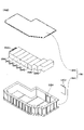
- FIG. 4 is a perspective view showing an example of a maintenance door of an upper revolving structure; It is a perspective view which shows an example of an electrical storage apparatus.
- FIG. 10 is a perspective view showing another example of a power storage device; 1 is an exploded view showing an example of a configuration of an electricity storage module;
- FIG. 3 is a cross-sectional view showing an example of a connection structure between power storage modules;
- FIG. 4 is a diagram for explaining a switching method between operation and stop of the DC-DC converter;
- FIG. 10 is a flowchart schematically showing an example of control processing relating to startup and shutdown of the charge mode of the excavator;
- FIG. 4 is a flowchart schematically showing an example of forced termination processing of the charging mode;
- 4 is a flowchart schematically showing a first example of control processing regarding use of an air conditioner while a power storage device is being charged;
- FIG. 10 is a flowchart schematically showing a second example of control processing regarding use of the air conditioner while the power storage device is being charged;
- FIG. 1 is a side view showing an example of a shovel 100 according to this embodiment.
- the excavator 100 includes a lower traveling body 1, an upper revolving body 3 mounted on the lower traveling body 1 so as to be rotatable (rotatable) via a revolving mechanism 2, an attachment AT, and a cabin 10 in which an operator rides. .
- the cabin 10 may be omitted when the shovel 100 is remotely controlled or fully automated.
- the lower traveling body 1 includes, for example, a pair of left and right crawlers 1C (an example of driven parts).
- the lower traveling body 1 is self-propelled by hydraulically driving the respective crawlers 1C by traveling hydraulic motors 1A and 1B (see FIGS. 2 and 3).
- the upper revolving body 3 (an example of a driven part) is hydraulically driven by a revolving hydraulic motor 2A through the revolving mechanism 2 (see FIGS. 2 and 3).
- the attachment AT includes a boom 4, an arm 5, and a bucket 6.
- a boom 4 (an example of a driven portion) is attached to the center of the front portion of the upper rotating body 3 so as to be able to be raised and lowered, and an arm 5 (an example of the driven portion) is attached to the tip of the boom 4 so as to be vertically rotatable.
- a bucket 6 (an example of a driven portion) is attached to the tip of the arm 5 so as to be vertically rotatable.
- the boom 4, arm 5, and bucket 6 are hydraulically driven by boom cylinders 7, arm cylinders 8, and bucket cylinders 9 as hydraulic actuators, respectively.
- the bucket 6 is an example of an end attachment and is used for excavation work, rolling compaction work, and the like.
- another end attachment may be attached to the tip of the arm 5 depending on the work content.
- Other end attachments may be different types of buckets than bucket 6, such as slope buckets, dredging buckets, and the like.
- Other end attachments may also be different types of end attachments than buckets, such as breakers, stirrers, grapplers, and the like.
- the connection between the end attachment including the bucket 6 and the arm 5 may be provided with an auxiliary attachment such as a quick coupling or a tiltrotator.
- the excavator 100 hydraulically drives all driven parts with hydraulic oil supplied from a main pump 14 (see FIG. 2) powered by a pump electric motor 12, as will be described later.
- the excavator 100 corresponds to a configuration in which the prime mover (engine) of a so-called hydraulic excavator is replaced with the pump electric motor 12 .
- the driven parts of the excavator 100 may be electrically driven.
- the upper revolving structure 3 may be revolved with respect to the lower traveling structure 1 by being electrically driven by a revolving electric motor through the revolving mechanism 2 .
- the cabin 10 is mounted, for example, on the front left side of the upper swing structure 3, and is provided with a cockpit in which an operator sits, an operation device 26, which will be described later, and the like.
- the cabin 10 may be omitted when the shovel 100 is remotely controlled or fully automated.
- the excavator 100 operates driven parts such as the lower traveling body 1 (left and right crawlers 1C), the upper revolving body 3, the boom 4, the arm 5, and the bucket 6 according to the operation of the operator riding in the cabin 10.
- the excavator 100 may be configured to be remotely controlled (remotely controlled) from the outside of the excavator 100.
- the interior of the cabin 10 may be unmanned. The following description is based on the premise that the operator's operation includes at least one of the operator's operation of the operating device 26 of the cabin 10 and the external operator's remote operation.
- Remote operation includes, for example, a mode in which the excavator 100 is operated by an operation input relating to the actuator of the excavator 100 performed by a predetermined external device.
- the external device includes, for example, a management device that manages the excavator 100, a terminal device (user terminal) that is used by the user of the excavator 100, and the like. The same may be applied to remote monitoring, which will be described later.
- the excavator 100 is equipped with a communication device capable of communicating with an external device. (hereinafter referred to as "peripheral image”) may be transmitted to the external device.
- the external device may cause a peripheral image of the excavator 100, which is received on a display device (hereinafter referred to as a “remote control display device”) provided in the external device, to be displayed.
- a display device hereinafter referred to as a “remote control display device”
- various information images (information screens) displayed on the output device 50 (display device) inside the cabin 10 of the excavator 100 may be similarly displayed on the remote control display device of the external device.
- the operator of the external device can remotely operate the excavator 100 while confirming the display contents such as the peripheral image of the excavator 100 and the information screen displayed on the remote control display device.
- the excavator 100 operates the actuators according to the remote control signal representing the content of the remote control received from the external device by the communication device, and the lower traveling body 1, the upper revolving body 3, the boom 4, the arm 5, and driven parts such as the bucket 6 may be driven.
- the remote operation may include, for example, a mode in which the excavator 100 is operated by external voice input or gesture input to the excavator 100 by people (eg, workers) around the excavator 100 .
- the excavator 100 uses a voice input device (for example, a microphone), a gesture input device (for example, an imaging device), or the like mounted on the excavator 100 (the excavator 100) to detect voices uttered by surrounding workers or the like. or gestures made by a worker or the like.
- the excavator 100 operates the actuators according to the contents of the recognized voice, gesture, etc., and drives the driven parts such as the lower traveling body, the upper rotating body 3, the boom 4, the arm 5, and the bucket 6. good too.
- the excavator 100 may automatically operate the actuator regardless of the details of the operator's operation.
- the excavator 100 has a function of automatically operating at least a part of the driven parts such as the lower traveling body 1, the upper rotating body 3, the boom 4, the arm 5, and the bucket 6 (a so-called “automatic driving function” or " MC (Machine Control) function”).
- the automatic operation function includes a function to automatically operate a driven part (actuator) other than the driven part (actuator) to be operated according to the operation of the operator's operation device 26 or remote control (so-called “semi-automatic operation function” Alternatively, an “operation-assisted MC function”) may be included.
- the automatic operation function includes a function that automatically operates at least a part of a plurality of driven parts (actuators) on the premise that the operator does not operate the operation device 26 or remote operation (so-called “fully automatic operation function” or “Fully automated MC functionality”) may be included.
- the excavator 100 when the fully automatic operation function is effective, the inside of the cabin 10 may be in an unmanned state.
- the semi-automatic operation function, the fully automatic operation function, and the like may include a mode in which the operation contents of the driven parts (actuators) to be automatically operated are automatically determined according to rules that are defined in advance.
- the excavator 100 autonomously makes various judgments, and according to the judgment results, the operation contents of the driven parts (actuators) to be autonomously operated automatically. is determined (so-called “autonomous driving function”).
- the work status of the excavator 100 may be remotely monitored from the outside of the excavator 100 .
- the excavator 100 When remote monitoring is performed, the excavator 100 is equipped with a communication device capable of communicating with an external device. (peripheral image) may be transmitted to the external device. Then, the external device may display the received image information (captured image) on a display device (hereinafter referred to as “remote monitoring display device”) provided in the external device. Various information images (information screens) displayed on the output device 50 (display device) inside the cabin 10 of the excavator 100 may be similarly displayed on the remote monitoring display device of the external device. As a result, the monitor of the external device can remotely monitor the work status of the excavator 100 while confirming the display contents such as the peripheral image of the excavator 100 and the information screen displayed on the remote monitoring display device. .
- the supervisor of the external device can make an emergency stop of the operation of the excavator 100 by performing a predetermined input to the external device, or It may be possible to perform an intervention operation of In this case, the excavator 100 stops the actuators in response to a signal indicating an emergency stop received from an external device through the communication device.
- the driven parts such as the bucket 6 may be brought to an emergency stop.
- the excavator 100 operates the actuators in response to a signal representing the content of the intervention operation received from the external device through the communication device, thereby operating the lower traveling body 1, the upper rotating body 3, the boom 4, the arm 5, and intervention operation of driven parts such as the bucket 6 may be realized.
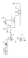
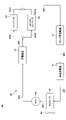
- FIG. 2 and 3 are block diagrams schematically showing one example and another example of the configuration of the shovel 100 according to this embodiment.
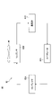
- FIG. 4 is a diagram showing an example of a configuration related to operation limitation of the hydraulic drive system.
- FIG. 5 is a diagram showing another example of a configuration related to operation limitation of the hydraulic drive system.
- FIG. 6 is a diagram showing an example of the cooling device 60 mounted on the shovel 100 according to this embodiment.
- FIG. 7 is a diagram showing an example of the heat pump cycle 82 of the air conditioner 80 mounted on the excavator 100 according to this embodiment.
- the mechanical power transmission system is represented by a double line
- the relatively high hydraulic pressure transmission system that is, the hydraulic oil line of the hydraulic drive system is represented by a thick solid line
- the pilot pressure transmission system that is, , hydraulic oil lines of the operation system are indicated by dashed lines
- electric power and electric signal transmission systems are indicated by thin solid lines.
- the excavator 100 includes components such as a hydraulic drive system, an electric drive system, a power supply system, an operation system, a cooling system, a user interface system, a comfort equipment system, and a control system.
- the hydraulic drive system of the excavator 100 is a group of components related to hydraulic drive of the driven parts.
- the hydraulic drive system of the excavator 100 includes traveling hydraulic motors 1A and 1B that hydraulically drive driven parts such as the lower traveling body 1, boom 4, arm 5, and bucket 6, boom cylinder 7, arm cylinder 8, and bucket. Hydraulic actuators such as cylinder 9 are included.
- the hydraulic drive system of the excavator 100 also includes a pump electric motor 12 , a main pump 14 and a control valve 17 .
- the pump electric motor 12 (an example of an electric motor) is the power source of the hydraulic drive system.
- the pump electric motor 12 is, for example, an IPM (Interior Permanent Magnet) motor.
- Pump motor 12 is connected to power storage device 19 via inverter 18 .
- the pump motor 12 is powered by three-phase AC power supplied from the power storage device 19 via the inverter 18 to drive the main pump 14 and the pilot pump 15 .
- Drive control of the pump motor 12 may be performed by the inverter 18 under the control of the controller 30B, which will be described later.
- the main pump 14 (hydraulic pump, an example of a first hydraulic pump) sucks hydraulic oil from the hydraulic oil tank T and discharges it to the high pressure hydraulic line 16 to supply the hydraulic oil to the control valve 17 through the high pressure hydraulic line 16. do.
- the main pump 14 is driven by the pump motor 12 as described above.
- the main pump 14 is, for example, a variable displacement hydraulic pump, and a regulator (not shown) controls the angle (tilt angle) of the swash plate under the control of a controller 30A, which will be described later. Thereby, the main pump 14 can adjust the stroke length of the piston and adjust the discharge flow rate (discharge pressure).
- the control valve 17 controls the hydraulic drive system according to the operator's operation and the operation command corresponding to the automatic operation function.
- the control valve 17 is connected to the main pump 14 via the high-pressure hydraulic line 16, and is configured to selectively supply hydraulic fluid supplied from the main pump 14 to a plurality of hydraulic actuators.
- the control valve 17 is a valve unit that includes a plurality of control valves (directional switching valves) that control the flow rate and flow direction of hydraulic oil supplied from the main pump 14 to each hydraulic actuator.
- the hydraulic fluid supplied from the main pump 14 and passed through the control valve 17 and the hydraulic actuator is discharged from the control valve 17 into the hydraulic fluid tank T.
- the electric drive system of the excavator 100 is a group of components related to the electric drive of the prime mover (power source) and driven parts of the excavator 100 .
- the electric drive system of the excavator 100 includes a pump motor 12, a sensor 12s, and an inverter 18.
- the electric drive system of the shovel 100 may include an electric actuator for driving the driven section, an inverter for driving the electric actuator, or the like when part or all of the driven section is electrically driven as described above.
- the sensor 12s includes a current sensor 12s1, a voltage sensor 12s2, and a rotation state sensor 12s3.
- the current sensor 12s1 detects the current of each of the three phases (U-phase, V-phase, and W-phase) of the pump motor 12.
- the current sensor 12s1 is provided in a power path between the pump motor 12 and the inverter 18, for example. Detection signals corresponding to currents of the three phases of the pump motor 12 detected by the current sensor 12s1 are directly taken into the inverter 18 through the communication line. Further, the detection signal may be taken into the controller 30B through the communication line and inputted to the inverter 18 via the controller 30B.
- the voltage sensor 12s2 detects the voltage applied to each of the three phases of the pump motor 12.
- the voltage sensor 12s2 is provided in a power path between the pump motor 12 and the inverter 18, for example.
- a detection signal corresponding to the voltage applied to each of the three phases of the pump motor 12 detected by the voltage sensor 12s2 is directly taken into the inverter 18 through the communication line. Further, the detection signal may be taken into the controller 30B through the communication line and inputted to the inverter 18 via the controller 30B.
- the rotation state sensor 12s3 detects the rotation state of the pump electric motor 12.
- the rotational state of the pump motor 12 includes, for example, rotational position (rotational angle), rotational speed, and the like.
- the rotation state sensor 12s3 is, for example, a rotary encoder or resolver.
- a detection signal corresponding to the rotation state of the pump motor 12 detected by the rotation state sensor 12s3 is directly taken into the inverter 18 through the communication line. Further, the detection signal may be taken into the controller 30B through the communication line and inputted to the inverter 18 via the controller 30B.
- the inverter 18 drives and controls the pump motor 12 under the control of the controller 30B.
- the inverter 18 defines, for example, a conversion circuit that converts DC power into three-phase AC power or converts three-phase AC power into DC power, a drive circuit that switches the conversion circuit, and the operation of the drive circuit. and a control circuit that outputs a control signal for The control signal is, for example, a PWM (Pulse Width Modulation) signal.
- PWM Pulse Width Modulation
- the control circuit of the inverter 18 performs drive control of the pump motor 12 while grasping the operating state of the pump motor 12 .
- the control circuit of the inverter 18 grasps the operation state of the pump motor 12 based on the detection signal of the rotation state sensor 12s3.
- the control circuit of the inverter 18 sequentially adjusts the rotation angle of the rotating shaft of the pump electric motor 12 based on the detection signal of the current sensor 12s1 and the detection signal of the voltage sensor 12s2 (or the voltage command value generated in the control process). By estimating, the operating state of the pump motor 12 may be grasped.
- At least one of the drive circuit and control circuit of the inverter 18 may be provided outside the inverter 18 .
- the power supply system of the excavator 100 is a group of components for supplying power to various electric devices.
- the power supply system of the excavator 100 includes a power storage device 19, a DC-DC converter 44, a battery 46, an onboard charger 70, and a charging port 72.
- the power storage device 19 is an energy source for driving the actuator of the excavator 100 .
- the power storage device 19 is charged (accumulated) by being connected to an external commercial power source with a predetermined cable (hereinafter referred to as “charging cable”), and supplies the charged (accumulated) power to the pump motor 12 .
- the power storage device 19 is, for example, a lithium ion battery and has a relatively high output voltage (eg, several hundred volts).
- a power conversion device may be provided between the power storage device 19 and the pump motor 12 to boost the output voltage of the power storage device 19 and apply it to the pump motor 12 . Further, as described above, when part or all of the driven parts are electrically driven, electric power from the power storage device 19 is supplied to the electric actuator that electrically drives the driven parts instead of or in addition to the pump motor 12 . supplied.
- a DC-DC converter 44 (an example of a power conversion device) is provided, for example, in the upper revolving body 3, and converts the very high voltage DC power output from the power storage device 19 to a predetermined voltage (eg, about 24 volts). Step down and output.
- the output power of the DC-DC converter 44 is supplied to the battery 46 to be charged (accumulated) or supplied to an electrical device (hereinafter referred to as "low voltage device") driven by the power of the battery 46.
- the low-voltage equipment includes, for example, various controllers (controllers 30A to 30E, etc.) included in the control device 30.
- the low-voltage equipment includes, for example, a water pump 64, an air conditioner 80, a fan 90, etc., which will be described later.
- the excavator 100 is equipped with one DC-DC converter 44 .
- the DC-DC converter 44 may include a plurality of DC-DC converters connected in parallel (two DC-DC converters 44A and 44B in this example).
- the plurality of DC-DC converters 44A and 44B can share and output the current required by the low-voltage equipment.
- the DC-DC converters 44A and 44B have a relatively small current capacity, that is, the maximum value of the current that can be output, and thus have a relatively small external size. Therefore, the degree of freedom of arrangement when mounted on the upper revolving body 3 can be improved. Further, even if one of the plurality of DC-DC converters 44A and 44B cannot supply power due to an abnormality or the like, the other can continue to supply power.
- the DC-DC converter 44 may be replaced with an alternator.
- the alternator may be provided in the upper revolving body 3 and generate power using the power of the pump electric motor 12 .
- the power generated by the alternator is supplied to the battery 46, charged (accumulated) in the battery 46, or supplied to low-voltage devices such as the controllers 30A to 30E, as in the case of the DC-DC converter 44.
- a battery 46 is provided in the upper slewing body 3 and has a relatively low output voltage (eg, 24 volts).
- the battery 46 powers low voltage equipment other than the electric drive system that requires relatively high power.
- the battery 46 is, for example, a lead-acid battery, a lithium-ion battery, or the like, and is charged with the output power of the DC-DC converter 44 as described above.
- the in-vehicle charger 70 converts single-phase AC power of relatively low voltage (for example, 100 volts or 200 volts) supplied from an external power source into DC power through a charging port 72A, which will be described later, and outputs the DC power to the power storage device 19. Thus, the power storage device 19 is charged.
- relatively low voltage for example, 100 volts or 200 volts
- the charging port 72 is provided, for example, on the side surface of the upper rotating body 3, and is connected by inserting the tip of a charging cable extending from an external power source.
- Charging port 72 includes charging ports 72A and 72B.
- a charging cable extending from an external power supply (for example, a commercial power supply) capable of supplying relatively low-voltage single-phase AC power, for example, is configured to be connectable to the charging port 72A.
- the charging port 72 ⁇ /b>A is connected to the vehicle-mounted charger 70 by a power line (wire harness), and supplies power supplied from an external power supply to the power storage device 19 through the vehicle-mounted charger 70 .
- a power line wire harness
- a charging cable extending from an external power supply capable of supplying relatively high voltage (eg, 400 volts) DC power is connected to the charging port 72B.
- the charging port 72B is directly connected to the power storage device 19 by a power line (wire harness), and directly supplies the power storage device 19 with DC power supplied from an external power supply.
- a power line wire harness
- the operation system of the excavator 100 is a group of components related to the operation of the driven parts.
- the operating system of the excavator 100 includes a pilot pump 15, an operating device 26, and a hydraulic control valve 31. Further, as shown in FIG. 4, the operating system of the excavator 100 includes a gate lock valve 25V1, a gate lock switch 25SW, and a relay 25R. Further, as shown in FIG. 5, the operating system of the excavator 100 may include a switching valve 25V2 in addition to the relay 25R.
- a pilot pump 15 (an example of a second hydraulic pump) supplies pilot pressure to various hydraulic devices (eg, hydraulic control valve 31) mounted on the excavator 100 via a pilot line 25.
- the hydraulic control valve 31 can supply the pilot pressure to the control valve 17 under the control of the controller 30A according to the operation content (for example, the operation amount and the operation direction) of the operating device 26 . Therefore, the controller 30 ⁇ /b>A and the hydraulic control valve 31 can realize the operation of the driven part (hydraulic actuator) according to the operation content of the operation device 26 by the operator.
- the hydraulic control valve 31 can supply the control valve 17 with a pilot pressure corresponding to the details of the remote operation designated by the remote operation signal under the control of the controller 30A.
- the hydraulic control valve 31 can supply the control valve 17 with a pilot pressure according to an operation command corresponding to the automatic operation function under the control of the controller 30A.
- the pilot pump 15 is, for example, a fixed displacement hydraulic pump, and is driven by the pump motor 12 as described above.
- pilot pump 15 may be omitted.
- various hydraulic devices such as the hydraulic control valve 31 may be supplied with hydraulic fluid discharged from the main pump 14 and reduced to a predetermined pilot pressure via a pressure reducing valve or the like.
- the operation device 26 is provided within the reach of the operator in the cockpit of the cabin 10, and the operator can operate the driven parts (that is, the left and right crawlers 1C of the lower traveling body 1, the upper revolving body 3, the boom 4, and the arm). 5, and bucket 6, etc.).
- the operation device 26 is used by the operator to operate the actuators (for example, the traveling hydraulic motors 1A and 1B, the boom cylinder 7, the arm cylinder 8, the bucket cylinder 9, etc.) that drive the respective driven parts. Used.
- the operating device 26 is of an electrical type, and outputs electrical signals (hereinafter referred to as "operation signals") according to the content of operations by the operator.
- control device 30 including the controller 30A controls the hydraulic control valve 31 and the like, and operates the driven parts (actuators) of the excavator 100 in accordance with the operator's operation contents and the operation command corresponding to the automatic operation function. can be controlled.
- the operating device 26 includes, for example, levers 26A-26C.
- the lever 26A may be configured, for example, to be able to receive operations related to the arm 5 (arm cylinder 8) and the upper rotating body 3 (rotating motion) according to operations in the front-rear direction and the left-right direction.
- the lever 26B may be configured to be able to receive operations related to the boom 4 (boom cylinder 7) and the bucket 6 (bucket cylinder 9) in response to operations in the longitudinal direction and the lateral direction.
- the lever 26C may be configured, for example, to be able to receive an operation of the undercarriage 1 (crawler 1C).
- control valve 17 When the control valve 17 is composed of an electromagnetic pilot type hydraulic control valve (directional switching valve), the operation signal of the electric operating device 26 is directly input to the control valve 17, and each hydraulic control valve is operated. A mode of performing an operation according to the operation content of the device 26 may be employed. Further, the operating device 26 may be of a hydraulic pilot type that outputs a pilot pressure corresponding to the content of the operation. In this case, the pilot pressure corresponding to the operation content is supplied to the control valve 17 .
- electromagnetic pilot type hydraulic control valve directional switching valve
- the hydraulic control valve 31 outputs a predetermined pilot pressure using hydraulic oil supplied from the pilot pump 15 through the pilot line 25 under the control of the controller 30A.
- a pilot line on the secondary side of the hydraulic control valve 31 is connected to the control valve 17 , and the pilot pressure output from the hydraulic control valve 31 is supplied to the control valve 17 .
- the gate lock valve 25V1 is a switching valve provided in the pilot line 25.
- the gate lock valve 25V1 is, for example, an electromagnetic solenoid valve.
- the gate lock valve 25V1 When the gate lock valve 25V1 is in a non-energized state (states shown in FIGS. 4 and 5), the elastic force of the gate lock valve 25V1 maintains the spool at the right position in the drawing, and the pilot line 25 is placed in a non-communication state. In this case, the gate lock valve 25V1 discharges hydraulic fluid in the downstream pilot line 25 to the hydraulic fluid tank T.
- the gate lock valve 25V1 when the gate lock valve 25V1 is energized, the spool moves leftward against the elastic force due to the action of the electromagnetic solenoid, and the pilot line 25 is brought into communication. In this case, the gate lock valve 25V1 supplies hydraulic fluid for the pilot pump 15 to the downstream side.
- the gate lock switch 25SW is provided on the power line between the battery 46 and the gate lock valve 25V1 (electromagnetic solenoid). When the gate lock switch 25SW is off, it opens the power line and turns off the gate lock valve 25V1. When it is on, it closes the power line and turns on the gate lock valve 25V1.
- the gate lock switch 25SW is turned on and off according to the operating state of the gate lock lever inside the cabin 10.
- the gate lock switch 25SW is, for example, a limit switch interlocked with the operation of the gate lock lever.
- the gate lock switch 25SW is turned off when the gate lock lever is in the state in which the gate bar is pulled up, that is, in the operating state corresponding to the state in which the cockpit of the cabin 10 is opened to allow boarding and exiting.
- the gate lock valve 25V1 keeps the pilot line 25 out of communication when the gate bar is pulled up. Therefore, the gate lock switch 25SW operates the gate lock valve 25V1 so that the pilot pressure is not supplied to the hydraulic control valve 31 in accordance with the situation where the operator of the cabin 10 does not intend to operate the cabin 10 or the operator is absent from the cabin 10. can be operated.
- the gate lock switch 25SW is turned on when the gate bar is lowered, that is, when the operator's seat of the cabin 10 is closed to prevent boarding and exiting.
- the gate lock switch 25SW can operate the gate lock valve 25V1 so that the pilot pressure is supplied to the hydraulic control valve 31 in accordance with the situation where the operator of the cabin 10 has an intention to operate.
- the relay 25R is used to cut off (disconnect) the pilot line 25 regardless of the operating state of the gate lock lever, that is, the state of the gate lock switch 25SW.
- the relay 25R is arranged on the power line between the battery 46 and the gate lock valve 25V1 (electromagnetic solenoid).
- the relay 25R is of a normally closed type, and is opened when energized by the control current input from the controller 30A.
- the controller 30A energizes the relay 25R and opens the relay 25R, thereby deenergizing the gate lock valve 25V1 even when the gate lock switch 25SW is on, and disconnecting the pilot line 25. can be moved to Therefore, the control device 30 (controller 30A) can stop the operation of the driven portion (hydraulic actuator).
- the relay 25R may be provided on the power line between the battery 46 and the switching valve 25V2 (electromagnetic solenoid).
- the relay 25R is of a normally open type, and is closed when energized by the control current input from the controller 30A.
- the switching valve 25V2 is provided in the pilot line 25.
- the switching valve 25V2 may be provided downstream of the gate lock valve 25V1 in the pilot line 25, or may be provided upstream of the gate lock valve 25V1.
- the switching valve 25V2 is, for example, an electromagnetic solenoid valve.
- the switching valve 25V2 maintains the spool at the right position in the drawing due to its elastic force in the non-energized state (the state in FIG. 5), and brings the pilot line 25 into the open state.
- the switching valve 25V2 is energized, the spool moves leftward against the elastic force due to the action of the electromagnetic solenoid, and the pilot line 25 is disconnected.
- the relay 25R When the coil of the relay 25R is not energized, the relay 25R is opened, so the switching valve 25V2 maintains the pilot line 25 in a communication state. On the other hand, when the coil of the relay 25R is energized by the controller 30A, the relay 25R is closed, so the switching valve 25V2 maintains the pilot line 25 in a disconnected state. Thereby, the control device 30 (controller 30A) can shift the switching valve 25V2 to the non-communication state even when the gate lock valve 25V1 is in the communication state. Therefore, the control device 30 (controller 30A) can stop the operation of the driven portion (hydraulic actuator).
- the relay 25R and the switching valve 25V2 may be omitted.
- the control device 30 may limit the operation of the driven portion (hydraulic actuator) by controlling the pilot pressure output from the hydraulic control valve 31, for example.
- the cooling system of the excavator 100 is a group of components for cooling components that generate heat as the excavator 100 operates.
- the cooling system of the shovel 100 includes a cooling device 60 and a fan 90.
- the cooling device 60 cools the electric drive system equipment and relatively high voltage power supply system equipment in the excavator 100 .
- equipment to be cooled by the cooling device 60 includes the pump motor 12, the inverter 18, the power storage device 19, the DC-DC converter 44, the vehicle charger 70, and the like.
- the connection mode in the refrigerant circuit 66 of the object to be cooled which is configured so that the refrigerant can pass through or through the refrigerant circuit 66, is arbitrary. you can That is, as long as the conditions regarding the cooling performance required for each of the plurality of objects to be cooled are satisfied, the plurality of objects to be cooled cooled by the refrigerant circuit 66 may be partially or entirely connected in series. Or all may be connected in parallel.
- the order of arranging the plurality of objects to be cooled in the refrigerant circuit 66 with the radiator 62 as a starting point may be arbitrary as long as the conditions regarding the required cooling performance for each of the plurality of objects to be cooled are satisfied.
- the cooling device 60 includes a radiator 62 , a water pump 64 and a refrigerant circuit 66 .
- the radiator 62 cools the refrigerant (for example, cooling water) inside the refrigerant circuit 66 . Specifically, the radiator 62 causes heat exchange between the surrounding air and the refrigerant to cool the refrigerant.
- the refrigerant for example, cooling water
- a water pump 64 (an example of an electric load, a refrigerant pump) circulates the refrigerant within the refrigerant circuit 66 .
- the water pump 64 operates with power supplied from the DC-DC converter 44 or the battery 46, for example.
- a refrigerant circuit 66 (an example of a circulation circuit) includes refrigerant flow paths 66A, 66B, 66C, 66C1, 66C2, 66D, 66D1, 66D2, 66E, and 66F.
- the coolant channel 66A connects between the water pump 64 and the power storage device 19, and causes the coolant discharged from the water pump 64 to flow into the coolant channel inside or around the power storage device 19. Thereby, cooling device 60 can cool power storage device 19 with the coolant.
- the refrigerant flow paths 66B, 66B1, 66B2 connect between the power storage device 19, the inverter 18 and the DC-DC converter 44.
- Refrigerant passages 66B, 66B1, and 66B2 cause the refrigerant flowing out from the refrigerant passages inside or around the power storage device 19 to flow into the refrigerant passages inside or around the inverter 18 and the DC-DC converter .
- a refrigerant flow path 66B one end of which is connected to the power storage device 19, branches into refrigerant flow paths 66B1 and 66B2 at the other end, which are connected to the inverter 18 and the DC-DC converter 44, respectively.
- the refrigerant passages 66B1 and 66B2 allow the refrigerant to flow into the refrigerant passages inside or around the inverter 18 and the DC-DC converter .
- the cooling device 60 can cool the inverter 18 and the DC-DC converter 44 with the refrigerant.
- the coolant that flows through the coolant channel inside or around the inverter 18 flows out to the coolant channel 66C1.
- the coolant flowing through the coolant channel inside or around the DC-DC converter 44 flows out to the coolant channel 66C2.
- the refrigerant flow paths 66C, 66C1, 66C2 connect between the inverter 18 and the DC-DC converter 44 and the pump motor 12.
- the refrigerant passages 66C, 66C1, 66C2 cause the refrigerant flowing out from the refrigerant passages inside or around the inverter 18 and the DC-DC converter 44 to flow into the refrigerant passages inside or around the pump motor 12 .
- the refrigerant flow paths 66C1 and 66C2 one ends of which are respectively connected to the inverter 18 and the DC-DC converter 44, join one end of the refrigerant flow path 66C, and the other end of the refrigerant flow path 66C connects to the pump motor. 12.
- the cooling device 60 can cool the pump electric motor 12 with the refrigerant.
- the coolant that flows through the coolant channel inside or around the pump motor 12 flows out to the coolant channel 66D.
- the power conversion device may be cooled by the cooling device 60 .
- the power conversion device may be arranged in parallel with the inverter 18 and the DC-DC converter 44 in the refrigerant circuit 66 and cooled by the refrigerant flowing out from the power storage device 19 .
- the DC-DC converter 44 may be air-cooled.
- the coolant channels 66B2 and 66C2 are omitted.
- at least part of the inverter 18 and the DC-DC converter 44 may be arranged in series in the refrigerant circuit 66 .
- the coolant flow path 66D connects between the pump motor 12 and the on-vehicle charger 70, and allows the coolant flowing out from the coolant flow path inside or around the pump motor 12 to pass through the coolant flow inside or around the on-vehicle charger 70. flow into the road. Thereby, the cooling device 60 can cool the vehicle-mounted charger 70 with the refrigerant. The coolant that flows through the coolant channel inside or around the vehicle-mounted charger 70 flows out to the coolant channel 66E.
- the coolant channel 66E connects between the onboard charger 70 and the radiator 62, and supplies the radiator 62 with the coolant that flows out from the coolant channel inside or around the onboard charger 70.
- the refrigerant circuit 66 cools various devices in the electric drive system and the power supply system, so that the coolant whose temperature has risen is cooled by the radiator 62, and the various devices in the electric drive system and the power system can be cooled again. can be restored to good condition.
- the coolant flow path 66F connects between the radiator 62 and the water pump 64, and supplies coolant cooled by the radiator 62 to the water pump 64.
- the water pump 64 can discharge the coolant cooled by the radiator 62 to the coolant passage 66A and circulate the coolant in the coolant circuit 66 .
- the fan 90 (an example of an electric load and a cooling fan) operates under the control of the control device 30 (for example, the controller 30A) and is a predetermined device that exchanges heat with the air (hereinafter referred to as "heat exchange device"). blow air toward The fan 90 operates with power supplied from the DC-DC converter 44 or the battery 46, for example.
- the fan 90 may blow air toward the radiator 62 to cool the radiator 62, for example, as shown in FIG. As a result, air capable of exchanging heat with the refrigerant flowing inside is sequentially supplied around the radiator 62, and the degree of cooling of the refrigerant by the radiator 62 can be increased. .
- the number of fans 90 may be one, or may be plural as described later. In other words, the number of fans 90 may be any number as long as the degree of heat exchange (degree of cooling or degree of heating) necessary for the heat exchange device can be ensured.
- the cooling system of the excavator 100 may include an oil cooler that cools hydraulic oil used in the hydraulic drive system (high pressure hydraulic line) and operation system (pilot line).
- the oil cooler is provided, for example, in the return oil passage between the control valve 17 and the hydraulic oil tank T, and cools the hydraulic oil by exchanging heat between the surrounding air and the hydraulic oil flowing inside. you can In this case, the fan 90 may blow air toward the oil cooler to cool the oil cooler. As a result, the surroundings of the oil cooler are successively supplied with air capable of exchanging heat with the hydraulic oil flowing through the inside, thereby increasing the degree of cooling of the hydraulic oil by the oil cooler. can be done. In this case, the fan 90 that blows air to the radiator 62 and the fan 90 that blows air to the oil cooler may be the same fan 90 or different fans 90 .
- the user interface system of the excavator 100 is a group of components related to information exchange with the user.
- the user interface system includes an output device 50 and an input device 52.
- the output device 50 (an example of a notification device) outputs various information to the user under the control of the control device 30 (eg, controller 30A).
- the output device 50 is provided inside the cabin 10 and includes an output device that outputs various information to a user (for example, an operator) inside the cabin 10 .
- the output device 50 includes an output device that is provided outside the cabin 10 and outputs various information to users around the excavator 100 (for example, workers, supervisors, etc. around the excavator 100). It's okay.
- the output device 50 includes, for example, a display device and a lighting device that output (notify) information to the user in a visual manner.
- the display device may display various information images under the control of the controller 30A.
- the display device is, for example, a liquid crystal display or an organic EL (Electroluminescence) display.
- the lighting device is, for example, a warning light or the like.
- the output device 50 also includes, for example, a sound output device that outputs information to the user in an auditory manner.
- the sound output device is, for example, a buzzer, a speaker, or the like.
- the input device 52 accepts various inputs from the user.
- the input device 52 includes an input device that is provided inside the cabin 10 and receives various inputs from a user (for example, an operator) inside the cabin 10 .
- the input device 52 may include an input device that is provided outside the cabin 10 and receives various inputs from users outside the cabin 10 (for example, workers around the excavator 100, supervisors, etc.). .
- the input device 52 may include, for example, an operation input device that receives a user's operation input.
- Operation input devices include, for example, buttons, toggles, levers, touch panels, touch pads, and the like.
- the input device 52 may also include, for example, a voice input device that receives voice input from the operator and a gesture input device that receives gesture input from the operator.
- a voice input device includes, for example, a microphone that captures the user's voice.
- the gesture input device includes, for example, a camera capable of capturing an image of the user's gesture.
- a signal corresponding to an operator's input received by the input device 52 is captured by the control device 30 (for example, the controller 30A).
- the comfort equipment system of the excavator 100 is a group of components related to comfort equipment for the user (operator) inside the cabin 10 .
- the comfort equipment system of the shovel 100 includes an air conditioner 80. Further, as shown in FIG. 7 , the comfort equipment system of the excavator 100 includes a fan 90 .
- the air conditioner 80 (an example of an electrical load) adjusts the state of the air inside the cabin 10, specifically the temperature and humidity of the air.
- the air conditioner 80 operates with electric power supplied from the DC-DC converter 44 or the battery 46, for example.
- the air conditioner 80 is, for example, a heat pump type for both cooling and heating, and includes a heat pump cycle 82 .
- the air conditioner 80 may include, for example, a refrigeration cycle and a heater for heating instead of the heat pump cycle 82 .
- the heating heater is, for example, a PTC (Positive Temperature Coefficient) heater, a combustion heater, or the like.
- the heat pump cycle 82 includes a compressor 82A, a condenser 82B, an expansion valve 82C and an evaporator 82D.
- the arrows in FIG. 7 represent the flow of the refrigerant during the cooling operation of the air conditioner 80, and the flow of the refrigerant during the heating operation of the air conditioner 80 is reversed.
- the compressor 82A compresses the refrigerant in the heat pump cycle 82.
- the compressor 82A includes, for example, a built-in electric motor and an inverter circuit for driving the electric motor, and is electrically driven by electric power supplied from the battery 46 or the DC-DC converter 44.
- the refrigerant compressed by compressor 82A is sent to condenser 82B when air conditioner 80 is in cooling operation, and is sent to evaporator 82D when air conditioner 80 is in heating operation.
- the compressor 82A may be configured to be driven by electric power directly supplied from the power storage device 19. Further, the compressor 82A may be configured to be mechanically driven by the pump electric motor 12 .
- the condenser 82B cools the gaseous refrigerant that has been compressed by the compressor 82A and rises to a relatively high temperature during the cooling operation of the air conditioner 80 . Specifically, the condenser 82B radiates the heat of the refrigerant to the outside air through heat exchange between the refrigerant flowing inside and the outside air, thereby cooling the refrigerant. The refrigerant cooled by condenser 82B changes to a liquid state.
- the condenser 82B takes heat from the outside air through heat exchange between the refrigerant flowing inside and the outside air, and the pressure is reduced through the expansion valve 82C, resulting in a relatively low temperature. to increase the temperature of the refrigerant.
- the expansion valve 82C abruptly lowers the pressure of the flowing refrigerant and lowers the temperature of the refrigerant.
- the expansion valve 82C abruptly lowers the pressure of the liquid state and high pressure state refrigerant sent from the condenser 82B during the cooling operation of the air conditioner 80, thereby lowering the temperature. Further, the expansion valve 82C rapidly lowers the pressure of the liquid state and high pressure state refrigerant sent from the evaporator 82D during the heating operation of the air conditioner 80, thereby lowering the temperature.
- the evaporator 82D exchanges heat between the refrigerant flowing inside and the air sent from the air conditioner 80 into the cabin 10.
- the evaporator 82D reduces the air sent into the cabin 10 in such a manner that the relatively low-temperature refrigerant (gas-liquid mixed state) sent from the expansion valve 82C takes heat from the air. cool.
- the evaporator 82D heats the air sent into the cabin 10 in such a manner that the air takes heat from the relatively high-temperature refrigerant (gas state) sent from the compressor 82A during the heating operation of the air conditioner 80. .
- the fan 90 may blow air toward the condenser 82B to cool or heat the condenser 82B.
- air capable of exchanging heat with the refrigerant flowing through the condenser 82B is sequentially supplied around the condenser 82B, thereby increasing the degree of cooling and heating of the refrigerant by the condenser 82B. be able to.
- the control system of the excavator 100 is a group of components related to various controls of the excavator 100 .
- the control system of the excavator 100 includes a control device 30. Also, the control system of the excavator 100 includes a peripheral information acquisition device 40 , a sensor 48 , and temperature sensors 54 and 56 .
- the control device 30 includes controllers 30A to 30E.
- controllers 30B-30E may be integrated into the controller 30A. That is, the various functions realized by the control device 30 may be realized by one controller, or may be distributed and realized by two or more controllers that are appropriately set.
- the functions of the controllers 30A to 30E may be realized by arbitrary hardware or a combination of arbitrary hardware and software.
- the controllers 30A to 30E each include a CPU (Central Processing Unit), a memory device such as RAM (Random Access Memory), an auxiliary storage device such as ROM (Read Only Memory), and an interface device with the outside. It consists mainly of a computer including
- the controllers 30A to 30E implement various functions by, for example, loading a program installed in the auxiliary storage device into the memory device and executing it on the CPU.
- the controller 30A cooperates with various controllers that make up the control device 30 including the controllers 30B to 30E, and performs drive control of the excavator 100.
- the controller 30A outputs a control command to the hydraulic control valve 31 according to an operation signal input from the operating device 26, and causes the hydraulic control valve 31 to output a pilot pressure corresponding to the operation content of the operating device 26.
- the controller 30 ⁇ /b>A can realize the operation of the driven portion (hydraulic actuator) of the excavator 100 corresponding to the operation content of the electric operating device 26 .
- the controller 30A may, for example, perform control related to remote operation. Specifically, the controller 30A may output a control command to the hydraulic control valve 31 and cause the hydraulic control valve 31 to output a pilot pressure according to the details of the remote operation. Thereby, the controller 30A can realize the operation of the driven portion (hydraulic actuator) of the excavator 100 corresponding to the contents of the remote operation.
- the controller 30A may, for example, perform control related to the automatic driving function. Specifically, the controller 30A may output a control command to the hydraulic control valve 31 and cause the control valve 17 to act on the pilot pressure from the hydraulic control valve 31 according to the operation command corresponding to the automatic operation function. Thereby, the controller 30A can realize the operation of the driven portion (hydraulic actuator) of the excavator 100 corresponding to the automatic operation function.
- controller 30A may integrally control the operation of the entire excavator 100 (various devices mounted on the excavator 100) based on two-way communication with various controllers such as the controllers 30B to 30E.
- the controller 30B controls the electric drive system based on various information input from the controller 30A (for example, control commands including operation signals of the operating device 26).
- the controller 30B for example, outputs a control command to the inverter 18 and controls the drive of the pump motor 12.
- the controller 30B when a power conversion device is provided between the power storage device 19 and the pump motor 12, the controller 30B, for example, outputs a control command to the power conversion device to control the operation of the power conversion device. you can go
- the controller 30C controls the peripheral monitoring function of the excavator 100.
- the controller 30C detects a predetermined object (hereinafter referred to as a “monitoring object”) around the excavator 100 based on data about the three-dimensional space situation around the excavator 100, which is acquired from the surrounding information acquisition device 40, for example. , to estimate the position of the monitored object.
- Objects to be monitored include, for example, people.
- the objects to be monitored include, for example, other working vehicles, other working machines, and the like.
- Observed objects may also include, for example, utility poles, pylons, fences, site materials, and the like.
- the data on the three-dimensional space situation around the excavator 100 includes, for example, detection data on objects around the excavator 100 and their positions.
- the controller 30C warns the user of the cabin 10 and the surroundings of the excavator 100 through the output device 50 (for example, a display device, a sound output device, etc.).
- the monitoring range is appropriately set as, for example, a range in which the distance from the excavator 100 around the excavator 100 is relatively short.
- controller 30C may limit the operation of the driven portion (actuator) of the shovel 100, for example, when a monitored object is detected within a predetermined monitoring range.
- Restrictions on the movement of the driven part include, for example, stopping the movement of the driven part.
- the controller 30C may, for example, output a request signal to the controller 30A to open the relay 25R, thereby forcibly stopping the operation of the driven part (hydraulic actuator).
- the controller 30C may output a request signal to the controller 30A to invalidate the operator's operation or operation command, thereby forcibly stopping the operation of the driven part (hydraulic actuator).
- the limitation of the movement of the driven part includes, for example, deceleration of the movement of the driven part.
- the controller 30C for example, outputs a request signal to the controller 30A, relatively reduces the pilot pressure output from the hydraulic control valve 31 to the control valve 17, and controls the driven part (hydraulic actuator) in response to the operator's operation or operation command. may be slowed down.
- the controller 30D controls the power storage device 19.
- the controller 30D controls charging of the power storage device 19, for example.
- the controller 30D detects various states of the power storage device 19 (for example, current state, voltage state, temperature state, charge state, deterioration state, presence/absence of abnormality, etc.) based on outputs of various sensors built in the power storage device 19, for example. Monitor.
- states of the power storage device 19 for example, current state, voltage state, temperature state, charge state, deterioration state, presence/absence of abnormality, etc.
- the controller 30E controls the DC-DC converter 44.
- the controller 30E controls the operation of the DC-DC converter 44, for example.
- the controller 30E monitors, for example, various states of the DC-DC converter 44 (eg, current state, voltage state, temperature state, etc.).
- the peripheral information acquisition device 40 outputs information about the situation of the three-dimensional space around the excavator 100 .
- the peripheral information acquisition device 40 may include, for example, an ultrasonic sensor, millimeter wave radar, monocular camera, stereo camera, depth camera, LIDAR (Light Detection and Ranging), range image sensor, infrared sensor, and the like.
- the output information of the peripheral information acquisition device 40 is taken into the controller 30C.
- peripheral monitoring function of the excavator 100 may be omitted.
- the controller 30C and the peripheral information acquisition device 40 may be omitted.
- the sensor 48 measures the state of power supplied from the DC-DC converter 44 and the battery 46 to the low voltage load.
- sensor 48 may include a current sensor that measures the current supplied by DC-DC converter 44 or battery 46 to the low voltage load, or a voltage sensor that measures voltage.
- the temperature sensor 54 measures (detects) the temperature of the electric drive system equipment to be cooled by the cooling device 60, which will be described later.
- the temperature sensor 54 includes, for example, a temperature sensor that detects the temperature of the pump motor 12 . Temperature sensor 54 also includes a temperature sensor that detects the temperature of inverter 18 . Also, the temperature sensor 54 includes, for example, a temperature sensor that detects the temperature of the power storage device 19 . Also, the temperature sensor 54 includes, for example, a temperature sensor that detects the temperature of the DC-DC converter 44 . Also, the temperature sensor 54 includes, for example, a temperature sensor that detects the temperature of the onboard charger 70 . A detection signal of the temperature sensor 54 is taken into the controller 30A, for example. Thereby, the controller 30A can grasp the temperature state of the equipment of the electric drive system.
- the temperature sensor may include a temperature sensor for grasping the temperature state of the power conversion device.
- the temperature sensor 56 measures (detects) the indoor temperature of the cabin 10 .
- a detection signal of the temperature sensor 56 is taken into the controller 30A, for example. Thereby, the controller 30A can grasp the indoor temperature state of the cabin 10 .
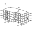
- FIG. 8 is a top view showing an example of the arrangement structure of various devices of the upper revolving body 3.
- FIG. FIG. 9 is a perspective view showing an example of the maintenance door 3D of the upper rotating body 3.
- the house portion 3H (see FIG. 9) of the upper revolving body 3 is omitted in order to expose various devices of the upper revolving body 3.
- FIG. 8 is a top view showing an example of the arrangement structure of various devices of the upper revolving body 3.
- FIG. 9 is a perspective view showing an example of the maintenance door 3D of the upper rotating body 3.
- the house portion 3H (see FIG. 9) of the upper revolving body 3 is omitted in order to expose various devices of the upper revolving body 3.
- FIG. 9 is a perspective view showing an example of the maintenance door 3D of the upper rotating body 3.
- the power storage device 19 is mounted on the right side of the upper swing body 3 in a range extending from the front part to the central part in the front-rear direction.
- a pump electric motor 12 , a main pump 14 , a pilot pump 15 , a control valve 17 , and an inverter 18 are provided in a range extending from the center portion in the left-right direction to the right end portion of the rear portion of the upper swing body 3 .
- the pump electric motor 12 and the inverter 18 are arranged integrally in the central portion in the left-right direction of the rear portion of the upper revolving body 3 .
- the pump electric motor 12 and the inverter 18 are arranged such that the rotating shaft of the pump electric motor 12 extends in the left-right direction and the output shaft extends rightward.
- the pump electric motor 12 is mounted on the bottom portion 3B (swing frame) of the upper swing body 3 via a mount member.
- the pump motor 12 may be arranged at a position relatively close to the bottom portion 3B so that the positions of the main pump 14 and the pilot pump 15, which are connected in a mechanically drivable manner, are as low as possible. .
- the position of the main pump 14 can be arranged lower than the liquid level inside the hydraulic oil tank T. As shown in FIG. Therefore, occurrence of air entrapment in the main pump 14 can be suppressed.
- the main pump 14 and the pilot pump 15 are arranged adjacent to the right side of the pump electric motor 12 with their input shafts connected to the output shaft of the pump electric motor 12 .
- the main pump 14 and the pilot pump 15 are mounted on the bottom portion 3 ⁇ /b>B via the pump electric motor 12 , for example, by being connected to the pump electric motor 12 .
- the control valve 17 is arranged at the center in the left-right direction of the rear part of the upper revolving body 3 and above the pump electric motor 12 .
- the pump motor 12 and the main pump 14 are arranged at a relatively low position in the space between the bottom portion 3B of the upper rotating body 3 and the housing portion 3H, and the control valve 17 is arranged at a relatively high position in that space. placed in position.
- a pedestal 17MT provided so as to straddle the pump electric motor 12 in the front-rear direction is attached to the bottom portion 3B.
- the control valve 17 is mounted on the base 17MT so as to be mounted on the bottom portion 3B via the base 17MT.
- the control valve 17 may be arranged above the main pump 14 and the pilot pump. Further, the control valve 17 may be arranged so as to straddle between the pump motor 12 and the main pump 14 or the pilot pump 15 in the left-right direction.
- a swing hydraulic motor 2A is mounted at the center of the upper swing body 3.
- a hydraulic oil tank T is arranged in a space in the longitudinal direction between the swing hydraulic motor 2A, the pump electric motor 12, and the control valve 17.
- the hydraulic oil tank T is mounted on the bottom portion 3B directly or via a bracket or the like.
- a radiator 62, a condenser 82B, and a fan 90 are arranged on the left side of the rear portion of the upper swing body 3, that is, on the left side of the pump electric motor 12, the main pump 14, and the control valve 17.
- the radiator 62 is arranged in a state of standing substantially perpendicular to the bottom portion 3B so that the front-rear direction is substantially the longitudinal direction (width direction) and the left-right direction is substantially the lateral direction (thickness direction).
- the word “substantially” means, for example, that manufacturing errors of the shovel 100 and equipment mounted on the shovel 100 are allowed. Hereinafter, it is used with the same intention.
- the radiator 62 can perform heat exchange by introducing air between the fins of the core and allowing the air to pass in the left-right direction (transverse direction).
- the radiator 62 is attached to the bottom portion 3B via a mounting member, for example.
- the capacitor 82B is arranged on the left side of the radiator 62 so as to be adjacent to it.
- a capacitor 82B is placed in series with the radiator 62 relative to the air flow. That is, like the radiator 62, the capacitor 82B is placed substantially vertically with respect to the bottom 3B so that the front-rear direction is substantially the longitudinal direction (width direction) and the left-right direction is the lateral direction (thickness direction). placed.
- the capacitor 82B is mounted on the bottom portion 3B via the radiator 62, for example, by being attached to the radiator 62 directly or via a bracket or the like.
- radiator 62 may be arranged adjacent to the radiator 62 and the condenser 82B.
- an oil cooler may be arranged on the left side of the radiator 62 and above or below the condenser 82B. This is because the vertical dimension of the capacitor 82B is generally smaller than the radiator 62 to some extent.
- the fan 90 is arranged on the right side of the radiator 62 so as to be adjacent to it.
- the fan 90 is mounted on the bottom portion 3B via the radiator 62 by being attached to the radiator 62 via a fan shroud made of resin, for example.
- the fans 90 are arranged, for example, in two rows in the longitudinal direction (front-rear direction) of the radiator 62 and in two stages in the height direction (up-down direction).
- the fan 90 blows air to the radiator 62, the condenser 82B, and the like in a mode in which air is sucked from the radiator 62 side (left side) to the right side.
- the fan 90 may be arranged adjacent to the left side of the condenser 82B, the radiator 62, and the like. In this case, the fan 90 blows air to the radiator 62, the condenser 82B, and the like in a manner that pushes air from the left side toward the condenser 82B and the radiator 62 (right side).
- a battery 46 and a compressor 82A are arranged at the left end of the rear portion of the upper revolving body 3, that is, to the left of the radiator 62, the condenser 82B, and the fan 90.
- the battery 46 is attached to the bottom portion 3B, for example, via a bracket or the like.
- the compressor 82A is arranged above the battery 46, for example, by being mounted on a frame rising from the bottom 3B.
- a charging port 72 is provided on the side surface of the cabin 10 of the upper swing body 3 .
- the charging ports 72A, 72 are arranged side by side, for example.
- a DC-DC converter 44 and an on-board charger 70 are arranged inside the cabin 10 .
- a maintenance door 3D is provided at the rear of the upper rotating body 3 (house portion 3H).
- the power storage device 19 having a relatively large size is arranged in the front right portion of the upper revolving body 3 , and the group of relatively small parts are concentrated in the rear portion of the upper revolving body 3 . Therefore, the operator can easily access these parts groups through the maintenance door 3D.
- the maintenance door 3D includes maintenance doors 3D1 to 3D3.
- the maintenance door 3D1 is provided in the left-right central portion of the rear portion of the housing portion 3H, and can be opened upward with the horizontal axis of the upper surface of the housing portion 3H as a fulcrum. Accordingly, the operator can access the pump motor 12, the control valve 17, the inverter 18, the hydraulic oil tank T, and the like through the opening of the maintenance door 3D1, and perform various maintenance. In particular, the operator can easily perform maintenance on hydraulic equipment such as the oil filter of the hydraulic oil tank T, for which the necessity and frequency of maintenance are relatively high.
- the maintenance door 3D2 is provided on the left end side surface of the rear part of the house part 3H, and can be opened leftward with the vertical axis of the side surface of the house part 3H as a fulcrum. Thereby, the operator can access the battery 46, the compressor 82A, the condenser 82B, the radiator 62, etc. through the opening of the maintenance door 3D2, and perform various maintenance.
- the maintenance door 3D3 is provided on the right end side surface of the rear part of the house part 3H, and can be opened leftward with the vertical axis of the side surface of the house part 3H as a fulcrum.
- the operator can access the main pump 14, the pilot pump 15, and nearby parts through the opening of the maintenance door 3D3 to perform various maintenance operations.
- the operator can easily perform maintenance on filters arranged in the vicinity of the main pump 14, for which the necessity and frequency of maintenance are relatively high.
- the rear portion of the upper revolving body 3 is configured to have a substantially arc shape centering on the revolving center (axis center) 3X when viewed from above.
- the turning radius of the rear portion of the upper turning body 3 can be made relatively small.
- the turning radius of the rear part of the upper revolving body 3 means the radius of the locus (outer edge) drawn by the rear part of the upper revolving body 3 when the upper revolving body 3 turns, centering on the turning center 3X.
- the excavator 100 corresponds to, for example, a minimal rear radius excavator.
- a rear ultra-short swing excavator means an excavator in which the ratio of the swing radius of the rear portion of the upper swing body 3 to half (1/2) of the full width of the crawler 1C is within 120%.
- the excavator 100 can improve workability in a narrow work site.
- the power storage device 19 which is one of the largest components mounted on the upper revolving body 3 , is arranged in the right front part of the upper revolving body 3 .
- the pump electric motor 12 and the main pump 14 are mounted on the rear portion of the upper revolving body 3 .
- the shovel 100 can relatively reduce the dead space by arranging the pump electric motor 12, the main pump 14, etc., which are relatively small in size, in the rear part of the upper revolving body 3.
- the excavator 100 can secure a relatively large installation space for the power storage device 19 along the right side surface of the upper revolving body 3, which has a small change in lateral position in the front-rear direction in top view. Therefore, the excavator 100 can realize an efficient arrangement structure of the components of the upper revolving body 3 including the power storage device 19 .
- the excavator 100 may be an excavator with a minimal rear swing radius in which the ratio of the turning radius of the rear portion of the upper turning body 3 to half the total width of the lower traveling body 1 is 120% or less.
- the upper revolving body 3 may have a substantially arcuate shape at its rear portion with reference to the revolving center 3X when viewed from above.
- the excavator 100 can realize a relatively small turning radius at the rear portion of the upper turning body 3 by an efficient arrangement structure including the power storage device 19 . Therefore, the excavator 100 can improve work efficiency in a narrow work site.
- control valve 17 is arranged on at least one of the main pump 14 and the pump electric motor 12 .
- the excavator 100 can secure a space above the main pump 14 and the pump electric motor 12, which are relatively small in height, as a space for arranging the control valve 17.
- the control valve 17 supplied from the main pump 14 is arranged at a position relatively close to the main pump 14, so that the hydraulic oil piping can be relatively shortened. Therefore, the excavator 100 can achieve a more efficient arrangement structure of the components in the upper revolving body 3 .
- the main pump 14 may be arranged below the liquid surface of the hydraulic oil in the hydraulic oil tank T.
- the excavator 100 can suppress the occurrence of air entrapment in the main pump 14 .
- the power storage device 19 may be arranged in a range extending from the front portion on the right side of the upper swing body 3 to the central portion on the right side in the front-rear direction.
- the main pump 14 may be arranged behind the power storage device 19 .
- the pump motor 12 may be arranged to the left of the main pump 14 so as to mechanically drive the main pump 14 .
- the excavator 100 secures a relatively large capacity of the power storage device 19 , and disposes the main pump 14 having a relatively small size behind the power storage device 19 .
- the dimension in the front-rear direction at the right corner (right end) can be kept small. Therefore, the excavator 100 can ensure both the capacity of the power storage device 19 and the reduction in the turning radius of the rear portion of the upper turning body 3 .
- the hydraulic oil tank T may be arranged in front of the pump electric motor 12 and to the left of the power storage device 19 .
- the space in front of the pump electric motor 12 and the power storage device 19 can be used to specifically arrange the hydraulic oil tank T and secure its capacity.
- the radiator 62 may be arranged to the left of the pump electric motor 12 .
- the radiator 62 can be specifically arranged using the space on the left side of the rear portion of the upper revolving body 3 .
- a maintenance door 3D that allows access to the components mounted on the upper revolving body 3 may be provided at the rear portion of the housing portion 3H of the upper revolving body 3 .
- the operator can easily access a group of parts relatively small compared to the power storage device 19, which are collectively arranged at the rear portion of the upper rotating body 3, as described above.
- FIG. 10 Details of the power storage device 19 will be described with reference to FIGS. 10 to 13.
- FIG. 10 Details of the power storage device 19 will be described with reference to FIGS. 10 to 13.
- FIG. 10 and 11 are perspective views showing one example and another example of a power storage device.
- FIG. 12 is an exploded view showing an example of the configuration of the power storage module 19MD.
- FIG. 13 shows an example of a connection structure between power storage modules.
- the power storage device 19 is configured by vertically stacking a plurality of power storage modules 19MD and connecting vertically adjacent power storage modules with wire harnesses 19C.
- a plurality of power storage modules 19MD are connected in series, and one positive terminal and the other negative terminal of vertically adjacent power storage modules 19MD are connected by one wire harness 19C.
- the power storage modules 19MD that are vertically adjacent to the object of parallel connection have two wires connecting their positive terminals and negative terminals. It may be connected by harness 19C.
- the power storage device 19 is mounted on the bottom portion 3B (swing frame) of the upper swing body 3 via a mount member 19MT attached to the power storage module 19MD on the bottom layer.
- the power storage module 19MD includes a plurality (eight in this example) of battery modules BMD, a battery management unit 19MU, a housing 19H, a service plug installation section 19SH, and a cover 19CV. .
- a battery module BMD is an assembly configured by connecting a plurality of battery cells in series.
- the battery management unit BMU communicates with various sensors built into the power storage module 19MD, sequentially acquires detection data thereof, communicates with the upper controller 30D, and transmits the detection data to the controller 30D.
- Various sensors are voltage sensors, current sensors, temperature sensors, and the like. Thereby, the controller 30D can monitor the state of the battery module BMD and the state of each battery cell included in the battery module BMD.
- the housing 19H accommodates therein components of the power storage module 19MD such as a plurality of battery modules BMD and a battery management unit BMU.
- the housing 19H is made of, for example, metal such as aluminum alloy or iron.
- the housing 19H includes an accommodating portion 19H1 that accommodates components, and a lid portion 19H2 that seals an upper opening of the accommodating portion 19H1.
- the lid portion 19H2 is vertically fastened with bolts BLT1 (see FIG. 13) to a flange FL (see FIG. 13) provided on the outer edge of the opening of the housing portion 19H1.
- Each of the plurality of power storage modules 19MD has a housing 19H with substantially the same shape. As a result, a plurality of power storage modules 19MD can be easily stacked in the vertical direction by having substantially the same shape when viewed from above.
- housings 19H of the plurality of power storage modules 19MD may have substantially the same basic shape manufactured by forging or casting, and may have some differences in additional processing.
- the power storage module 19MD in the lowest layer among the plurality of power storage modules 19MD may be processed exclusively for connection with the mount member 19MT.
- some housings 19H of the plurality of power storage modules 19MD may be subjected to special processing for attaching brackets for supporting other parts when mounted on the upper revolving body 3.
- the service plug installation portion 19SH is a hole for installing a service plug for interrupting the electrical connection state of the plurality of battery modules BMD included in the power storage module 19MD.
- the service plug installation portion 19SH is provided on the side surface of the housing 19H (on the accommodation portion 19H1).
- the cover 19CV is detachably attached to the side surface of the housing 19H (accommodating portion 19H1) so as to cover the service plug installation portion 19SH, that is, the service plug. Thereby, the cover 19CV can protect the service plug. Further, the cover 19CV has a structure such that the cover 19CV cannot be attached to the housing 19H (receiving portion 19H1) when the service plug is not completely attached to the service plug installation portion 19SH (for example, in a half-fitted state). As a result, it is possible to prevent a situation in which the cover 19CV is closed due to human error while the service plug is not properly installed.
- devices related to the power storage device 19 may be dispersedly built in the plurality of power storage modules 19MD.
- Related devices include, for example, a controller 30D and a junction box.
- the junction box relays power between the power storage device 19 and a plurality of other devices (eg, inverter 18, DC-DC converter 44, vehicle charger 70, charging port 72B, etc.).
- the controller 30D is housed in the housing 19H of any one of the plurality of power storage modules 19MD, and the junction box is housed in the housing 19H of another power storage module 19MD. may be accommodated.
- devices related to the power storage device 19 can be accommodated using the empty space of each of the plurality of power storage modules 19MD.
- the housings 19H of the vertically adjacent power storage modules 19MD are directly connected in the vertical direction.
- a rib RB1 that circulates so as to extend along the outer edge in a top view is provided at the lower end of the side surface of the housing portion 19H1.
- Ribs RB2 are provided at predetermined intervals along the outer edge in a top view in a height direction range between the rib RB1 at the lower end and the flange FL at the upper end on the side surface of the accommodation portion 19H1.
- a fastening hole FH11 is provided at a location where the rib RB2 is connected to the flange FL of the accommodating portion 19H1, and a fastening hole FH12 is provided at a corresponding position of the top view lid portion 19H2.
- a sealing member is provided between the rear surface of the lid portion 19H2 and the flange FL of the accommodating portion 19H1 to ensure airtightness.
- a recess RC is provided on the lower surface of the rib RB1 of the housing portion 19H1.
- the recess RC has a bolt so that the head of the BLT1 can be accommodated when the housing 19H (receiving portion 19H1) is stacked on the housing 19H (cover portion 19H2) of the power storage module 19MD adjacent below.
- the same number as the number of BLT1 are arranged.
- the head of the bolt BLT1 on the upper surface of the housing 19H of the lower power storage module 19MD is positioned between the housing 19H (receiving portion 19H1) of the upper power storage module 19MD. It is possible to prevent contact with the lower surface. Therefore, it is possible to avoid damage to the bolt BLT1 and increase in the dimension of the power storage device 19 in the height direction by the head portion of the bolt BLT1.
- a plurality of fastening holes FH21 penetrating from the upper surface to the lower surface are provided in the rib RB1 of the housing portion 19H1.
- a plurality of fastening holes FH21 are arranged between two adjacent ribs RB2 on the outer edge of the housing portion 19H1 in top view.
- a plurality of fastening holes FH22 penetrating from the upper surface to the lower surface are provided in the flange FL of the accommodating portion 19H1.
- the plurality of fastening holes FH22 are provided at substantially the same positions as the fastening holes FH21 in top view.
- a plurality of fastening holes FH23 penetrating from the upper surface to the lower surface are provided in the lid portion 19H2.
- the plurality of fastening holes FH23 are provided at substantially the same positions as the fastening holes FH21 and FH22 in top view in a state where the housing portion 19H1 and the lid portion 19H2 are connected.
- the bolt BLT2 is inserted from above into the fastening hole FH21 of the upper power storage module 19MD (housing 19H) and the fastening holes FH22 and FH23 of the lower power storage module 19MD (housing 19H). Two power storage modules 19MD can be connected.
- the power storage device 19 is configured by vertically stacking a plurality of power storage modules 19MD.
- the casings 19H of the vertically adjacent power storage modules 19MD are connected to each other.
- a plurality of power storage modules 19MD can be mounted on the upper revolving body 3 via the power storage module 19MD in the lowest layer simply by connecting the housings 19H of the power storage modules 19MD that are vertically adjacent to each other. Therefore, for example, when changing the number of power storage modules 19MD according to the specifications of the excavator 100, as in the case of FIGS. 10 and 11, the number of power storage modules 19MD can be easily changed. Therefore, the capacity of power storage device 19 can be easily changed.
- each of the plurality of power storage modules 19MD has an upper connection structure (for example, a fastening hole FH22) so as to match the lower connection structure (for example, a fastening hole FH21) of all the other power storage modules 19MD. , FH23) may be configured.
- each of the plurality of power storage modules 19MD has a lower connection structure (for example, fastening holes FH21) so as to match the upper connection structures (for example, fastening holes FH22 and FH23) of all other power storage modules 19MD. may be configured.
- the plurality of power storage modules 19MD can be stacked and connected in any order, so that the plurality of power storage modules 19MD can be stacked and mounted on the upper revolving body 3 more easily. Therefore, the number of power storage modules 19MD can be changed more easily.
- the plurality of power storage modules 19MD may have substantially the same shape when viewed from above.
- the plurality of power storage modules 19MD can be stacked in any order, so that the plurality of power storage modules 19MD can be stacked and mounted on the upper revolving body 3 more easily. Therefore, the number of power storage modules 19MD can be changed more easily.
- At least two or more of the plurality of power storage modules 19MD may have substantially the same outer shape of the housings 19H.
- the plurality of power storage modules 19MD can be stacked in any order, so that the plurality of power storage modules 19MD can be stacked and mounted on the upper revolving body 3 more easily. Therefore, the number of power storage modules 19MD can be changed more easily.
- devices related to the power storage device 19 may be dispersedly built in the housings 19H of the plurality of power storage modules 19MD.
- the related device may include at least one of a controller 30D that controls the power storage device 19 and a junction box that relays power between the power storage device 19 and a plurality of other devices. .
- the controller 30D and the junction box can be distributed and built in the housings 19H of the plurality of power storage modules 19MD.
- the plurality of power storage modules 19MD each include a service plug installation portion 19SH to which a service plug that cuts off an electric power path is detachably attached to the side surface of the housing 19H, and a cover 19CV that covers the service plug installation portion 19SH.
- the housing 19H includes a housing portion 19H1 that houses the battery module BMD and has an open top, a lid portion 19H2 that closes the open top portion of the housing portion 19H1, and the lid portion 19H2 to the housing portion 19H1. It may include a plurality of bolts BLT1 that fasten in the vertical direction. Moreover, the housings 19H of the vertically adjacent power storage modules 19MD may be connected by a plurality of bolts BLT2 that are fastened in the vertical direction. In the housing 19H, fastening holes FH21, FH22, FH23 for fastening the bolts BLT2 may be provided between fastening holes FH11, FH12 for fastening two adjacent bolts BLT1.
- connection structure that connects the casings 19H of the vertically adjacent power storage modules 19MD is arranged near the connection structure of the housing portion 19H1 and the lid portion 19H2 of the casing 19H. It is possible to avoid a situation in which the outer edge of the Therefore, it is possible to achieve both the connecting structure of the housing portion 19H1 and the lid portion 19H2 of the housing 19H and the connecting structure of connecting the housings 19H of the vertically adjacent power storage modules 19MD in a smaller space.
- the housing 19H has a recess RC on its lower surface at substantially the same position as the bolt BLT1 of the housing 19H when stacked on the housing 19H of the other power storage module 19MD. good.
- the head of the bolt BLT1 can be accommodated in the recess RC. Therefore, it is possible to avoid a situation in which the head of the bolt BLT1 of the lower housing 19H contacts the lower surface of the upper housing 19H. Therefore, it is possible to suppress the occurrence of damage to the head of the bolt BLT1 and an increase in the vertical dimension of the power storage device 19 due to the head of the bolt BLT1.
- FIG. 14 is a diagram for explaining a switching method between operation and stop of the DC-DC converters 44A and 44B.
- FIG. 15 is a diagram showing the conversion efficiency of the DC-DC converter 44. As shown in FIG.
- the scale interval of the current consumption has no meaning, and merely represents the magnitude relationship between the threshold values I1 and I2 and the maximum value Imax in a simulated manner.
- the DC-DC converters 44A and 44B differ from each other in current capacity, that is, the maximum value of current that can be output.
- the DC-DC converter 44A is configured to have a relatively small current capacity
- the DC-DC converter 44B is configured to have a relatively large current.
- the controller 30E operates and operates the DC-DC converters 44A and 44B in accordance with the current required by the entire low-voltage equipment, that is, the current consumption of the entire low-voltage equipment. Toggle stop. Based on the output of the sensor 48, the controller 30E can acquire the current consumption of the entire low-voltage equipment.
- the controller 30E operates the DC-DC converter 44A and stops the DC-DC converter 44B when the current consumption of the entire low-voltage device is equal to or less than the threshold I1 (>0).
- the threshold I1 is set as a value somewhat smaller than the maximum value of current that can be output from the DC-DC converter 44A.
- the controller 30E causes the DC-DC converter 44A, which has a relatively small current capacity, to supply power to the battery 46 and the low-voltage equipment when the current consumption of the entire low-voltage equipment is equal to or less than the threshold value I1.
- the controller 30E stops the DC-DC converter 44A and operates the DC-DC converter 44B.
- the threshold I2 is set as a value somewhat smaller than the maximum value of current that can be output from the DC-DC converter 44B. That is, the controller 30E supplies power to the battery 46 and low-voltage equipment only with the DC-DC converter 44B having a relatively large current capacity when the current consumption of the entire low-voltage equipment is greater than the threshold I1 and equal to or less than the threshold I2. supply.
- both the DC-DC converters 44A and 44B are instantaneously stopped when the current consumption of the entire low-voltage equipment changes from below the threshold I1 to above the threshold I1, or vice versa. situations can arise. However, since the battery 46 functions as a buffer, problems such as momentary interruption of power supply to low-voltage devices do not occur.
- the controller 30E operates both the DC-DC converters 44A and 44B when the current consumption of the entire low-voltage device is greater than the threshold value I2 and equal to or less than the maximum value Imax. In other words, the controller 30E causes both the DC-DC converters 44A and 44B to supply power to the battery 46 and the low voltage equipment in a range where the current consumption of the entire low voltage equipment is greater than the threshold value I2.
- Hysteresis is provided in the operation/stop switching method of the DC-DC converters 44A and 44B depending on whether the consumption current of the entire low-voltage device rises or falls, and the threshold I1 and the threshold I2 are different. Different values may be set in different cases.
- the conversion efficiency of the DC-DC converter 44A is higher than the conversion efficiency of the DC-DC converter 44B (graph 1502A) in the range where the output current is equal to or lower than the threshold I1. This is because the smaller the current capacity, the better the rise of the conversion efficiency with respect to the increase in the output current. Therefore, in the range where the current consumption of the entire low-voltage device is equal to or less than the threshold value I1, the conversion efficiency of the entire DC-DC converter 44 can be relatively increased by operating only the DC-DC converter 44A.
- the conversion efficiency of the DC-DC converter 44B maintains a relatively high state in the range where the output current is greater than the threshold I1 and equal to or less than the threshold I2 (see graph 1502).
- the conversion efficiency of the DC-DC converter 44A slightly decreases because it is close to the upper limit of the output current (see graph 1501A). Therefore, in the range where the current consumption of the entire low-voltage device is greater than the threshold I1 and equal to or less than the threshold I2, only the DC-DC converter 44B is operated to relatively increase the conversion efficiency of the entire DC-DC converter 44. can be done.
- the DC-DC converter 44B alone cannot cover the current consumption of the entire low-voltage device. Therefore, in a range where the current consumption of the entire low-voltage device is greater than the threshold value I2, the current consumption of the entire low-voltage device can be covered by operating the DC-DC converter 44A in addition to the DC-DC converter 44B. In this case, since the output current of the DC-DC converter 44B is maintained relatively high, the conversion efficiency of the DC-DC converter 44B is maintained relatively high (see graph 1503).
- the DC-DC converter 44A is maintained at relatively high conversion efficiency (see graph 1504) by appropriately controlling the output current, removing the region of relatively low conversion efficiency (graph 1504A). . Thereby, the conversion efficiency of the DC-DC converter 44 as a whole can be made relatively high.
- the excavator 100 uses a plurality of DC-DC converters 44A and 44B connected in parallel to supply power to low-voltage equipment and the battery 46.
- the rising of the individual output currents of the DC-DC converters 44A and 44B can be made relatively faster. Therefore, the conversion efficiency of the entire DC-DC converter 44 can be made relatively high. Therefore, the power consumption of the power storage device 19 can be suppressed, and the operation time of the shovel 100 can be relatively lengthened.
- the current capacities of the DC-DC converters 44A and 44B are set to be different from each other.
- the controller 30E switches between operating and stopping the DC-DC converters 44A and 44B according to the current consumption of the entire low-voltage device.
- Restrictions on the power supply from the DC-DC converter 44 to the battery 46 and low-voltage devices include, for example, stopping the power supply.
- the restriction of the power supply from the DC-DC converter 44 to the battery 46 and low-voltage equipment includes, for example, stopping the power supply from either one of the DC-DC 44A, 44B to the battery 46 or low-voltage equipment, That is, a limitation of the current that can be supplied by the entire DC-DC converter 44 is included. Stopping power supply from the DC-DC converter 44 to the battery 46 or low-voltage equipment includes, for example, stopping power supply due to an abnormality in the DC-DC converter 44 .
- Abnormalities in the DC-DC converter 44 include, for example, an input overvoltage in which the input voltage from the power storage device 19 exceeds (exceeds) a predetermined range and an input low voltage in which the input voltage falls below a predetermined range.
- Abnormalities of the DC-DC converter 44 include, for example, an output overvoltage in which the output voltage to the battery 46 or low-voltage equipment exceeds (exceeds) a predetermined range, and an output low voltage in which the output voltage falls below a predetermined range.
- the abnormality of the DC-DC converter 44 includes, for example, a short circuit of the circuit of the DC-DC converter 44 .
- Abnormality of the DC-DC converter 44 includes, for example, overcurrent.
- Abnormality of the DC-DC converter 44 includes, for example, overheating in which the temperature of a predetermined portion thereof exceeds (exceeds) a predetermined range. Abnormalities in the DC-DC converter 44 include abnormal communication with the outside such as the controller 30E. Abnormality of the DC-DC converter 44 includes, for example, excessive power supply voltage exceeding (exceeding) a predetermined range and insufficient power supply voltage falling below a predetermined range. Stopping the power supply from the DC-DC converter 44 to the battery 46 or low-voltage equipment includes, for example, temporary output limitation due to transition of the DC-DC converter 44 to the protection mode.
- FIG. 16 is a flowchart schematically showing a first example of control processing when power supply from DC-DC converter 44 is restricted.
- FIG. 17 is a diagram showing an example of changes in the voltage of battery 46 when power supply from DC-DC converter 44 is restricted.
- This flowchart starts when the power supply from the DC-DC converter 44 to the battery 46 and low-voltage equipment is restricted. Specifically, when the power supply from the DC-DC converter 44 is restricted or when the power supply from the DC-DC converter 44 is restricted due to an abnormality or the like, the controller 30E outputs a signal to that effect. It may be sent to the controller 30A. Then, when the controller 30A receives the signal, the controller 30A may start this flowchart. The same may be applied to the flow charts of FIGS. 18 to 20, which will be described later.
- step S102 the controller 30A reduces the current consumption of the low-voltage equipment by restricting the operation of the low-voltage equipment.
- the controllers 30A to 30E can operate only with the power of the battery 46. time can be relatively long.
- the controller 30A can relatively lengthen the operable time of various devices of the excavator 100 other than the low-voltage devices whose operation is restricted, and relatively lengthen the operable time of the excavator 100. .
- the controller 30A may notify the user through the output device 50 that the operation of the low-voltage equipment is restricted after the process of step S102. Further, when the excavator 100 is remotely operated or remotely monitored, the controller 30A may transmit a notification signal indicating that the operation of the low-voltage equipment is restricted to the external device through the communication device.
- Restrictions on the operation of low-voltage equipment include, for example, stopping the operation of low-voltage equipment. As a result, the current consumption of the target low-voltage equipment can be reduced to substantially zero. Further, the operation limitation of the low-voltage equipment includes a state in which the low-voltage equipment continues to operate under relatively low performance (hereinafter referred to as "performance-limited state"). As a result, the current consumption of the target low-voltage device can be reduced more than in the case of operating conditions in which the performance of the target low-voltage device is relatively high.
- the low-voltage equipment whose current consumption is to be reduced is a low-voltage equipment that consumes relatively large current.
- Low voltage equipment of interest includes, for example, water pump 64 .
- the performance-restricted state of the water pump 64 includes, for example, a state in which the discharge flow rate of the water pump 64 is restricted to be relatively smaller (lower) than normal.
- the target low-voltage equipment includes, for example, the fan 90 .
- the performance limited state of the fan 90 includes, for example, a state in which the rotational speed of the fan 90 is limited to be relatively smaller (lower) than normal.
- the target low-voltage equipment includes the air conditioner 80, for example.
- the performance-restricted state of the air conditioner 80 includes, for example, an operating state in which the set temperature of the air conditioner 80 is restricted to be relatively high in a situation where the set temperature of the air conditioner 80 is lower than the outside air temperature (for example, summer).
- the performance-restricted state of the air conditioner 80 includes, for example, an operating state in which the set temperature of the air conditioner 80 is relatively low in a situation where the set temperature of the air conditioner 80 is higher than the outside air temperature (for example, winter).
- the refrigerant circuit 66 is filled with a relatively large capacity refrigerant. Therefore, even when the operation of the water pump 64 and the fan 90 is restricted, the heat to be cooled moves to the refrigerant circuit 66 . Therefore, although the cooling performance is degraded, the cooling device 60 can continue cooling the object to be cooled even when the operation of the water pump 64 and the fan 90 is restricted.
- step S102 the controller 30A may stop the operation of the target low-voltage device, shift the operation of the target low-voltage device to the performance limited state, or cause the target low-voltage device to operate It is also possible to selectively use the stop of the operation and the transition to the performance limited state.
- the controller 30A may determine whether to stop the operation of the target low-voltage device or put it in a performance-limited state.
- the voltage of battery 46 can be grasped based on the output of sensor 48 .
- the controller 30A sets the operation of the target low-voltage device to the performance-limited state, and when the voltage of the battery 46 is relatively low, the target low-voltage device The operation may be stopped.
- the controller 30A may limit the operation of all target low-voltage devices such as the water pump 64, the fan 90, and the air conditioner 80, or limit the operation of some of them.
- the controller 30A restricts the operation of all target low-voltage devices such as the water pump 64, the fan 90, and the air conditioner 80, and restricts the operation of some target low-voltage devices. It may be used separately from when performing
- the controller 30A may change the number of low-voltage devices subject to operation restriction according to the voltage of the battery 46. Specifically, the controller 30A may increase the number of low-voltage devices whose operation is restricted as the voltage of the battery 46 decreases. In this case, the controller 30 ⁇ /b>A may preferentially limit the operation of the water pump 64 and the fan 90 over the air conditioner 80 . Further, when the fan 90 for blowing air from the condenser 82B and the fan 90 for blowing air from the radiator 62 are provided separately, the controller 30A may preferentially limit the operation of the latter fan 90 over the former fan 90. good.
- step S102 the controller 30A proceeds to step S104.
- step S104 the controller 30A determines whether or not the DC-DC converter 44 has recovered from the operation-restricted state to the normal operating state. If the DC-DC converter 44 has returned to the normal operating state, the controller 30A proceeds to step S106; otherwise, repeats the processing of this step until the normal operating state is restored.
- step S106 the controller 30A cancels the operation restriction of the target low-voltage equipment.
- the controller 30A may notify the user through the output device 50 that the operation restriction of the target low-voltage device is to be released in conjunction with releasing the operation restriction of the target low-voltage device. Further, when the excavator 100 is remotely operated or remotely monitored, the controller 30A may transmit a notification signal to the external device to the effect that the operation restriction of the target low-voltage equipment is lifted through the communication device. The same applies to step S204 of the second example (FIG. 18), step S302 of the third example (FIG. 19), and step S402 of the fourth example (FIG. 20).
- step S106 the controller 30A ends the process of this flowchart.
- steps S104 and S106 may be omitted.
- the voltage of the battery 46 drops.
- the power consumption of the controllers 30B and 30D of the electric drive system and the power supply system, and the power consumption of the cooling system such as the water pump 64 and the fan 90 are relatively high compared to the normal hydraulic excavator. , and the voltage drop due to the internal resistance becomes significant. Therefore, in a situation where the operation limitation of the DC-DC converter 44 is not lifted, the voltage of the battery 46 drops sharply if the operation limitation of the low-voltage equipment is not performed.
- the control power supply of various controllers such as the controllers 30A to 30E included in the control device 30 immediately reaches the lower limit value, and the various controllers stop (see broken lines in the figure).
- the excavator 100 is forcibly stopped. Therefore, when the power supply from the DC-DC converter 44 to the battery 46 or low-voltage equipment is restricted, depending on the situation, the excavator 100 may be evacuated to a safe place or the excavator 100 may be moved for repair. may become impossible.
- the controller 30A limits the operation of the low-voltage equipment.
- the current consumption of the low-voltage equipment decreases, the voltage drop due to the internal resistance decreases, the voltage recovers, and the voltage drop of the battery 46 also moderates due to the decrease in the current consumption (see the solid line in the figure). ).
- the excavator 100 is forcibly stopped. Therefore, the user can operate the excavator 100 to evacuate the excavator 100 to a safe place or move the excavator 100 for repair.
- the excavator 100 when the excavator 100 operates with the fully automatic operation function, the excavator 100 automatically evacuates the excavator 100 to a safe place or automatically moves the excavator 100 for repair, for example, in a predetermined evacuation mode. You can let
- the controller 30A limits the operation of the target low voltage load to reduce power consumption.
- the controller 30A can suppress the voltage drop of the battery 46 when the power supply from the DC-DC converter 44 is restricted, and ensure a relatively long time until the various controllers stop. Therefore, the excavator 100 can evacuate the excavator 100 (own machine) to a safe place or move the excavator 100 (own machine) for repair by the operation of the operator or the automatic operation function.
- the case where the power supply from the DC-DC converter 44 to the battery 46 is restricted may include the case where the DC-DC converter 44 has an abnormality.
- the abnormality of the DC-DC converter 44 includes at least one of input overvoltage, input undervoltage, output overvoltage, output undervoltage, short circuit, overcurrent, overheating, excessive power supply voltage, insufficient power supply voltage, and communication abnormality. may be included.
- the controller 30A can suppress the voltage drop of the battery 46 and ensure a relatively long time until the various controllers stop when there is an abnormality in the DC-DC converter 44.
- the power supply from the DC-DC converter 44 to the battery 46 when the power supply from the DC-DC converter 44 to the battery 46 is restricted, the power supply from at least one of the plurality of DC-DC converters 44A, 44B to the battery 46 is stopped. may be included.
- the controller 30A suppresses the voltage drop of the battery 46 when, for example, the power supply from one of the DC-DC converters 44A and 44B is stopped, and the time until the various controllers stop is relatively long. can be secured for a long time.
- the low-voltage load whose operation is to be restricted may include at least one of the water pump 64 and the fan 90 .
- the controller 30A can limit the operation of the water pump 64 and the fan 90, which consume relatively large current, and specifically reduce the current consumption of the low-voltage equipment.
- the low-voltage load subject to operation restriction may include the air conditioner 80 .
- the controller 30A can restrict the operation of the air conditioner 80, which consumes relatively large current, and specifically reduce the current consumption of the entire low-voltage equipment.
- controller 30A may preferentially limit the operation of the water pump 64 and the fan 90 over the operation of the air conditioner 80.
- the controller 30A can reduce the current consumption of the entire low-voltage equipment while considering the comfort and health of the user (operator) of the cabin 10, for example.
- FIG. 18 is a flowchart schematically showing a second example of control processing when power supply from DC-DC converter 44 is restricted.
- the controller 30A outputs a control command to the controller 30B to limit the output of the pump motor 12.
- the controller 30A may limit the output of the pump motor 12 by controlling a regulator (not shown) to reduce the displacement of the variable displacement main pump 14 to reduce the load.
- the controller 30A may limit the output of the pump electric motor 12 by reducing the rotation speed of the pump electric motor 12 .
- the controller 30A may limit the output of the pump electric motor 12 by implementing both of these. As a result, it is possible to suppress the heat generation of the devices of the electric drive system and the power supply system, and reduce the load on the cooling device 60 .
- step S202 the controller 30A proceeds to step S204.
- the controller 30A reduces the current consumption of the low voltage equipment by restricting the operation of the low voltage equipment including the water pump 64 and the fan 90.
- the controller 30A can relatively lengthen the time during which the controllers 30A to 30E can operate only with the electric power of the battery 46, as in the case of the first example described above.
- steps S206 and S208 are the same as that of steps S104 and S106 in FIG. 16, so description thereof will be omitted.
- step S208 the controller 30A ends the process of this flowchart.
- the controller 30A limits the output of the pump motor 12 when limiting the operation of at least one of the water pump 64 and the fan 90.
- the controller 30A can suppress heat generation from the electric drive system and the power supply system by limiting the output of the pump motor 12. Therefore, even when the operation of the water pump 64 and the fan 90 is restricted, the controller 30A can suppress the temperature rise (overheat) of the equipment to be cooled by the cooling device 60 .
- the controller 30A grasps the temperature state of the device to be cooled based on the output of the temperature sensor 54, and limits the output of the pump motor 12 according to the temperature state of the device to be cooled by the cooling device 60. good too. Specifically, the controller 30A may limit the output of the pump motor 12 when the temperature of the device to be cooled by the cooling device 60 exceeds a predetermined threshold.
- FIG. 19 is a flowchart schematically showing a third example of control processing when power supply from DC-DC converter 44 is restricted.
- step S302 the controller 30A restricts the operation of at least one of the water pump 64 and the fan 90. As a result, the current consumption of the entire low-voltage device can be reduced.
- step S302 When the processing of step S302 is completed, the controller 30A proceeds to step S304.
- step S304 the controller 30A determines whether or not the DC-DC converter 44 has recovered from the operation-restricted state to the normal operating state. If the DC-DC converter 44 has not returned to the normal operating state, the controller 30A proceeds to step S306, otherwise proceeds to step S316.
- step S306 based on the output of the temperature sensor 54, the controller 30A determines whether the temperature of the device to be cooled by the cooling device 60 exceeds the threshold T11th (>0). If the temperature of the device to be cooled exceeds the threshold T11th, the controller 30A proceeds to step S308, otherwise returns to step S304.
- the controller 30A temporarily cancels the operation restriction of the water pump 64 and fan 90, which was restricted at step S302. Thereby, the cooling performance of the cooling device 60 can be improved, and the temperature rise of the device to be cooled can be suppressed.
- step S308 the controller 30A proceeds to step S310.
- step S310 the controller 30A determines whether or not the DC-DC converter 44 has recovered from the operation-restricted state to the normal operating state. If the DC-DC converter 44 has returned to the normal operating state, the controller 30A proceeds to step S316, otherwise proceeds to step S312.
- the controller 30A determines whether or not the temperature of the device to be cooled by the cooling device 60 is equal to or lower than the threshold value T12th ( ⁇ T11th). If the temperature of the device to be cooled is equal to or lower than the threshold T12th, the controller 30A proceeds to step S314; otherwise, returns to step S310.
- step S314 the controller 30A resumes the operation restriction of the water pump 64 and fan 90 that was temporarily released at step S308.
- step S314 When the process of step S314 is completed, the controller 30A returns to step S304.
- step S316 the controller 30A releases the operation restriction of the target low-voltage equipment.
- step S316 the controller 30A ends the process of this flowchart.
- the controller 30A can suppress the temperature rise of the device to be cooled while suppressing the current consumption of the entire low-voltage device.
- FIG. 20 is a flowchart schematically showing a fourth example of control processing when power supply from DC-DC converter 44 is restricted.
- this example represents control processing in a situation where the set temperature of the air conditioner 80 is lower than the outside air temperature (for example, in summer).
- the controller 30A limits the operation of the air conditioner 80 in step S402. As a result, the current consumption of the entire low-voltage device can be reduced.
- step S402 When the processing of step S402 is completed, the controller 30A proceeds to step S404.
- step S404 the controller 30A determines whether or not the DC-DC converter 44 has recovered from the operation-restricted state to the normal operating state. If the DC-DC converter 44 has not returned to the normal operating state, the controller 30A proceeds to step S406, otherwise proceeds to step S416.
- step S406 the controller 30A determines whether the indoor temperature of the cabin 10 exceeds the threshold T21th (>0) based on the output of the temperature sensor 56. If the temperature of the device to be cooled exceeds the threshold T21th, the controller 30A proceeds to step S408, otherwise returns to step S404.
- the controller 30A temporarily cancels the operation restriction of the air conditioner 80 that was restricted at step S402. As a result, the performance of the air conditioner 80 can be enhanced, and an increase in the indoor temperature of the cabin 10 can be suppressed.
- step S408 the controller 30A proceeds to step S410.
- step S410 the controller 30A determines whether or not the DC-DC converter 44 has returned from the operation-restricted state to the normal operating state. If the DC-DC converter 44 has returned to the normal operating state, the controller 30A proceeds to step S416, otherwise proceeds to step S412.
- the controller 30A determines whether or not the room temperature of the cabin 10 is equal to or lower than the threshold value T22th ( ⁇ T11th). If the temperature of the device to be cooled is equal to or lower than the threshold value T22th, the controller 30A proceeds to step S414; otherwise, returns to step S410.
- step S414 the controller 30A resumes the operation limitation of the air conditioner 80 that was temporarily released at step S408.
- step S414 When the processing of step S414 is completed, the controller 30A returns to step S404.
- step S416 the controller 30A releases the operation restriction of the target low-voltage equipment.
- step S416 the controller 30A ends the process of this flowchart.
- the controller 30A restricts the operation of the air conditioner 80. Temporarily removes restrictions on the operation of
- the controller 30A can prevent the indoor temperature of the cabin 10 from becoming too hot in the summer and too cold in the winter while suppressing the current consumption of the entire low-voltage equipment.
- FIG. 21 is a flow chart that schematically shows control processing for starting and stopping the operation mode of the excavator 100.
- FIG. FIG. 22 is a flowchart schematically showing an example of emergency stop processing of the excavator 100. As shown in FIG.
- the flowchart of FIG. 21 starts when a key switch is turned on in response to a predetermined input from the user through the input device 52.
- a key switch is provided in the power system between the battery 46 and various controllers such as the controllers 30A to 30E.
- step S502 the controller 30A performs operation mode start-up processing, which corresponds to initial processing when the excavator 100 is started.
- the operation mode is a default control mode during operation (during operation) of the excavator 100 for performing normal work by operating the actuator according to the operator's operation or an operation command corresponding to the automatic operation function.
- step S502 When the processing of step S502 is completed, the controller 30A proceeds to step S504.
- step S504 the controller 30A shifts to an operation mode corresponding to normal operation of the excavator 100.
- step S504 the controller 30A proceeds to step S506.
- step S506 the controller 30A determines whether or not the key switch has been turned on. If the key switch is turned on, the controller 30A proceeds to step S508, and if the key switch is not turned on, the controller 30A proceeds to step S510.
- the controller 30A performs the operation mode shutdown process corresponding to the termination process when the excavator 100 is stopped.
- step S508 the controller 30A ends the process of this flowchart.
- step S510 the controller 30A determines whether or not the charging port 72 is connected to the charging cable extending from the external power source. For example, when the charging cable is connected to the charging port 72A, the vehicle-mounted charger 70 transmits a signal indicating that the charging cable is connected to the charging port 72A to the controller 30D. Accordingly, the controller 30A can recognize that the charging cable has been connected to the charging port 72A by recognizing the reception of the signal from the vehicle-mounted charger 70 through the controller 30D. Further, for example, when the charging cable is connected to the charging port 72B, the controller 30D grasps the state in which the charging cable is connected to the charging port 72B by contact detection, communication with the charging stand side through power line communication, or the like.
- controller 30A can recognize through the controller 30D that the charging cable is connected to the charging port 72B. Controller 30A proceeds to step S512 when a charging cable extending from an external power source is connected to charging port 72, and returns to step S506 when the charging cable is not connected.
- step S512 emergency stop processing of the excavator 100 is performed. Specifically, the flow shifts to the flowchart of FIG. 22 .
- FIG. 22 is a flowchart of emergency stop processing when a charging cable is connected to the charging port 72A.
- step S602 the controller 30A notifies the user through the output device 50 that the excavator 100 will be stopped in an emergency together with the reason.
- the controller 30A may also notify that the key switch must be turned off once in order to recover from the emergency stop state of the excavator 100 (see step S620).
- the controller 30A may transmit a signal indicating that the excavator 100 is to be stopped in an emergency to the external device through the communication device.
- the controller 30A proceeds to step S604 when the process of step S602 is completed and a certain period of time elapses.
- the controller 30A stops the hydraulic drive system. For example, the controller 30A energizes the relay 25R to open the relay 25R, thereby shutting off the pilot line 25 through the switching valve 25V2. As a result, the supply of the pilot pressure to the hydraulic control valve 31 is cut off (stopped), and even if the operation device 26 is operated, the hydraulic actuator will not operate, and the hydraulic drive system will be stopped.
- step S604 the controller 30A proceeds to step S606.
- the controller 30A stops the pump motor 12 via the controller 30B.
- step S608 the controller 30A receives a signal regarding the rotational speed of the pump motor output from the inverter 18 through the controller 30B, and recognizes that the pump motor 12 has stopped rotating.
- step S608 the controller 30A stops the inverter 18 via the controller 30B.
- the controller 30A After confirming that the inverter 18 has stopped, the controller 30A proceeds to step S610. For example, the controller 30A receives a signal indicating operation stop output from the inverter 18 through the controller 30B, and grasps that the inverter 18 has been stopped.
- step S610 the water pump 64, the fan 90, and the air conditioner 80 are stopped.
- step S610 When the process of step S610 is completed, the controller 30A proceeds to step S612.
- the controller 30A stops the DC-DC converter 44 via the controller 30E.
- the controller 30A After confirming that the DC-DC converter 44 has stopped, the controller 30A proceeds to step S614. Through the controller 30E, it receives a signal indicating that the operation has stopped output from the DC-DC converter 44, and grasps that the DC-DC converter 44 has stopped.
- the controller 30A outputs a command to prohibit charging of the power storage device 19 to the vehicle-mounted charger 70 through the controller 30D.
- the controller 30A may output a signal requesting prohibition (stop) of charging of the power storage device 19 to the external power supply (charging stand) side. .
- step S616 the controller 30A grasps the charging prohibited state of the vehicle-mounted charger 70 by receiving a signal indicating the charging prohibited state output from the vehicle-mounted charger 70 through the controller 30D.
- the controller 30A cuts off the system main relay through the controller 30D to disconnect the power storage device 19 from the power supply system.
- the controller 30A After confirming that the power storage device 19 has been disconnected from the power supply system, the controller 30A proceeds to step S618. For example, the controller 30A receives, via the controller 30D, a signal indicating the measurement result of the voltage of the power storage device 19 input from the power storage device 19, thereby indicating that the power storage device 19 is disconnected from the power supply system. grasp.
- step S618 the controller 30A stops all control processing of the control device 30.
- step S618 the controller 30A proceeds to step S620.
- step S620 the controller 30A determines whether or not the key switch has been turned off. If the key switch has not been turned off, the processing of this step is repeated until the key switch is turned off, and if the key switch is turned off, the processing of this flow chart ends.
- step S602 is omitted.
- step S508 the controller 30A proceeds to step S508 when the process of step S512, that is, the flowchart of FIG. 22 is completed.
- the controller 30A makes the hydraulic actuator inoperable.
- the controller 30A can substantially prohibit the excavator 100 from continuing to work while the charging cable is connected to the charging port. Therefore, for example, when a third party connects the charging cable to the charging port 72 while the excavator 100 is in operation and the user (operator) of the cabin 10 does not notice, the excavator 100 continues to work. situation can be avoided. Therefore, for example, the excavator 100 continues to work, the charging cable is broken, and the charging cable is dragged to avoid affecting the surroundings of the excavator 100, thereby improving the safety of the electric excavator 100. can be improved.
- controller 30A may stop the pump motor 12 when the charging cable is connected to the charging port 72 while the excavator 100 is in operation.
- the excavator 100 can stop the main pump 14 and, more specifically, shift the operation of the hydraulic actuator to an inoperable state.
- the controller 30A controls the flow from the pilot pump 15 (or the main pump 14 if the pilot pump 15 is omitted) to the hydraulic control valve 31.
- the supply of hydraulic oil may be cut off.
- the excavator 100 can stop the supply of pilot pressure from the pilot pump 15 and the main pump 14 to the hydraulic control valve 31, and more specifically, can shift the operation of the hydraulic actuator to an inoperable state.
- the output device 50 under the control of the controller 30A, may notify the user of the reason why the hydraulic actuator is transitioning to the inoperable state.
- the excavator 100 allows the user to recognize that the connection of the charging cable will cause the hydraulic actuator to transition to an inoperable state.
- FIG. 23 is a flowchart schematically showing an example of control processing relating to startup and shutdown of the charge mode of the shovel 100.
- FIG. FIG. 24 is a flowchart schematically showing an example of forced termination processing of the charging mode.
- FIGS. 23 and 24 are flowcharts of emergency stop processing when a charging cable is connected to the charging port 72A.
- the flowchart of FIG. 23 is started, for example, when the excavator 100 is stopped, that is, when the key switch is in the OFF state and the charging cable is connected to the charging port 72 . Also, the flowchart of FIG. 23 may be started when the charging cable is connected to the charging port 72 with the key switch in the OFF state and the accessory switch in the OFF state, for example.
- the accessory switch is provided in a power supply path between a predetermined low-voltage device other than the control device 30 and the battery 46, and is switched from an off state (open state) to an on state (closed state). It enables the power supply from the battery 46 or the DC-DC converter 44 to the low-voltage equipment while stopped.
- the controller 30A starts the process of starting up the charging mode of the shovel 100.
- the charging mode of the excavator 100 is a control mode for charging the power storage device 19 through the charging cable.
- step S702 When the processing of step S702 is completed, the controller 30A proceeds to step S704.
- step S704 the controller 30A determines whether or not the charge mode start-up process has been completed. The controller 30A proceeds to step S706 if the charge mode start-up process has not been completed, and proceeds to step S708 if completed.
- the controller 30A determines whether or not a condition for canceling startup of the charging mode (hereinafter, "startup cancellation condition") is satisfied.
- the start-up abort condition includes, for example, receiving a signal representing an abnormality from the onboard charger 70 through the controller 30D.
- the controller 30A returns to step S704 if the start-up canceling condition is not satisfied, and proceeds to step S732 if the start-up canceling condition is satisfied.
- the start-up cancellation condition of this step includes, for example, receiving a signal representing an abnormality from the external power supply (charging station) side through the controller 30D. OK.
- step S708 the controller 30A shifts to charging mode.
- step S708 the controller 30A proceeds to step S710.
- the controller 30A determines whether or not the vehicle-mounted charger 70 is abnormal. Specifically, controller 30A may determine through controller 30D whether or not a signal representing an abnormality output from vehicle-mounted charger 70 is received. The controller 30A proceeds to step S712 if there is no abnormality in the vehicle-mounted charger 70, and proceeds to step S732 if there is an abnormality in the vehicle-mounted charger.
- the controller 30A determines whether or not a signal representing an abnormality is received from the external power source (charging station) through the controller 30D. you can
- step S712 the controller 30A determines whether the key switch is in the OFF state. If the key switch is off, the controller 30A proceeds to step S714, and if the key switch is on, the controller 30A proceeds to step S732.
- the controller 30A prepares to start charging. Specifically, the controller 30A may shift the system main relay to the connected state through the controller 30D. Also, the controller 30A may notify the user that charging is started through the output device 50 .
- step S714 the controller 30A proceeds to step S716.
- the controller 30A determines whether or not the charging start condition is satisfied.
- the charging start condition includes, for example, that the key switch is in an off state. Further, the charging start condition includes, for example, that the vehicle-mounted charger 70 is in a standby state. For example, the controller 30A grasps the state of the on-board charger 70 by receiving a signal indicating the current state from the on-board charger 70 through the controller 30D.
- the charging start condition also includes that charging from the DC-DC converter 44 to the battery 46 is completed and the battery 46 is fully charged.
- the controller 30A grasps the voltage state of the battery 46 by receiving the output of the sensor 48 through the controller 30E.
- the charging start condition includes that the system main relay of the power storage device 19 is connected.
- the controller 30A can grasp the connection state of the system main relay by receiving, through the controller 30D, a signal representing the measurement result of the voltage of the power storage device 19 including the system main relay in its path.
- the controller 30A proceeds to step S718 if the charging start condition is satisfied, and proceeds to step S732 if not satisfied.
- the charging start condition may include a condition regarding the state of the external power source (charging station side) instead of the condition regarding the vehicle-mounted charger 70.
- the controller 30A starts charging the power storage device 19. Specifically, the controller 30A outputs a charging start command to the vehicle-mounted charger 70 through the controller 30D. Controller 30A also operates water pump 64 and fan 90 . As a result, it is possible to suppress temperature rise due to heat generation of the power storage device 19 and the on-vehicle charger 70 .
- the controller 30A grasps the temperature state of the equipment to be cooled (power storage device 19, vehicle charger 70, etc.) based on the output of the temperature sensor 54, and controls the water pump 64 and the fan. 90 may be switched on and off.
- step S718 the controller 30A proceeds to step S720.
- the controller 30A determines whether or not the charging stop condition is satisfied.
- the charging stop condition includes that the key switch is in the ON state.
- other controllers controllers 30B to 30E, etc.
- the controller 30A proceeds to step S722 when the charging stop condition is not satisfied, and proceeds to step S732 when the charging stop condition is satisfied.
- the controller 30A determines whether or not the charging end condition is satisfied.
- the charge end condition includes that the state of charge (SOC: State Of Charge) of the power storage device 19 has reached a predetermined target value (target charge amount).
- the target charge amount may be, for example, 100% representing full charge, or may be a charge amount lower than full charge (for example, 80%) that is appropriately set manually or automatically.
- the controller 30A grasps the state of charge of the power storage device 19 by receiving a signal representing the calculation result of the state of charge based on the measurement result of the voltage of the power storage device 19 from the controller 30D.
- the charging end condition may include, for example, that the charging cable has been removed from the charging port 72 . The controller 30A proceeds to step S724 if the charging end condition is satisfied, and returns to step S720 if not satisfied.
- the controller 30A stops the water pump 64, the fan 90, and the air conditioner 80.
- step S724 the controller 30A proceeds to step S726.
- controller 30A prepares to end charging of the power storage device 19. Specifically, controller 30A may output a control command to transition to the standby state to vehicle-mounted charger 70 . Further, the controller 30A may output a control command to stop the operation to the DC-DC converter 44. FIG.
- step S728 After confirming that the vehicle-mounted charger 70 has transitioned to the standby state and that the DC-DC converter 44 has stopped operating, the controller 30A proceeds to step S728.
- step S728 the controller 30A shuts off the system main relay through the controller 30D and disconnects it from the power supply system of the power storage device 19.
- step S730 After confirming that the power storage device 19 has been disconnected from the power supply system, the controller 30A proceeds to step S730.
- the controller 30A stops the controller 30D of the power storage device 19.
- step S730 the controller 30A proceeds to step S734.
- step S732 the controller 30A performs forced termination processing of the charging mode. Specifically, the flow shifts to the flowchart of FIG. 24 .
- step S802 the controller 30A notifies the user through the output device 50 that the charging mode of the excavator 100 will be forcibly terminated along with the reason.
- the controller 30A may also notify that the key switch must be turned off once in order to return from the forced termination of the charging mode (see step S812).
- the controller 30A may transmit a signal indicating that the excavator 100 is to be stopped in an emergency to the external device through the communication device.
- the controller 30A proceeds to step S804 when the process of step S802 is completed and a certain period of time elapses.
- step S804 the water pump 64, the fan 90, and the air conditioner 80 are stopped.
- step S804 the controller 30A proceeds to step S806.
- the controller 30A outputs an instruction to prohibit charging of the power storage device 19 and the battery 46 to the vehicle-mounted charger 70 and the DC-DC converter 44 through the controllers 30D and 30E.
- the controller 30A may output a signal requesting prohibition (stop) of charging of the power storage device 19 to the external power supply (charging stand) side. .
- step S808 When the controller 30A confirms that the prohibition of charging has been reflected in the vehicle-mounted charger 70, the process proceeds to step S808.
- the controller 30A cuts off the system main relay through the controller 30D to disconnect the power storage device 19 from the power supply system.
- step S810 After confirming that the power storage device 19 has been disconnected from the power supply system, the controller 30A proceeds to step S810.
- the controller 30A stops the controller 30D of the power storage device 19.
- step S810 the controller 30A proceeds to step S812.
- step S812 the controller 30A determines whether or not the key switch has been turned off. If the key switch has not been turned off, the processing of this step is repeated until the key switch is turned off, and if the key switch is turned off, the processing of this flow chart ends.
- step S734 the controller 30A proceeds to step S734 when the process of step S732, that is, the flowchart of FIG. 24 is completed.
- step S734 the controller 30A performs the charging mode shutdown process.
- step S734 the controller 30A ends the process of this flowchart.
- the controller 30A receives an input from the user to start the pump motor 12 (for example, an input to turn on the key switch). , the pump motor 12 is not started.
- the excavator 100 starts working during charging, and the charging cable is broken, and the charging cable is dragged to avoid affecting the surroundings of the excavator 100.
- 100 safety can be improved.
- the controller 30A reconnects the charging cable to the charging port 72 after the input for activating the pump motor 12 is released and the state in which the charging cable is connected to the charging port 72 is released. charging of the power storage device 19 may be started.
- the controller 30A forces the user to turn off the key switch and reconnect the charging cable to the charging port 72, thereby enabling the power storage device of the user to operate. 19 can be reconfirmed. Therefore, the controller 30A can resume charging of the power storage device 19 more safely.
- the output device 50 may notify the user of the reason why the pump motor 12 does not start in response to the user's input to start the pump motor 12 (for example, an input to turn on the key switch).
- the excavator 100 allows the user to recognize that the pump motor 12 will not start due to the charging cable being connected to the charging port 72 .
- the controller 30A may start charging the power storage device 19 when the accessory switch is on and the charging cable is connected to the charging port 72 .
- the controller 30A can operate the low-voltage devices of the excavator 100 (for example, the air conditioner 80, radio, etc., which will be described later) when charging of the power storage device 19 is started.
- the excavator 100 for example, the air conditioner 80, radio, etc., which will be described later
- FIG. 25 is a flowchart schematically showing a first example of control processing regarding use of the air conditioner 80 while the power storage device 19 is being charged.
- This flowchart is executed when the power storage device 19 is being charged and the accessory switch is turned on.
- the accessory switch may be turned on before power storage device 19 is being charged, or may be turned on after power storage device 19 is being charged. The same applies to the flowchart of FIG. 26, which will be described later.
- the controller 30A powers on the air conditioner 80 in step S902.
- the air conditioner 80 can operate according to the input from the user (operator) of the cabin 10 .
- step S902 the controller 30A proceeds to step S904.
- step S904 the controller 30A determines whether the accessory switch has been turned off. The controller 30A proceeds to step S906 if the accessory switch is not turned off, and proceeds to step S908 if it is turned off.
- step S906 the controller 30A determines whether charging of the power storage device 19 has been completed.
- the controller 30A ends the processing of this flowchart when the charging of the power storage device 19 is completed, and proceeds to step S904 when the charging is not completed.
- step S908 the controller 30A powers off the air conditioner 80.
- step S908 the controller 30A ends this flowchart.
- the controller 30A operates the air conditioner 80 according to the input from the user when the charging cable is connected to the charging port. Specifically, when the accessory switch is on and the predetermined cable is connected to the charging port, the controller 30A may operate the air conditioner according to the input from the user.
- FIG. 26 is a flowchart schematically showing a second example of control processing relating to the use of air conditioner 80 while power storage device 19 is being charged.
- steps S1002, S1004, and S1006 are the same as steps S902, S904, and S906 of FIG. 25, so description thereof will be omitted.
- step S1004 if the accessory switch is not in the OFF state, the controller 30A proceeds to step S1006, and if it is in the OFF state, proceeds to step S1020.
- step S1006 if the power storage device 19 has not been fully charged, the controller 30A proceeds to step S1008; if the charging has been completed, the processing of this flowchart ends.
- the controller 30A determines whether the state of charge (SOC) of the power storage device 19 is decreasing. For example, the controller 30A grasps changes in the amount of charge of the power storage device 19 by sequentially receiving the amount of charge (SOC) calculated from the measurement result of the voltage of the power storage device 19 through the controller 30D. Controller 30A proceeds to step S1010 if the amount of charge in power storage device 19 has decreased, and returns to step S1004 if the amount of charge has not decreased.
- SOC state of charge
- the controller 30A limits the operation of the air conditioner 80. As a result, the power supplied from the power storage device 19 to the air conditioner 80 through the DC-DC converter 44 can be reduced.
- step S1010 When the process of step S1010 is completed, the controller 30A proceeds to step S1012.
- step S1012 the controller 30A determines whether the accessory switch is in the OFF state. If the accessory switch is not off, the controller 30A proceeds to step S1014, and if the accessory switch is off, the controller 30A proceeds to step S1020.
- step S1014 the controller 30A determines whether the power storage device 19 has completed charging.
- the controller 30A proceeds to step S1016 if charging of the power storage device 19 has not been completed, and ends the processing of this flowchart if charging has been completed.
- step S1016 the controller 30A determines whether or not the state of charge (SOC) of the power storage device 19 is increasing at a rate exceeding a predetermined standard. Controller 30A proceeds to step S1018 if the amount of charge in power storage device 19 is increasing at a rate exceeding the predetermined reference, otherwise returns to step S1012.
- SOC state of charge
- step S1018 the controller 30A cancels the operation restriction of the air conditioner 80.
- step S1018 When the processing of step S1018 is completed, the controller 30A returns to step S1004.
- step S1020 is the same as the processing in step S908 of FIG. 25, the description is omitted.
- the controller 30A limits the operation of the air conditioner 80 when the charge amount of the power storage device 19 decreases while the power storage device 19 is being charged while the air conditioner 80 is operating.
- the controller 30 ⁇ /b>A controls the power storage device 19 by restricting the operation of the air conditioning device 80 in a situation where the current consumption of the air conditioning device 80 is relatively large and the amount of charge in the power storage device 19 decreases even during charging. The amount of charge can be changed from decrease to increase. Therefore, the controller 30A can more appropriately achieve both charging of the power storage device 19 and use of the air conditioner 80 while the power storage device 19 is being charged.
Abstract
Description
下部走行体と、
前記下部走行体に旋回自在に搭載される上部旋回体と、
前記下部走行体及び前記上部旋回体を含む被駆動部を駆動する油圧アクチュエータと、
前記油圧アクチュエータに作動油を供給する第1の油圧ポンプと、
前記第1の油圧ポンプを駆動する電動機と、
前記電動機に電力を供給する蓄電装置と、
所定のケーブルを接続し、外部電源からの電力で前記蓄電装置に充電するための充電口と、を備え、
ショベルの稼働中に前記所定のケーブルが前記充電口に接続された場合、前記油圧アクチュエータを動作不可の状態に移行させる、
ショベルが提供される。 To achieve the above objectives, in one embodiment of the present disclosure,
a lower running body;
an upper rotating body rotatably mounted on the lower traveling body;
a hydraulic actuator for driving driven parts including the lower traveling body and the upper rotating body;
a first hydraulic pump that supplies hydraulic fluid to the hydraulic actuator;
an electric motor that drives the first hydraulic pump;
a power storage device that supplies power to the electric motor;
a charging port for connecting a predetermined cable and charging the power storage device with power from an external power supply;
When the predetermined cable is connected to the charging port during operation of the excavator, the hydraulic actuator is shifted to an inoperable state;
A shovel is provided.
下部走行体と、
前記下部走行体に旋回自在に搭載される上部旋回体と、
前記下部走行体及び前記上部旋回体を含む被駆動部を駆動する油圧アクチュエータと、
前記油圧アクチュエータに作動油を供給する油圧ポンプと、
前記油圧ポンプを駆動する電動機と、
前記電動機に電力を供給する蓄電装置と、
所定のケーブルを接続し、外部電源からの電力で前記蓄電装置に充電するための充電口と、を備え、
前記所定のケーブルが前記充電口に接続されている場合、ユーザから前記電動機を起動させる入力が受け付けられても、前記電動機を起動させない、
ショベルが提供される。 Also, in other embodiments of the present disclosure,
a lower running body;
an upper rotating body rotatably mounted on the lower traveling body;
a hydraulic actuator for driving driven parts including the lower traveling body and the upper rotating body;
a hydraulic pump that supplies hydraulic fluid to the hydraulic actuator;
an electric motor that drives the hydraulic pump;
a power storage device that supplies power to the electric motor;
a charging port for connecting a predetermined cable and charging the power storage device with power from an external power supply;
When the predetermined cable is connected to the charging port, the electric motor is not started even if an input to start the electric motor is received from a user.
A shovel is provided.
まず、図1を参照して、作業機械の一例としてのショベル100の概要を説明する。 [Overview of Excavator]
First, an outline of a
次に、図1に加えて、図2~図7を参照して、本実施形態に係るショベル100の構成について説明する。 [Excavator configuration]
Next, the configuration of the
ショベル100の油圧駆動系は、被駆動部の油圧駆動に関する構成要素群である。 <Hydraulic drive system>
The hydraulic drive system of the
ショベル100の電気駆動系は、ショベル100の原動機(動力源)や被駆動部の電気駆動に関する構成要素群である。 <Electric drive system>
The electric drive system of the
ショベル100の電源系は、各種電気機器に電力を供給するための構成要素群である。 <Power system>
The power supply system of the
ショベル100の操作系は、被駆動部の操作に関する構成要素群である。 <Operation system>
The operation system of the
ショベル100の冷却系は、ショベル100の稼働に伴い発熱する構成要素を冷却するための構成要素群である。 <Cooling system>
The cooling system of the
ショベル100のユーザインタフェース系は、ユーザとの間の情報のやり取りに関する構成要素群である。 <User interface system>
The user interface system of the
ショベル100の快適装備系は、キャビン10の内部のユーザ(オペレータ)の快適装備に関する構成要素群である。 <Comfort equipment system>
The comfort equipment system of the
ショベル100の制御系は、ショベル100の各種制御に関する構成要素群である。 <Control system>
The control system of the
次に、図8を参照して、上部旋回体3における各種機器の配置構造について説明する。 [Arrangement structure of various devices in the upper revolving structure]
Next, with reference to FIG. 8, the arrangement structure of various devices in the upper revolving
次に、図10~図13を参照して、蓄電装置19の詳細について説明する。 [Details of power storage device]
Next, details of the
次に、図14、図15を参照して、DC-DCコンバータ44A,44Bの動作・停止の切換方法について説明する。 [How to switch operation/stop of DC-DC converter]
Next, with reference to FIGS. 14 and 15, a method of switching operation/stop of the DC-
次に、図16~図20を参照して、DC-DCコンバータ44からバッテリ46や低電圧機器への電力供給の制限時の制御装置30による制御方法について説明する。 [Control method when power supply from DC-DC converter is restricted]
Next, referring to FIGS. 16 to 20, a control method by the
図16は、DC-DCコンバータ44からの電力供給の制限時における制御処理の第1例を概略的に示すフローチャートである。図17は、DC-DCコンバータ44からの電力供給の制限時におけるバッテリ46の電圧の変化の一例を示す図である。 <First example of control method>
FIG. 16 is a flowchart schematically showing a first example of control processing when power supply from DC-
図18は、DC-DCコンバータ44からの電力供給の制限時における制御処理の第2例を概略的に示すフローチャートである。 <Second example of control method>
FIG. 18 is a flowchart schematically showing a second example of control processing when power supply from DC-
図19は、DC-DCコンバータ44からの電力供給の制限時における制御処理の第3例を概略的に示すフローチャートである。 <Third example of control method>
FIG. 19 is a flowchart schematically showing a third example of control processing when power supply from DC-
図20は、DC-DCコンバータ44からの電力供給の制限時における制御処理の第4例を概略的に示すフローチャートである。 <Fourth example of control method>
FIG. 20 is a flowchart schematically showing a fourth example of control processing when power supply from DC-
次に、図21、図22を参照して、ショベル100の運転モードの立ち上げ及び立ち下げに関する制御処理について説明する。 [Control processing related to startup and shutdown of operation mode]
Next, referring to FIGS. 21 and 22, control processing for starting and stopping the operation mode of the
次に、図23、図24を参照して、充電モードの立ち上げ及び立ち下げに関する制御処理について説明する。 [Control processing related to startup and shutdown of charging mode]
Next, referring to FIGS. 23 and 24, control processing for starting and stopping the charge mode will be described.
次に、図25、図26を参照して、蓄電装置19の充電中における空調装置の使用に関する制御処理について説明する。 [Control Processing Regarding Use of Air Conditioner During Charging of Power Storage Device]
Next, referring to FIGS. 25 and 26, control processing regarding the use of the air conditioner while
図25は、蓄電装置19の充電中における空調装置80の使用に関する制御処理の第1例を概略的に示すフローチャートである。 <First example of control processing>
FIG. 25 is a flowchart schematically showing a first example of control processing regarding use of the
図26は、蓄電装置19の充電中における空調装置80の使用に関する制御処理の第2例を概略的に示すフローチャートである。 <Second example of control processing>
FIG. 26 is a flowchart schematically showing a second example of control processing relating to the use of
1A,1B 走行油圧モータ(油圧アクチュエータ)
2A 旋回油圧モータ(油圧アクチュエータ)
3 上部旋回体(被駆動部)
3B 底部
3D,3D1,3D2,3D3 メンテナンスドア
3H ハウス部
4 ブーム(被駆動部)
5 アーム(被駆動部)
6 バケット(被駆動部)
7 ブームシリンダ(油圧アクチュエータ)
8 アームシリンダ(油圧アクチュエータ)
9 バケットシリンダ(油圧アクチュエータ)
12 ポンプ用電動機(電動機)
14 メインポンプ(油圧ポンプ、第1の油圧ポンプ)
15 パイロットポンプ(第2の油圧ポンプ)
17 コントロールバルブ
18 インバータ
19 蓄電装置
19C ワイヤハーネス
19CV カバー
19H 筐体
19H1 収容部
19H2 蓋部
19SH サービスプラグ設置部
26 操作装置
30 制御装置
30A コントローラ
30B コントローラ
30C コントローラ
30D コントローラ
30E コントローラ
31 油圧制御弁
44 DC-DCコンバータ(電力変換装置)
46 バッテリ
50 出力装置(通知装置)
54 温度センサ
56 温度センサ
60 冷却装置
62 ラジエータ
64 ウォータポンプ(電気負荷、冷媒ポンプ)
66 冷媒回路(循環回路)
70 車載充電器
72,72A,72B 充電口
80 空調装置(電気負荷)
82 ヒートポンプサイクル
82A コンプレッサ
82B コンデンサ
82C 膨張弁
82D エバポレータ
90 ファン(電気負荷、冷却ファン)
BLT1 ボルト
BLT2 ボルト
BMD バッテリモジュール
BMU バッテリマネジメントユニット
FH11,FH12 締結孔
FH21,FH22,FH23 締結孔
T 作動油タンク 1 lower running body (driven part)
1A, 1B travel hydraulic motor (hydraulic actuator)
2A swing hydraulic motor (hydraulic actuator)
3 Upper revolving body (driven part)
5 Arm (driven part)
6 bucket (driven part)
7 boom cylinder (hydraulic actuator)
8 arm cylinder (hydraulic actuator)
9 bucket cylinder (hydraulic actuator)
12 pump motor (motor)
14 main pump (hydraulic pump, first hydraulic pump)
15 pilot pump (second hydraulic pump)
17
46
54
66 refrigerant circuit (circulation circuit)
70
82
BLT1 bolt BLT2 bolt BMD battery module BMU battery management unit FH11, FH12 fastening hole FH21, FH22, FH23 fastening hole T hydraulic oil tank
Claims (15)
- 下部走行体と、
前記下部走行体に旋回自在に搭載される上部旋回体と、
前記下部走行体及び前記上部旋回体を含む被駆動部を駆動する油圧アクチュエータと、
前記油圧アクチュエータに作動油を供給する第1の油圧ポンプと、
前記第1の油圧ポンプを駆動する電動機と、
前記電動機に電力を供給する蓄電装置と、
所定のケーブルを接続し、外部電源からの電力で前記蓄電装置に充電するための充電口と、を備え、
ショベルの稼働中に前記所定のケーブルが前記充電口に接続された場合、前記油圧アクチュエータを動作不可の状態に移行させる、
ショベル。 a lower running body;
an upper rotating body rotatably mounted on the lower traveling body;
a hydraulic actuator for driving driven parts including the lower traveling body and the upper rotating body;
a first hydraulic pump that supplies hydraulic fluid to the hydraulic actuator;
an electric motor that drives the first hydraulic pump;
a power storage device that supplies power to the electric motor;
a charging port for connecting a predetermined cable and charging the power storage device with power from an external power supply;
When the predetermined cable is connected to the charging port during operation of the excavator, the hydraulic actuator is shifted to an inoperable state;
Excavator. - ショベルの稼働中に前記所定のケーブルが前記充電口に接続された場合、前記電動機を停止させる、
請求項1に記載のショベル。 stopping the electric motor when the predetermined cable is connected to the charging port during operation of the excavator;
Shovel according to claim 1 . - 前記第1の油圧ポンプから供給される作動油を用いて、前記油圧アクチュエータを駆動する油圧制御弁と、
前記電動機により駆動され、前記油圧制御弁を操作するための作動油を供給する第2の油圧ポンプと、を備え、
ショベルの稼働中に前記所定のケーブルが前記充電口に接続された場合、前記第2の油圧ポンプから前記油圧制御弁への作動油の供給を遮断する、
請求項1又は2に記載のショベル。 a hydraulic control valve that drives the hydraulic actuator using hydraulic oil supplied from the first hydraulic pump;
a second hydraulic pump driven by the electric motor and supplying hydraulic oil for operating the hydraulic control valve;
When the predetermined cable is connected to the charging port during operation of the excavator, the supply of hydraulic oil from the second hydraulic pump to the hydraulic control valve is cut off.
A shovel according to claim 1 or 2. - 前記油圧アクチュエータが動作不可の状態に移行する理由をユーザに通知する通知装置を備える、
請求項1乃至3の何れか一項に記載のショベル。 a notification device that notifies a user of the reason why the hydraulic actuator transitions to the inoperable state;
Shovel according to any one of claims 1 to 3. - 下部走行体と、
前記下部走行体に旋回自在に搭載される上部旋回体と、
前記下部走行体及び前記上部旋回体を含む被駆動部を駆動する油圧アクチュエータと、
前記油圧アクチュエータに作動油を供給する油圧ポンプと、
前記油圧ポンプを駆動する電動機と、
前記電動機に電力を供給する蓄電装置と、
所定のケーブルを接続し、外部電源からの電力で前記蓄電装置に充電するための充電口と、を備え、
前記所定のケーブルが前記充電口に接続されている場合、ユーザから前記電動機を起動させる入力が受け付けられても、前記電動機を起動させない、
ショベル。 a lower running body;
an upper rotating body rotatably mounted on the lower traveling body;
a hydraulic actuator for driving driven parts including the lower traveling body and the upper rotating body;
a hydraulic pump that supplies hydraulic fluid to the hydraulic actuator;
an electric motor that drives the hydraulic pump;
a power storage device that supplies power to the electric motor;
a charging port for connecting a predetermined cable and charging the power storage device with power from an external power supply;
When the predetermined cable is connected to the charging port, the electric motor is not started even if an input to start the electric motor is received from a user.
Excavator. - 前記電動機を起動させる入力が解除され、且つ、前記所定のケーブルが前記充電口に接続された状態が解除された後に、前記所定のケーブルが前記充電口に接続される場合に、前記蓄電装置の充電を開始させる、
請求項5に記載のショベル。 When the predetermined cable is connected to the charging port after the input for starting the electric motor is released and the state in which the predetermined cable is connected to the charging port is released, to start charging
Shovel according to claim 5. - ユーザからの前記電動機を起動させる入力に対して、前記電動機が起動しない理由をユーザに通知する通知装置を備える、
請求項5又は6に記載のショベル。 a notification device that notifies the user of the reason why the electric motor does not start in response to an input from the user to start the electric motor;
Shovel according to claim 5 or 6. - 前記蓄電装置よりも低い出力電圧を有するバッテリと、
前記蓄電装置の電力を前記バッテリに供給する電力変換装置と、
前記上部旋回体に搭載され、ユーザが搭乗するキャビンと、
前記キャビンの内部の空気の状態を調整する空調装置と、を備え、
前記所定のケーブルが前記充電口に接続されている場合、ユーザからの入力に応じて、前記空調装置を動作させる、
請求項5乃至7の何れか一項に記載のショベル。 a battery having an output voltage lower than that of the power storage device;
a power conversion device that supplies power of the power storage device to the battery;
a cabin mounted on the upper revolving structure and in which a user boards;
and an air conditioner that adjusts the state of the air inside the cabin,
When the predetermined cable is connected to the charging port, operating the air conditioner according to an input from the user;
Shovel according to any one of claims 5 to 7. - 前記空調装置を含む前記バッテリの電力で動作する電気機器への電力供給経路を開閉するアクセサリスイッチを備え、
前記アクセサリスイッチがオンの状態で、前記所定のケーブルが前記充電口に接続されている場合、ユーザからの入力に応じて、前記空調装置を動作させる、
請求項8に記載のショベル。 an accessory switch that opens and closes a power supply path to an electric device that operates on the power of the battery including the air conditioner;
When the accessory switch is on and the predetermined cable is connected to the charging port, the air conditioner is operated according to an input from a user.
Shovel according to claim 8. - 前記蓄電装置の充電中に前記空調装置が稼働している状態で、前記蓄電装置の充電量が減少する場合、前記空調装置の動作制限を行う、
請求項9に記載のショベル。 limiting the operation of the air conditioner when the charge amount of the power storage device decreases while the air conditioner is operating while the power storage device is being charged;
Shovel according to claim 9 . - 前記蓄電装置よりも低い出力電圧を有するバッテリと、
前記蓄電装置の電力を前記バッテリに供給する電力変換装置と、
前記バッテリの電力で動作する電気機器への電力供給経路を開閉するアクセサリスイッチと、を備え、
前記アクセサリスイッチがオンの状態で、前記所定のケーブルが前記充電口に接続される場合、前記蓄電装置の充電を開始させる、
請求項5乃至10の何れか一項に記載のショベル。 a battery having an output voltage lower than that of the power storage device;
a power conversion device that supplies power of the power storage device to the battery;
an accessory switch that opens and closes a power supply path to an electrical device that operates on the power of the battery;
When the accessory switch is on and the predetermined cable is connected to the charging port, charging of the power storage device is started;
Shovel according to any one of claims 5 to 10. - 前記蓄電装置より低い出力電圧を有するバッテリと、
前記バッテリの電力で作動する電気負荷と、
前記蓄電装置の電力を降圧して前記バッテリ及び前記電気負荷に供給可能なDC-DCコンバータと、を備え、
前記DC-DCコンバータから前記バッテリへの電力供給が制限される場合、前記電気負荷の動作を制限し、消費電力を低減させる、
請求項1乃至11の何れか一項に記載のショベル。 a battery having an output voltage lower than that of the power storage device;
an electrical load powered by the battery;
a DC-DC converter capable of stepping down the power of the power storage device and supplying it to the battery and the electric load,
When power supply from the DC-DC converter to the battery is restricted, restricting the operation of the electrical load to reduce power consumption;
Shovel according to any one of claims 1 to 11. - 前記DC-DCコンバータから前記バッテリへの電力供給が制限される場合には、前記DC-DCコンバータに異常が生じている場合が含まれる、
請求項12に記載のショベル。 When the power supply from the DC-DC converter to the battery is restricted, the DC-DC converter may have an abnormality.
Shovel according to claim 12 . - 前記DC-DCコンバータは、複数あり、
前記DC-DCコンバータから前記バッテリへの電力供給が制限される場合には、複数の前記DC-DCコンバータのうちの少なくとも一つの前記DC-DCコンバータから前記バッテリへの電力供給が停止される場合が含まれる、
請求項12又は13に記載のショベル。 there are a plurality of the DC-DC converters;
When the power supply from the DC-DC converter to the battery is restricted, and when the power supply from at least one of the plurality of DC-DC converters to the battery is stopped includes
Shovel according to claim 12 or 13. - 前記電気負荷は、前記蓄電装置及び前記DC-DCコンバータを含む冷却対象を通過させながら循環させるための循環回路の冷媒を循環させる冷媒ポンプ、前記循環回路の冷媒を冷却するラジエータに対して送風を行う冷却ファン、及び前記上部旋回体に搭載され、ユーザが搭乗するキャビンの内部の空気の状態を調整する空調装置の少なくとも一つを含む、
請求項12乃至14の何れか一項に記載のショベル。 The electrical load includes a refrigerant pump that circulates a refrigerant in a circulation circuit for circulating while passing through an object to be cooled including the power storage device and the DC-DC converter, and blows air to a radiator that cools the refrigerant in the circulation circuit. and at least one of a cooling fan and an air conditioner that is mounted on the upper rotating body and adjusts the state of the air inside the cabin in which the user boards,
Shovel according to any one of claims 12 to 14.
Priority Applications (3)
| Application Number | Priority Date | Filing Date | Title |
|---|---|---|---|
| CN202280026271.7A CN117120692A (en) | 2021-03-31 | 2022-03-25 | Excavator |
| JP2023511184A JPWO2022210391A1 (en) | 2021-03-31 | 2022-03-25 | |
| EP22780604.9A EP4317597A1 (en) | 2021-03-31 | 2022-03-25 | Shovel |
Applications Claiming Priority (4)
| Application Number | Priority Date | Filing Date | Title |
|---|---|---|---|
| JP2021062446 | 2021-03-31 | ||
| JP2021062423 | 2021-03-31 | ||
| JP2021-062446 | 2021-03-31 | ||
| JP2021-062423 | 2021-03-31 |
Publications (1)
| Publication Number | Publication Date |
|---|---|
| WO2022210391A1 true WO2022210391A1 (en) | 2022-10-06 |
Family
ID=83459207
Family Applications (1)
| Application Number | Title | Priority Date | Filing Date |
|---|---|---|---|
| PCT/JP2022/014544 WO2022210391A1 (en) | 2021-03-31 | 2022-03-25 | Shovel |
Country Status (3)
| Country | Link |
|---|---|
| EP (1) | EP4317597A1 (en) |
| JP (1) | JPWO2022210391A1 (en) |
| WO (1) | WO2022210391A1 (en) |
Citations (6)
| Publication number | Priority date | Publication date | Assignee | Title |
|---|---|---|---|---|
| JPH0739012A (en) * | 1993-07-23 | 1995-02-07 | Toyota Motor Corp | Control device for electric vehicle |
| JP2009215855A (en) * | 2008-03-13 | 2009-09-24 | Hitachi Constr Mach Co Ltd | Working machine |
| JP2010022164A (en) * | 2008-07-14 | 2010-01-28 | Hitachi Constr Mach Co Ltd | Battery drive type construction machine |
| JP2019190105A (en) | 2018-04-24 | 2019-10-31 | ヤンマー株式会社 | Electrically-driven work machine |
| JP2021062423A (en) | 2019-10-10 | 2021-04-22 | 株式会社ディスコ | Processing device |
| JP2021062446A (en) | 2019-10-15 | 2021-04-22 | 日邦メタルテック株式会社 | Work carrier for polishing device, and method for manufacturing work carrier for polishing device |
-
2022
- 2022-03-25 EP EP22780604.9A patent/EP4317597A1/en active Pending
- 2022-03-25 WO PCT/JP2022/014544 patent/WO2022210391A1/en active Application Filing
- 2022-03-25 JP JP2023511184A patent/JPWO2022210391A1/ja active Pending
Patent Citations (6)
| Publication number | Priority date | Publication date | Assignee | Title |
|---|---|---|---|---|
| JPH0739012A (en) * | 1993-07-23 | 1995-02-07 | Toyota Motor Corp | Control device for electric vehicle |
| JP2009215855A (en) * | 2008-03-13 | 2009-09-24 | Hitachi Constr Mach Co Ltd | Working machine |
| JP2010022164A (en) * | 2008-07-14 | 2010-01-28 | Hitachi Constr Mach Co Ltd | Battery drive type construction machine |
| JP2019190105A (en) | 2018-04-24 | 2019-10-31 | ヤンマー株式会社 | Electrically-driven work machine |
| JP2021062423A (en) | 2019-10-10 | 2021-04-22 | 株式会社ディスコ | Processing device |
| JP2021062446A (en) | 2019-10-15 | 2021-04-22 | 日邦メタルテック株式会社 | Work carrier for polishing device, and method for manufacturing work carrier for polishing device |
Also Published As
| Publication number | Publication date |
|---|---|
| EP4317597A1 (en) | 2024-02-07 |
| JPWO2022210391A1 (en) | 2022-10-06 |
Similar Documents
| Publication | Publication Date | Title |
|---|---|---|
| US10000908B2 (en) | Hybrid-type working machine | |
| EP4008840B1 (en) | Excavator | |
| CN105493339A (en) | Hybrid construction machine | |
| EP4079974B1 (en) | Excavator | |
| EP4067578A2 (en) | Excavator | |
| JP6291427B2 (en) | Hybrid work machine | |
| JP2024050678A (en) | Excavator | |
| JP5189042B2 (en) | Construction machinery | |
| WO2022210391A1 (en) | Shovel | |
| EP3951088A1 (en) | Shovel | |
| KR20220024801A (en) | working machine | |
| CN117120692A (en) | Excavator | |
| CN102192355B (en) | Electric actuator | |
| JP2011020641A (en) | Construction machine | |
| JP7445473B2 (en) | excavator | |
| JP2013147928A (en) | Construction machine | |
| JP5189040B2 (en) | Construction machinery | |
| JP2023145173A (en) | electric excavator | |
| JP2023149027A (en) | Shovel | |
| JP6606118B2 (en) | Construction machinery | |
| CN116345452B (en) | All-electric drive continuous pipe working machine and driving system thereof | |
| JP2014020101A (en) | Construction machine | |
| JP2023176775A (en) | Electric excavator, excavator management system, and program | |
| JP2023107646A (en) | Electric shovel | |
| JP2023121651A (en) | Shovel |
Legal Events
| Date | Code | Title | Description |
|---|---|---|---|
| 121 | Ep: the epo has been informed by wipo that ep was designated in this application |
Ref document number: 22780604 Country of ref document: EP Kind code of ref document: A1 |
|
| WWE | Wipo information: entry into national phase |
Ref document number: 2023511184 Country of ref document: JP |
|
| WWE | Wipo information: entry into national phase |
Ref document number: 2022780604 Country of ref document: EP |
|
| ENP | Entry into the national phase |
Ref document number: 2022780604 Country of ref document: EP Effective date: 20231031 |
|
| NENP | Non-entry into the national phase |
Ref country code: DE |