WO2022210077A1 - Airbag device - Google Patents
Airbag device Download PDFInfo
- Publication number
- WO2022210077A1 WO2022210077A1 PCT/JP2022/013067 JP2022013067W WO2022210077A1 WO 2022210077 A1 WO2022210077 A1 WO 2022210077A1 JP 2022013067 W JP2022013067 W JP 2022013067W WO 2022210077 A1 WO2022210077 A1 WO 2022210077A1
- Authority
- WO
- WIPO (PCT)
- Prior art keywords
- cushion
- seat
- airbag
- occupant
- duct
- Prior art date
Links
- 210000000689 upper leg Anatomy 0.000 claims description 61
- 230000000452 restraining effect Effects 0.000 abstract description 4
- 238000010586 diagram Methods 0.000 description 34
- 230000004048 modification Effects 0.000 description 28
- 238000012986 modification Methods 0.000 description 28
- 238000009434 installation Methods 0.000 description 7
- 238000006243 chemical reaction Methods 0.000 description 6
- 239000000463 material Substances 0.000 description 6
- 238000000034 method Methods 0.000 description 4
- 238000009958 sewing Methods 0.000 description 4
- 239000004744 fabric Substances 0.000 description 3
- 230000002093 peripheral effect Effects 0.000 description 3
- 208000027418 Wounds and injury Diseases 0.000 description 2
- 210000001015 abdomen Anatomy 0.000 description 2
- 230000006378 damage Effects 0.000 description 2
- 238000006073 displacement reaction Methods 0.000 description 2
- 230000002708 enhancing effect Effects 0.000 description 2
- 208000014674 injury Diseases 0.000 description 2
- 238000003780 insertion Methods 0.000 description 2
- 230000037431 insertion Effects 0.000 description 2
- 101001108245 Cavia porcellus Neuronal pentraxin-2 Proteins 0.000 description 1
- 230000007423 decrease Effects 0.000 description 1
- 230000000694 effects Effects 0.000 description 1
- 210000004705 lumbosacral region Anatomy 0.000 description 1
- 238000004806 packaging method and process Methods 0.000 description 1
- 238000004804 winding Methods 0.000 description 1
Images


Classifications
-
- B—PERFORMING OPERATIONS; TRANSPORTING
- B60—VEHICLES IN GENERAL
- B60N—SEATS SPECIALLY ADAPTED FOR VEHICLES; VEHICLE PASSENGER ACCOMMODATION NOT OTHERWISE PROVIDED FOR
- B60N2/00—Seats specially adapted for vehicles; Arrangement or mounting of seats in vehicles
- B60N2/24—Seats specially adapted for vehicles; Arrangement or mounting of seats in vehicles for particular purposes or particular vehicles
- B60N2/42—Seats specially adapted for vehicles; Arrangement or mounting of seats in vehicles for particular purposes or particular vehicles the seat constructed to protect the occupant from the effect of abnormal g-forces, e.g. crash or safety seats
- B60N2/427—Seats or parts thereof displaced during a crash
-
- B—PERFORMING OPERATIONS; TRANSPORTING
- B60—VEHICLES IN GENERAL
- B60R—VEHICLES, VEHICLE FITTINGS, OR VEHICLE PARTS, NOT OTHERWISE PROVIDED FOR
- B60R21/00—Arrangements or fittings on vehicles for protecting or preventing injuries to occupants or pedestrians in case of accidents or other traffic risks
- B60R21/02—Occupant safety arrangements or fittings, e.g. crash pads
- B60R21/16—Inflatable occupant restraints or confinements designed to inflate upon impact or impending impact, e.g. air bags
- B60R21/20—Arrangements for storing inflatable members in their non-use or deflated condition; Arrangement or mounting of air bag modules or components
- B60R21/207—Arrangements for storing inflatable members in their non-use or deflated condition; Arrangement or mounting of air bag modules or components in vehicle seats
-
- B—PERFORMING OPERATIONS; TRANSPORTING
- B60—VEHICLES IN GENERAL
- B60R—VEHICLES, VEHICLE FITTINGS, OR VEHICLE PARTS, NOT OTHERWISE PROVIDED FOR
- B60R21/00—Arrangements or fittings on vehicles for protecting or preventing injuries to occupants or pedestrians in case of accidents or other traffic risks
- B60R21/02—Occupant safety arrangements or fittings, e.g. crash pads
- B60R21/16—Inflatable occupant restraints or confinements designed to inflate upon impact or impending impact, e.g. air bags
- B60R21/23—Inflatable members
- B60R21/231—Inflatable members characterised by their shape, construction or spatial configuration
Definitions
- the present invention relates to an airbag device or the like that protects the sides of an occupant.
- Patent Literature 1 describes an occupant restraint device capable of protecting an occupant from both near-side impact and far-side impact.
- Patent Document 2 describes a seat cushion airbag device as another type of airbag device.
- This device inflates an airbag arranged in a seat portion of a vehicle seat such as a vehicle seat by means of an inflation gas to raise the seat surface so that an object to be restrained such as an occupant on the seat moves forward. It is designed to regulate the
- the present invention has been made in view of such circumstances.
- the purpose is to reduce
- An airbag device includes an airbag having a side cushion that inflates and deploys so as to cover one side of an occupant seated in a vehicle seat, and an inflator that injects gas to inflate the side cushion,
- the airbag communicates between the seat airbag cushion, which inflates to raise the seat surface of the seat cushion, the side cushions, and the seat airbag cushion, so as to restrict forward movement of the occupant's waist. and a duct portion for allowing the air to flow.
- the side cushion is a first side cushion
- the airbag is composed of a second side cushion that inflates and deploys so as to cover the other side of the occupant, and a first side cushion and a second side cushion that extend in the width direction of the seat. It may further have a connecting member that connects with the side cushion.
- connection member may be a duct through which gas can flow, and the second side cushion may communicate with the first side cushion via the interior of the connection member.
- the present invention may further include a second connection member, which is incorporated in the seat cushion and connects the second side cushion and the seat airbag cushion, using the connection member as the first connection member.
- the inflator is attached to the first side cushion, and part of the gas injected from the inflator is supplied from the first side cushion to the seat airbag cushion through the duct. good.
- the first side cushion may be provided on the near side near the door for the seat.
- the seat airbag cushion is arranged to inflate in the front portion of the seat cushion, and the duct portion extends longitudinally in one side portion of the seat cushion and extends in the front portion of the seat cushion. It may be connected to the seat airbag cushion.
- the airbag may further include a seat side cushion that inflates so as to raise the side of the seat cushion.
- the seat side cushion may be formed continuously with the duct portion so that the gas flowing through the duct portion may flow in.
- the seat side cushion may be formed continuously with the seat airbag cushion, and may extend rearward from the rear portion of the seat airbag cushion in the fully inflated state.
- the present invention further comprises one or more fixings for fixing the airbag to the seat, one of the fixings being attached to the rear of the seat airbag cushion and the rear to the seat frame of the seat cushion. It may be fixed.
- the airbag may further have a front head protection cushion that is integrated with the side cushion and inflates and deploys in front of the occupant's head.
- the side cushion and the seat airbag cushion are communicated through the duct portion, the gas injected from the inflator is supplied to both the side cushion and the seat airbag cushion.
- the side cushion exhibits occupant restraint performance against a side collision of the vehicle
- the seat airbag cushion exhibits occupant restraint performance against a frontal collision.
- the side cushions and the airbag cushion for the seat surface are provided in separate airbag devices, and the side cushions and the airbag cushion for the seat surface are not communicated with each other. Therefore, an inflator is required for each of the side cushion and the seat airbag cushion.
- a single inflator can inflate the side cushions and the seat airbag cushion, and the installation space for the inflator can be reduced. According to the present invention, it is possible to reduce the mounting space of an airbag device that has occupant restraint performance against a side collision of a vehicle and occupant restraint performance against a frontal collision.
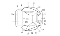
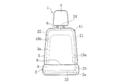
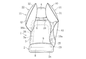
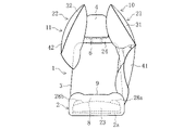
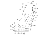
- FIG. 1A is a diagram showing the airbag in a completed inflation and deployment state (inflation completed state) in the airbag device according to the embodiment, and is a diagram of a seat on which an occupant is seated as seen from the front.
- FIG. 1B is a diagram showing an airbag in a fully inflated state, and is a diagram of a seat with no occupant as viewed from the front.
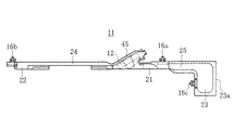
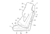
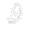
- FIG. 1C is a diagram showing an airbag in a fully inflated state, and is a diagram of a seat with no occupant as viewed from the side of the first side cushion.
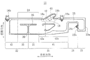
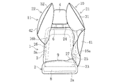
- FIG. 1D is a diagram showing the airbag in a fully inflated state, and is a diagram of the seat with no occupant as viewed from above.
- FIG. 1A is a diagram showing the airbag in a completed inflation and deployment state (inflation completed state) in the airbag device according to the embodiment, and is a diagram of a seat on which an occupant is seated as seen from the front.
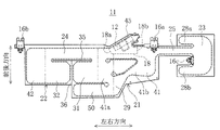
- FIG. 2 is a plan view of the airbag in a flat state in the airbag device according to the embodiment.
- FIG. 3 is a plan view of the airbag in the stowed configuration.
- FIG. 4 is a front view of the seat showing the stowed state of the airbag.
- FIG. 5 is a plan view of an airbag in a flat state in an airbag device according to a first modified example of the embodiment.
- FIG. 6A is a diagram showing an airbag in a fully inflated state in an airbag device according to a first modified example of the embodiment, and is a diagram of a seat with no occupant as viewed from the front.
- FIG. 6B is a diagram showing the airbag in a fully inflated state, and is a diagram of the seat with no occupant as viewed from above.
- FIG. 7 is a plan view of an airbag placed flat in an airbag device according to a second modification of the embodiment.
- FIG. 8A is a diagram showing an airbag in a fully inflated state in an airbag device according to a second modification of the embodiment, and is a diagram of a seat with no occupant as viewed from the front.
- FIG. 8B is a diagram showing the airbag in a fully inflated state, and is a diagram of the seat with no occupant seen from the side of the first side cushion.
- FIG. 9 is a plan view of an airbag placed flat in an airbag device according to a third modification of the embodiment.
- FIG. 10A is a diagram showing an airbag in a fully inflated state in an airbag device according to a third modification of the embodiment, and is a diagram of a seat with no occupant as viewed from the front.
- FIG. 10B is a diagram showing the airbag in a fully inflated state, and is a diagram of the seat with no occupant seen from the side of the first side cushion.
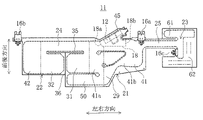
- FIG. 11 is a plan view of an airbag placed flat in an airbag device according to a fourth modification of the embodiment.
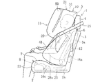
- FIG. 12A is a diagram showing an airbag in a fully inflated state in an airbag device according to a fourth modification of the embodiment, and is a diagram of a seat on which an occupant is seated as seen from the front.
- FIG. 12B is a diagram showing the airbag in a fully inflated state, and is a diagram of the seat on which the occupant is seated, viewed from the side of the first side cushion.
- FIG. 12C is a diagram showing the airbag in a fully inflated state, and is a diagram of the seat on which the occupant is seated, viewed from above.
- FIG. 13 is a plan view of an airbag placed flat in an airbag device according to a fifth modification of the embodiment.
- FIG. 14A is a diagram showing an airbag in a fully inflated state in an airbag device according to a fifth modification of the embodiment, and is a diagram of a seat on which an occupant is seated as seen from the front.
- FIG. 14B is a diagram showing the airbag in a fully inflated state, and is a diagram of the seat with no occupant seen from the side of the first side cushion.
- FIG. 15 is a plan view of an airbag placed flat in an airbag device according to a sixth modification of the embodiment.
- FIG. 16A is a diagram showing an airbag in a fully inflated state in an airbag device according to a sixth modification of the embodiment, and is a diagram of a seat on which an occupant is seated as seen from the front.
- FIG. 16B is a diagram showing the airbag in a fully inflated state, and is a diagram of the seat with no occupant seen from the side of the first side cushion.
- the terms “upper” and “upper” refer to the direction of the head of the occupant 5 seated in the normal position of the seat 1, and the terms “lower” and “lower” refer to the direction of the feet of the occupant 5.
- the “normal position” is the center position of the seat cushion 2 in the seat 1 in the left-right direction, and the position where the back of the occupant 5 is in contact with the backrest portion 3 from above and below.
- the terms “front” and “front side” may refer to the front direction of the occupant 5 seated in the normal position of the seat 1, and the terms “rear” and “rear side” may refer to the back direction of the occupant 5.
- left and right side may refer to the left side of the occupant 5 seated in the normal position of the seat 1, and the terms “right” and “right side” may refer to the right side of the occupant 5.
- the occupant 5 is assumed to be a WorldSID (World Side Impact Dummy) AM50 (50th percentile of American adult males).
- a pair of side cushions 21 and 22 provided on both sides of a vehicle seat 1 and a seat surface airbag cushion 23 incorporated in the seat cushion 2 are integrated into one airbag 11. It is a bag device 10 .
- the seat 1 on which the airbag device 10 is mounted will be described below.
- the seat 1 includes a seat cushion 2 and a backrest portion 3, as shown in FIGS. 1A to 1D.
- a headrest 4 is attached to the upper end portion of the backrest portion 3 via a rod-shaped support member 6 .
- the seat 1 may be one in which the backrest portion 3 and the headrest 4 are integrally formed.
- the side closer to the door for seat 1 may be called the "near side”
- the side farther from the door for seat 1 may be called the "far side”.
- a pad 8 is provided on the upper side of a seat pan (lower support member) 2a forming part of the seat frame, and the pad 8 is covered with a skin material 9.
- the skin material 9 is exposed on the seat surface (upper surface) of the seat cushion 2 .
- a pad 8 is provided on the front side of a seat back frame 3a forming part of the seat frame, and the pad 8 is covered with a skin material 9. As shown in FIG.
- the airbag device 10 includes an airbag 11 and an inflator 12 (see FIG. 1C).
- the airbag 11 is a fabric bag.
- the inflator 12 is a device that injects gas for inflating the airbag 11 .
- the airbag device 10 provided in the driver's seat or the front passenger's seat which is adjacent to each other on the left and right will be described as an example.
- the airbag 11 includes a first side cushion 21 that inflates and deploys to cover one side of the occupant 5, and an airbag 11 that inflates and deploys to cover the other side of the occupant 5.
- a first duct 24 communicating with the two side cushions 22 and a second duct 25 communicating the first side cushion 21 and the seat airbag cushion 23 are provided.
- the first duct 24 corresponds to a connection member that connects the first side cushion 21 and the second side cushion 22 .
- the second duct 25 is a member that connects the first side cushion 21 and the seat airbag cushion 23, and corresponds to a duct portion.
- the first side cushion 21 is provided on the near side of the seat 1.
- the rear side of the first side cushion 21 is fixed to the near side of the seat 1.
- the first side cushion 21 extends forward from its fixed position to the seat 1, as shown in FIGS. 1C and 1D.
- the first side cushion 21 includes a first head cushion portion 31 that inflates and deploys so as to cover one side of the head of the occupant 5, and one side of the torso (from the shoulder to the abdomen) of the occupant 5. and a first body cushion portion 41 that inflates and deploys to cover.
- the first head cushion portion 31 stands obliquely upward in a rearward direction from the front portion of the first body cushion portion 41 .
- the second side cushion 22 is provided on the far side of the seat 1.
- the rear side of the second side cushion 22 is fixed to the far side of the seat 1.
- the second side cushion 22 extends forward from its fixed point to the seat 1, as shown in FIG. 1D.
- the second side cushion 22 includes a second head cushion portion 32 that inflates and deploys so as to cover the other side portion of the head of the occupant 5, and a second side cushion portion 32 that covers the other side portion of the torso (shoulder portion) of the occupant 5. and a second body cushion portion 42 that inflates and deploys.
- the second head cushion portion 32 stands obliquely upward in a rearward direction from the front portion of the second body cushion portion 42 .
- the seat surface airbag cushion 23 inflates at the front portion within the seat cushion 2 to raise the front portion of the seat surface.
- the front portion of the seat cushion 2 refers to the front half of the seating area of the seat cushion 2 (the area of the upper surface of the seat cushion 2 other than the area covered by the backrest portion 3).
- the seat airbag cushion 23 is inflated, for example, between the seat pan 2a and the pad 8, as shown in FIG. 1C.
- the seat airbag cushion 23 extends from one side of the seat cushion 2 to the other side in the width direction of the seat 1, as shown in FIG. 1D.
- the installation range of the seat airbag cushion 23 may extend to the rear portion of the seat cushion 2 .
- the first duct 24 is a tubular duct through which gas can flow.
- the first duct 24 extends in the width direction of the seat 1 along the upper end surface of the backrest portion 3, as shown in FIG. 1B.
- One end of the first duct 24 opens into the first side cushion 21 and the other end of the first duct 24 opens into the second side cushion 22 .
- the first duct 24 is positioned below the top of the head of the occupant 5 in the height range above the seat 1 .
- the first duct 24 is positioned in front of the gap between the backrest portion 3 and the headrest 4 .
- the first duct 24 is thick enough to cover the range from the upper end of the backrest 3 to the lower end of the headrest 4 .
- the "height range of the upper portion of the seat 1" refers to the range above the center of the backrest portion 3 in the vertical direction.
- the second duct 25 is a tubular duct through which gas can flow.
- the second duct 25 has a gas passage area (cross-sectional area in an expanded state) smaller than that of the first duct 24 .
- the gas passage area of the second duct 25 may be larger than that of the first duct 24 or may be the same as that of the first duct 24 .
- the second duct 25 extends in the front-rear direction inside one side portion (near-side side portion) of the seat cushion 2 and is connected to the seat airbag cushion 23 at the front portion of the seat cushion 2 .
- the second duct 25 is positioned, for example, between the seat pan 2a and the pad 8, as indicated by the dashed line in FIG. 1C.
- the side portion of the seat cushion 2 is the vicinity of the side surface of the seat cushion 2, for example, a range of 10 cm from the side surface of the seat cushion 2. As shown in FIG.
- the airbag 11 is a bag formed by stacking two base fabrics of the same shape and size and sewing them at predetermined locations such as the outer periphery. In FIG. 2, the sewing location is represented by a thick dashed line. As shown in FIG. 2, the airbag 11 has main body portions 21 and 22 formed of a first side cushion 21 and a second side cushion 22 and having a laterally long substantially rectangular shape. In the description of the airbag 11 in the flat state, the longitudinal direction of the main body portions 21 and 22 of the airbag 11 is referred to as the "left-right direction" and the widthwise direction as the "front-rear direction". The side where 22 is fixed to the seat 1 (the upper side in FIG. 2) is called the “rear side", and the opposite side is called the "front side".
- the airbag 11 includes a first duct 24 extending in the left-right direction, a first side cushion 21 connected to one end of the first duct 24, a second side cushion 22 connected to the other end of the first duct 24, A second duct 25 connected to the outer end of the first side cushion 21 (the right end in FIG. 2) and a seat airbag cushion 23 connected to the outer end of the second duct 25 (the right end in FIG. 2).
- the first duct 24, the first side cushion 21, and the second side cushion 22 are rearward when the upper side in FIG. 2 is in an inflated state.
- the second duct 25 and the seat airbag cushion 23 are in a fully inflated state, and the right side (symbol 23a side) in FIG. Far side.
- the first duct 24 has a horizontally long, substantially rectangular shape.
- the first duct 24 is provided behind the airbag 11 .
- the front end of the first duct 24 (the position of the horizontal slit 35 in FIG. 2) is located behind the front ends of the first side cushion 21 and the second side cushion 22 .
- the dimension (thickness) of the first duct 24 in the front-rear direction is half or less of the dimension in the front-rear direction of each of the side cushions 21 and 22 .
- the first side cushion 21 has a first body cushion portion 41 positioned outside the first duct 24 in the left-right direction, and a first head cushion portion 31 positioned in front of the first duct 24 .
- the first body cushion portion 41 extends forward beyond the front end of the first duct 24 .
- the first head cushion portion 31 extends inward in the left-right direction (to the left in FIG. 2) from a portion of the first body cushion portion 41 that extends forward.
- the first head cushion part 31 has a substantially rectangular shape.
- the first head cushion portion 31 is adjacent to the first duct 24 via a horizontal slit 35 extending in the left-right direction.
- the first body cushion portion 41 has a laterally long substantially rectangular shape. Strictly speaking, the first body cushion portion 41 is an outer portion in the left-right direction, and the dimension in the front-rear direction gradually decreases toward the outer end.
- a portion of the first body cushion portion 41 on the side of the first duct 24 constitutes an upper cushion portion 41 a for protecting the side portion of the shoulder of the occupant 5 .
- a portion of the first body cushion portion 41 on the second duct 25 side constitutes a lower cushion portion 41 b for protecting the side portions of the chest and abdomen of the occupant 5 .
- "rectangle" includes a square.
- a housing portion 45 for the inflator 12 is formed on the rear side of the first body cushion portion 41 .
- a gas guide 18 is provided in the storage portion 45 .
- the gas guide 18 has a first outlet 18a that opens to the upper cushion portion 41a and a second outlet 18b that opens to the lower cushion portion 41b as outlets for the gas injected from the inflator 12 .
- the first body cushion portion 41 which takes less time to protect the occupant 5 from the collision, can be inflated and deployed ahead of the other cushion portions.
- the second side cushion 22 has a second body cushion portion 42 positioned outside the first duct 24 in the left-right direction, and a second head cushion portion 32 positioned in front of the first duct 24 .
- the second body cushion portion 42 extends forward beyond the front end of the first duct 24 .
- the second head cushion portion 32 extends inward in the left-right direction (to the right in FIG. 2) from a portion of the second body cushion portion 42 that extends forward.
- the second head cushion part 32 has a substantially rectangular shape.
- the second head cushion portion 32 is adjacent to the first duct 24 via the lateral slit 35 described above.
- the second body cushion portion 42 has a substantially rectangular shape that is slightly vertically long.
- the second body cushion part 42 is a part for protecting the side part of the shoulder of the occupant 5 .
- the tips of the first head cushion part 31 and the second head cushion part 32 are adjacent to each other via a longitudinal slit 36 extending in the front-rear direction.
- the first head cushion part 31 and the second head cushion part 32 are formed symmetrically with the vertical slit 36 interposed therebetween.
- the vertical slit 36 is a slit extending in the front-rear direction from the front end of the airbag 11 and connected to the center position of the horizontal slit 35 on the rear side.
- the horizontal slits 35 extend leftward and rightward from the positions of the rear ends of the vertical slits 36 .
- Combining the horizontal slit 35 and the vertical slit 36 forms a substantially T-shaped notch.
- each of the slits 35 and 36 is a cut with almost no gap, but it may be a cut with a certain amount of gap.
- the second duct 25 has a horizontally long, substantially rectangular shape.
- the second duct 25 is provided behind the airbag 11 .
- the second duct 25 extends from the rear portion of the first side cushion 21 and connects to the rear portion of the seat airbag cushion 23 .
- the front end of the second duct 25 is located behind the front ends of the first side cushion 21 and the seat airbag cushion 23 .
- the second duct 25 is shorter in size (thickness) in the front-rear direction than the first duct 24 .
- the longitudinal dimension of the second duct 25 may be longer than that of the first duct 24 or may be the same as that of the first duct 24 .
- the seat airbag cushion 23 has a substantially rectangular shape.
- the seat airbag cushion 23 extends forward beyond the front end of the second duct 25 .
- the seat airbag cushion 23 has a dimension in the front-rear direction (the width direction of the seat 1 in the stowed state described later) larger than its dimension in the left-right direction (the front-rear direction of the seat 1 in the stowed state).
- the longitudinal dimension of the seat airbag cushion 23 can be adjusted according to the width of the seat cushion 2 .
- the airbag 11 is provided with a plurality of tabs 16a to 16c as fixing portions for fixing the airbag 11 to the seat frames 2a and 3a of the seat 1 (see FIG. 2).
- the airbag 11 includes a first tab 16a provided in the vicinity of the second duct 25 on the outer peripheral portion on the rear side of the first side cushion 21, and a tab 16a on the outer peripheral portion on the rear side of the second side cushion 22.
- a second tab 16b provided at the outer end (the left end in FIG. 2) and a third tab 16c provided at the inner peripheral portion 23b of the seat airbag cushion 23 are provided.
- FIG. 1 a storage form when the airbag 11 is stored in the seat 1 and a storage state in which the airbag 11 is stored in the seat 1 will be described with reference to FIGS. 3 and 4.
- FIG. 3 a storage form when the airbag 11 is stored in the seat 1 and a storage state in which the airbag 11 is stored in the seat 1 will be described with reference to FIGS. 3 and 4.
- the airbag 11 is stored in the seat 1 by folding the first duct 24, the first side cushion 21, and the second side cushion 22 so that the dimension in the front-rear direction is shortened in the flat state. It becomes a storage form (see FIG. 3).
- the head cushion portions 31 and 32 are folded outward at their roots and overlapped with the body cushion portions 41 and 42, and then rolled from the front side to the rear side.
- a winding method can be adopted.
- other methods such as folding in a bellows shape may be adopted.
- the attachment positions of the tabs 16a and 16b or the bent portions (described later) of the second duct 25 may be wrapped with a cloth material that breaks when the airbag 11 is inflated and deployed.
- the stored airbag 11 is stored in the seat 1 with the first duct 24, the first side cushion 21, and the second side cushion 22 folded along the seatback frame 3a.
- the first duct 24 is stored at the upper end of the backrest portion 3
- the first side cushion 21 is stored at the near side of the seat 1
- the second side cushion 22 is stored at the far side of the seat 1.
- the second duct 25 is housed between the seat pan 2a and the pad 8 on the near-side side of the seat cushion 2 in an unfolded state.
- the second duct 25 extends forward from near the lower end of the seatback frame 3a on the near side.
- the seat airbag cushion 23 is accommodated between the seat pan 2a and the pad 8 in the front portion of the seat cushion 2 in an unfolded state.
- the seat airbag cushion 23 extends from the near side to which the second duct 25 is connected toward the far side.
- the seat airbag cushion 23 has a side 23 a positioned at the outer end in a flat state and extends in the width direction of the seat 1 along the front end of the seat cushion 2 .
- the stowed airbag 11 stowed in the seat 1 is fixed to the seat frames 2a and 3a of the seat 1 at four points, ie, the three tabs 16a to 16c and the stowage portion 45 of the inflator 12.
- the body cushion portions 41 and 42 are fixed to the seatback frame 3a by the first tab 16a and the second tab 16b, respectively.
- the seat airbag cushion 23 is fixed to the seat pan 2a by the third tab 16c at the center of the inner side 23b in the flat state.
- an insertion hole for a stud bolt (not shown) projecting from the inflator 12 is formed in the storage portion 45 .
- the storage portion 45 having the stud bolt passed through the insertion hole is also fixed to the seatback frame 3a.
- the arrangement and number of tabs 16a to 16c are not limited to those of this embodiment.
- the inflator 12 receives a signal from the sensor and injects gas into the first side cushion 21 .
- the first side cushion 21 is inflated and deployed.
- part of the gas injected to the first side cushion 21 is supplied to the second side cushion 22 through the first duct 24 .
- the second side cushion 22 is inflated and deployed.
- part of the gas injected to the first side cushion 21 is supplied to the seat airbag cushion 23 through the second duct 25 .
- the seat airbag cushion 23 is inflated at its installation location.
- the occupant 5 moves to the side where the collision occurred due to the inertial force at the beginning of the collision, and then moves to the opposite side due to the impact force of the collision. Specifically, in the case of a far-side side collision, the occupant 5 collides with the second side cushion 22 at the beginning of the collision. Along with this collision, the first side cushion 21 connected through the first duct 24 moves to the far side together with the second side cushion 22 . After that, when the occupant 5 moves to the side opposite to the initial stage of the collision, the occupant 5 collides with the first side cushion 21 .
- the occupant 5 collides with the first side cushion 21 at the beginning of the collision, and the first side cushion 21 and the second side cushion 22 move to the near-side. After that, when the occupant 5 moves to the side opposite to the initial stage of the collision, the occupant 5 collides with the second side cushion 22 .
- the first duct 24 is positioned in the height range where the occupant 5 collides with the side cushions 21 and 22 at the initial stage of collision. Therefore, a lateral load acts on the first duct 24, and both side cushions 21 and 22 move laterally together. As a result, the travel distance of the occupant 5 moving in the opposite direction from the initial stage of the collision until it collides with the other side cushions 21 and 22 is shortened, and the occupant 5 is restrained early. In addition, since the side cushions 21 and 22 with which the occupant 5 collides at the initial stage of the collision are restrained to some extent by the first duct 24, the amount of outward movement of the seat 1 is suppressed, and the collision occurrence side is also restrained early. In this manner, the side cushions 21 and 22 exhibit occupant restraint performance in response to a side collision of the vehicle.
- the airbag device 10 can quickly restrain the occupant 5 because the side cushions 21 and 22 on both sides behave together.
- the seat surface airbag cushion 23 inflates, causing the seat cushion 2 to move forward.
- the front portion of the surface is raised across the width.
- the raised portion of the seat surface lifts and restrains the thighs of the occupant 5, restricting forward movement of the lumbar region of the occupant 5.
- the seat airbag cushion 23 exerts the occupant restraint performance in response to a frontal collision.
- the pair of side cushions 21 and 22 and the seat airbag cushion 23 can be inflated with one inflator 12.
- the installation space for the inflator 12 is reduced compared to the case where an inflator is installed on each cushion.
- the entire airbag 11 can be inflated by one inflator 12, an increase in the number of parts of the airbag device 10 can be suppressed.
- an inflator is arranged below the airbag built into the seat cushion.
- a mounting space for the inflator is required in the frame on the seat pan side.
- there is no need for an installation space for the inflator 12 in the seat cushion 2 and it is possible to widen the range of packaging and design of various equipment in the seat 1.
- the airbag 11 having the side cushions 21 and 22 that inflate and deploy close to the occupant 5 is integrated with the seat airbag cushion 23 that inflates close to the occupant 5.
- the structure for the airbag provided in the seat 1 can be efficiently simplified. Further, since each of the cushions 21 to 23 inflates at a position close to the occupant 5, high restraint performance can be exhibited.
- the second duct 25 is built into one side of the seat cushion 2 .
- the place where the second duct 25 is built is, for example, a passenger car equipped with an automatic driving function, and even if the passenger 5 takes a free posture, the weight of the passenger 5 is less likely to act thereon. Therefore, the flow of gas in the second duct 25 is less likely to be hindered by the weight of the occupant 5 , and the seat airbag cushion 23 can be smoothly inflated regardless of the posture of the occupant 5 .
- the second duct 25 is attached to the first side cushion 21 to which the inflator 12 is attached. Therefore, the gas injected from the inflator 12 can be quickly supplied to the seat airbag cushion 23, and the seat airbag cushion 23 can be quickly inflated.
- the gas in the seat airbag cushion 23 can be released to the first side cushion 21 through the second duct 25. can. That is, the second duct 25 functions as a vent hole. Therefore, installation of a vent hole in the seat airbag cushion 23 can be omitted.
- the third tab 16c is attached to the rear portion of the seat airbag cushion 23 to fix the rear portion to the seat pan 2a. Therefore, even if the thigh of the occupant 5 hits the raised portion of the seat airbag cushion 23 from behind in the event of a frontal collision or the like, the forward displacement of the seat airbag cushion 23 is suppressed. can do.
- the airbag device 10 can be installed on either the front seat or the rear seat of the vehicle, and can also be installed on the seat of a single-seat vehicle. Further, since the airbag device 10 does not depend on the layout of the vehicle, it is possible to modularize part or all of the airbag device 10 so that it can be applied to a plurality of vehicle types.
- the airbag device 10 further includes a second connection member 26 that connects the second side cushion 22 and the seat airbag cushion 23 .
- the second connection member 26 is a string-like or thin band-like member (for example, a tether).
- one end of the second connection member 26 is fixed at a position near the rear of the outer end 42 a of the second body cushion portion 42 .
- a non-inflatable portion 23d for fixing the other end of the second connecting member 26 is provided continuously from the seat airbag cushion 23. As shown in FIG.
- the non-inflatable portion 23d is provided on the side opposite to the side to which the second duct 25 is connected.
- the second connecting member 26 passes through the inside of the skin material 9 of the backrest portion 3 and the inside of the skin material 9 of the seat cushion 2 when the airbag 11 is stored in the seat 1 .
- the second connecting member 26 can pass between the seat back frame 3a and the pad 8 in the backrest portion 3, and can pass between the seat pan 2a and the pad 8 in the seat cushion 2.
- the other end of the second connecting member 26 is fixed to the non-inflatable portion 23d arranged on the far side by sewing or the like (see FIGS. 6A and 6B).
- the second connection member 26 extends downward from the end of the second body cushion portion 42 along the far side of the seat back frame 3 a in the backrest portion 3 and reaches the seat cushion 2 . .
- the second connecting member 26 bends forward within the seat cushion 2 and extends forward on the far side to reach the non-inflatable portion 23d.
- the reaction force of the first side cushion 21 acts through the second duct 25 and the reaction force of the second side cushion 22 acts through the second connection member 26 .
- the first side cushion 21 is fixed to the seat back frame 3a by the first tab 16a near the second duct 25, and the second side cushion 22 is fixed to the seat back frame 3a by the second tab 16b near the second connecting member 26. It is fixed to the back frame 3a, and each reaction force described above becomes relatively strong. Therefore, it is possible to suppress forward displacement of the seat airbag cushion 23 . Further, the fixing portion (third tab 16c) for fixing the seat airbag cushion 23 to the seat pan 2a can be omitted.
- the structure of the seat pan 2a needs to be changed accordingly, and it is preferable to dispose the seat airbag cushion 23 right above the seat pan 2a. Fixing by 16c is easy.
- the third tab 16c is omitted, the seat pan 2a does not need to be structurally changed, and the seat airbag cushion 23 can be easily arranged between the pad 8 and the upholstery 9.
- FIG. the shape of the seat surface can easily follow the shape of the seat airbag cushion 23 when inflated, and the performance of restraining the occupant 5 in response to a frontal collision can be improved.
- the airbag device 10 further includes a seat side cushion 27 that inflates so as to raise the side of the seat of the seat cushion 2 (the side on the near side).
- the seat side cushion 27 is formed continuously with the second duct 25, as shown in FIG.
- the seat side cushion 27 is more flexible than the inlet 25a on the side of the first side cushion 21 and the outlet 25b on the side of the seat airbag cushion 23.
- the duct diameter of the portion where is formed (the dimension in the front-rear direction when placed flat) is large.
- the airbag device 10 includes a first seat side cushion 28a that inflates so as to raise one side of the seat surface of the seat cushion 2, and the other side of the seat cushion 2. and a second seat side cushion 28b that expands to raise the seat.
- the seat side cushions 28 a and 28 b are formed continuously with the seat airbag cushion 23 .
- the first seat side cushion 28a extends toward the first side cushion 21 from the rear portion (the upper portion in FIG. 9) of the inner portion of the outer circumference of the seat airbag cushion 23.
- the second seat side cushion 28b extends toward the first side cushion 21 from the front portion of the inner portion (lower portion in FIG. 9).
- the second duct 25 extends so as to be adjacent to the front side of the first seat side cushion 28a, and is connected to the seat airbag cushion 23 immediately in front of the first seat side cushion 28a.
- the gas when gas is injected from the inflator 12, the gas is supplied to the seat side cushions 28a and 28b through the seat airbag cushion 23, and as shown in FIGS.
- the seat side cushions 28a, 28b are inflated to raise each side of the seat cushion 2's seat surface.
- the seat side cushions 28a and 28b extend rearward from the rear portion of the seat airbag cushion 23.
- both the occupant 5 trying to move to the near side and the occupant 5 trying to move to the far side at the time of a side collision hit the portion raised by the seat side cushion 28a or the seat side cushion 28b.
- the seat side cushions 27 of the second modified example may be provided instead of the first seat side cushions 28a.
- the airbag device 10 further includes a front head protection cushion 50 that inflates and deploys in front of the head of the occupant 5 .
- the front head protection cushion 50 communicates with the first side cushion 21 via the third duct 29 .
- the third duct 29 corresponds to a third connecting member.
- the front head protection cushion 50 is arranged so as to be adjacent to the front side of the first head cushion portion 31 .
- the inlet of the front head protection cushion 50 is connected to the front portion of the first side cushion 21 via the third duct 29 .
- the gas when gas is injected from the inflator 12, the gas is supplied to the front head protection cushion 50 via the first side cushion 21 and the third duct 29, as shown in FIGS. 12A to 12C. , the head front protection cushion 50 is inflated and deployed. In the inflated state, the third duct 29 extends inward from the inner surface of the first side cushion 21, and the front head protection cushion 50 extends upward from the connection point of the third duct 29. As shown in FIG.
- the thick dashed lines in FIGS. 12A and 12B represent sewing locations.
- the first side cushion 21 and the third duct 29 are interposed between the seat belt 15 and the occupant 5 in the fully inflated state. .
- the third duct 29 is received by the seat belt 15 . Therefore, a reaction force can be obtained to some extent when the head of the occupant 5 collides with the front head protection cushion 50 at the time of a frontal collision, etc., and the restraint performance of the occupant 5 in response to the frontal collision can be improved.
- the airbag device 10 further includes a first thigh outer cushion 61 that raises the outer portion of the seating surface of the seat cushion 2 below the thigh of the occupant 5 on the near side.
- the first outer thigh cushion 61 is provided only on the outer portion in the left-right direction of the lower side of the thigh on the near side of the occupant 5, and does not exist on the lower side of the thigh on the far side.
- the first outer thigh cushion 61 is slightly inflated into a vertically long shape and extends from the thigh of the occupant 5 to the waist.
- the seat surface airbag cushion 23 does not inflate to the entire lateral direction of the seat surface of the seat cushion 2, and the first thigh outer cushion 61 is positioned at the outer portion below the thigh on the near side of the occupant 5. Inflate.
- the first thigh outer cushion 61 extends toward the first side cushion 21 at the rear portion of the seat airbag cushion 23 (upper portion in FIG. 13).
- the second duct 25 is connected to the first outer thigh cushion 61 .
- a non-inflatable portion 62 is formed in the front portion (lower portion in FIG. 13) of the seat airbag cushion 23 where the first thigh outer cushion 61 does not exist.
- the gas when gas is injected from the inflator 12, the gas is supplied to the first thigh outer cushion 61, and as shown in FIGS. 14A and 14B, the first thigh outer cushion 61 is inflated. to raise the outer portion under the thigh of the occupant 5 on the near side.
- the first outer thigh cushion 61 In the fully inflated state, the first outer thigh cushion 61 extends from the outer portion under the thigh of the occupant 5 to the waist.
- the first side cushion 21 expands, and at the same time, the outer portion below the thigh on the near side of the occupant 5 expands.
- the body of 5 can be tilted away from the side door.
- the first outer thigh cushion 61 does not need to tilt the body of the occupant 5 completely.
- the inflated first thigh outer cushion 61 moderately tilts the body of the occupant 5 to prevent the occupant 5 from moving in the collision direction due to inertia and colliding with the side door. .
- the airbag device 10 includes, in addition to the above-described first thigh outer cushion 61, a second outer thigh cushion 61 that raises an outer portion of the seating surface of the seat cushion 2 below the thigh on the far side side of the occupant 5.
- An outer thigh cushion 63 is further provided.
- the second thigh outer cushion 63 is provided on the outer portion in the left-right direction of the lower thigh of the occupant 5 on the far side.
- the second outer thigh cushion 63 is slightly inflated into a vertically long shape and extends from the thigh of the occupant 5 to the waist.
- the first thigh outer cushion 61 extends toward the first side cushion 21 at the rear portion of the seat airbag cushion 23 (upper portion in FIG. 15).
- the second thigh outer cushion 63 extends toward the first side cushion 21 side.
- the fourth duct 64 is connected to the second duct 25 and branches the first thigh outer cushion 61 and the second thigh outer cushion 63 .
- the fourth duct 64 corresponds to a fourth connecting member.
- a non-inflatable portion 62 is formed at the right end portion of the seat airbag cushion 23 .
- An active valve 65 is provided in the fourth duct 64 .
- the active valve 65 is connected to a control device (not shown) and can control opening and closing of the fourth duct 64 according to the direction in which the collision has occurred. Specifically, when a collision occurs from the near side, the active valve 65 opens the first thigh outer cushion 61 side and closes the second thigh outer cushion 63 side. Conversely, when a collision occurs from the far side, the second thigh outer cushion 63 side is opened, while the first thigh outer cushion 61 side is closed.
- the active valve 65 and the controller that controls the opening/closing of the fourth duct 64 by operating the active valve 65 correspond to opening/closing control means.
- FIGS. 16A and 16B show a state in which the second thigh outer cushion 63 is inflated and the outer portion below the thigh on the far side side of the occupant 5 is raised. In the fully inflated state, the second thigh outer cushion 63 extends from the outer portion below the thigh of the occupant 5 to the waist.
- the second side cushion 22 expands, and at the same time, the outer portion below the far side thigh of the occupant 5 expands, pushing the waist of the occupant 5.
- the body of the occupant 5 can be moderately inclined in the direction away from the passenger seat side.
- a first outer thigh cushion 61 and a second outer thigh cushion 63 are provided on the seat airbag cushion 23 and are separated into left and right.
- the direction in which the body of the occupant 5 is tilted at the time of collision can be switched.
- the second side cushion 22 may be omitted.
- the airbag 11 may be an assembly of the near-side side cushion 21 and the seat airbag cushion 23 .
- the airbag 11 may be a combination of the side cushion 22 on the far side and the airbag cushion 23 for the seat surface.
- the second duct 25 is provided on the far side and allows the side cushion 22 on the far side and the seat airbag cushion 23 to communicate with each other.
- the connecting member 24 that connects the first side cushion 21 and the second side cushion 22 is a duct, but the connecting member 24 may be a member through which gas cannot flow.
- a second inflator may be attached to the second side cushion 22, or a bifurcated pipeline may be used so that gas is supplied from one inflator to both side cushions 21 and 22.
- the airbag device 10 may be constructed.
- the inflator 12 is attached to the first side cushion 21 in the above embodiment, the inflator 12 may be attached to the second side cushion 22 . Further, for example, when the volume of the airbag 11 is large as in the fourth modification, one inflator 12 may be attached to each of the first side cushion 21 and the second side cushion 22 .
- the seat airbag cushion 23 is stored in the seat cushion 2 in an unfolded state without being folded, but the seat airbag cushion 23 may be stored in a folded state.
- only one of the first side cushion 21 and the second side cushion 22 may be provided with the head cushion portions 31 and 32 .
- the present invention can be applied to an airbag device or the like that protects the sides of an occupant.
Landscapes
- Engineering & Computer Science (AREA)
- Mechanical Engineering (AREA)
- Aviation & Aerospace Engineering (AREA)
- Transportation (AREA)
- Air Bags (AREA)
Abstract
Provided is an airbag device having a vehicle occupant-restraining capability for handling a side collision of a vehicle, and a vehicle occupant restraining capability for handling a front collision, wherein the space required for mounting the airbag device is reduced. An airbag device 10 comprises: an airbag 11 having a side cushion 21 which expands and deploys so as to cover one lateral area of an occupant 5 seated on a seat 1 of a vehicle; and an inflator 12 which injects gas for expanding the side cushion 21. The airbag 11 further includes: a seat surface airbag cushion 23 which expands and raises a seat surface of a seat cushion 2 such that forward movement of the waist of the occupant 5 is restricted; and a duct part 25 for linking the side cushion 21 and to the seat surface airbag cushion 23.
Description
本発明は、乗員の側部等を保護するエアバッグ装置等に関する。
The present invention relates to an airbag device or the like that protects the sides of an occupant.
従来から、車両の側面衝突に対応した乗員の拘束性能を有するエアバッグ装置が知られている。この種のエアバッグ装置では、座席に着座した乗員の側部を覆うように、エアバッグが膨張展開する。特許文献1には、乗員に対してニアサイドからの衝撃に対してもファーサイドからの衝撃に対しても保護することができる乗員拘束装置が記載されている。
Conventionally, there has been known an airbag device that has occupant restraint performance in response to a side collision of a vehicle. In this type of airbag device, the airbag inflates and deploys so as to cover the sides of the passenger seated on the seat. Patent Literature 1 describes an occupant restraint device capable of protecting an occupant from both near-side impact and far-side impact.
また、特許文献2には、別のタイプのエアバッグ装置として、シートクッションエアバッグ装置が記載されている。この装置は、車両用シート等の乗物用シートの座部内に配置されたエアバッグを膨張用ガスにより膨張させて座面を隆起させ、座部上の乗員等の被拘束対象体が前方へ移動するのを規制するようにしたものである。
In addition, Patent Document 2 describes a seat cushion airbag device as another type of airbag device. This device inflates an airbag arranged in a seat portion of a vehicle seat such as a vehicle seat by means of an inflation gas to raise the seat surface so that an object to be restrained such as an occupant on the seat moves forward. It is designed to regulate the
ところで、従来は、1つの座席に対し複数のエアバッグ装置を設ける場合、エアバッグ装置ごとにインフレータが設けられる。この場合、エアバッグ装置の数に応じてインフレータの設置スペースが必要となる。それに対し、本願発明者は、自動運転の機能を搭載する乗用車では、乗員の姿勢の自由度が向上するため、乗員にとって自由度の高い車室空間の設計が求められるようになり、そのためにはエアバッグ装置の搭載スペースを縮小することが望ましいと考えた。
By the way, conventionally, when a plurality of airbag devices are provided for one seat, an inflator is provided for each airbag device. In this case, installation space for the inflators is required according to the number of airbag devices. On the other hand, the inventor of the present application believes that in a passenger car equipped with an automatic driving function, the degree of freedom of the occupant's posture is improved. We thought it would be desirable to reduce the mounting space for the airbag system.
本発明は、このような事情に鑑みてなされたものであり、車両の側面衝突に対応した乗員の拘束性能と、前面衝突に対応した乗員の拘束性能とを有するエアバッグ装置において、その搭載スペースを縮小させることを目的とする。
SUMMARY OF THE INVENTION The present invention has been made in view of such circumstances. The purpose is to reduce
本発明に係るエアバッグ装置は、車両の座席に着座した乗員の一方の側部を覆うように膨張展開するサイドクッションを有するエアバッグと、サイドクッションを膨張させるガスを噴射するインフレータとを備え、エアバッグは、乗員の腰部の前方への移動が規制されるように、膨張してシートクッションの座面を隆起させる座面用エアバッグクッションと、サイドクッションと座面用エアバッグクッションとを連通させるダクト部とをさらに有する。
An airbag device according to the present invention includes an airbag having a side cushion that inflates and deploys so as to cover one side of an occupant seated in a vehicle seat, and an inflator that injects gas to inflate the side cushion, The airbag communicates between the seat airbag cushion, which inflates to raise the seat surface of the seat cushion, the side cushions, and the seat airbag cushion, so as to restrict forward movement of the occupant's waist. and a duct portion for allowing the air to flow.
本発明は、サイドクッションを第1サイドクッションとして、エアバッグは、乗員の他方の側部を覆うように膨張展開する第2サイドクッションと、座席の幅方向に延びて第1サイドクッションと第2サイドクッションとを接続する接続部材とをさらに有していてもよい。
According to the present invention, the side cushion is a first side cushion, and the airbag is composed of a second side cushion that inflates and deploys so as to cover the other side of the occupant, and a first side cushion and a second side cushion that extend in the width direction of the seat. It may further have a connecting member that connects with the side cushion.
本発明は、接続部材は、内部をガスが流通可能なダクトであり、第2サイドクッションは、接続部材の内部を介して、第1サイドクッションに連通させてもよい。
In the present invention, the connection member may be a duct through which gas can flow, and the second side cushion may communicate with the first side cushion via the interior of the connection member.
本発明は、接続部材を第1接続部材として、シートクッションに内蔵されて、第2サイドクッションと座面用エアバッグクッションとを接続する第2接続部材をさらに備えていてもよい。
The present invention may further include a second connection member, which is incorporated in the seat cushion and connects the second side cushion and the seat airbag cushion, using the connection member as the first connection member.
本発明は、インフレータは、第1サイドクッションに取り付けられ、インフレータから噴射されるガスの一部は、第1サイドクッションからダクト部を介して座面用エアバッグクッションに供給されるようにしてもよい。
According to the present invention, the inflator is attached to the first side cushion, and part of the gas injected from the inflator is supplied from the first side cushion to the seat airbag cushion through the duct. good.
本発明は、第1サイドクッションは、座席用のドアに近いニアサイドに設けられていてもよい。
In the present invention, the first side cushion may be provided on the near side near the door for the seat.
本発明は、座面用エアバッグクッションは、シートクッション内の前部で膨張するように配置され、ダクト部は、シートクッションにおける一方の側部内を前後方向に延びて、シートクッションの前部で座面用エアバッグクッションに繋がっていてもよい。
According to the present invention, the seat airbag cushion is arranged to inflate in the front portion of the seat cushion, and the duct portion extends longitudinally in one side portion of the seat cushion and extends in the front portion of the seat cushion. It may be connected to the seat airbag cushion.
本発明は、エアバッグは、シートクッションの座面の側部を隆起させるように膨張する座面側部クッションをさらに備えていてもよい。
According to the present invention, the airbag may further include a seat side cushion that inflates so as to raise the side of the seat cushion.
本発明は、座面側部クッションは、ダクト部に連続して形成され、ダクト部を流通するガスが流入するようにしてもよい。
According to the present invention, the seat side cushion may be formed continuously with the duct portion so that the gas flowing through the duct portion may flow in.
本発明は、座面側部クッションは、座面用エアバッグクッションに連続して形成され、膨張完了状態では座面用エアバッグクッションの後部から後方に延びていてもよい。
In the present invention, the seat side cushion may be formed continuously with the seat airbag cushion, and may extend rearward from the rear portion of the seat airbag cushion in the fully inflated state.
本発明は、座席にエアバッグを固定する1つ又は複数の固定部をさらに備え、固定部の1つは、座面用エアバッグクッションの後部に取り付けられて、後部をシートクッションのシートフレームに固定するようにしてもよい。
The present invention further comprises one or more fixings for fixing the airbag to the seat, one of the fixings being attached to the rear of the seat airbag cushion and the rear to the seat frame of the seat cushion. It may be fixed.
本発明は、エアバッグは、サイドクッションに一体化されて乗員の頭部の前方で膨張展開する頭部前面保護クッションをさらに有していてもよい。
According to the present invention, the airbag may further have a front head protection cushion that is integrated with the side cushion and inflates and deploys in front of the occupant's head.
本発明では、ダクト部を介してサイドクッションと座面用エアバッグクッションとが連通しているため、インフレータから噴射されたガスは、サイドクッション及び座面用エアバッグクッションの両方に供給される。これにより、サイドクッションは、車両の側面衝突に対応した乗員の拘束性能を発揮し、座面用エアバッグクッションは、前面衝突に対応した乗員の拘束性能を発揮する。ここで、従来は、サイドクッションと座面用エアバッグクッションとが、別々のエアバッグ装置に設けられ、サイドクッションと座面用エアバッグクッションは連通していない。そのため、サイドクッションと座面用エアバッグクッションのそれぞれにインフレータが必要となる。それに対し、本発明では、1つのインフレータで、サイドクッションと座面用エアバッグクッションを膨張させることができ、インフレータの設置スペースを削減することが可能である。本発明によれば、車両の側面衝突に対応した乗員の拘束性能と、前面衝突に対応した乗員の拘束性能とを有するエアバッグ装置の搭載スペースを縮小させることができる。
In the present invention, since the side cushion and the seat airbag cushion are communicated through the duct portion, the gas injected from the inflator is supplied to both the side cushion and the seat airbag cushion. As a result, the side cushion exhibits occupant restraint performance against a side collision of the vehicle, and the seat airbag cushion exhibits occupant restraint performance against a frontal collision. Here, conventionally, the side cushions and the airbag cushion for the seat surface are provided in separate airbag devices, and the side cushions and the airbag cushion for the seat surface are not communicated with each other. Therefore, an inflator is required for each of the side cushion and the seat airbag cushion. In contrast, according to the present invention, a single inflator can inflate the side cushions and the seat airbag cushion, and the installation space for the inflator can be reduced. According to the present invention, it is possible to reduce the mounting space of an airbag device that has occupant restraint performance against a side collision of a vehicle and occupant restraint performance against a frontal collision.
以下、図面を参照しながら、本発明の実施形態を詳細に説明する。なお、以下の実施形態は、本発明の一例であって、本発明、その適用物、あるいはその用途の範囲を制限することを意図するものではない。
Hereinafter, embodiments of the present invention will be described in detail with reference to the drawings. The following embodiments are examples of the present invention, and are not intended to limit the scope of the present invention, its applications, or its uses.
また、本明細書において、「上」、「上側」とは座席1の正規の位置に着座した乗員5の頭部方向を、「下」、「下側」とは乗員5の足元方向を意味する場合がある。ここで、「正規の位置」とは、座席1におけるシートクッション2の左右方向の中心位置で、背もたれ部3に乗員5の背中が上下に亘って接する位置をいう。また、「前」、「前側」とは座席1の正規の位置に着座した乗員5の正面方向を、「後」、「後ろ側」とは乗員5の背面方向を意味する場合がある。また、「左」、「左側」とは座席1の正規の位置に着座した乗員5の左手方向を、「右」、「右側」とは乗員5の右手方向を意味する場合がある。また、乗員5は、WorldSID(国際統一側面衝突ダミー:World Side Impact Dummy)のAM50(米国人成人男性の50パーセンタイル)を想定したものである。
Further, in this specification, the terms “upper” and “upper” refer to the direction of the head of the occupant 5 seated in the normal position of the seat 1, and the terms “lower” and “lower” refer to the direction of the feet of the occupant 5. sometimes. Here, the “normal position” is the center position of the seat cushion 2 in the seat 1 in the left-right direction, and the position where the back of the occupant 5 is in contact with the backrest portion 3 from above and below. Further, the terms "front" and "front side" may refer to the front direction of the occupant 5 seated in the normal position of the seat 1, and the terms "rear" and "rear side" may refer to the back direction of the occupant 5. Further, the terms "left" and "left side" may refer to the left side of the occupant 5 seated in the normal position of the seat 1, and the terms "right" and "right side" may refer to the right side of the occupant 5. The occupant 5 is assumed to be a WorldSID (World Side Impact Dummy) AM50 (50th percentile of American adult males).
本実施形態は、車両の座席1の両サイドに設けられる一対のサイドクッション21,22と、シートクッション2に内蔵される座面用エアバッグクッション23とが1つのエアバッグ11に集約されたエアバッグ装置10である。以下では、エアバッグ装置10について説明を行う前に、エアバッグ装置10が搭載される座席1について説明を行う。
In this embodiment, a pair of side cushions 21 and 22 provided on both sides of a vehicle seat 1 and a seat surface airbag cushion 23 incorporated in the seat cushion 2 are integrated into one airbag 11. It is a bag device 10 . Before describing the airbag device 10, the seat 1 on which the airbag device 10 is mounted will be described below.
[座席の概略構成について]
座席1は、図1A~図1Dに示すように、シートクッション2と、背もたれ部3とを備えている。背もたれ部3の上端部には、棒状の支持部材6を介して、ヘッドレスト4が取り付けられている。なお、座席1は、背もたれ部3とヘッドレスト4とが一体形成されたものであってもよい。また、以下では、座席1用のドアに近い側を「ニアサイド」、座席1用のドアから遠い側を「ファーサイド」と言う場合がある。 [About the general configuration of the seats]
Theseat 1 includes a seat cushion 2 and a backrest portion 3, as shown in FIGS. 1A to 1D. A headrest 4 is attached to the upper end portion of the backrest portion 3 via a rod-shaped support member 6 . Note that the seat 1 may be one in which the backrest portion 3 and the headrest 4 are integrally formed. Also, hereinafter, the side closer to the door for seat 1 may be called the "near side", and the side farther from the door for seat 1 may be called the "far side".
座席1は、図1A~図1Dに示すように、シートクッション2と、背もたれ部3とを備えている。背もたれ部3の上端部には、棒状の支持部材6を介して、ヘッドレスト4が取り付けられている。なお、座席1は、背もたれ部3とヘッドレスト4とが一体形成されたものであってもよい。また、以下では、座席1用のドアに近い側を「ニアサイド」、座席1用のドアから遠い側を「ファーサイド」と言う場合がある。 [About the general configuration of the seats]
The
シートクッション2では、シートフレームの一部を構成するシートパン(下部支持部材)2aの上側にパッド8が設けられ、パッド8が表皮材9により被覆されている。シートクッション2の座面(上面)では、表皮材9が露出している。また、背もたれ部3では、シートフレームの一部を構成するシートバックフレーム3aの前側にパッド8が設けられ、パッド8が表皮材9により被覆されている。
In the seat cushion 2, a pad 8 is provided on the upper side of a seat pan (lower support member) 2a forming part of the seat frame, and the pad 8 is covered with a skin material 9. The skin material 9 is exposed on the seat surface (upper surface) of the seat cushion 2 . Further, in the backrest portion 3, a pad 8 is provided on the front side of a seat back frame 3a forming part of the seat frame, and the pad 8 is covered with a skin material 9. As shown in FIG.
[エアバッグ装置の構成について]
エアバッグ装置10は、エアバッグ11と、インフレータ12(図1C参照)とを備えている。エアバッグ11は、布製の袋体である。インフレータ12は、エアバッグ11を膨張させるガスを噴射する装置である。以下では、左右に隣り合う運転席又は助手席に設けられるエアバッグ装置10を例にして説明を行う。 [Regarding the configuration of the airbag device]
Theairbag device 10 includes an airbag 11 and an inflator 12 (see FIG. 1C). The airbag 11 is a fabric bag. The inflator 12 is a device that injects gas for inflating the airbag 11 . Below, the airbag device 10 provided in the driver's seat or the front passenger's seat which is adjacent to each other on the left and right will be described as an example.
エアバッグ装置10は、エアバッグ11と、インフレータ12(図1C参照)とを備えている。エアバッグ11は、布製の袋体である。インフレータ12は、エアバッグ11を膨張させるガスを噴射する装置である。以下では、左右に隣り合う運転席又は助手席に設けられるエアバッグ装置10を例にして説明を行う。 [Regarding the configuration of the airbag device]
The
[膨張完了状態のエアバッグについて]
まず、膨張展開が完了した状態(以下、「膨張完了状態」と言う。)のエアバッグ11について、図1を参照しながら説明を行う。なお、膨張完了状態のエアバッグ11の説明では、乗員5は正規の位置に着座しているものとしている。 [Regarding the fully inflated airbag]
First, theairbag 11 in a state in which inflation and deployment are completed (hereinafter referred to as "inflation completed state") will be described with reference to FIG. In the description of the airbag 11 in the fully inflated state, it is assumed that the occupant 5 is seated in the normal position.
まず、膨張展開が完了した状態(以下、「膨張完了状態」と言う。)のエアバッグ11について、図1を参照しながら説明を行う。なお、膨張完了状態のエアバッグ11の説明では、乗員5は正規の位置に着座しているものとしている。 [Regarding the fully inflated airbag]
First, the
エアバッグ11は、図1A及び図1Bに示すように、乗員5の一方の側部を覆うように膨張展開する第1サイドクッション21と、乗員5の他方の側部を覆うように膨張展開する第2サイドクッション22と、座席1のシートクッション2に内蔵されて乗員5の腰部の前方への移動が規制されるように膨張する座面用エアバッグクッション23と、第1サイドクッション21と第2サイドクッション22とを連通させる第1ダクト24と、第1サイドクッション21と座面用エアバッグクッション23とを連通させる第2ダクト25と、を備えている。第1ダクト24は、第1サイドクッション21と第2サイドクッション22とを接続する接続部材に相当する。第2ダクト25は、第1サイドクッション21と座面用エアバッグクッション23とを接続する部材であり、ダクト部に相当する。
As shown in FIGS. 1A and 1B, the airbag 11 includes a first side cushion 21 that inflates and deploys to cover one side of the occupant 5, and an airbag 11 that inflates and deploys to cover the other side of the occupant 5. a second side cushion 22; a seat surface airbag cushion 23 that is incorporated in the seat cushion 2 of the seat 1 and inflates so as to restrict forward movement of the waist of the occupant 5; A first duct 24 communicating with the two side cushions 22 and a second duct 25 communicating the first side cushion 21 and the seat airbag cushion 23 are provided. The first duct 24 corresponds to a connection member that connects the first side cushion 21 and the second side cushion 22 . The second duct 25 is a member that connects the first side cushion 21 and the seat airbag cushion 23, and corresponds to a duct portion.
第1サイドクッション21は、座席1のニアサイドに設けられている。第1サイドクッション21の後ろ側は、座席1のニアサイドに固定されている。第1サイドクッション21は、図1C及び図1Dに示すように、座席1への固定箇所から前方に延びている。第1サイドクッション21は、乗員5の頭部における一方の側部を覆うように膨張展開する第1頭部用クッション部31と、乗員5の胴体(肩部から腹部)における一方の側部を覆うように膨張展開する第1胴体用クッション部41とを備えている。第1頭部用クッション部31は、第1胴体用クッション部41の前側部分から、後ろ向きの斜め上方に立設されている。
The first side cushion 21 is provided on the near side of the seat 1. The rear side of the first side cushion 21 is fixed to the near side of the seat 1. - 特許庁The first side cushion 21 extends forward from its fixed position to the seat 1, as shown in FIGS. 1C and 1D. The first side cushion 21 includes a first head cushion portion 31 that inflates and deploys so as to cover one side of the head of the occupant 5, and one side of the torso (from the shoulder to the abdomen) of the occupant 5. and a first body cushion portion 41 that inflates and deploys to cover. The first head cushion portion 31 stands obliquely upward in a rearward direction from the front portion of the first body cushion portion 41 .
第2サイドクッション22は、座席1のファーサイドに設けられている。第2サイドクッション22の後ろ側は、座席1のファーサイドに固定されている。第2サイドクッション22は、図1Dに示すように、座席1への固定箇所から前方に延びている。第2サイドクッション22は、乗員5の頭部における他方の側部を覆うように膨張展開する第2頭部用クッション部32と、乗員5の胴体(肩部)における他方の側部を覆うように膨張展開する第2胴体用クッション部42とを備えている。第2頭部用クッション部32は、第2胴体用クッション部42の前側部分から、後ろ向きの斜め上方に立設されている。
The second side cushion 22 is provided on the far side of the seat 1. The rear side of the second side cushion 22 is fixed to the far side of the seat 1. - 特許庁The second side cushion 22 extends forward from its fixed point to the seat 1, as shown in FIG. 1D. The second side cushion 22 includes a second head cushion portion 32 that inflates and deploys so as to cover the other side portion of the head of the occupant 5, and a second side cushion portion 32 that covers the other side portion of the torso (shoulder portion) of the occupant 5. and a second body cushion portion 42 that inflates and deploys. The second head cushion portion 32 stands obliquely upward in a rearward direction from the front portion of the second body cushion portion 42 .
座面用エアバッグクッション23は、シートクッション2内の前部で膨張して、座面の前部を隆起させる。ここで、「シートクッション2の前部」とは、シートクッション2のうち着座可能な範囲(シートクッション2の上面のうち背もたれ部3に覆われた範囲以外)の前側半分を言う。座面用エアバッグクッション23は、図1Cに示すように、例えばシートパン2aとパッド8の間で膨張する。座面用エアバッグクッション23は、図1Dに示すように、座席1の幅方向において、シートクッション2の一方の側部から他方の側部まで延びている。なお、座面用エアバッグクッション23の設置範囲は、シートクッション2の後部まで及んでいてもよい。
The seat surface airbag cushion 23 inflates at the front portion within the seat cushion 2 to raise the front portion of the seat surface. Here, "the front portion of the seat cushion 2" refers to the front half of the seating area of the seat cushion 2 (the area of the upper surface of the seat cushion 2 other than the area covered by the backrest portion 3). The seat airbag cushion 23 is inflated, for example, between the seat pan 2a and the pad 8, as shown in FIG. 1C. The seat airbag cushion 23 extends from one side of the seat cushion 2 to the other side in the width direction of the seat 1, as shown in FIG. 1D. The installation range of the seat airbag cushion 23 may extend to the rear portion of the seat cushion 2 .
第1ダクト24は、内部をガスが流通可能な管状のダクトである。第1ダクト24は、図1Bに示すように、背もたれ部3の上端面に沿って座席1の幅方向に延びている。第1ダクト24の一端は第1サイドクッション21内に開口し、第1ダクト24の他端は第2サイドクッション22内に開口している。
The first duct 24 is a tubular duct through which gas can flow. The first duct 24 extends in the width direction of the seat 1 along the upper end surface of the backrest portion 3, as shown in FIG. 1B. One end of the first duct 24 opens into the first side cushion 21 and the other end of the first duct 24 opens into the second side cushion 22 .
第1ダクト24は、座席1の上部の高さ範囲における、乗員5の頭頂部より下側の範囲に位置する。本実施形態では、第1ダクト24が、背もたれ部3とヘッドレスト4との隙間の前方に位置する。第1ダクト24は、背もたれ部3の上端部からヘッドレスト4の下端部までの範囲を覆う程度の太さを有する。なお、「座席1の上部の高さ範囲」とは、上下方向における背もたれ部3の真ん中よりも上側の範囲を言う。
The first duct 24 is positioned below the top of the head of the occupant 5 in the height range above the seat 1 . In this embodiment, the first duct 24 is positioned in front of the gap between the backrest portion 3 and the headrest 4 . The first duct 24 is thick enough to cover the range from the upper end of the backrest 3 to the lower end of the headrest 4 . The "height range of the upper portion of the seat 1" refers to the range above the center of the backrest portion 3 in the vertical direction.
第2ダクト25は、内部をガスが流通可能な管状のダクトである。第2ダクト25は、ガスの流路面積(膨張状態の断面積)が第1ダクト24よりも小さい。但し、設計上の要求によっては、第2ダクト25のガスの流路面積は、第1ダクト24より大きくしてもよいし、第1ダクト24と同じにしてもよい。第2ダクト25は、シートクッション2における一方の側部(ニアサイド側の側部)内を前後方向に延び、シートクッション2の前部で座面用エアバッグクッション23に繋がっている。第2ダクト25は、図1Cにおいて破線で示すように、例えばシートパン2aとパッド8の間に位置している。なお、シートクッション2の側部とは、シートクッション2の側面近傍であり、例えばシートクッション2の側面から10cmの範囲である。
The second duct 25 is a tubular duct through which gas can flow. The second duct 25 has a gas passage area (cross-sectional area in an expanded state) smaller than that of the first duct 24 . However, depending on design requirements, the gas passage area of the second duct 25 may be larger than that of the first duct 24 or may be the same as that of the first duct 24 . The second duct 25 extends in the front-rear direction inside one side portion (near-side side portion) of the seat cushion 2 and is connected to the seat airbag cushion 23 at the front portion of the seat cushion 2 . The second duct 25 is positioned, for example, between the seat pan 2a and the pad 8, as indicated by the dashed line in FIG. 1C. The side portion of the seat cushion 2 is the vicinity of the side surface of the seat cushion 2, for example, a range of 10 cm from the side surface of the seat cushion 2. As shown in FIG.
[平置き状態のエアバッグについて]
次に、未膨張のエアバッグ11を広げて平坦面に平置きした状態(以下、「平置き状態」と言う。)におけるエアバッグ11の構成について、図2を参照しながら説明を行う。 [Regarding airbags placed flat]
Next, the configuration of theairbag 11 in a state in which the uninflated airbag 11 is unfolded and laid flat on a flat surface (hereinafter referred to as "flat state") will be described with reference to FIG.
次に、未膨張のエアバッグ11を広げて平坦面に平置きした状態(以下、「平置き状態」と言う。)におけるエアバッグ11の構成について、図2を参照しながら説明を行う。 [Regarding airbags placed flat]
Next, the configuration of the
エアバッグ11は、同じ形状で同じ大きさの2枚の基布を重ねた状態で、外周部など所定の箇所を縫製することにより構成された袋体である。図2では、太線の破線により縫製箇所を表す。エアバッグ11は、図2に示すように、第1サイドクッション21及び第2サイドクッション22により構成された本体部21,22が、横長の略長方形状を呈する。平置き状態のエアバッグ11の説明では、エアバッグ11の本体部21,22の長手方向を「左右方向」、短手方向を「前後方向」と言い、その前後方向において、各サイドクッション21,22が座席1に固定される側(図2において上側)を「後ろ側」、その反対側を「前側」と言う。
The airbag 11 is a bag formed by stacking two base fabrics of the same shape and size and sewing them at predetermined locations such as the outer periphery. In FIG. 2, the sewing location is represented by a thick dashed line. As shown in FIG. 2, the airbag 11 has main body portions 21 and 22 formed of a first side cushion 21 and a second side cushion 22 and having a laterally long substantially rectangular shape. In the description of the airbag 11 in the flat state, the longitudinal direction of the main body portions 21 and 22 of the airbag 11 is referred to as the "left-right direction" and the widthwise direction as the "front-rear direction". The side where 22 is fixed to the seat 1 (the upper side in FIG. 2) is called the "rear side", and the opposite side is called the "front side".
エアバッグ11は、左右方向に延びる第1ダクト24と、第1ダクト24の一端に接続された第1サイドクッション21と、第1ダクト24の他端に接続された第2サイドクッション22と、第1サイドクッション21の外端(図2において右端)に接続された第2ダクト25と、第2ダクト25の外端(図2において右端)に接続された座面用エアバッグクッション23とを備えている。なお、第1ダクト24と第1サイドクッション21と第2サイドクッション22は、図2の上側が膨張完了状態で後ろ側となる。第2ダクト25と座面用エアバッグクッション23は、膨張完了状態で、図2の右側(符号23aの側)が前側、左側(符号23bの側)が後ろ側、上側がニアサイド側、下側がファーサイド側となる。
The airbag 11 includes a first duct 24 extending in the left-right direction, a first side cushion 21 connected to one end of the first duct 24, a second side cushion 22 connected to the other end of the first duct 24, A second duct 25 connected to the outer end of the first side cushion 21 (the right end in FIG. 2) and a seat airbag cushion 23 connected to the outer end of the second duct 25 (the right end in FIG. 2). I have. Note that the first duct 24, the first side cushion 21, and the second side cushion 22 are rearward when the upper side in FIG. 2 is in an inflated state. The second duct 25 and the seat airbag cushion 23 are in a fully inflated state, and the right side (symbol 23a side) in FIG. Far side.
第1ダクト24は、横長の略長方形状を呈する。第1ダクト24は、エアバッグ11の後ろ側に設けられている。第1ダクト24の前端(図2において、横スリット35の位置)は、第1サイドクッション21及び第2サイドクッション22の各々の前端より後ろ側に位置している。第1ダクト24の前後方向の寸法(太さ)は、各サイドクッション21,22の前後方向の寸法の半分以下である。
The first duct 24 has a horizontally long, substantially rectangular shape. The first duct 24 is provided behind the airbag 11 . The front end of the first duct 24 (the position of the horizontal slit 35 in FIG. 2) is located behind the front ends of the first side cushion 21 and the second side cushion 22 . The dimension (thickness) of the first duct 24 in the front-rear direction is half or less of the dimension in the front-rear direction of each of the side cushions 21 and 22 .
第1サイドクッション21は、左右方向において第1ダクト24の外側に位置する第1胴体用クッション部41と、第1ダクト24の前側に位置する第1頭部用クッション部31とを有する。第1胴体用クッション部41は、第1ダクト24の前端よりも前側に延び出ている。第1頭部用クッション部31は、第1胴体用クッション部41のうち前側に延び出た部分から、左右方向の内側(図2において左側)に延びている。
The first side cushion 21 has a first body cushion portion 41 positioned outside the first duct 24 in the left-right direction, and a first head cushion portion 31 positioned in front of the first duct 24 . The first body cushion portion 41 extends forward beyond the front end of the first duct 24 . The first head cushion portion 31 extends inward in the left-right direction (to the left in FIG. 2) from a portion of the first body cushion portion 41 that extends forward.
第1頭部用クッション部31は、略長方形状を呈する。第1頭部用クッション部31は、左右方向に延びる横スリット35を介して、第1ダクト24に隣り合う。また、第1胴体用クッション部41は、横長の略長方形状を呈する。厳密には、第1胴体用クッション部41は、左右方向における外側部分で、前後方向の寸法が外端に近づくに従って徐々に短くなっている。第1胴体用クッション部41における第1ダクト24側の部分は、乗員5の肩部の側部を保護するための上側クッション部41aを構成している。第1胴体用クッション部41における第2ダクト25側の部分は、乗員5の胸部及び腹部の側部を保護するための下側クッション部41bを構成している。なお、本明細書において「長方形」は正方形を含む。
The first head cushion part 31 has a substantially rectangular shape. The first head cushion portion 31 is adjacent to the first duct 24 via a horizontal slit 35 extending in the left-right direction. In addition, the first body cushion portion 41 has a laterally long substantially rectangular shape. Strictly speaking, the first body cushion portion 41 is an outer portion in the left-right direction, and the dimension in the front-rear direction gradually decreases toward the outer end. A portion of the first body cushion portion 41 on the side of the first duct 24 constitutes an upper cushion portion 41 a for protecting the side portion of the shoulder of the occupant 5 . A portion of the first body cushion portion 41 on the second duct 25 side constitutes a lower cushion portion 41 b for protecting the side portions of the chest and abdomen of the occupant 5 . In addition, in this specification, "rectangle" includes a square.
第1胴体用クッション部41の後ろ側には、インフレータ12の収納部45が形成されている。収納部45内には、ガスガイド18が設けられている。ガスガイド18は、インフレータ12から噴射されるガスの出口として、上側クッション部41aに開口する第1出口18aと、下側クッション部41bに開口する第2出口18bを有する。本実施形態では、ニアサイドの衝突時に、衝突から乗員5を保護するまでに時間の猶予の少ない第1胴体用クッション部41を、他のクッション部に先んじて膨張展開させることができる。
A housing portion 45 for the inflator 12 is formed on the rear side of the first body cushion portion 41 . A gas guide 18 is provided in the storage portion 45 . The gas guide 18 has a first outlet 18a that opens to the upper cushion portion 41a and a second outlet 18b that opens to the lower cushion portion 41b as outlets for the gas injected from the inflator 12 . In this embodiment, in the near-side collision, the first body cushion portion 41, which takes less time to protect the occupant 5 from the collision, can be inflated and deployed ahead of the other cushion portions.
第2サイドクッション22は、左右方向において第1ダクト24の外側に位置する第2胴体用クッション部42と、第1ダクト24の前側に位置する第2頭部用クッション部32とを有する。第2胴体用クッション部42は、第1ダクト24の前端よりも前側に延び出ている。第2頭部用クッション部32は、第2胴体用クッション部42のうち前側に延び出た部分から、左右方向の内側(図2において右側)に延びている。
The second side cushion 22 has a second body cushion portion 42 positioned outside the first duct 24 in the left-right direction, and a second head cushion portion 32 positioned in front of the first duct 24 . The second body cushion portion 42 extends forward beyond the front end of the first duct 24 . The second head cushion portion 32 extends inward in the left-right direction (to the right in FIG. 2) from a portion of the second body cushion portion 42 that extends forward.
第2頭部用クッション部32は、略長方形状を呈する。第2頭部用クッション部32は、上述の横スリット35を介して、第1ダクト24に隣り合う。また、第2胴体用クッション部42は、やや縦長の略長方形状を呈する。第2胴体用クッション部42は、乗員5の肩部の側部を保護するための部分である。
The second head cushion part 32 has a substantially rectangular shape. The second head cushion portion 32 is adjacent to the first duct 24 via the lateral slit 35 described above. In addition, the second body cushion portion 42 has a substantially rectangular shape that is slightly vertically long. The second body cushion part 42 is a part for protecting the side part of the shoulder of the occupant 5 .
第1頭部用クッション部31と第2頭部用クッション部32とは、前後方向に延びる縦スリット36を介して、互いの先端が隣り合う。第1頭部用クッション部31と第2頭部用クッション部32は、縦スリット36を挟んで左右対称に形成されている。縦スリット36は、エアバッグ11の前端から前後方向に延びる切れ込みであり、後ろ側で横スリット35の中心位置に繋がる。横スリット35は、縦スリット36の後ろ端の位置から、左右にそれぞれ延びている。横スリット35及び縦スリット36を合わせると、略T字状の切れ込みとなる。なお、本実施形態では、各スリット35,36が、隙間がほとんどない切れ込みであるが、ある程度の隙間がある切れ込みであってもよい。
The tips of the first head cushion part 31 and the second head cushion part 32 are adjacent to each other via a longitudinal slit 36 extending in the front-rear direction. The first head cushion part 31 and the second head cushion part 32 are formed symmetrically with the vertical slit 36 interposed therebetween. The vertical slit 36 is a slit extending in the front-rear direction from the front end of the airbag 11 and connected to the center position of the horizontal slit 35 on the rear side. The horizontal slits 35 extend leftward and rightward from the positions of the rear ends of the vertical slits 36 . Combining the horizontal slit 35 and the vertical slit 36 forms a substantially T-shaped notch. In this embodiment, each of the slits 35 and 36 is a cut with almost no gap, but it may be a cut with a certain amount of gap.
第2ダクト25は、横長の略長方形状を呈する。第2ダクト25は、エアバッグ11の後ろ側に設けられている。第2ダクト25は、第1サイドクッション21の後部から延び出て、座面用エアバッグクッション23の後部に接続している。第2ダクト25の前端は、第1サイドクッション21及び座面用エアバッグクッション23の各々の前端より後ろ側に位置している。第2ダクト25は、前後方向の寸法(太さ)が第1ダクト24に比べて短い。但し、設計上の要求によっては、第2ダクト25の前後方向の寸法は、第1ダクト24より長くしてもよいし、第1ダクト24と同じにしてもよい。
The second duct 25 has a horizontally long, substantially rectangular shape. The second duct 25 is provided behind the airbag 11 . The second duct 25 extends from the rear portion of the first side cushion 21 and connects to the rear portion of the seat airbag cushion 23 . The front end of the second duct 25 is located behind the front ends of the first side cushion 21 and the seat airbag cushion 23 . The second duct 25 is shorter in size (thickness) in the front-rear direction than the first duct 24 . However, depending on design requirements, the longitudinal dimension of the second duct 25 may be longer than that of the first duct 24 or may be the same as that of the first duct 24 .
座面用エアバッグクッション23は、略長方形状を呈する。座面用エアバッグクッション23は、第2ダクト25の前端よりも前側に延び出ている。座面用エアバッグクッション23は、前後方向(後述する収納状態では座席1の幅方向)の寸法が、左右方向(収納状態では座席1の前後方向)の寸法に比べて大きい。座面用エアバッグクッション23の前後方向の寸法は、シートクッション2の幅に合わせて調整することができる。
The seat airbag cushion 23 has a substantially rectangular shape. The seat airbag cushion 23 extends forward beyond the front end of the second duct 25 . The seat airbag cushion 23 has a dimension in the front-rear direction (the width direction of the seat 1 in the stowed state described later) larger than its dimension in the left-right direction (the front-rear direction of the seat 1 in the stowed state). The longitudinal dimension of the seat airbag cushion 23 can be adjusted according to the width of the seat cushion 2 .
エアバッグ11には、座席1のシートフレーム2a,3aにエアバッグ11を固定するための固定部として、複数のタブ16a~16cが設けられている(図2参照)。具体的に、エアバッグ11には、第1サイドクッション21の後ろ側の外周部における第2ダクト25の近傍に設けられた第1タブ16aと、第2サイドクッション22の後ろ側の外周部における外端部(図2において左端部)に設けられた第2タブ16bと、座面用エアバッグクッション23における内側の外周部23bに設けられた第3タブ16cとが設けられている。
The airbag 11 is provided with a plurality of tabs 16a to 16c as fixing portions for fixing the airbag 11 to the seat frames 2a and 3a of the seat 1 (see FIG. 2). Specifically, the airbag 11 includes a first tab 16a provided in the vicinity of the second duct 25 on the outer peripheral portion on the rear side of the first side cushion 21, and a tab 16a on the outer peripheral portion on the rear side of the second side cushion 22. A second tab 16b provided at the outer end (the left end in FIG. 2) and a third tab 16c provided at the inner peripheral portion 23b of the seat airbag cushion 23 are provided.
[エアバッグの収納形態、及び、座席内におけるエアバッグの収納状態等について]
続いて、座席1にエアバッグ11を収納する時の収納形態、及び、座席1内にエアバッグ11が収納されている収納状態について、図3及び図4を参照しながら説明を行う。 [How airbags are stored and how airbags are stored in seats]
Next, a storage form when theairbag 11 is stored in the seat 1 and a storage state in which the airbag 11 is stored in the seat 1 will be described with reference to FIGS. 3 and 4. FIG.
続いて、座席1にエアバッグ11を収納する時の収納形態、及び、座席1内にエアバッグ11が収納されている収納状態について、図3及び図4を参照しながら説明を行う。 [How airbags are stored and how airbags are stored in seats]
Next, a storage form when the
エアバッグ11は、平置き状態において、第1ダクト24と第1サイドクッション21と第2サイドクッション22とを、前後方向の寸法が短くなるように折り畳むことにより、座席1に収納される時の収納形態(図3参照)となる。エアバッグ11の折り畳み方法としては、例えば、各頭部用クッション部31,32を付け根で外側に折って各胴体用クッション部41,42に重ねた後に、前側から後ろ側に向かってロール状に巻く方法を採用することができる。なお、エアバッグ11の折り畳み方法は、蛇腹状に折り畳む方法など他の方法を採用してもよい。また、図示しないが、タブ16a,16bの取付位置又は第2ダクト25の折り曲げ箇所(後述)には、エアバッグ11の膨張展開時に破断する布材を巻いてもよい。
The airbag 11 is stored in the seat 1 by folding the first duct 24, the first side cushion 21, and the second side cushion 22 so that the dimension in the front-rear direction is shortened in the flat state. It becomes a storage form (see FIG. 3). As a method of folding the airbag 11, for example, the head cushion portions 31 and 32 are folded outward at their roots and overlapped with the body cushion portions 41 and 42, and then rolled from the front side to the rear side. A winding method can be adopted. As for the method of folding the airbag 11, other methods such as folding in a bellows shape may be adopted. Further, although not shown, the attachment positions of the tabs 16a and 16b or the bent portions (described later) of the second duct 25 may be wrapped with a cloth material that breaks when the airbag 11 is inflated and deployed.
収納形態のエアバッグ11は、図4に示すように、第1ダクト24と第1サイドクッション21と第2サイドクッション22が、シートバックフレーム3aに沿って折り曲げられた状態で座席1に収納される。具体的に、第1ダクト24は背もたれ部3の上端部に収納され、第1サイドクッション21は座席1のニアサイドに収納され、第2サイドクッション22は座席1のファーサイドに収納される。
As shown in FIG. 4, the stored airbag 11 is stored in the seat 1 with the first duct 24, the first side cushion 21, and the second side cushion 22 folded along the seatback frame 3a. be. Specifically, the first duct 24 is stored at the upper end of the backrest portion 3, the first side cushion 21 is stored at the near side of the seat 1, and the second side cushion 22 is stored at the far side of the seat 1.
第2ダクト25は、シートクッション2のニアサイド側の側部において、シートパン2aとパッド8との間に、折り畳むことなく広げた状態で収納される。第2ダクト25は、シートバックフレーム3aのニアサイド側の下端部近傍から、前方に向かって延びている。また、座面用エアバッグクッション23は、シートクッション2の前部におけるシートパン2aとパッド8との間に、折り畳むことなく広げた状態で収納される。座面用エアバッグクッション23は、第2ダクト25が接続されたニアサイド側から、ファーサイド側に向かって延びている。座面用エアバッグクッション23は、平置き状態で外端に位置する辺23aが、シートクッション2の前端に沿って座席1の幅方向に延びている。
The second duct 25 is housed between the seat pan 2a and the pad 8 on the near-side side of the seat cushion 2 in an unfolded state. The second duct 25 extends forward from near the lower end of the seatback frame 3a on the near side. Further, the seat airbag cushion 23 is accommodated between the seat pan 2a and the pad 8 in the front portion of the seat cushion 2 in an unfolded state. The seat airbag cushion 23 extends from the near side to which the second duct 25 is connected toward the far side. The seat airbag cushion 23 has a side 23 a positioned at the outer end in a flat state and extends in the width direction of the seat 1 along the front end of the seat cushion 2 .
座席1に収納された収納状態のエアバッグ11は、3つのタブ16a~16cと、インフレータ12の収納部45との4箇所で、座席1のシートフレーム2a,3aに固定される。具体的に、各胴体用クッション部41,42は、第1タブ16a及び第2タブ16bにより、シートバックフレーム3aにそれぞれ固定される。座面用エアバッグクッション23は、平置き状態で内側に位置する辺23bの中心部が、第3タブ16cによりシートパン2aに固定される。また、収納部45には、インフレータ12から突出するスタッドボルト(図示省略)の挿通孔が形成されている。インフレータ12がスタッドボルトによりシートバックフレーム3aに固定されることで、挿通孔にスタッドボルトが通された収納部45も、シートバックフレーム3aに固定される。なお、タブ16a~16cの配置や個数は、本実施形態に限定されない。
The stowed airbag 11 stowed in the seat 1 is fixed to the seat frames 2a and 3a of the seat 1 at four points, ie, the three tabs 16a to 16c and the stowage portion 45 of the inflator 12. Specifically, the body cushion portions 41 and 42 are fixed to the seatback frame 3a by the first tab 16a and the second tab 16b, respectively. The seat airbag cushion 23 is fixed to the seat pan 2a by the third tab 16c at the center of the inner side 23b in the flat state. Further, an insertion hole for a stud bolt (not shown) projecting from the inflator 12 is formed in the storage portion 45 . Since the inflator 12 is fixed to the seatback frame 3a by the stud bolt, the storage portion 45 having the stud bolt passed through the insertion hole is also fixed to the seatback frame 3a. The arrangement and number of tabs 16a to 16c are not limited to those of this embodiment.
[エアバッグ装置の動作]
続いて、エアバッグ装置10の動作について説明を行う。 [Operation of Airbag Device]
Next, the operation of theairbag device 10 will be described.
続いて、エアバッグ装置10の動作について説明を行う。 [Operation of Airbag Device]
Next, the operation of the
衝突や横転などによって車両に衝撃が加わると、センサーからの信号を受けたインフレータ12が、第1サイドクッション21内にガスを噴射する。これにより、第1サイドクッション21が膨張展開する。また、第1サイドクッション21に噴射されたガスの一部は、第1ダクト24を通じて第2サイドクッション22に供給される。これにより、第2サイドクッション22が膨張展開する。また、第1サイドクッション21に噴射されたガスの一部は、第2ダクト25を通じて座面用エアバッグクッション23に供給される。これにより、座面用エアバッグクッション23がその設置場所で膨張する。
When the vehicle is impacted by a collision or rollover, the inflator 12 receives a signal from the sensor and injects gas into the first side cushion 21 . Thereby, the first side cushion 21 is inflated and deployed. Also, part of the gas injected to the first side cushion 21 is supplied to the second side cushion 22 through the first duct 24 . Thereby, the second side cushion 22 is inflated and deployed. Also, part of the gas injected to the first side cushion 21 is supplied to the seat airbag cushion 23 through the second duct 25 . As a result, the seat airbag cushion 23 is inflated at its installation location.
ここで、車両の側面衝突が生じると、衝突初期は、慣性力により乗員5が衝突発生側に移動し、その後、衝突の衝撃力により、その反対側に移動する。具体的に、ファーサイドの側面衝突の場合、衝突初期に、乗員5は、第2サイドクッション22に衝突する。そして、この衝突に伴って、第2サイドクッション22と共に、第1ダクト24を介して接続された第1サイドクッション21もファーサイド側に移動する。その後、乗員5が衝突初期とは反対側に移動する時、乗員5は第1サイドクッション21に衝突する。一方、ニアサイドの側面衝突の場合、衝突初期に、乗員5が第1サイドクッション21に衝突し、第1サイドクッション21及び第2サイドクッション22がニアサイド側に移動する。その後、乗員5が衝突初期とは反対側に移動する時、乗員5は第2サイドクッション22に衝突する。
Here, when a side collision of the vehicle occurs, the occupant 5 moves to the side where the collision occurred due to the inertial force at the beginning of the collision, and then moves to the opposite side due to the impact force of the collision. Specifically, in the case of a far-side side collision, the occupant 5 collides with the second side cushion 22 at the beginning of the collision. Along with this collision, the first side cushion 21 connected through the first duct 24 moves to the far side together with the second side cushion 22 . After that, when the occupant 5 moves to the side opposite to the initial stage of the collision, the occupant 5 collides with the first side cushion 21 . On the other hand, in the case of a near-side side collision, the occupant 5 collides with the first side cushion 21 at the beginning of the collision, and the first side cushion 21 and the second side cushion 22 move to the near-side. After that, when the occupant 5 moves to the side opposite to the initial stage of the collision, the occupant 5 collides with the second side cushion 22 .
本実施形態では、乗員5が衝突初期にサイドクッション21,22に衝突する高さ範囲に、第1ダクト24が位置する。そのため、第1ダクト24には横方向の荷重が作用し、両サイドクッション21,22は一体的に横方向に移動する。これにより、衝突初期とは反対側に移動する乗員5がもう一方のサイドクッション21,22に衝突するまでの移動距離が短くなり、乗員5が早期に拘束される。また、乗員5が衝突初期に衝突するサイドクッション21,22は、第1ダクト24によりある程度引き止められるため、座席1の外側への移動量が抑制され、衝突発生側でも早期に拘束される。このように、各サイドクッション21,22は、車両の側面衝突に対応した乗員の拘束性能を発揮する。
In this embodiment, the first duct 24 is positioned in the height range where the occupant 5 collides with the side cushions 21 and 22 at the initial stage of collision. Therefore, a lateral load acts on the first duct 24, and both side cushions 21 and 22 move laterally together. As a result, the travel distance of the occupant 5 moving in the opposite direction from the initial stage of the collision until it collides with the other side cushions 21 and 22 is shortened, and the occupant 5 is restrained early. In addition, since the side cushions 21 and 22 with which the occupant 5 collides at the initial stage of the collision are restrained to some extent by the first duct 24, the amount of outward movement of the seat 1 is suppressed, and the collision occurrence side is also restrained early. In this manner, the side cushions 21 and 22 exhibit occupant restraint performance in response to a side collision of the vehicle.
なお、車両が横転する場合、車両の回転に応じて乗員5は左右に移動する。この場合においても、エアバッグ装置10は、両サイドのサイドクッション21,22が一体的に挙動するため、乗員5を早期に拘束することができる。
When the vehicle rolls over, the occupant 5 moves left and right according to the rotation of the vehicle. Even in this case, the airbag device 10 can quickly restrain the occupant 5 because the side cushions 21 and 22 on both sides behave together.
また、前面衝突の直後、乗員5が座席1の前方に移動しようとするのに対し、乗員5の大腿部の下方では、座面用エアバッグクッション23が膨張して、シートクッション2の座面の前部が幅方向に亘って隆起する。そして、この座面の隆起部により、乗員5の大腿部が持ち上げられて拘束され、乗員5の腰部の前方への移動が規制される。このように、座面用エアバッグクッション23は、前面衝突に対応した乗員の拘束性能を発揮する。
Further, immediately after the frontal collision, the occupant 5 tries to move forward of the seat 1 , but below the thighs of the occupant 5 , the seat surface airbag cushion 23 inflates, causing the seat cushion 2 to move forward. The front portion of the surface is raised across the width. The raised portion of the seat surface lifts and restrains the thighs of the occupant 5, restricting forward movement of the lumbar region of the occupant 5. In this manner, the seat airbag cushion 23 exerts the occupant restraint performance in response to a frontal collision.
[本実施形態の効果等]
本実施形態では、第1ダクト24及び第2ダクト25を設けているため、1つのインフレータ12で、一対のサイドクッション21,22と座面用エアバッグクッション23を膨張させることができ、クッション21~23ごとにインフレータ12を設置する必要がない。クッションのそれぞれにインフレータを設置する場合に比べて、インフレータ12の設置スペースが削減される。本実施形態によれば、車両の側面衝突に対応した乗員5の拘束性能と、前面衝突に対応した乗員5の拘束性能とを有するエアバッグ装置10の搭載スペースを縮小させることができる。そのため、自動運転の機能を搭載する乗用車において、乗員にとって自由度の高い車室空間を設計することが可能となる。また、1つのインフレータ12によりエアバッグ11全体を膨張させることができるため、エアバッグ装置10の部品点数の増加を抑制することができる。 [Effects of this embodiment, etc.]
In this embodiment, since thefirst duct 24 and the second duct 25 are provided, the pair of side cushions 21 and 22 and the seat airbag cushion 23 can be inflated with one inflator 12. There is no need to install an inflator 12 every 1 to 23. The installation space for the inflator 12 is reduced compared to the case where an inflator is installed on each cushion. According to the present embodiment, it is possible to reduce the mounting space of the airbag device 10 having restraint performance for the occupant 5 against a side collision of the vehicle and restraint performance for the occupant 5 against a frontal collision. Therefore, in a passenger car equipped with an automatic driving function, it is possible to design a cabin space with a high degree of freedom for passengers. Further, since the entire airbag 11 can be inflated by one inflator 12, an increase in the number of parts of the airbag device 10 can be suppressed.
本実施形態では、第1ダクト24及び第2ダクト25を設けているため、1つのインフレータ12で、一対のサイドクッション21,22と座面用エアバッグクッション23を膨張させることができ、クッション21~23ごとにインフレータ12を設置する必要がない。クッションのそれぞれにインフレータを設置する場合に比べて、インフレータ12の設置スペースが削減される。本実施形態によれば、車両の側面衝突に対応した乗員5の拘束性能と、前面衝突に対応した乗員5の拘束性能とを有するエアバッグ装置10の搭載スペースを縮小させることができる。そのため、自動運転の機能を搭載する乗用車において、乗員にとって自由度の高い車室空間を設計することが可能となる。また、1つのインフレータ12によりエアバッグ11全体を膨張させることができるため、エアバッグ装置10の部品点数の増加を抑制することができる。 [Effects of this embodiment, etc.]
In this embodiment, since the
ここで、特許文献2に記載のシートクッションエアバッグ装置では、シートクッションに内蔵されるエアバッグの下側に、インフレータが配置される。この場合、シートパン側のフレームにインフレータの搭載スペースが必要となる。また、シートクッションに送風用ダクトを設けることが容易ではない。それに対し、本実施形態では、シートクッション2内にインフレータ12の設置スペースが必要なく、座席1における各種装備のパッケージ性及び意匠性の幅を広げることが可能となる。
Here, in the seat cushion airbag device described in Patent Document 2, an inflator is arranged below the airbag built into the seat cushion. In this case, a mounting space for the inflator is required in the frame on the seat pan side. Moreover, it is not easy to provide the seat cushion with the air duct. On the other hand, in the present embodiment, there is no need for an installation space for the inflator 12 in the seat cushion 2, and it is possible to widen the range of packaging and design of various equipment in the seat 1. FIG.
本実施形態では、乗員5に近い位置で膨張展開する各サイドクッション21,22を有するエアバッグ11に、乗員5に近い位置で膨張する座面用エアバッグクッション23を一体化するため、1つの座席1に設けられるエアバッグ用の構造を効率的に簡素化することができる。また、各クッション21~23が乗員5に近い位置で膨張するため、高い拘束性能を発揮することもできる。
In this embodiment, the airbag 11 having the side cushions 21 and 22 that inflate and deploy close to the occupant 5 is integrated with the seat airbag cushion 23 that inflates close to the occupant 5. The structure for the airbag provided in the seat 1 can be efficiently simplified. Further, since each of the cushions 21 to 23 inflates at a position close to the occupant 5, high restraint performance can be exhibited.
本実施形態では、第2ダクト25が、シートクッション2における一方の側部内に内蔵されている。第2ダクト25の内蔵箇所は、例えば自動運転の機能が搭載された乗用車で、乗員5が自由な姿勢を取る場合であっても、乗員5の体重が作用しにくい。そのため、第2ダクト25におけるガスの流通が乗員5の体重によって阻害されにくく、乗員5の姿勢によらず、座面用エアバッグクッション23をスムーズに膨張させることができる。
In this embodiment, the second duct 25 is built into one side of the seat cushion 2 . The place where the second duct 25 is built is, for example, a passenger car equipped with an automatic driving function, and even if the passenger 5 takes a free posture, the weight of the passenger 5 is less likely to act thereon. Therefore, the flow of gas in the second duct 25 is less likely to be hindered by the weight of the occupant 5 , and the seat airbag cushion 23 can be smoothly inflated regardless of the posture of the occupant 5 .
本実施形態では、一対のサイドクッション21,22のうち、インフレータ12が取り付けられた第1サイドクッション21に第2ダクト25を取り付けている。そのため、インフレータ12の噴射ガスを座面用エアバッグクッション23に速やかに供給することができ、座面用エアバッグクッション23を速やかに膨張させることができる。
In this embodiment, of the pair of side cushions 21 and 22, the second duct 25 is attached to the first side cushion 21 to which the inflator 12 is attached. Therefore, the gas injected from the inflator 12 can be quickly supplied to the seat airbag cushion 23, and the seat airbag cushion 23 can be quickly inflated.
本実施形態では、乗員5の体重により座面用エアバッグクッション23が潰された際に、第2ダクト25を介して座面用エアバッグクッション23のガスを第1サイドクッション21に逃がすことができる。すなわち、第2ダクト25はベントホールとして機能する。そのため、座面用エアバッグクッション23へのベントホールの設置を省略することができる。
In this embodiment, when the seat airbag cushion 23 is crushed by the weight of the occupant 5, the gas in the seat airbag cushion 23 can be released to the first side cushion 21 through the second duct 25. can. That is, the second duct 25 functions as a vent hole. Therefore, installation of a vent hole in the seat airbag cushion 23 can be omitted.
本実施形態では、第3タブ16cが、座面用エアバッグクッション23の後部に取り付けられて、その後部をシートパン2aに固定する。そのため、前面衝突時などに、座面用エアバッグクッション23による隆起部に対し、後ろ側から乗員5の大腿部が当たる場合でも、座面用エアバッグクッション23の前方への位置ずれを抑制することができる。
In this embodiment, the third tab 16c is attached to the rear portion of the seat airbag cushion 23 to fix the rear portion to the seat pan 2a. Therefore, even if the thigh of the occupant 5 hits the raised portion of the seat airbag cushion 23 from behind in the event of a frontal collision or the like, the forward displacement of the seat airbag cushion 23 is suppressed. can do.
なお、エアバッグ装置10は、車両のフロントシートとリアシートの何れにも設置することができるし、1人乗りの車両の座席にも設置することができる。また、エアバッグ装置10は、車両レイアウトに依存したものとはならないため、エアバッグ装置10の一部又は全部について、複数車種に適用できるようにモジュール化が可能である。
It should be noted that the airbag device 10 can be installed on either the front seat or the rear seat of the vehicle, and can also be installed on the seat of a single-seat vehicle. Further, since the airbag device 10 does not depend on the layout of the vehicle, it is possible to modularize part or all of the airbag device 10 so that it can be applied to a plurality of vehicle types.
[実施形態の第1変形例]
本変形例では、エアバッグ装置10が、第2サイドクッション22と座面用エアバッグクッション23とを接続する第2接続部材26をさらに備えている。第2接続部材26は、紐状又は細い帯状の部材(例えば、テザー)である。図5に示す平置き状態では、第2接続部材26の一端が、第2胴体用クッション部42の外端42aの後ろ寄りの位置に固定されている。また、座面用エアバッグクッション23に連続して、第2接続部材26の他端を固定する非膨張部23dが設けられている。非膨張部23dは、第2ダクト25が接続されている側とは反対側に設けられている。 [First modification of the embodiment]
In this modified example, theairbag device 10 further includes a second connection member 26 that connects the second side cushion 22 and the seat airbag cushion 23 . The second connection member 26 is a string-like or thin band-like member (for example, a tether). In the flat state shown in FIG. 5 , one end of the second connection member 26 is fixed at a position near the rear of the outer end 42 a of the second body cushion portion 42 . A non-inflatable portion 23d for fixing the other end of the second connecting member 26 is provided continuously from the seat airbag cushion 23. As shown in FIG. The non-inflatable portion 23d is provided on the side opposite to the side to which the second duct 25 is connected.
本変形例では、エアバッグ装置10が、第2サイドクッション22と座面用エアバッグクッション23とを接続する第2接続部材26をさらに備えている。第2接続部材26は、紐状又は細い帯状の部材(例えば、テザー)である。図5に示す平置き状態では、第2接続部材26の一端が、第2胴体用クッション部42の外端42aの後ろ寄りの位置に固定されている。また、座面用エアバッグクッション23に連続して、第2接続部材26の他端を固定する非膨張部23dが設けられている。非膨張部23dは、第2ダクト25が接続されている側とは反対側に設けられている。 [First modification of the embodiment]
In this modified example, the
第2接続部材26は、座席1内にエアバッグ11を収納する際に、背もたれ部3における表皮材9の内側及びシートクッション2における表皮材9の内側を通す。例えば、第2接続部材26は、背もたれ部3ではシートバックフレーム3aとパッド8の間を通すことができ、シートクッション2ではシートパン2aとパッド8の間を通すことができる。そして、第2接続部材26の他端は、縫い付け等により、ファーサイド側に配置された非膨張部23dに固定される(図6A、図6B参照)。具体的に、第2接続部材26は、第2胴体用クッション部42の端から、背もたれ部3内におけるシートバックフレーム3aのファーサイド側に沿って下方に延びて、シートクッション2内に到達する。そして、第2接続部材26は、シートクッション2内で前方に折れ曲がり、ファーサイド側を前方に延びて非膨張部23dに至る。
The second connecting member 26 passes through the inside of the skin material 9 of the backrest portion 3 and the inside of the skin material 9 of the seat cushion 2 when the airbag 11 is stored in the seat 1 . For example, the second connecting member 26 can pass between the seat back frame 3a and the pad 8 in the backrest portion 3, and can pass between the seat pan 2a and the pad 8 in the seat cushion 2. The other end of the second connecting member 26 is fixed to the non-inflatable portion 23d arranged on the far side by sewing or the like (see FIGS. 6A and 6B). Specifically, the second connection member 26 extends downward from the end of the second body cushion portion 42 along the far side of the seat back frame 3 a in the backrest portion 3 and reaches the seat cushion 2 . . The second connecting member 26 bends forward within the seat cushion 2 and extends forward on the far side to reach the non-inflatable portion 23d.
本変形例では、前面衝突時などに、座面用エアバッグクッション23による隆起部に対し、後ろ側から乗員5の大腿部が当たって座面用エアバッグクッション23が前方に移動しようとする場合に、第2ダクト25を介して第1サイドクッション21の反力が作用し、第2接続部材26を介して第2サイドクッション22の反力が作用する。特に、第1サイドクッション21は、第2ダクト25の近傍で第1タブ16aによりシートバックフレーム3aに固定され、第2サイドクッション22は、第2接続部材26の近傍で第2タブ16bによりシートバックフレーム3aに固定され、上述の各反力は比較的強くなる。そのため、座面用エアバッグクッション23の前方への位置ずれを抑制することができる。また、シートパン2aに座面用エアバッグクッション23を固定する固定部(第3タブ16c)を省略することもできる。
In this modified example, in the event of a frontal collision or the like, the thigh of the occupant 5 hits the raised portion of the seat airbag cushion 23 from behind, and the seat airbag cushion 23 tries to move forward. In this case, the reaction force of the first side cushion 21 acts through the second duct 25 and the reaction force of the second side cushion 22 acts through the second connection member 26 . In particular, the first side cushion 21 is fixed to the seat back frame 3a by the first tab 16a near the second duct 25, and the second side cushion 22 is fixed to the seat back frame 3a by the second tab 16b near the second connecting member 26. It is fixed to the back frame 3a, and each reaction force described above becomes relatively strong. Therefore, it is possible to suppress forward displacement of the seat airbag cushion 23 . Further, the fixing portion (third tab 16c) for fixing the seat airbag cushion 23 to the seat pan 2a can be omitted.
ここで、第3タブ16cを用いる場合は、それに伴ってシートパン2aの構造変更が必要となるし、シートパン2aの真上に座面用エアバッグクッション23を配置する方が、第3タブ16cによる固定が容易である。それに対し、第3タブ16cを省略する場合は、シートパン2aの構造変更が必要なく、パッド8と表皮材9との間に座面用エアバッグクッション23を配置することが容易となる。この場合、座面用エアバッグクッション23の膨張時の形状に対し座面形状が追従しやすくなり、前面衝突に対応した乗員5の拘束性能を向上させることができる。
Here, if the third tab 16c is used, the structure of the seat pan 2a needs to be changed accordingly, and it is preferable to dispose the seat airbag cushion 23 right above the seat pan 2a. Fixing by 16c is easy. On the other hand, when the third tab 16c is omitted, the seat pan 2a does not need to be structurally changed, and the seat airbag cushion 23 can be easily arranged between the pad 8 and the upholstery 9. FIG. In this case, the shape of the seat surface can easily follow the shape of the seat airbag cushion 23 when inflated, and the performance of restraining the occupant 5 in response to a frontal collision can be improved.
[実施形態の第2変形例]
本変形例では、エアバッグ装置10が、シートクッション2の座面の側部(ニアサイド側の側部)を隆起させるように膨張する座面側部クッション27をさらに備えている。座面側部クッション27は、図7に示すように、第2ダクト25に連続して形成されている。第2ダクト25及び座面側部クッション27からなる袋体では、第1サイドクッション21側の入口25a、及び、座面用エアバッグクッション23側の出口25bに比べて、座面側部クッション27が形成された部分のダクト径(平置き状態では前後方向の寸法)が大きくなっている。 [Second Modification of Embodiment]
In this modification, theairbag device 10 further includes a seat side cushion 27 that inflates so as to raise the side of the seat of the seat cushion 2 (the side on the near side). The seat side cushion 27 is formed continuously with the second duct 25, as shown in FIG. In the bag body composed of the second duct 25 and the seat side cushion 27, the seat side cushion 27 is more flexible than the inlet 25a on the side of the first side cushion 21 and the outlet 25b on the side of the seat airbag cushion 23. The duct diameter of the portion where is formed (the dimension in the front-rear direction when placed flat) is large.
本変形例では、エアバッグ装置10が、シートクッション2の座面の側部(ニアサイド側の側部)を隆起させるように膨張する座面側部クッション27をさらに備えている。座面側部クッション27は、図7に示すように、第2ダクト25に連続して形成されている。第2ダクト25及び座面側部クッション27からなる袋体では、第1サイドクッション21側の入口25a、及び、座面用エアバッグクッション23側の出口25bに比べて、座面側部クッション27が形成された部分のダクト径(平置き状態では前後方向の寸法)が大きくなっている。 [Second Modification of Embodiment]
In this modification, the
本変形例では、インフレータ12からガスが噴射されると、第2ダクト25を流通するガスが座面側部クッション27に流入する。そうすると、図8A及び図8Bに示すように、座面側部クッション27が膨張して、シートクッション2の座面の側部を隆起させる。これにより、側面衝突時にニアサイド側に移動しようとする乗員5が、座面側部クッション27により隆起した部分に当たる。本変形例によれば、側面衝突に対応した乗員5の拘束性能を向上させることができ、大腿部への障害値を低下させることが可能になる。さらに、大腿部におけるエネルギー吸収量が増加するため、胸部や腰部に作用する荷重を減らすことができる。
In this modified example, when gas is injected from the inflator 12 , the gas flowing through the second duct 25 flows into the seat side cushion 27 . Then, as shown in FIGS. 8A and 8B, the seat side cushion 27 expands to raise the side of the seat cushion 2 . As a result, the occupant 5 trying to move to the near side in a side collision hits the portion raised by the seat side cushion 27 . According to this modified example, it is possible to improve the performance of restraining the occupant 5 in response to a side collision, and to reduce the injury value to the thighs. Furthermore, since the amount of energy absorbed in the thigh increases, the load acting on the chest and waist can be reduced.
[実施形態の第3変形例]
本変形例では、エアバッグ装置10が、シートクッション2の座面の一方の側部を隆起させるように膨張する第1座面側部クッション28aと、シートクッション2の座面の他方の側部を隆起させるように膨張する第2座面側部クッション28bとをさらに備えている。各座面側部クッション28a,28bは、座面用エアバッグクッション23に連続して形成されている。 [Third modification of the embodiment]
In this modification, theairbag device 10 includes a first seat side cushion 28a that inflates so as to raise one side of the seat surface of the seat cushion 2, and the other side of the seat cushion 2. and a second seat side cushion 28b that expands to raise the seat. The seat side cushions 28 a and 28 b are formed continuously with the seat airbag cushion 23 .
本変形例では、エアバッグ装置10が、シートクッション2の座面の一方の側部を隆起させるように膨張する第1座面側部クッション28aと、シートクッション2の座面の他方の側部を隆起させるように膨張する第2座面側部クッション28bとをさらに備えている。各座面側部クッション28a,28bは、座面用エアバッグクッション23に連続して形成されている。 [Third modification of the embodiment]
In this modification, the
図9に示す平置き状態では、座面用エアバッグクッション23の外周のうち内側部分の後部(図9において上部)から、第1座面側部クッション28aが第1サイドクッション21側に延び、その内側部分の前部(図9において下部)から、第2座面側部クッション28bが第1サイドクッション21側に延びている。第2ダクト25は、第1座面側部クッション28aの前側に隣り合うように延びており、第1座面側部クッション28aの直ぐ前側で座面用エアバッグクッション23に繋がっている。
In the flat state shown in FIG. 9, the first seat side cushion 28a extends toward the first side cushion 21 from the rear portion (the upper portion in FIG. 9) of the inner portion of the outer circumference of the seat airbag cushion 23. The second seat side cushion 28b extends toward the first side cushion 21 from the front portion of the inner portion (lower portion in FIG. 9). The second duct 25 extends so as to be adjacent to the front side of the first seat side cushion 28a, and is connected to the seat airbag cushion 23 immediately in front of the first seat side cushion 28a.
本変形例では、インフレータ12からガスが噴射されると、座面用エアバッグクッション23介して各座面側部クッション28a,28bにガスが供給され、図10A及び図10Bに示すように、各座面側部クッション28a,28bが膨張して、シートクッション2の座面の各側部を隆起させる。膨張完了状態では、各座面側部クッション28a,28bが、座面用エアバッグクッション23の後部から後方に向かって延びた状態となる。これにより、側面衝突時にニアサイド側に移動しようとする乗員5も、ファーサイド側に移動しようとする乗員5も、座面側部クッション28a又は座面側部クッション28bにより隆起した部分に当たる。本変形例によれば、側面衝突に対応した乗員5の拘束性能を向上させることができ、大腿部への障害値を低下させることが可能になる。さらに、大腿部におけるエネルギー吸収量が増加するため、胸部や腰部に作用する荷重を減らすことができる。
In this modification, when gas is injected from the inflator 12, the gas is supplied to the seat side cushions 28a and 28b through the seat airbag cushion 23, and as shown in FIGS. The seat side cushions 28a, 28b are inflated to raise each side of the seat cushion 2's seat surface. In the fully inflated state, the seat side cushions 28a and 28b extend rearward from the rear portion of the seat airbag cushion 23. As shown in FIG. As a result, both the occupant 5 trying to move to the near side and the occupant 5 trying to move to the far side at the time of a side collision hit the portion raised by the seat side cushion 28a or the seat side cushion 28b. According to this modified example, it is possible to improve the performance of restraining the occupant 5 in response to a side collision, and to reduce the injury value to the thighs. Furthermore, since the amount of energy absorbed in the thigh increases, the load acting on the chest and waist can be reduced.
なお、本変形例において、第1座面側部クッション28aの代わりに、第2変形例の座面側部クッション27を設けてもよい。
Note that in this modified example, the seat side cushions 27 of the second modified example may be provided instead of the first seat side cushions 28a.
[実施形態の第4変形例]
本変形例では、エアバッグ装置10が、乗員5の頭部の前方で膨張展開する頭部前方保護クッション50をさらに備えている。頭部前方保護クッション50は、第3ダクト29を介して第1サイドクッション21に連通している。第3ダクト29は、第3接続部材に該当する。 [Fourth modification of the embodiment]
In this modification, theairbag device 10 further includes a front head protection cushion 50 that inflates and deploys in front of the head of the occupant 5 . The front head protection cushion 50 communicates with the first side cushion 21 via the third duct 29 . The third duct 29 corresponds to a third connecting member.
本変形例では、エアバッグ装置10が、乗員5の頭部の前方で膨張展開する頭部前方保護クッション50をさらに備えている。頭部前方保護クッション50は、第3ダクト29を介して第1サイドクッション21に連通している。第3ダクト29は、第3接続部材に該当する。 [Fourth modification of the embodiment]
In this modification, the
図11に示す平置き状態では、頭部前方保護クッション50が、第1頭部用クッション部31の前側に隣り合うように配置されている。頭部前方保護クッション50の入口は、第3ダクト29を介して、第1サイドクッション21の前側部分に接続されている。
In the flat state shown in FIG. 11, the front head protection cushion 50 is arranged so as to be adjacent to the front side of the first head cushion portion 31 . The inlet of the front head protection cushion 50 is connected to the front portion of the first side cushion 21 via the third duct 29 .
本変形例では、インフレータ12からガスが噴射されると、第1サイドクッション21及び第3ダクト29を介して、頭部前方保護クッション50にガスが供給され、図12A~図12Cに示すように、頭部前方保護クッション50が膨張展開する。膨張完了状態では、第3ダクト29が第1サイドクッション21の内面から内側に延び、頭部前方保護クッション50が第3ダクト29の接続箇所から上方に延びている。なお、図12A及び図12Bにおける太線の破線は、縫製箇所を表す。
In this modified example, when gas is injected from the inflator 12, the gas is supplied to the front head protection cushion 50 via the first side cushion 21 and the third duct 29, as shown in FIGS. 12A to 12C. , the head front protection cushion 50 is inflated and deployed. In the inflated state, the third duct 29 extends inward from the inner surface of the first side cushion 21, and the front head protection cushion 50 extends upward from the connection point of the third duct 29. As shown in FIG. The thick dashed lines in FIGS. 12A and 12B represent sewing locations.
また、シートベルト15が乗員5の胴体にニアサイド側から斜め下向きに掛け渡される場合、膨張完了状態では、第1サイドクッション21及び第3ダクト29が、シートベルト15と乗員5の間に介在する。第3ダクト29は、シートベルト15により受け止められた状態となる。そのため、前面衝突時などに乗員5の頭部が頭部前方保護クッション50に衝突した場合の反力がある程度得られ、前面衝突に対応した乗員5の拘束性能を向上させることができる。
Further, when the seat belt 15 is stretched over the torso of the occupant 5 obliquely downward from the near side, the first side cushion 21 and the third duct 29 are interposed between the seat belt 15 and the occupant 5 in the fully inflated state. . The third duct 29 is received by the seat belt 15 . Therefore, a reaction force can be obtained to some extent when the head of the occupant 5 collides with the front head protection cushion 50 at the time of a frontal collision, etc., and the restraint performance of the occupant 5 in response to the frontal collision can be improved.
[実施形態の第5変形例]
本変形例では、エアバッグ装置10が、シートクッション2の座面のうち、乗員5のニアサイド側の大腿部下の外側部分を隆起させる第1大腿部外側クッション61をさらに備えている。第1大腿部外側クッション61は、乗員5のニアサイド側の大腿部の下側の左右方向における外側部分にのみ設けられており、ファーサイド側の大腿部の下側には存在しない。第1大腿部外側クッション61は、少し縦長形状に膨張して乗員5の大腿部から腰部まで延びている。本変形例では座面用エアバッグクッション23がシートクッション2の座面の左右方向全域に膨張することはなく、第1大腿部外側クッション61が乗員5のニアサイド側の大腿部下の外側部分で膨張する。 [Fifth Modification of Embodiment]
In this modification, theairbag device 10 further includes a first thigh outer cushion 61 that raises the outer portion of the seating surface of the seat cushion 2 below the thigh of the occupant 5 on the near side. The first outer thigh cushion 61 is provided only on the outer portion in the left-right direction of the lower side of the thigh on the near side of the occupant 5, and does not exist on the lower side of the thigh on the far side. The first outer thigh cushion 61 is slightly inflated into a vertically long shape and extends from the thigh of the occupant 5 to the waist. In this modification, the seat surface airbag cushion 23 does not inflate to the entire lateral direction of the seat surface of the seat cushion 2, and the first thigh outer cushion 61 is positioned at the outer portion below the thigh on the near side of the occupant 5. Inflate.
本変形例では、エアバッグ装置10が、シートクッション2の座面のうち、乗員5のニアサイド側の大腿部下の外側部分を隆起させる第1大腿部外側クッション61をさらに備えている。第1大腿部外側クッション61は、乗員5のニアサイド側の大腿部の下側の左右方向における外側部分にのみ設けられており、ファーサイド側の大腿部の下側には存在しない。第1大腿部外側クッション61は、少し縦長形状に膨張して乗員5の大腿部から腰部まで延びている。本変形例では座面用エアバッグクッション23がシートクッション2の座面の左右方向全域に膨張することはなく、第1大腿部外側クッション61が乗員5のニアサイド側の大腿部下の外側部分で膨張する。 [Fifth Modification of Embodiment]
In this modification, the
図13に示す平置き状態では、座面用エアバッグクッション23の後部(図13において上部)において、第1大腿部外側クッション61が第1サイドクッション21側に延びている。第2ダクト25は、第1大腿部外側クッション61に繋がっている。第1大腿部外側クッション61が存在しない座面用エアバッグクッション23の前部(図13において下部)には、非膨張部62が形成されている。
In the flat state shown in FIG. 13, the first thigh outer cushion 61 extends toward the first side cushion 21 at the rear portion of the seat airbag cushion 23 (upper portion in FIG. 13). The second duct 25 is connected to the first outer thigh cushion 61 . A non-inflatable portion 62 is formed in the front portion (lower portion in FIG. 13) of the seat airbag cushion 23 where the first thigh outer cushion 61 does not exist.
本変形例では、インフレータ12からガスが噴射されると、第1大腿部外側クッション61にガスが供給され、図14A及び図14Bに示すように、第1大腿部外側クッション61が膨張して、乗員5のニアサイド側の大腿部下の外側部分を隆起させる。膨張完了状態では、第1大腿部外側クッション61が、乗員5の大腿部下の外側部から腰部まで延びた状態となる。これにより、ニアサイド側からの側面衝突時、第1サイドクッション21が膨張するのと同時に乗員5のニアサイド側の大腿部下の外側部分が膨張し、乗員5の腰部が押される状態となって、乗員5の体をサイドドアから離れる方向に傾斜させることができる。
In this modification, when gas is injected from the inflator 12, the gas is supplied to the first thigh outer cushion 61, and as shown in FIGS. 14A and 14B, the first thigh outer cushion 61 is inflated. to raise the outer portion under the thigh of the occupant 5 on the near side. In the fully inflated state, the first outer thigh cushion 61 extends from the outer portion under the thigh of the occupant 5 to the waist. As a result, in the event of a side collision from the near side, the first side cushion 21 expands, and at the same time, the outer portion below the thigh on the near side of the occupant 5 expands. The body of 5 can be tilted away from the side door.
ここで、第1大腿部外側クッション61は、乗員5の体を完全に傾かせる必要はない。初期衝突時、膨張した第1大腿部外側クッション61は、乗員5が慣性力によって衝突方向に移動してサイドドアとぶつかるのを防ぐことができる程度に、適度に乗員5の体を傾斜させる。これにより、本変形例では、初期衝突時に乗員5が衝突方向に移動してサイドドアとぶつかるのを防止し、乗員5の保護性能を高めることが可能になる。
Here, the first outer thigh cushion 61 does not need to tilt the body of the occupant 5 completely. During an initial collision, the inflated first thigh outer cushion 61 moderately tilts the body of the occupant 5 to prevent the occupant 5 from moving in the collision direction due to inertia and colliding with the side door. . As a result, in this modified example, it is possible to prevent the occupant 5 from moving in the collision direction and colliding with the side door at the time of the initial collision, thereby enhancing the protection performance of the occupant 5 .
本変形例では、初期衝突後、乗員5が反動により逆方向(ファーサイド側)に動き始めると、乗員5の体の傾きは殆どなくなる。また、乗員5が反動により逆方向に動き始める段階では、ニアサイド側の第1サイドクッション21に少し遅れてファーサイド側の第2サイドクッション22が展開し始めている。これにより、本変形例では、乗員5の体がファーサイド側に動いても、第2サイドクッション22により乗員5を適切に保護できる。また、助手席の乗員との衝突を効果的に避けることができる。
In this modified example, when the occupant 5 starts to move in the opposite direction (far side) due to the reaction after the initial collision, the inclination of the occupant 5 almost disappears. Further, when the occupant 5 begins to move in the opposite direction due to reaction, the second side cushion 22 on the far side begins to deploy slightly behind the first side cushion 21 on the near side. Thereby, in this modification, even if the body of the passenger 5 moves to the far side, the second side cushion 22 can appropriately protect the passenger 5 . In addition, it is possible to effectively avoid a collision with an occupant in the front passenger seat.
[実施形態の第6変形例]
本変形例では、エアバッグ装置10が、上述の第1大腿部外側クッション61に加え、シートクッション2の座面のうち、乗員5のファーサイド側の大腿部下の外側部分を隆起させる第2大腿部外側クッション63をさらに備えている。第2大腿部外側クッション63は、乗員5のファーサイド側の大腿部の下側の左右方向における外側部分に設けられている。第2大腿部外側クッション63は、少し縦長形状に膨張して乗員5の大腿部から腰部まで延びている。 [Sixth modification of the embodiment]
In this modification, theairbag device 10 includes, in addition to the above-described first thigh outer cushion 61, a second outer thigh cushion 61 that raises an outer portion of the seating surface of the seat cushion 2 below the thigh on the far side side of the occupant 5. An outer thigh cushion 63 is further provided. The second thigh outer cushion 63 is provided on the outer portion in the left-right direction of the lower thigh of the occupant 5 on the far side. The second outer thigh cushion 63 is slightly inflated into a vertically long shape and extends from the thigh of the occupant 5 to the waist.
本変形例では、エアバッグ装置10が、上述の第1大腿部外側クッション61に加え、シートクッション2の座面のうち、乗員5のファーサイド側の大腿部下の外側部分を隆起させる第2大腿部外側クッション63をさらに備えている。第2大腿部外側クッション63は、乗員5のファーサイド側の大腿部の下側の左右方向における外側部分に設けられている。第2大腿部外側クッション63は、少し縦長形状に膨張して乗員5の大腿部から腰部まで延びている。 [Sixth modification of the embodiment]
In this modification, the
図15に示す平置き状態では、座面用エアバッグクッション23の後部(図15において上部)において、第1大腿部外側クッション61が第1サイドクッション21側に延びている。座面用エアバッグクッション23の前部(図15において下部)では、第2大腿部外側クッション63が第1サイドクッション21側に延びている。第4ダクト64は、第2ダクト25に接続されると共に、第1大腿部外側クッション61と第2大腿部外側クッション63とを分岐している。第4ダクト64は、第4接続部材に相当する。座面用エアバッグクッション23の右端部には、非膨張部62が形成されている。
In the flat state shown in FIG. 15, the first thigh outer cushion 61 extends toward the first side cushion 21 at the rear portion of the seat airbag cushion 23 (upper portion in FIG. 15). In the front portion (lower portion in FIG. 15) of the seat airbag cushion 23, the second thigh outer cushion 63 extends toward the first side cushion 21 side. The fourth duct 64 is connected to the second duct 25 and branches the first thigh outer cushion 61 and the second thigh outer cushion 63 . The fourth duct 64 corresponds to a fourth connecting member. A non-inflatable portion 62 is formed at the right end portion of the seat airbag cushion 23 .
第4ダクト64にはアクティブ弁65が設けられている。アクティブ弁65は、制御装置(不図示)と接続されており、衝突が発生した方向に応じて第4ダクト64の開閉を制御することができる。具体的に、アクティブ弁65は、ニアサイド側からの衝突が生じた場合は、第1大腿部外側クッション61側を開放する一方、第2大腿部外側クッション63側は閉塞する。これとは逆に、ファーサイド側からの衝突が生じた場合は、第2大腿部外側クッション63側を開放する一方、第1大腿部外側クッション61側は閉塞する。アクティブ弁65と、アクティブ弁65を作動させて第4ダクト64の開閉を制御する制御装置は、開閉制御手段に相当する。
An active valve 65 is provided in the fourth duct 64 . The active valve 65 is connected to a control device (not shown) and can control opening and closing of the fourth duct 64 according to the direction in which the collision has occurred. Specifically, when a collision occurs from the near side, the active valve 65 opens the first thigh outer cushion 61 side and closes the second thigh outer cushion 63 side. Conversely, when a collision occurs from the far side, the second thigh outer cushion 63 side is opened, while the first thigh outer cushion 61 side is closed. The active valve 65 and the controller that controls the opening/closing of the fourth duct 64 by operating the active valve 65 correspond to opening/closing control means.
本変形例では、インフレータ12からガスが噴射されると、アクティブ弁65の作用により、第1大腿部外側クッション61及び第2大腿部外側クッション63のうち、衝突が発生した側のクッションにのみガスが供給され、当該クッションのみが膨らむように制御される。図16A及び図16Bでは、一例として、第2大腿部外側クッション63が膨張して、乗員5のファーサイド側の大腿部下の外側部分が隆起した状態を示している。膨張完了状態では、第2大腿部外側クッション63が、乗員5の大腿部下の外側部から腰部まで延びた状態となる。これにより、ファーサイド側からの側面衝突時、第2サイドクッション22が膨張するのと同時に乗員5のファーサイド側の大腿部下の外側部分が膨張し、乗員5の腰部が押される状態となって、乗員5の体を助手席側から離れる方向に適度に傾斜させることができる。
In this modification, when gas is injected from the inflator 12, the action of the active valve 65 causes the first outer thigh cushion 61 and the second outer thigh cushion 63 to move toward the cushion on which the collision occurred. Gas is supplied only to the cushion and controlled so that only the cushion is inflated. As an example, FIGS. 16A and 16B show a state in which the second thigh outer cushion 63 is inflated and the outer portion below the thigh on the far side side of the occupant 5 is raised. In the fully inflated state, the second thigh outer cushion 63 extends from the outer portion below the thigh of the occupant 5 to the waist. As a result, in the event of a side collision from the far side, the second side cushion 22 expands, and at the same time, the outer portion below the far side thigh of the occupant 5 expands, pushing the waist of the occupant 5. , the body of the occupant 5 can be moderately inclined in the direction away from the passenger seat side.
本変形例では、座面用エアバッグクッション23に左右に分離した第1大腿部外側クッション61と第2大腿部外側クッション63が設けられており、衝突が発生した方向に応じて、初期衝突時に乗員5の体を傾斜させる方向を切り換えることができる。本変形例では、初期衝突時に乗員5の体が衝突方向に移動してサイドドアとぶつかることや助手席の乗員と衝突することを防止し、乗員5の保護性能を高めることが可能になる。
In this modified example, a first outer thigh cushion 61 and a second outer thigh cushion 63 are provided on the seat airbag cushion 23 and are separated into left and right. The direction in which the body of the occupant 5 is tilted at the time of collision can be switched. In this modified example, it is possible to prevent the body of the occupant 5 from moving in the collision direction and colliding with the side door or colliding with the occupant in the front passenger seat at the time of initial collision, thereby enhancing the protection performance of the occupant 5. - 特許庁
[その他の変形例]
上述の実施形態において、第2サイドクッション22を省略してもよい。つまり、エアバッグ11は、ニアサイド側のサイドクッション21と座面用エアバッグクッション23を集約したものであってもよい。また、エアバッグ11は、ファーサイド側のサイドクッション22と座面用エアバッグクッション23を集約したものであってもよい。この場合、第2ダクト25は、ファーサイド側に設けられて、ファーサイド側のサイドクッション22と座面用エアバッグクッション23を連通させる。 [Other Modifications]
In the embodiment described above, thesecond side cushion 22 may be omitted. In other words, the airbag 11 may be an assembly of the near-side side cushion 21 and the seat airbag cushion 23 . Further, the airbag 11 may be a combination of the side cushion 22 on the far side and the airbag cushion 23 for the seat surface. In this case, the second duct 25 is provided on the far side and allows the side cushion 22 on the far side and the seat airbag cushion 23 to communicate with each other.
上述の実施形態において、第2サイドクッション22を省略してもよい。つまり、エアバッグ11は、ニアサイド側のサイドクッション21と座面用エアバッグクッション23を集約したものであってもよい。また、エアバッグ11は、ファーサイド側のサイドクッション22と座面用エアバッグクッション23を集約したものであってもよい。この場合、第2ダクト25は、ファーサイド側に設けられて、ファーサイド側のサイドクッション22と座面用エアバッグクッション23を連通させる。 [Other Modifications]
In the embodiment described above, the
上述の実施形態では、第1サイドクッション21と第2サイドクッション22とを接続する接続部材24がダクトであったが、接続部材24は、内部をガスが流通不能な部材であってもよい。この場合、第2サイドクッション22に第2のインフレータを取り付けてもよいし、二又に分岐する管路を用いて、1つのインフレータから両方のサイドクッション21,22にガスが供給されるようにエアバッグ装置10を構成してもよい。
In the above-described embodiment, the connecting member 24 that connects the first side cushion 21 and the second side cushion 22 is a duct, but the connecting member 24 may be a member through which gas cannot flow. In this case, a second inflator may be attached to the second side cushion 22, or a bifurcated pipeline may be used so that gas is supplied from one inflator to both side cushions 21 and 22. The airbag device 10 may be constructed.
上述の実施形態では、第1サイドクッション21にインフレータ12を取り付けたが、第2サイドクッション22にインフレータ12を取り付けてもよい。また、例えば第4変形例のように、エアバッグ11の容積が大きくなる場合に、第1サイドクッション21及び第2サイドクッション22に1つずつインフレータ12を取り付けてもよい。
Although the inflator 12 is attached to the first side cushion 21 in the above embodiment, the inflator 12 may be attached to the second side cushion 22 . Further, for example, when the volume of the airbag 11 is large as in the fourth modification, one inflator 12 may be attached to each of the first side cushion 21 and the second side cushion 22 .
上述の実施形態では、座面用エアバッグクッション23が、シートクッション2内に折り畳むことなく広げた状態で収納されるが、座面用エアバッグクッション23を折り畳んだ状態で収納してもよい。
In the above-described embodiment, the seat airbag cushion 23 is stored in the seat cushion 2 in an unfolded state without being folded, but the seat airbag cushion 23 may be stored in a folded state.
上述の実施形態において、第1サイドクッション21と第2サイドクッション22の一方だけに頭部用クッション部31,32を設けてもよい。
In the above embodiment, only one of the first side cushion 21 and the second side cushion 22 may be provided with the head cushion portions 31 and 32 .
本発明は、乗員の側部等を保護するエアバッグ装置等に適用可能である。
The present invention can be applied to an airbag device or the like that protects the sides of an occupant.
1 座席
2 シートクッション
3 背もたれ部
5 乗員
10 エアバッグ装置
11 エアバッグ
12 インフレータ
21 第1サイドクッション
22 第2サイドクッション
23 座面用エアバッグクッション
24 第1ダクト(接続部材、第1接続部材)
25 第2ダクト(ダクト部)Reference Signs List 1 seat 2 seat cushion 3 backrest 5 occupant 10 airbag device 11 airbag 12 inflator 21 first side cushion 22 second side cushion 23 airbag cushion for seat surface 24 first duct (connecting member, first connecting member)
25 Second duct (duct part)
2 シートクッション
3 背もたれ部
5 乗員
10 エアバッグ装置
11 エアバッグ
12 インフレータ
21 第1サイドクッション
22 第2サイドクッション
23 座面用エアバッグクッション
24 第1ダクト(接続部材、第1接続部材)
25 第2ダクト(ダクト部)
25 Second duct (duct part)
Claims (14)
- 車両の座席に着座した乗員の一方の側部を覆うように膨張展開するサイドクッションを有するエアバッグと、
前記サイドクッションを膨張させるガスを噴射するインフレータとを備え、
前記エアバッグは、前記乗員の腰部の前方への移動が規制されるように、膨張してシートクッションの座面を隆起させる座面用エアバッグクッションと、前記サイドクッションと前記座面用エアバッグクッションとを連通させるダクト部とをさらに有する、エアバッグ装置。 an airbag having a side cushion that inflates and deploys so as to cover one side of an occupant seated in a vehicle seat;
an inflator for injecting gas for inflating the side cushion,
The airbag includes a seat airbag cushion that inflates to raise the seat surface of the seat cushion so as to restrict the forward movement of the waist of the occupant, the side cushions, and the seat airbag. The airbag device further includes a duct portion communicating with the cushion. - 前記サイドクッションを第1サイドクッションとして、
前記エアバッグは、前記乗員の他方の側部を覆うように膨張展開する第2サイドクッションと、前記座席の幅方向に延びて前記第1サイドクッションと前記第2サイドクッションとを接続する接続部材とをさらに有する、請求項1に記載のエアバッグ装置。 Using the side cushion as a first side cushion,
The airbag includes a second side cushion that inflates and deploys to cover the other side of the occupant, and a connecting member that extends in the width direction of the seat and connects the first side cushion and the second side cushion. 2. The airbag device of claim 1, further comprising: - 前記接続部材は、内部をガスが流通可能なダクトであり、
前記第2サイドクッションは、前記接続部材の内部を介して、前記第1サイドクッションに連通する、請求項2に記載のエアバッグ装置。 The connection member is a duct through which gas can flow,
3. The airbag device according to claim 2, wherein said second side cushion communicates with said first side cushion through the interior of said connecting member. - 前記接続部材を第1接続部材として、
前記シートクッションに内蔵されて、前記第2サイドクッションと前記座面用エアバッグクッションとを接続する第2接続部材をさらに備えている、請求項2又は3に記載のエアバッグ装置。 Using the connecting member as the first connecting member,
4. The airbag device according to claim 2, further comprising a second connecting member built in said seat cushion and connecting said second side cushion and said seat airbag cushion. - 前記インフレータは、前記第1サイドクッションに取り付けられ、
前記インフレータから噴射されるガスの一部は、前記第1サイドクッションから前記ダクト部を介して前記座面用エアバッグクッションに供給される、請求項2乃至4の何れか1つに記載のエアバッグ装置。 The inflator is attached to the first side cushion,
5. The air bag according to any one of claims 2 to 4, wherein part of the gas injected from the inflator is supplied from the first side cushion to the seat airbag cushion through the duct portion. bag device. - 前記第1サイドクッションは、前記座席用のドアに近いニアサイドに設けられる、請求項2乃至5の何れか1つに記載のエアバッグ装置。 The airbag device according to any one of claims 2 to 5, wherein the first side cushion is provided on the near side near the door for the seat.
- 前記座面用エアバッグクッションは、前記シートクッション内の前部で膨張するように配置され、
前記ダクト部は、前記シートクッションにおける一方の側部内を前後方向に延びて、前記シートクッションの前部で前記座面用エアバッグクッションに繋がっている、請求項1乃至6の何れか1つに記載のエアバッグ装置。 The seat airbag cushion is arranged to inflate at a front portion within the seat cushion,
The duct portion according to any one of claims 1 to 6, wherein the duct portion extends in the longitudinal direction within one side portion of the seat cushion and is connected to the seat airbag cushion at the front portion of the seat cushion. Airbag device as described. - 前記エアバッグは、前記シートクッションの座面の側部を隆起させるように膨張する座面側部クッションをさらに備えている、請求項1乃至7の何れか1つに記載のエアバッグ装置。 The airbag device according to any one of claims 1 to 7, wherein the airbag further comprises a seat side cushion that expands so as to raise the side of the seat cushion.
- 前記座面側部クッションは、前記ダクト部に連続して形成され、前記ダクト部を流通するガスが流入する、請求項8に記載のエアバッグ装置。 The airbag device according to claim 8, wherein the seat side cushion is formed continuously with the duct portion, into which the gas flowing through the duct portion flows.
- 前記座面側部クッションは、前記座面用エアバッグクッションに連続して形成され、膨張完了状態では前記座面用エアバッグクッションの後部から後方に延びている、請求項8に記載のエアバッグ装置。 9. The airbag according to claim 8, wherein the seat side cushion is formed continuously with the seat airbag cushion, and extends rearward from the rear portion of the seat airbag cushion in a fully inflated state. Device.
- 前記座席に前記エアバッグを固定する1つ又は複数の固定部をさらに備え、
前記固定部の1つは、前記座面用エアバッグクッションの後部に取り付けられて、前記後部を前記シートクッションのシートフレームに固定する、請求項1乃至10の何れか1つに記載のエアバッグ装置。 further comprising one or more fasteners that secure the airbag to the seat;
11. The airbag according to any one of claims 1 to 10, wherein one of said fixing parts is attached to a rear part of said seat airbag cushion to fix said rear part to a seat frame of said seat cushion. Device. - 前記エアバッグは、前記サイドクッションに一体化されて前記乗員の頭部の前方で膨張展開する頭部前面保護クッションをさらに有する、請求項1乃至11の何れか1つに記載のエアバッグ装置。 The airbag device according to any one of claims 1 to 11, wherein the airbag further has a head front protection cushion that is integrated with the side cushion and inflates and deploys in front of the occupant's head.
- 前記エアバッグは、膨張完了状態では前記シートクッションの座面のうち、前記乗員のニアサイド側の大腿部下の外側部分を隆起させる第1大腿部外側クッションをさらに備えている、請求項1乃至12の何れか1つに記載のエアバッグ装置。 13. The airbag further comprises a first outer thigh cushion that raises an outer portion of the seating surface of the seat cushion below the thigh on the near side of the occupant in a fully inflated state. The airbag device according to any one of .
- 前記エアバッグは、
前記乗員のファーサイド側の大腿部下の外側部分を隆起させる第2大腿部外側クッションと、
前記ダクト部に接続されると共に、前記第1大腿部外側クッションと前記第2大腿部外側クッションを分岐する第4接続部材と、
前記第1大腿部外側クッション及び前記第2大腿部外側クッションのうち、衝突が発生した側のクッションにのみ前記インフレータからのガスが供給されるように、前記第4接続部材の開閉を制御する開閉制御手段と、
をさらに備えている、請求項13に記載のエアバッグ装置。 The airbag is
a second thigh outer cushion that raises an outer portion below the thigh on the far side of the occupant;
a fourth connection member that is connected to the duct and branches the first outer thigh cushion and the second outer thigh cushion;
opening and closing of the fourth connection member is controlled so that gas from the inflator is supplied only to the cushion on the side of the collision between the first outer thigh cushion and the second outer thigh cushion; opening and closing control means for
14. The airbag device of claim 13, further comprising:
Priority Applications (1)
| Application Number | Priority Date | Filing Date | Title |
|---|---|---|---|
| JP2023511004A JP7555477B2 (en) | 2021-04-02 | 2022-03-22 | Airbag device |
Applications Claiming Priority (2)
| Application Number | Priority Date | Filing Date | Title |
|---|---|---|---|
| JP2021063394 | 2021-04-02 | ||
| JP2021-063394 | 2021-04-02 |
Publications (1)
| Publication Number | Publication Date |
|---|---|
| WO2022210077A1 true WO2022210077A1 (en) | 2022-10-06 |
Family
ID=83456118
Family Applications (1)
| Application Number | Title | Priority Date | Filing Date |
|---|---|---|---|
| PCT/JP2022/013067 WO2022210077A1 (en) | 2021-04-02 | 2022-03-22 | Airbag device |
Country Status (1)
| Country | Link |
|---|---|
| WO (1) | WO2022210077A1 (en) |
Citations (7)
| Publication number | Priority date | Publication date | Assignee | Title |
|---|---|---|---|---|
| JP2005239129A (en) * | 2004-02-27 | 2005-09-08 | Takata Corp | Vehicle occupant crash protection system and inflater |
| JP2007091083A (en) * | 2005-09-29 | 2007-04-12 | Toyoda Gosei Co Ltd | Airbag device |
| JP2008114648A (en) * | 2006-11-01 | 2008-05-22 | Nissan Motor Co Ltd | Occupant crash protection device in side collision |
| JP2010064632A (en) * | 2008-09-11 | 2010-03-25 | Toyota Motor Corp | Occupant restraint system for vehicle |
| WO2021100382A1 (en) * | 2019-11-22 | 2021-05-27 | 株式会社ダイセル | Airbag device |
| WO2021166564A1 (en) * | 2020-02-21 | 2021-08-26 | 株式会社ダイセル | Coupling structure, airbag device, and vehicle seat |
| JP2022017983A (en) * | 2020-07-14 | 2022-01-26 | 株式会社ダイセル | Vehicular seat and occupant restraint device |
-
2022
- 2022-03-22 WO PCT/JP2022/013067 patent/WO2022210077A1/en active Application Filing
Patent Citations (7)
| Publication number | Priority date | Publication date | Assignee | Title |
|---|---|---|---|---|
| JP2005239129A (en) * | 2004-02-27 | 2005-09-08 | Takata Corp | Vehicle occupant crash protection system and inflater |
| JP2007091083A (en) * | 2005-09-29 | 2007-04-12 | Toyoda Gosei Co Ltd | Airbag device |
| JP2008114648A (en) * | 2006-11-01 | 2008-05-22 | Nissan Motor Co Ltd | Occupant crash protection device in side collision |
| JP2010064632A (en) * | 2008-09-11 | 2010-03-25 | Toyota Motor Corp | Occupant restraint system for vehicle |
| WO2021100382A1 (en) * | 2019-11-22 | 2021-05-27 | 株式会社ダイセル | Airbag device |
| WO2021166564A1 (en) * | 2020-02-21 | 2021-08-26 | 株式会社ダイセル | Coupling structure, airbag device, and vehicle seat |
| JP2022017983A (en) * | 2020-07-14 | 2022-01-26 | 株式会社ダイセル | Vehicular seat and occupant restraint device |
Also Published As
| Publication number | Publication date |
|---|---|
| JPWO2022210077A1 (en) | 2022-10-06 |
Similar Documents
| Publication | Publication Date | Title |
|---|---|---|
| JP6673392B2 (en) | Occupant protection device | |
| KR101781387B1 (en) | Far side airbag apparatus for vehicle | |
| KR102545853B1 (en) | Looftop airbag apparatus | |
| JP5999061B2 (en) | Seat-mounted airbag device and vehicle seat | |
| JP6373547B2 (en) | Crew restraint system | |
| JP7222110B2 (en) | Airbag device and vehicle seat | |
| JP4552840B2 (en) | Side airbag device | |
| US9919672B2 (en) | Far side airbag device and vehicle seat | |
| JP7288510B2 (en) | air bag device | |
| JP5781985B2 (en) | Side airbag device | |
| JP6426553B2 (en) | Occupant protection device | |
| JP2008184159A (en) | Occupant crash protection device | |
| JPWO2006049101A1 (en) | Side airbag device and side airbag system | |
| KR102661047B1 (en) | Airbag apparatus | |
| JP7542641B2 (en) | Airbag device | |
| JP2019059381A (en) | Fur side airbag device | |
| JP6517662B2 (en) | Occupant protection device | |
| JP7530509B2 (en) | Airbag device | |
| JP7381772B2 (en) | Seat built-in airbag device | |
| JP7411115B2 (en) | air bag device | |
| JP7441961B2 (en) | air bag device | |
| JP2024058404A (en) | Airbag device and occupant protection device | |
| WO2022210077A1 (en) | Airbag device | |
| JP7555477B2 (en) | Airbag device | |
| JP2022154365A (en) | Far-side air bag device |
Legal Events
| Date | Code | Title | Description |
|---|---|---|---|
| 121 | Ep: the epo has been informed by wipo that ep was designated in this application |
Ref document number: 22780292 Country of ref document: EP Kind code of ref document: A1 |
|
| WWE | Wipo information: entry into national phase |
Ref document number: 2023511004 Country of ref document: JP |
|
| NENP | Non-entry into the national phase |
Ref country code: DE |
|
| 122 | Ep: pct application non-entry in european phase |
Ref document number: 22780292 Country of ref document: EP Kind code of ref document: A1 |