WO2022209806A1 - Système de communication, dispositif de commande et procédé de commande de système de communication - Google Patents
Système de communication, dispositif de commande et procédé de commande de système de communication Download PDFInfo
- Publication number
- WO2022209806A1 WO2022209806A1 PCT/JP2022/011189 JP2022011189W WO2022209806A1 WO 2022209806 A1 WO2022209806 A1 WO 2022209806A1 JP 2022011189 W JP2022011189 W JP 2022011189W WO 2022209806 A1 WO2022209806 A1 WO 2022209806A1
- Authority
- WO
- WIPO (PCT)
- Prior art keywords
- communication
- connection
- communication device
- unit
- communication devices
- Prior art date
Links
- 238000004891 communication Methods 0.000 title claims abstract description 938
- 238000000034 method Methods 0.000 title claims description 35
- 238000012544 monitoring process Methods 0.000 claims description 13
- 230000007613 environmental effect Effects 0.000 claims description 9
- 238000012545 processing Methods 0.000 description 51
- 238000010586 diagram Methods 0.000 description 32
- 230000004044 response Effects 0.000 description 32
- 230000008569 process Effects 0.000 description 14
- 230000005540 biological transmission Effects 0.000 description 9
- 230000000694 effects Effects 0.000 description 9
- 230000006870 function Effects 0.000 description 6
- 230000006866 deterioration Effects 0.000 description 5
- 230000008859 change Effects 0.000 description 4
- 238000004088 simulation Methods 0.000 description 4
- 238000005516 engineering process Methods 0.000 description 3
- 230000003044 adaptive effect Effects 0.000 description 2
- 238000005111 flow chemistry technique Methods 0.000 description 2
- 230000010365 information processing Effects 0.000 description 2
- 230000003287 optical effect Effects 0.000 description 2
- 230000008685 targeting Effects 0.000 description 2
- 235000008694 Humulus lupulus Nutrition 0.000 description 1
- 238000010521 absorption reaction Methods 0.000 description 1
- 230000004308 accommodation Effects 0.000 description 1
- 238000004364 calculation method Methods 0.000 description 1
- 230000015556 catabolic process Effects 0.000 description 1
- 238000006731 degradation reaction Methods 0.000 description 1
- 238000001514 detection method Methods 0.000 description 1
- 238000007667 floating Methods 0.000 description 1
- 230000000977 initiatory effect Effects 0.000 description 1
- 238000012986 modification Methods 0.000 description 1
- 230000004048 modification Effects 0.000 description 1
- 239000013307 optical fiber Substances 0.000 description 1
- 238000000513 principal component analysis Methods 0.000 description 1
- 238000000611 regression analysis Methods 0.000 description 1
- 239000004065 semiconductor Substances 0.000 description 1
- 238000007493 shaping process Methods 0.000 description 1
- 239000007787 solid Substances 0.000 description 1
- 238000012706 support-vector machine Methods 0.000 description 1
- 230000002123 temporal effect Effects 0.000 description 1
Images


Classifications
-
- H—ELECTRICITY
- H04—ELECTRIC COMMUNICATION TECHNIQUE
- H04W—WIRELESS COMMUNICATION NETWORKS
- H04W76/00—Connection management
- H04W76/10—Connection setup
- H04W76/14—Direct-mode setup
-
- H—ELECTRICITY
- H04—ELECTRIC COMMUNICATION TECHNIQUE
- H04W—WIRELESS COMMUNICATION NETWORKS
- H04W16/00—Network planning, e.g. coverage or traffic planning tools; Network deployment, e.g. resource partitioning or cells structures
- H04W16/24—Cell structures
- H04W16/28—Cell structures using beam steering
-
- H—ELECTRICITY
- H04—ELECTRIC COMMUNICATION TECHNIQUE
- H04W—WIRELESS COMMUNICATION NETWORKS
- H04W24/00—Supervisory, monitoring or testing arrangements
- H04W24/02—Arrangements for optimising operational condition
-
- H—ELECTRICITY
- H04—ELECTRIC COMMUNICATION TECHNIQUE
- H04W—WIRELESS COMMUNICATION NETWORKS
- H04W76/00—Connection management
- H04W76/10—Connection setup
-
- H—ELECTRICITY
- H04—ELECTRIC COMMUNICATION TECHNIQUE
- H04W—WIRELESS COMMUNICATION NETWORKS
- H04W88/00—Devices specially adapted for wireless communication networks, e.g. terminals, base stations or access point devices
- H04W88/02—Terminal devices
-
- H—ELECTRICITY
- H04—ELECTRIC COMMUNICATION TECHNIQUE
- H04B—TRANSMISSION
- H04B10/00—Transmission systems employing electromagnetic waves other than radio-waves, e.g. infrared, visible or ultraviolet light, or employing corpuscular radiation, e.g. quantum communication
- H04B10/11—Arrangements specific to free-space transmission, i.e. transmission through air or vacuum
-
- H—ELECTRICITY
- H04—ELECTRIC COMMUNICATION TECHNIQUE
- H04W—WIRELESS COMMUNICATION NETWORKS
- H04W84/00—Network topologies
- H04W84/18—Self-organising networks, e.g. ad-hoc networks or sensor networks
Definitions
- the present invention relates to a communication system, control device, and communication system control method for a mesh network that communicates in a directional communication medium.
- Patent Document 1 discloses an optical access system in which a control device controls a network in which a plurality of accommodation stations are connected by optical paths.
- Patent Document 2 a hopping node, which is a communication device that performs millimeter wave wireless communication, based on connection destination information notified from a communication management device that manages the hopping node, wirelessly connects to the connection destination.
- a communication system is disclosed.
- a directional communication medium can be expected to achieve large-capacity and low-delay communication due to its high frequency, but it is also susceptible to obstructions and disturbances due to its directivity.
- One aspect of the present invention has been made in view of the above problems, and an example of its purpose is to provide a technique for realizing a robust communication network using a directional communication medium.
- a communication system includes a plurality of communication devices capable of forming a mesh network, and a control device that controls the plurality of communication devices, and each of the plurality of communication devices has a directional one or a plurality of communication means configured to be able to transmit and receive a communication medium of; identification means for identifying one or more connection partner candidates by executing a scan using the one or more communication means; connection establishment means for establishing connection with one or more connection partner candidates identified by the identification means; and the control device includes control means for controlling the plurality of communication devices.
- a control device is a control device that controls a plurality of communication devices capable of configuring a mesh network, wherein each of the plurality of communication devices is capable of transmitting and receiving a directional communication medium.
- specifying means for specifying one or more connection partner candidates by executing a scan using one or more configured communication means and said one or more communication means; and the one specified by said specifying means or connection establishment means for establishing connections with a plurality of connection partner candidates, and the control device comprises control means for controlling the plurality of communication devices.
- a control method for a communication system is a control method for a communication system including a plurality of communication devices capable of configuring a mesh network and a control device for controlling the plurality of communication devices, Each of the plurality of communication devices identifies one or more connection partner candidates by executing a scan using one or more communication means configured to be capable of transmitting and receiving a directional communication medium; and establishing a connection with the identified one or more connection partner candidates, and controlling the plurality of communication devices by the control device.
- FIG. 1 is a block diagram showing the configuration of a communication system according to exemplary embodiment 1 of the present invention
- FIG. Fig. 3 is a flow diagram showing the flow of a communication method according to exemplary embodiment 1 of the present invention
- FIG. 5 is a diagram showing a configuration example of a communication system according to exemplary embodiment 2 of the present invention
- FIG. 4 is a block diagram showing the configuration of a communication device according to exemplary embodiment 2 of the present invention
- FIG. 12 is a sequence diagram showing a first example of the flow of processing from scanning to connection establishment in a communication system according to exemplary Embodiment 2 of the present invention
- FIG. 12 is a sequence diagram showing a second example of the flow of processing from scanning to connection establishment in the communication system according to the exemplary embodiment 2 of the present invention
- FIG. 12 is a sequence diagram showing a third example of the flow of processing from scanning to connection establishment in the communication system according to exemplary Embodiment 2 of the present invention
- FIG. 12 is a sequence diagram showing a third example of the flow of processing from scanning to connection establishment in the communication system according to exemplary Embodiment 2 of the present invention
- FIG. 7 is a block diagram showing the configuration of a control device according to exemplary embodiment 2 of the present invention
- FIG. 10 is a diagram for explaining an example of a state in which a new terminal is attempting to connect to the mesh network according to exemplary embodiment 2 of the present invention
- FIG. 10 is a diagram for explaining an example of a state in which a new terminal is attempting to connect to the mesh network according to exemplary embodiment 2 of the present invention
- FIG. 10 is a diagram for explaining an example of a state in which a new terminal is attempting to connect to the mesh network according to exemplary embodiment 2 of the present invention
- FIG. 10 is a diagram for explaining an example of a state in which a new terminal is attempting to connect to the mesh network according to exemplary embodiment 2 of the present invention
- FIG. 10 is a diagram for explaining an example of a state in which a new terminal is attempting to connect to the mesh network according to exemplary embodiment 2 of the present invention
- FIG. 10 is a diagram for explaining an example of a state in which a new terminal is attempting to connect to the mesh network according to exemplary embodiment 2 of the present invention
- FIG. 10 is a diagram for explaining an example of a state in which a new terminal is attempting to connect to the mesh network according to exemplary embodiment 2 of the present invention
- FIG. 10 is a diagram for explaining an example of a state in which a line is disconnected in the mesh network according to the second exemplary embodiment of the present invention
- FIG. 10 is a diagram for explaining an example of a state in which a line is disconnected in the mesh network according to the second exemplary embodiment of the present invention
- FIG. 2 is a block diagram showing the hardware configuration of a computer that is an implementation example of a communication device according to each exemplary embodiment of the present invention
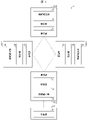
- FIG. 1 is a block diagram showing the configuration of a communication system 1.
- a communication system 1 according to the exemplary embodiment includes multiple communication devices 10 and a control device 20 .
- a plurality of communication devices 10 can configure a mesh network.
- a mesh network includes a first communication device 10-1, a second communication device 10-2, a third communication device 10-3, and a fourth communication device 10-, as shown in FIG. 4, which are configured by connecting these communication devices to each other.
- FIG. 1 the configuration example shown in FIG. 1 is merely an example.
- a configuration including five or more communication devices may be employed, or a configuration including three or less communication devices may be employed.
- the first communication device 10-1, the second communication device 10-2, the third communication device 10-3, and the fourth communication device 10-4 shown in FIG. 1 have the same configuration. . Therefore, one communication device will be taken up and explained as the communication device 10 below.
- the communication device 10 includes a communication unit 11, an identification unit 12, and a connection establishment unit 13, as shown in FIG.
- the communication unit 11, the identification unit 12, and the connection establishment unit 13 are implementation examples of communication means, identification means, and connection establishment means in the scope of claims.
- the communication unit 11 is configured to be able to transmit and receive a directional communication medium.
- the number of communication units 11 included in the communication device 10 does not limit this exemplary embodiment, and the communication device 10 can be configured to include one or more communication units 11 .
- Each communication unit 11 is configured to be able to transmit and receive directional communication media as described above.
- the specific configuration of the communication unit 11 does not limit this exemplary embodiment, but as an example, a transmission unit that transmits a directional communication medium and a and a receiver.
- the communication unit 11 may be configured to include an integrated transmission/reception unit that transmits and receives a directional communication medium.
- Electromagnetic waves in this frequency range may include millimeter waves, sub-millimeter waves, infrared light, visible light, ultraviolet light, and the like.
- the communication unit 11 uses the directional communication medium for communication by orienting the electromagnetic waves in the frequency domain within a predetermined angular range and transmitting the electromagnetic waves.
- the specific configuration for the communication unit 11 to direct the electromagnetic waves in the frequency domain does not limit this exemplary embodiment.
- the communication unit 11 ⁇ Beam forming antenna that directs millimeter waves and sub-millimeter waves within a specified angle range ⁇ Collimator that collimates infrared light, visible light, or ultraviolet light ⁇ Laser of infrared light, visible light, or ultraviolet light
- a configuration including a laser oscillator or the like for generating power can be employed.
- the communication unit 11 directs and sends out electromagnetic waves in the above-mentioned frequency range, which is a communication medium, the energy density of the communication medium increases, so communication can be performed with a distant communication partner using the communication medium. .
- the identification unit 12 identifies one or more connection partner candidates by scanning using the communication unit 11 .
- the specifying unit 12 specifies one or more connection partner candidates by transmitting or receiving scan beams using the communication unit 11 .
- scanning using the communication unit 11 scanning using the above-described directional communication medium is executed.
- scanning in this exemplary embodiment refers, by way of example, to a search performed to identify one or more potential connection partners.
- the word scan is not intended to prescribe a specific scan order or the like.
- the scanning using the communication unit 11 by the specifying unit 12 - Sending a scan beam from the communication unit 11 to the scan range - Sending a scan beam from the communication unit 11 to the scan range and receiving a response beam that is a response to the scan beam, and - Sending from another device
- the communication unit 11 receives the scan beam that has been transmitted from another device, and the communication unit 11 receives the scan beam transmitted from another device and transmits a response beam that is a response to the scan beam.
- Scanning by the identifying unit 12 includes, for example, searching for connection partner candidates whose positions are not known in advance. More specifically, as an example, the scanning by the identification unit 12 includes searching for a connection partner candidate whose direction from the communication device 10 as a starting point is not known in advance. In other words, this includes searching for connection partner candidates for which at least one of the azimuth angle, elevation angle, and depression angle with respect to the communication device 10 is not known in advance.
- the identifying unit 12 When searching for one or more connection partner candidates whose positions are not known in advance as described above, the identifying unit 12 identifies the positions of the one or more connection partner candidates by scanning using the communication unit 11. do. More specifically, as an example, the identification unit 12 identifies the direction from the communication device 10 for the one or more connection partner candidates by scanning using the communication unit 11 . In other words, the specifying unit 12 specifies at least one of the azimuth angle, elevation angle, and depression angle with respect to the communication device 10 for the one or more connection partner candidates by scanning using the communication unit 11 .
- connection partner candidates specified by the specifying unit 12 are not limited to the communication devices included in the scanning range of the scanning using the communication unit 11 .
- the specifying unit 12 refers to the response signal from the communication device included in the scan range of the scan using the communication unit 11, and identifies the communication device specified by the response signal and the communication device outside the scan range. , can also be specified as a connection partner candidate.
- the communication device B whose position is specified by the response signal, and the communication outside the scan range Device B can also be identified as a connection partner candidate.
- connection establishment unit 13 establishes a connection with one or more connection partner candidates identified by the identification unit 12 .
- the connection is established by the connection establishment unit 13 by using the same communication unit as the one or more communication units 11 used by the identification unit 12 for scanning, among the one or more communication units 11 included in the communication device 10.
- a communication unit partially or wholly different from the one or a plurality of communication units 11 used for scanning by the specifying unit 12 may be used.
- connection establishment unit 13 establishes a directional connection with one or more connection partner candidates identified by the identification unit 12 by means of one or more communication units 11 included in the communication device 10.
- a communication medium is used to establish a connection.
- connection establishment processing by the connection establishment unit 13 does not limit this exemplary embodiment, the following processing A is included as an example.
- the communication unit 11 of the communication device 10 transmits a directional communication medium to the connection partner candidate identified by the identification unit 12
- connection establishment process may include the following process B in addition to the process A described above.
- connection partner candidate transmits a directional communication medium to the communication device 10
- the communication unit 11 of the communication device 10 transmits the directional communication medium.
- the communication unit 11 of the communication device 10 may be configured to transmit connection start information for starting connection according to a specific protocol to the connection partner candidate using a directional communication medium.
- the communication unit 11 of the communication device 10 may be configured to receive connection acceptance information according to a specific protocol from the connection partner candidate via a directional communication medium.
- connection initiation information may include identification information for identifying the communication device 10 from other devices, and the connection acceptance information may include identification information for identifying connection partner candidates from other devices. It may be configured to include identification information.
- connection establishment process may include the following processes C and D in addition to the processes A and B described above.
- connection partner candidate refers to the connection start information transmitted by the communication unit 11 of the communication device 10 via the directional communication medium in the processing A, and the connection partner candidate transmits the identification information of the communication device 10 to the connection start information. To be registered in the storage unit provided by the partner candidate
- the communication device 10 refers to the connection approval information received by the communication unit 11 of the communication device 10 through the directional communication medium in the processing B, and stores the connection partner candidates in the storage unit of the communication device 10 itself. to register the identification information of
- connection establishment process may include at least one of the following processes E and F in addition to the processes A, B, C and D described above.
- the communication device 10 transmits to the control device 20 the identification information of the connection partner candidate registered in the processing D.
- control device 20 The control device 20 controls the plurality of communication devices 10 .
- the control of the plurality of communication devices 10 by the control device 20 includes, for example, signals, information, and instructions between the control device 20 and the communication devices 10 via a wired or wireless local area network or global network, or a combination thereof. It is done by exchanging etc.
- These networks may include the mesh network of communication system 1 .
- the control device 20 connects to the mesh network via the second communication device 10-2 and, via the mesh network, to control a plurality of communication devices 10 . Further, the control device 20 may control the plurality of communication devices 10 via another communication path in addition to controlling the plurality of communication devices 10 via the mesh network.
- control device 20 includes a control section 21, as shown in FIG.
- the control unit 21 is an implementation example of the control means in the claims.
- control unit 21 The control unit 21 controls the plurality of communication devices 10 .
- control unit 21 refers to the information managed by the control unit 21 described above, ⁇ Monitoring of each communication device 10 (especially boundary terminal) ⁇ Control of line connection between communication devices 10 ⁇ Update of communication path (including update of priority of communication path) etc.
- control objectives for a plurality of communication devices 10 may include: Support for connection of a new communication device 10 to the mesh network Reconnection of a disconnected line Renewal of a communication path to prevent deterioration of communication quality or disconnection of a line, and the like.
- control unit 21 controls the plurality of communication devices 10 based on the following information.
- ⁇ Network status related to backbone link and access link ⁇ Related information about each communication device 10 (location information, load status, number of established connections, number of identified connection partner candidates, connection status of involved connections, etc.) ⁇ Reference information (weather information, sensor information, etc.)
- the control unit 21 may acquire this information, for example, from each communication device 10 or an external device (not shown).
- the access link mainly refers to a connection path used for exchanging data between edge terminals included in the communication system 1 .
- a backbone link mainly refers to a connection path used for exchanging data between communication devices other than edge terminals included in the communication system 1 . Even a backbone link may function as an access link depending on the situation.
- control unit 21 controls the plurality of communication devices 10 at the following timings. - Timing when a new communication device 10 scans for connection to the mesh network - Timing when the connection status between communication devices 10 within the mesh network changes - Line quality between communication devices 10 within the mesh network Predicted timing of deterioration or line disconnection
- the control unit 21 may detect these timings by monitoring each communication device 10, for example. Also, the control unit 21 may control the plurality of communication devices 10 based on the monitoring results of each communication device 10 at appropriate times instead of at a specific timing.
- the communication system 1 includes a plurality of communication devices (for example, a first communication device 10-1, a second communication device 10-2, a third communication device 10-3, and a fourth communication device device) and the control device 20 .
- the communication device 10 - One or a plurality of communication units 11 configured to be capable of transmitting/receiving a directional communication medium; a specifying unit 12 that specifies one or more connection partner candidates by executing a scan using one or more communication units 11;
- a connection establishing unit 13 that establishes a connection with one or more connection partner candidates identified by the identifying unit 12, and the control device 20 -
- a control unit 21 that controls a mesh network configured by connecting a plurality of communication devices 10 to each other is adopted.
- each communication device 10 can identify even a connection partner candidate whose position is not known in advance by executing a scan using the communication unit 11. can be done. Then, communication can be established with the specified connection partner candidate.
- directional communication media can achieve high-capacity and low-delay communication, but because they are directional, they are susceptible to obstructions and disturbances.
- the communication device 10 it is possible to make adaptive changes including addition of communication devices and change of positions in a network using a directional communication medium. It is possible to construct a network that is not easily affected by obstacles, disturbances, and the like.
- control device 20 can improve network stability by controlling a plurality of communication devices 10 .
- the communication system 1 according to this exemplary embodiment, it is possible to realize a robust communication network using a directional communication medium.
- control device 20 is a control device 20 that controls a plurality of communication devices 10 capable of forming a mesh network, and each of the plurality of communication devices performs directional communication.
- one or more communication means configured to be able to transmit and receive a medium; an identification means for identifying one or more connection partner candidates by executing a scan using the one or more communication means; a connection establishing means for establishing a connection with one or more connection partner candidates identified by the means; .
- control is performed on a plurality of communication devices 10 capable of forming a mesh network.
- Each of the plurality of communication devices 10 can identify a connection partner candidate whose position is not known in advance by executing a scan using the communication unit 11 . Then, each of the plurality of communication devices 10 can establish communication with the specified connection partner candidate.
- the control device 20 can improve the stability of the mesh network by controlling such multiple communication devices 10 .
- control device 20 it is possible to realize a robust communication network using a directional communication medium, like the communication system 1 according to this exemplary embodiment.
- FIG. 2 is a flow diagram illustrating a control method for the communication system 1 according to this exemplary embodiment.
- the control method of the communication system 1 includes steps S12 and S13 executed by the communication device 10 and step S21 executed by the control device 20 .
- the communication system 1 includes a plurality of communication devices 10 capable of forming a mesh network and a control device 20 that controls the plurality of communication devices 10 .
- Step S12 First, in step S ⁇ b>12 , the identification unit 12 identifies one or more connection partner candidates by executing a scan using the communication unit 11 .
- the scan using the communication unit 11 the scan using the above-described directional communication medium is executed. Since the specific processing contents by the identifying unit 12 have been described above, the description thereof is omitted here.
- connection establishment unit 13 establishes a connection with one or more connection partner candidates identified by the identification unit 12 .
- the connection is established by the connection establishment unit 13 by using the same communication unit as the one or more communication units 11 used by the identification unit 12 for scanning, among the one or more communication units 11 included in the communication device 10.
- a communication unit partially or wholly different from the one or a plurality of communication units 11 used for scanning by the specifying unit 12 may be used. Since the specific processing contents of the connection establishing unit 13 have been described above, the description thereof is omitted here.
- Step S21 Step S21 is performed before or after steps S12 and S13, or in parallel with steps S12 and S13.
- the control unit 21 controls the plurality of communication devices 10 . Since the specific processing contents of the control unit 21 have been described above, the description thereof is omitted here.
- each of the plurality of communication devices 10 scans using a directional communication medium to Identifying a candidate (S12), establishing a connection with one or more identified connection partner candidates (S13), and controlling a plurality of communication devices 10 by the control device 20 ( S21).
- each of the plurality of communication devices 10 performs scanning using the communication unit 11 even for a connection partner candidate whose position is not known in advance. can be identified by Then, each of the plurality of communication devices 10 can establish communication with the identified connection partner candidate.
- the stability of the mesh network can be improved.
- control method of the communication system 1 according to this exemplary embodiment like the communication system 1 according to this exemplary embodiment, it is possible to realize a robust communication network using a directional communication medium. can be done.
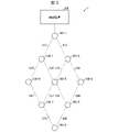
- FIG. 3 is a diagram showing a configuration example of the communication system 1 according to this exemplary embodiment.
- the communication system 1 includes a control device 200 and a plurality of communication devices (communication devices 100-0 to 100-8 in FIG. 3). These communication devices 100-0 to 100-8 have the same configuration. Therefore, one communication device will be taken up and explained as the communication device 100 below.
- dotted lines indicate established connections.
- the code "Cxy" (where x and y are numbers) indicates the connection established between the communication device 100-x and the communication device 100-y.
- C12 refers to the connection established between communication device 100-1 and communication device 100-2.
- each communication device included in the communication system 1 constitutes a mesh network having communication paths laid out like a mesh.
- any one of the communication devices 100-0 to 100-8 may function as an edge terminal, and the communication system 1 may include any of the communication devices other than the communication devices shown in FIG.
- the configuration may include one or a plurality of edge terminals connected to each other.
- an edge terminal refers to a terminal that serves as a terminal of an access link in the mesh network of the communication system 1.
- Examples of edge terminals include a communication terminal connected to a network other than the communication system 1, a user terminal used by a user, and the like.
- FIG. 4 is a block diagram showing the configuration of the communication device 100. As shown in FIG.
- the communication device 100 includes a first communication section 110, a second communication section 120, a control section 130, a memory 140, and a storage section 150.
- the first communication unit 110 is an implementation example of communication means in the claims.
- the first communication unit 110 is configured to be able to transmit and receive a directional communication medium.
- the first communication unit 110 is composed of a plurality of communication units such as a communication unit 110-1, a communication unit 110-2, . . . as shown in FIG.
- the individual communication units 110-1, 110-2, . . . are configured to be able to transmit and receive directional communication media as described above.
- the specific configurations of the individual communication units 110-1, 110-2, . . . do not limit this exemplary embodiment. and a receiver for receiving a directional communication medium.
- a specific example of the directional communication medium used for communication by the first communication unit 110 does not limit the exemplary embodiment, but as an example, similar to the exemplary embodiment 1, generally An electromagnetic wave in a high frequency region having a frequency of 10 GHz or higher can be cited as an example. Electromagnetic waves in this frequency range may include millimeter waves, sub-millimeter waves, infrared light, visible light, ultraviolet light, and the like.
- the first communication unit 110 uses the above-described directional communication medium for communication by directing and transmitting electromagnetic waves in the frequency domain within a predetermined angular range.
- the specific configuration for directing the electromagnetic wave in the frequency domain by the first communication unit 110 does not limit this exemplary embodiment.
- a configuration including a laser oscillator or the like for generating power can be employed.
- the individual communication units 110-1, 110-2 transmits/receives an azimuth angle range of 0° to 90°
- the communication unit 110-2 transmits/receives an azimuth angle range of 90° to 180°
- the communication unit 110- 3 may be oriented to transmit and receive in an azimuth range of 180° to 270°
- the communication unit 110-4 may be oriented to transmit and receive in an azimuth range of 270° to 360°.
- the 2nd communication part 120 is the structure which communicates using communication media other than the directional communication medium which the 1st communication part 110 uses for communication.
- the second communication unit 120 communicates with other devices via a wired or wireless local area network, global network, or the like.
- the second communication unit 120 may communicate with the control device 200 .
- the control unit 130 includes an acquisition unit 131, a communication management unit 132, and a storage management unit 133, as shown in FIG.
- the communication management unit 132 is an implementation example of specifying means and connection establishing means in the claims.
- Acquisition unit 131 acquires related information related to a communication partner by first communication unit 110 .
- the communication partner by the first communication unit 110 - One or a plurality of connection partner candidates identified by the communication management unit 132 (to be described later) by scanning using the first communication unit 110 established connection partners.
- the related information acquired by the acquisition unit 131 will be described later.
- the communication management section 132 manages communication processing using the first communication section 110 .
- the communication management unit 132 ⁇ Scanning using the first communication unit 110 ⁇ Establishing a connection using the first communication unit 110 ⁇ Disconnecting the connection using the first communication unit 110 ⁇ Switching the connection using the first communication unit 110 etc. are processed. A specific example of processing by the communication management unit 132 will be described later.
- the storage management unit 133 manages storage processing to the storage unit 150 .
- the storage management unit 133 stores the related information acquired by the acquisition unit 131 in the storage unit 150 .
- the storage management unit 133 reads out various information stored in the storage unit 150 and provides it to each unit of the control unit 130 .
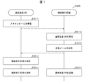
- FIG. 5 is a sequence diagram showing a first example of the flow of processing from scanning using the first communication unit 110 by the communication management unit 132 to connection establishment.
- the communication device 100 first emits a scan beam and establishes a connection with a connection partner candidate existing within the scan target range.
- Step S101-1 the communication management unit 132 uses the first communication unit 110 to transmit a scan beam targeting a predetermined scan range.
- the transmitted scan beam reaches a connection partner candidate existing in the scan range.
- Step S101-2 a connection partner candidate existing within the scanning range returns a response beam to communication apparatus 100 as a response to the scanning beam.
- the returned response beam reaches the communication device 100 .
- connection partner candidate may include a corner cube reflector, reflect the scan beam by the corner cube reflector, and return the reflected scan beam to the communication device 100 as a response beam.
- the connection partner candidate may be configured to include a receiving device that receives the scan beam and a transmitting device that transmits the response beam in the receiving direction.
- Step S102-1 the communication management unit 132 refers to the response beam received from the connection partner candidate and identifies the communication partner candidate.
- the communication management unit 132 identifies the position of the connection partner candidate based on the direction of the received response beam. More specifically, the communication manager 132 identifies the direction of the connection partner candidate viewed from the communication device 100 based on the direction of the received response beam. In other words, the communication management unit 132 identifies at least one of the azimuth, elevation, and depression angles of the connection partner candidate viewed from the communication device 100 based on the direction of the received response beam.
- Step S103-1 the communication manager 132 transmits a connection request beam to the connection partner candidate identified in step S102-1.
- the connection request beam may include identification information for identifying the communication device 100 from other devices together with information indicating that a connection is requested.
- the connection request beam may include related information managed by the storage management unit 133, which is related to the communication device 100 and other communication devices.
- connection partner candidate receives the connection request beam transmitted in step S103-1. Also, the connection partner candidate identifies communication apparatus 100 by referring to the connection request beam transmitted in step S103-1. As an example, the connection partner candidate identifies the position of the communication device 100 based on the direction of the received connection request beam. More specifically, the connection partner candidate identifies the direction of communication apparatus 100 as seen from the connection partner candidate based on the direction of the received connection request beam. In other words, the connection partner candidate specifies at least one of the azimuth angle, elevation angle, and depression angle of the communication device 100 seen from the connection partner candidate based on the direction of the received connection request beam.
- connection partner candidate transmits a connection acceptance beam to communication apparatus 100.
- the connection acknowledgment beam may include information to the effect that the connection is accepted and identification information for identifying the connection partner candidate from other devices. Further, the connection approval beam may include related information about the connection partner candidate and other communication devices.
- Step S104-1 the communication manager 132 receives the connection approval beam transmitted in step S103-2.
- Step S105-1 the storage management unit 133 refers to the connection acceptance beam received in step S104-1, and registers the connection partner candidate as a connection partner.
- the storage management unit 133 stores the identification information of the connection partner candidate included in the connection approval beam in the storage unit.
- this step establishes a connection from the communication device 100 to the connection partner candidate.
- connection partner candidate refers to the connection request beam received in step S102-2 and registers communication device 100 as a connection partner.
- the connection partner candidate stores the identification information of the communication device 100 included in the connection request beam in a storage unit included in the connection partner candidate.
- this step establishes a connection from the connection partner candidate to the communication device 100 .
- FIG. 6 is a sequence diagram showing a second example of the flow of processing from scanning using the first communication unit 110 by the communication management unit 132 to connection establishment.
- the connection partner candidate first emits a scan beam and establishes a connection with the communication device 100 existing within the scan target range.
- the flow processing from scanning to connection establishment according to this example is similar to the connection processing between the communication device 100 and the connection partner candidate described with reference to FIG. is replaced. Since the processing in each step shown in FIG. 6 is clear by referring to FIG. 5, detailed description thereof is omitted here.
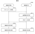
- FIG. 7 is a sequence diagram showing a third example of the flow of processing from scanning using the first communication unit 110 by the communication management unit 132 to connection establishment.
- the communication device 100 first emits a scan beam and establishes a connection with a connection partner candidate existing within the scan target range.
- Step S121-1 the communication management unit 132 uses the first communication unit 110 to transmit a scan beam targeting a predetermined scan range.
- the transmitted scan beam reaches a connection partner candidate existing in the scan range.
- the scan beam transmitted in this step may be configured to include identification information for identifying the communication device 100 from other devices together with information requesting connection. Further, the scan beam may include related information managed by the storage management unit 133, which is related to the communication device 100 and other communication devices.
- the connection partner candidate refers to the scan beam transmitted in step S121-1 and identifies communication device 100.
- FIG. the connection partner candidate identifies the position of communication device 100 based on the direction of the scan beam transmitted in step S121-1. More specifically, the connection partner candidate identifies the direction of communication apparatus 100 seen from the connection partner candidate based on the direction of the received scan beam. In other words, the connection partner candidate identifies at least one of the azimuth, elevation angle, and depression angle of the communication device 100 viewed from the connection partner candidate based on the direction of the received scan beam.
- connection partner candidate may further refer to the identification information of the communication device 100 included in the scan beam to specify the communication device 100 .
- Step S122-2 the connection partner candidate transmits a response beam to communication apparatus 100 as a response to the scan beam transmitted in S121-2.
- the transmitted response beam reaches the communication device 100 .
- the response beam transmitted in this step may include identification information for identifying the connection partner candidate from other devices together with information to the effect that the connection is accepted. Further, the response beam may include relevant information managed by the connection partner candidate and related information relating to the connection partner candidate and other communication devices.
- Step S122-1) the communication management unit 132 refers to the response beam transmitted in step S122-2 to identify connection partner candidates.
- the communication management unit 132 identifies the position of the connection partner candidate based on the direction of the received response beam. More specifically, the communication manager 132 identifies the direction of the connection partner candidate viewed from the communication device 100 based on the direction of the received response beam. In other words, the communication management unit 132 identifies at least one of the azimuth, elevation, and depression angles of the connection partner candidate viewed from the communication device 100 based on the direction of the received response beam.
- the communication management unit 132 may further refer to the identification information of the connection partner candidate included in the response beam to specify the connection partner candidate.
- Step S123-1 the storage management unit 133 refers to the response beam received from the connection partner candidate and registers the connection partner candidate as a connection partner.
- the storage management unit 133 stores the identification information of the connection partner candidate included in the response beam in the storage unit.
- this step establishes a connection from the communication device 100 to the connection partner candidate.
- connection partner candidate refers to the scan beam received from communication device 100 and registers communication device 100 as a connection partner.
- the connection partner candidate stores the identification information of the communication device 100 included in the scan beam in a storage unit included in the connection partner candidate.
- this step establishes a connection from the connection partner candidate to the communication device 100 .
- FIG. 8 is a sequence diagram showing a fourth example of the flow of processing from scanning using the first communication unit 110 by the communication management unit 132 to connection establishment.
- the connection partner candidate first emits a scan beam and establishes a connection with the communication device 100 existing within the scan target range.
- the flow processing from scanning to connection establishment according to this example is similar to the connection processing between the communication device 100 and the connection partner candidate described with reference to FIG. is replaced. Since the processing in each step shown in FIG. 8 is clear by referring to FIG. 7, detailed description thereof is omitted here.
- the communication device 100 has a communication partner candidate (referred to as a communication partner candidate B ) to establish a connection.
- a communication partner candidate B a communication partner candidate to establish a connection.
- communication device 100 refers to the relevant information included in the connection request beam transmitted in step S113-2, identifies communication partner candidate B, and identifies communication partner candidate B. It may be configured to establish a connection between.
- the communication apparatus 100 uses a communication partner candidate (for convenience, called communication partner candidate B) that is different from the communication partner candidate that transmitted the scan beam (for convenience, called communication partner candidate A). ) to establish a connection.
- communication partner candidate B for convenience, called communication partner candidate B
- communication partner candidate A the communication partner candidate that transmitted the scan beam
- communication device 100 refers to the related information included in the scan beam transmitted in step S131-2, identifies communication partner candidate B, and communicates with the identified communication partner candidate B. It is also possible to establish a connection with .
- the acquisition unit 131 included in the communication device 100 acquires related information related to the communication partner device of the communication device 100, and the storage management unit 133 included in the communication device 100 stores the related information acquired by the acquisition unit 131 in the storage unit. 150 and managed.
- the communication partner of the communication device 100 is at least one or more connection partner candidates identified by the communication management unit 132, and one or more connection partners already established by the communication management unit 132. is included.
- the storage management unit 133 can also be configured to store and manage related information related to the communication device 100 in the storage unit 150 .
- communication device A one of the plurality of communication devices
- communication devices B, C, and D exist as communication partners of communication device A
- related information of communication device A Explain the contents.
- Each of the communication devices A, B, C, and D is one of the communication devices 100-0 to 100-8 shown in FIG. 3, for example.
- the related information of communication device A includes: - Location information of the communication device A, and - Load status of communication device A - Number of established connections involving communication device A, - The number of identified connection partner candidates in which communication device A is involved, - The connection status of the connection in which the communication device A is involved - At least one of the number of hops from the communication device A to the connection reference point is included.
- the location information of the communication device A does not limit this exemplary embodiment, but as an example, it may be coordinate information given by a predetermined location specifying system such as GPS. , position identification information such as an address assigned in advance within the target communication area, or information indicating the direction of the communication device A as seen from the communication devices around the communication device A. .
- the specific index of the load status of communication device A does not limit this exemplary embodiment.
- it may be information indicating the operating rate of a processor such as a control unit provided in communication device A, or information indicating the operating rate of a specific task by a processor such as a control unit provided in communication device A. good.
- connection involving the communication device A includes at least one of a connection originating from or ending at the communication device A, and a connection via the communication device A.
- the connections involving communication device A include the connection between communication device A and communication device B, the connection between communication device A and communication device C, and the connection between communication device A and communication device A. At least some of the connections to and from device D are included.
- connection status of the connection involving the above-described communication partner A includes: At least one of: - the line quality of the connection involving the communication device A;
- the specific index regarding the line quality of the connection involving the communication device A does not limit this exemplary embodiment, but as an example, the delay in communication due to the connection and the It includes any measure, such as information loss rate.
- an index regarding the number of disconnections of the connection involving the communication device A does not limit this exemplary embodiment, as an example, an index regarding the number of disconnections per unit time of communication through the connection is used. contains.
- the related information of the communication device A includes: • A configuration may be adopted in which information regarding the environmental influence on the connection involving the communication device A is included.
- the information about the environmental influence on the connection involving the communication device A includes: ⁇ Influence of sunlight on connection between communication device A and communication device B ⁇ Influence of sunlight on connection between communication device A and communication device C At least one of the influence of sunlight on connection is included.
- the degree of influence of sunlight on a certain connection can be expressed, for example, by the angle of the direction of the sun relative to the direction along the certain connection. For example, if the angle between the direction along the connection and the sun direction is close to 90°, the influence information indicates that the influence of sunlight on the connection is relatively small. Also for example, if the angle between the direction along the connection and the sun direction is close to 0°, the influence information indicates that the influence of sunlight on the connection is relatively large.
- the information about the influence of the environment on the connection involving the communication device A includes information indicating the influence of reflection and absorption on the directional communication medium used by the communication unit of the communication device A.
- the configuration may include information such as the transparency of the air and information such as buildings near the propagation path.
- FIG. 9 is a block diagram showing the configuration of the control device 200.
- the control device 200 according to this exemplary embodiment comprises a control section 210, a memory 220, a storage section 230, and a communication section 240.
- FIG. 9 is a block diagram showing the configuration of the control device 200.
- the control device 200 according to this exemplary embodiment comprises a control section 210, a memory 220, a storage section 230, and a communication section 240.
- the control unit 210 includes an acquisition unit 211, a communication management unit 212, a storage management unit 213, and an instruction unit 214, as shown in FIG.
- Acquisition unit 211 is an implementation example of acquisition means in the claims.
- the storage management unit 133 is an implementation example of storage means in the claims.
- the acquisition unit 211 acquires related information related to each communication device 100 from each communication device 100 .
- the acquisition unit 211 acquires related information acquired by the acquisition unit 131 of the control unit 130 included in each communication device 100 .
- Related information related to each communication device 100 may include at least one of the following related information, as exemplified above.
- - Location information of the communication device 100 Load status of the communication device 100 - Number of established connections involving the communication device 100 - Connection status of connections involving the communication device 100 - Line quality of connections involving the communication device 100 - Communication Information about the number of interruptions of connections involving the device 100 and the environmental influences on the connections involving the communication device 100 .
- connection status of the connection involving the communication device 100 includes: - The connection status of the access link in which the communication device 100 is involved - The connection status of the backbone link in which the communication device 100 is involved is included.
- the information about the environmental influence on the connection involving the communication device 100 includes: Information about the influence of sunlight on the connection involving the communication device 100 and the influence of reflected light on the connection involving the communication device 100 is included.
- the acquisition unit 211 may further acquire the following reference information. ⁇ Weather information and sensor information.
- the acquisition unit 211 may acquire weather information from an external server device that provides weather information.
- the acquisition unit 211 may acquire sensor information from an external field sensor.
- the field sensor general field sensors that sense the environment can be used.
- the communication management unit 212 manages communication processing using the communication unit 240, and manages transmission and reception with the communication devices 100-0 to 100-8.
- the communication management unit 212 may set communication paths.
- the communication management unit 212 refers to the related information acquired by the acquisition unit 211 to obtain the second communication device from the first communication device 100.
- a communication route to the communication device 100 is set and an instruction is given to each communication device 100 .
- the communication management unit 212 gives priority to one or a plurality of communication paths included in the mesh network by referring to related information related to the communication device 100 involved in the communication path. Even if the communication path to which the priority is given according to the priority, such as resetting the communication path from the communication device 100 to the second communication device 100 to a communication path with a high priority good.
- the communication management unit 212 may refer to the related information acquired by the acquisition unit 211 and monitor at least one communication device 100 among the plurality of communication devices 100 .
- the communication management unit 212 refers to the related information acquired by the acquisition unit 211 and refers to at least one communication device 100 out of the plurality of communication devices 100 or an event that occurred in a connection involving the communication device 100. to detect
- Events detected by the communication management unit 212 include: - Degradation of line quality - Disconnection of line - Detection of scan by new communication device 100 - Establishment of new connection, etc.
- the communication management unit 212 ⁇ Scan using the communication device 100 ⁇ Establishing a connection using the communication device 100 ⁇ Disconnecting a connection using the communication device 100 ⁇ Switching the connection using the communication device 100 ⁇ Processing such as updating a communication path Point to 100.
- the communication management unit 212 may update the communication route so as to bypass the degraded line when detecting deterioration of the line quality, or may reconnect when detecting disconnection of the line. may be instructed to the communication device 100 to scan for and establish a connection.
- the communication route is adjusted so as to optimize the mesh network including the new communication device 100.
- the communication device 100 may be instructed to update, disconnect, switch, and the like.
- the storage management unit 213 manages storage processing to the storage unit 230 .
- the storage management unit 213 causes the storage unit 230 to store the related information acquired by the acquisition unit 211 .
- the storage management unit 213 reads out various information stored in the storage unit 230 and provides it to each unit of the control unit 210 .
- the storage management unit 213 causes the storage unit 230 to store reference information and correlation information, which will be described later, in addition to accumulating the acquired related information.
- the instruction unit 214 generates instruction information for controlling the communication devices 100-0 to 100-8 based on the processing result of the communication management unit 212.
- FIG. 21 Instruction unit 214.
- Storage unit 230 stores the related information acquired by acquisition unit 211 .
- the storage unit 230 further stores reference information.
- the storage unit 230 further stores correlation information.
- the correlation information is information indicating the correlation between the reference information described above and the related information of each communication device 100, particularly the line quality of each communication device 100, the number of interruptions within a specified time period, and the like.
- the communication unit 240 is configured to perform communication using a communication medium other than the directional communication medium used for mutual communication by the first communication unit 110 (FIG. 4) of each communication device. communication with the second communication unit 120 (FIG. 4).
- communication via a wired or wireless local area network, global network, or the like can be adopted.
- control unit 210 refers to the related information acquired by the acquisition unit 211, monitors at least one communication device 100 among the plurality of communication devices 100, and controls line connection according to the monitoring result. may be performed.
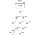
- FIG. 10 is a diagram for explaining an example of a state in which a new terminal is attempting to connect to the mesh network controlled by the control device 200.
- FIG. 10 is a diagram for explaining an example of a state in which a new terminal is attempting to connect to the mesh network controlled by the control device 200.
- the communication device 100-A is trying to connect to the mesh network configured by the communication devices 100-0 to 100-8.
- the communication management unit 212 gives priority to the connection partner candidates specified by the communication management unit 132 of the new terminal (communication device 100-A) by referring to related information related to each connection partner candidate,
- the connection may be controlled by the communication manager 132 of the communication device 100-A.
- the communication management unit 212 performs a connection simulation when adding a new terminal (communication device 100-A) to the mesh network.
- the communication management unit 212 may refer to the line quality of the connection among the related information and lower the priority of the route with poor line quality.
- the communication device 100-A is instructed to establish a high-priority connection (for example, connection with the communication device 100-0).
- the instruction may be included in the scan information transmitted from communication device 100-0 to communication device 100-A.
- the communication management unit 212 may set priority settings according to the time of day for connections that are susceptible to the effects of sunlight depending on the time of day. As a result, when establishing a connection with a new terminal (communication device), a line suitable for connection can be selected and a smooth connection can be realized.
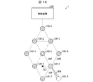
- FIG. 11 is a diagram for explaining an example of a state in which a new terminal is attempting to connect to the mesh network controlled by the control device 200.
- FIG. 11 is a diagram for explaining an example of a state in which a new terminal is attempting to connect to the mesh network controlled by the control device 200.
- another network controlled by the control device 200A is connected to the mesh network configured by the communication devices 100-0 to 100-8.
- the communication device 100-A is trying to connect to the mesh network configured by the communication devices 100-0 to 100-8.
- the other network is not particularly limited, and may be an existing optical fiber network or the like.
- communication devices 100-3, 100-6, and 100-7 are border terminals existing on the border with another network (B network).
- the communication manager 212 may focus on monitoring such border terminals. This is because there is a high possibility that the traffic load will increase for the communication device that performs the boundary connection.
- the communication management unit 212 simulates a load increase of the boundary terminal when adding a new terminal (communication device 100-A) to the mesh network. For example, the communication management unit 212 estimates an increase in communication traffic with other networks due to the addition of the communication device 100-A, and estimates an increase in the load on the boundary terminal due to the increase in communication traffic. . The communication management unit 212 may determine whether or not to add a boundary terminal connected to another network or change the connection path based on the amount of increase in the load on the boundary terminal, and may instruct each communication device 100 to do so. .
- control unit 210 may acquire a connection request from a new terminal attempting to newly connect to the mesh network, and control the connection of the new terminal.
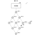
- FIG. 12 is a diagram for explaining an example of a state in which a new terminal is trying to connect to the mesh network controlled by the control device 200.
- FIG. 12 is a diagram for explaining an example of a state in which a new terminal is trying to connect to the mesh network controlled by the control device 200.
- a new terminal 100-A that attempts to newly connect to the mesh network sends a connection request including the terminal coordinates of the new terminal 100-A to the control device 200 using an existing line CA that is different from the mesh network. to notify. Thereby, the acquisition unit 211 of the control device 200 acquires the connection request including the terminal coordinates.
- the communication management unit 212 selects at least one communication device 100 (for example, communication device 100-0) in the mesh network to be connected to the new terminal based on related information stored in the storage unit 230. identify. As an example, the communication management unit 212 identifies the communication device 100-0 located near the new terminal 100-A based on related information and the like.
- the instruction unit 214 instructs the specified communication device 100 (for example, the communication device 100-0) to connect.
- the instruction unit 214 instructs the specified communication device 100 including the terminal coordinates of the new terminal 100-A.
- the communication device 100 that has received the connection request instruction refers to the terminal coordinates of the new terminal 100-A and transmits a scan beam S0A in the direction of the new terminal.
- the new terminal 100-A receives the scan beam S0A, returns a response beam, and establishes a connection with the communication device 100.
- the terminal coordinates of the new terminal can be notified to the control device 200, and a scan beam can be transmitted in the direction of the new terminal.
- the search range for scanning can be narrowed down, and the search can be completed in a short period of time.
- control unit 210 acquires a request from the communication device 100 that has received a scan signal from a new terminal attempting to newly connect to the mesh network, and updates the communication path.
- FIG. 13 is a diagram for explaining an example of a state in which a new terminal is attempting to connect to the mesh network controlled by the control device 200.
- FIG. 13 is a diagram for explaining an example of a state in which a new terminal is attempting to connect to the mesh network controlled by the control device 200.
- a new terminal (communication device 100-A) attempting to newly connect to the mesh network emits a scan beam S0A within a predetermined range.
- the communication devices 100 (communication devices 100-0 and 100-8) that have received the scan beam S0A transmit communication device request information to the control device 200.
- the acquisition unit 211 acquires the request information.
- the communication management unit 212 updates one or more communication paths included in the mesh network according to the request information.
- the communication management unit 212 obtains related information related to the new terminal 100-A from the new terminal 100-A, and refers to the related information stored in the storage unit 230 together with the related information to determine whether the new terminal communicates with the new terminal 100-A.
- One or more communication paths included in a mesh network formed by communication devices used for data transmission of the device 100-A are updated to be optimized.
- Optimizing communication paths means that in a mesh network, when each communication device has the ability to select multiple communication paths, all communication devices can be connected and even if a disconnection occurs due to a failure or the like, It means shaping communication paths to enable data transmission for users connected to the access network with robust management and switching.
- control unit 210 may manage the number of connections that can be established and the number of established connections for each of one or more communication devices 100 included in the mesh network.
- FIG. 14 is a diagram for explaining an example of a state in which a new terminal is attempting to connect to the mesh network controlled by the control device 200.
- FIG. 14 is a diagram for explaining an example of a state in which a new terminal is attempting to connect to the mesh network controlled by the control device 200.
- the communication management unit 212 for each of one or more communication devices included in the mesh network, • Manage the number of connections that can be established and • the number of connections that have been established.
- the number of connections that can be established is the sum of the number of lines that can be established even though communication has not been established and the number of lines that have communication established (maximum number).
- the number of connections that can be established is also the number of connection partner candidates specified by the communication management unit 132 of the communication device 100 .
- the number of established connections is the number of lines for which communication has been established.
- the communication manager 212 determines that the number of established connections for each of the one or more communication devices included in the mesh network is the maximum number of connections that can be established minus one.
- One or more communication paths included in the mesh network are updated as follows. For example, in each communication device 100, when all of the connections that can be established are established and used as communication paths, the communication management unit 212 prevents one or more communication paths from passing through the communication device 100. By updating, the number of established connections is controlled to be equal to or less than the maximum number of connections that can be established minus one.
- the communication management unit 212 gives priority to one or more communication paths included in the mesh network by referring to related information related to communication devices involved in the communication paths. Priority is given relative to the strength of connection, the presence or absence of alternative communication paths, the number of alternative communication paths, and the like. Information on the priority associated with each communication path is stored in the storage unit 230 as reference information.
- the communication management unit 212 uses a communication path with a high priority so that the number of established connections is equal to or less than the maximum number of connections that can be established minus 1. You can do routing.
- the scan beam can be transmitted to the new terminal 100-A that is about to be newly connected to the mesh network using the available line. can be done.
- the new terminal 100-A is attempting to connect to the mesh network, and the number of established connections of the communication device 100 to which the new terminal 100-A attempts to connect is the maximum number of connections that can be established. If it is the number, the communication management unit 212 may perform a process of disconnecting a communication path with a relatively low priority among one or more communication paths included in the mesh network. This allows the number of established connections to be less than or equal to the maximum number of connections that can be established minus one. The communication management unit 212 instructs, via the instructing unit 214, the communication device constituting the communication path to be disconnected to disconnect the communication path having a relatively low priority.
- the communication management unit 212 sets the number of connections that can be established (maximum number) to "4" for the communication device 100, for example.
- - Established connection is "4" (circuits C07, C05, C06, C08 of established connections with communication devices 100-7, 100-5, 100-6, 100-8) specify that When specified in this way, the communication management unit 212 refers to the reference information in the storage unit 230, compares the priority of each of the lines C07, C05, C06, and C08, and specifies a line that is a relatively low communication route. do.
- line C07 is identified as a communication path with a relatively low priority.
- the communication management unit 212 instructs the communication device 100-0 configuring the line C07 via the instruction unit 214 to disconnect the line C07.
- the communication device 100-0 ⁇ Set the number of connections that can be established (maximum number) to "4" - The number of established connections is "3" Thus, "1" is generated for a connection that can be established but has not been established.
- This connection line means a so-called idle line.
- the vacant line can be used to transmit a scan beam to a new terminal 100-A that is about to be newly connected to the mesh network. conduct.
- the new terminal 100-A is attempting to connect to the mesh network, and the number of established connections of the communication device 100 to which the new terminal 100-A attempts to connect is the maximum number of connections that can be established. number, the communication management unit 212 should add additional new terminals (relay terminals) so as to increase the maximum number of connections that can be established by one or more communication devices 100 included in the mesh network. The administrator of the mesh network or the like may be notified of the fact. As an example, the communication management unit 212 may simulate at what position the relay terminal should be additionally arranged, and notify the result of the simulation.
- each communication device 100 scan and increase the maximum number of connections that can be established. This allows the number of established connections to be less than or equal to the maximum number of connections that can be established minus one.
- the communication management unit 212 for example, regarding the communication device 100-0, - Set the number of connections that can be established (maximum number) to "3" - The number of established connections is "3" , the communication device 100-0 is instructed to rescan, and as a result, the connection line that can be established but has not been established in the communication device 100-0 becomes "1". The communication management unit 212 instructs the communication device 100-0 to establish a connection with the new communication device 100-A using the connection "1".
- control unit 210 instructs one or more communication devices 100 involved in the disconnected connection to restart the connection. Establishment may be indicated.
- FIG. 15 is a diagram for explaining an example of a state in which a line disconnection has occurred in the mesh network controlled by the control device 200.
- FIG. 15 is a diagram for explaining an example of a state in which a line disconnection has occurred in the mesh network controlled by the control device 200.
- the communication management unit 212 of each communication device forming the mesh network, • Manages the number of established connections.
- the communication management unit 212 can also manage whether or not one or more connections included in the established connections have been disconnected. Therefore, when one or more connections included in an established connection are disconnected, the communication management unit 212 instructs one or more communication devices involved in the disconnected connection to re-establish the connection. to direct.
- the instruction itself to the communication device is performed by the instruction unit 214 .
- the communication management unit 212 instructs one or more communication devices involved in the disconnected connection to re-establish the connection. Therefore, the communication management unit 212 manages communication paths so that each communication device can always be connected via two or more communication paths.
- the communication management unit 212 manages the communication device 100-6 to be connected to the first system of the circuits C13 and C36 and the second system of the circuits C12, C25, C05 and C06.
- the communication management unit 212 uses the second system to instruct the communication device 100-6 to transmit the scan beam S63, thereby reconnecting the circuit C36. Plan.
- communication management unit 212 sends terminal coordinate information of communication device 100-3 to communication device 100-6. By designating the terminal coordinate information of the communication device in this manner, reconnection is possible even if the connection is interrupted.
- the communication management unit 212 can instruct reconnection even in such cases.
- the communication management unit 212 when the communication management unit 212 identifies that the circuits C06, C89, C910, C011, and C1011 are disconnected, the communication management unit 212 refers to related information and calculates connectable communication paths.
- the communication management unit 212 sends a connection instruction via the instruction unit 214 to the communication device (for example, the communication device 100-0) with which the communication path is secured.
- the communication device 100-0 that has received the connection instruction transmits a scan beam S09 to the communication device 100-9 to establish a connection.
- the communication management unit 212 manages the terminal coordinates of each communication device. As a result, even when a disconnection occurs, it is possible to transmit a scan beam toward the communication device to be reconnected.
- the communication device 100-0 may also transmit the scan beam to the communication device 100-11.
- control device of this exemplary embodiment allows reconnection to one or more communication devices involved in a broken connection, thus realizing a robust mesh network. can be done.
- control unit 210 acquires related information related to the communication device from one or more communication devices included in the mesh network, acquires reference information different from the related information, and obtains the related information and A correlation with reference information may be calculated, and correlation information indicating the calculated correlation may be accumulated.
- the acquisition unit 211 of the control unit 210 acquires related information.
- the related information acquired by the acquisition unit 211 is It may include at least one of: - the line quality of the connection involving the communication device; and - the number of interruptions of the connection involving the communication device.
- the acquisition unit 211 of the control unit 210 acquires reference information different from the related information.
- the reference information acquired by the acquisition unit 211 is At least one of weather information and sensor information acquired by one or more external sensors 300 may be included.
- the weather information is acquired by the acquisition unit 211 via communication means different from the mesh network.
- the sensor 300 may be a general field sensor that senses the environment, but may also be one that senses the amount of sunlight, air pressure, temperature, and the like.
- the sensor 300 sends sensor information to the control device 200 via the mesh network.
- the storage management unit 213 of the control unit 210 calculates the correlation between the related information and the reference information.
- the correlation information is stored in the storage unit 230 by the storage management unit 213 .
- the method by which the storage management unit 213 calculates the correlation between the related information and the reference information is not particularly limited.
- the memory management unit 213 can be configured to calculate the correlation between the relevant information and the reference information using algorithms such as regression analysis, support vector machine, and principal component analysis.
- the communication management unit 212 can predict various related information.
- a route can be updated (changed).
- the communication management unit 212 may predict the temporal regularity of related information.
- the communication management unit 212 By referring to the correlation information between the relevant information, which is at least one of the line quality of the connection in which each communication device 100 is involved and the number of interruptions in the connection in which each communication device 100 is involved, and the reference information, the relevant information and update (change) the communication route so as not to include the communication device 100 or connection for which the deterioration of the line quality or the increase in the number of interruptions is predicted.
- the communication management unit 212 may update (change) the communication path based on the prediction result of related information such as the load status of each communication device 10 . That is, the communication management unit 212 is an implementation example of updating means in the claims.
- the communication management unit 212 refers to the correlation information and predicts a drop in line quality or disconnection of the line.
- the communication management unit 212 refers to the correlation information for the communication device 100-0, for example, and predicts the deterioration of the line quality or the disconnection of the line.
- the degree of risk is given based on the predicted result (a higher degree of risk indicates a higher risk of disconnection).
- a higher degree of risk indicates a higher risk of disconnection.
- FIG. 16 regarding a plurality of lines C05, C06, and C08 established with the communication device 100-0, communication is not possible when the irradiation direction of sunlight and the direction of the communication medium are parallel, for example. High risk of cutting.
- the line C06 between communication device 100-0 and communication device 100-6 is predicted to have the highest risk degree.
- the line C08 between the communication devices 100-0 and 100-8 has the highest risk
- the line C05 between the communication devices 100-0 and 100-5 has the lowest risk. is predicted. Based on this prediction result, the communication management unit 212 updates (changes) the communication path so as to give priority to the communication path using the circuit C05.
- the communication management unit 212 updates one or more communication paths included in the mesh network by referring to the prediction result, and updates one or more communication paths included in the mesh network. for each of the plurality of communication devices, • Manage the number of established connections.
- the instruction unit 214 instructs one or more communication devices involved in the disconnected connection to re-establish the connection.
- the instruction unit 214 - Refer to at least one of the reference information, the correlation information, and the prediction result to instruct re-establishment of the connection.
- the communication management unit 212 refers to the correlation information to plan the timing of reconnection of the disconnected communication path. Timing is the timing of transmitting the scan beam.
- Some or all of the functions of the communication devices 10, 10-1 to 10-4, 100, 100-0 to 100-11, 100-A may be implemented by hardware such as integrated circuits (IC chips). and may be implemented by software.
- the communication devices 10, 10-1 to 10-4, 100, 100-0 to 100-8, and 100-A are implemented by a computer that executes program instructions, which is software that implements each function. be done.
- a computer that executes program instructions, which is software that implements each function. be done.
- An example of such a computer (hereinafter referred to as computer C) is shown in FIG.
- Computer C comprises at least one processor C1 and at least one memory C2.
- a program P for operating the computer C as the communication devices 10, 10-1 to 10-4, 100, 100-0 to 100-8, 100-A is recorded in the memory C2.
- the processor C1 reads the program P from the memory C2 and executes it, so that each function of the communication devices 10, 10-1 to 10-4, 100, 100-0 to 100-8, 100-A Realized.
- processor C1 for example, CPU (Central Processing Unit), GPU (Graphic Processing Unit), DSP (Digital Signal Processor), MPU (Micro Processing Unit), FPU (Floating point number Processing Unit), PPU (Physics Processing Unit) , a microcontroller, or a combination thereof.
- memory C2 for example, a flash memory, HDD (Hard Disk Drive), SSD (Solid State Drive), or a combination thereof can be used.
- the computer C may further include a RAM (Random Access Memory) for expanding the program P during execution and temporarily storing various data.
- Computer C may further include a communication interface for sending and receiving data to and from other devices.
- Computer C may further include an input/output interface for connecting input/output devices such as a keyboard, mouse, display, and printer.
- the program P can be recorded on a non-temporary tangible recording medium M that is readable by the computer C.
- a recording medium M for example, a tape, disk, card, semiconductor memory, programmable logic circuit, or the like can be used.
- the computer C can acquire the program P via such a recording medium M.
- the program P can be transmitted via a transmission medium.
- a transmission medium for example, a communication network or broadcast waves can be used.
- Computer C can also obtain program P via such a transmission medium.
- Appendix 1 including a plurality of communication devices capable of configuring a mesh network, and a control device for controlling the plurality of communication devices, each of the plurality of communication devices, one or more communication means configured to transmit and receive a directional communication medium; identifying means for identifying one or more connection partner candidates by executing a scan using the one or more communication means; a connection establishing means for establishing a connection with one or more connection partner candidates identified by the identifying means;
- the control device is A communication system comprising control means for controlling the plurality of communication devices.
- the control means is Acquisition means for acquiring relevant information related to at least one communication device from among the plurality of communication devices;
- control means can control the communication network by referring to the related information related to the communication device.
- the control means is According to appendix 2, at least one of monitoring of at least one communication device among the plurality of communication devices and controlling connection in the mesh network is performed with reference to the relevant information obtained by the obtaining means. Communications system.
- connection and disconnection between communication devices can be controlled in the mesh network.
- Relevant information associated with the communication device includes: 4. The communication system according to appendix 2 or 3, wherein at least one of access link connection status and backbone link connection status is included.
- connection and disconnection between communication devices can be controlled based on the connection status of the access link and the connection status of the backbone link.
- Relevant information associated with the communication device includes: 5. The communication system according to any one of Appendices 2 to 4, wherein at least one of location information of the communication device and load status of the communication device is included.
- connection and disconnection between communication devices can be controlled based on at least one of the position information of the communication device and the load status of the communication device.
- Relevant information associated with the communication device includes: the number of established connections involving the communication device and the connection status of the connections involving the communication device; 6.
- the communication system according to any one of appendices 2 to 5, wherein at least one of
- connection and disconnection between communication devices can be controlled based on at least one of the number of established connections involving communication devices and the connection status of connections involving communication devices.
- connection status of the connection involving said communication device includes: 7.
- connection and disconnection between communication devices can be controlled based on at least one of the line quality of the connection involving the communication device and the number of interruptions of the connection involving the communication device.
- Relevant information associated with the communication device includes: 8. A communication system according to any one of clauses 2 to 7, wherein information regarding environmental influences on connections involving the communication device is included.
- connection and disconnection between communication devices based on information regarding environmental influences on connections involving the communication devices.
- Information relating to environmental influences on connections involving said communication device includes: 9. The information handling system of Clause 8, wherein information regarding the impact of sunlight on the connection is included.
- connection and disconnection between communication devices can be controlled based on the influence of sunlight on the connection.
- the control means is Giving priority to one or more communication paths included in the mesh network by referring to relevant information related to communication devices involved in the communication paths; 10.
- the information processing system according to any one of appendices 2 to 9, wherein control is performed on a communication path to which the priority is given according to the priority.
- the communication path can be controlled based on the priority given by referring to the related information.
- the control means is 11.
- the control means is giving priority to the communication partner candidates identified by the identifying means by referring to relevant information related to each communication partner candidate;
- the connection can be controlled by the connection establishing means according to the priority.
- a control device for controlling a plurality of communication devices capable of forming a mesh network, each of the plurality of communication devices, one or more communication means configured to transmit and receive a directional communication medium; identifying means for identifying one or more connection partner candidates by executing a scan using the one or more communication means; a connection establishing means for establishing a connection with one or more connection partner candidates identified by the identifying means;
- the control device is A control device comprising control means for controlling the plurality of communication devices.
- a control method for a communication system including a plurality of communication devices capable of forming a mesh network and a control device for controlling the plurality of communication devices, Each of the plurality of communication devices identifies one or more connection partner candidates by executing a scan using one or more communication means configured to be capable of transmitting and receiving a directional communication medium; and a method of controlling a communication system, comprising: establishing a connection with one or more specified connection partner candidates; and controlling the plurality of communication devices by the control device.
- connection establishment unit connection establishment means
- control device control unit 100-0 to 100-11, 100-A communication device 131 acquisition unit 132 communication management unit (specification means, connection establishment means) 133 storage management section 150 storage section 110-1, 110-2 first communication section (communication means) 120 second communication unit 200 control device 211 acquisition unit (acquisition means, related information acquisition means, connection request acquisition means, request acquisition means) 212 communication management unit (storage means) 213 storage management unit (storage means) 214 instruction unit 230 storage unit
Landscapes
- Engineering & Computer Science (AREA)
- Computer Networks & Wireless Communication (AREA)
- Signal Processing (AREA)
- Mobile Radio Communication Systems (AREA)
Abstract
Priority Applications (2)
| Application Number | Priority Date | Filing Date | Title |
|---|---|---|---|
| US18/274,404 US20240098817A1 (en) | 2021-03-31 | 2022-03-14 | Communication system, control device, and method for controlling communication system |
| JP2023510861A JPWO2022209806A1 (fr) | 2021-03-31 | 2022-03-14 |
Applications Claiming Priority (2)
| Application Number | Priority Date | Filing Date | Title |
|---|---|---|---|
| JP2021-061073 | 2021-03-31 | ||
| JP2021061073 | 2021-03-31 |
Publications (1)
| Publication Number | Publication Date |
|---|---|
| WO2022209806A1 true WO2022209806A1 (fr) | 2022-10-06 |
Family
ID=83456232
Family Applications (1)
| Application Number | Title | Priority Date | Filing Date |
|---|---|---|---|
| PCT/JP2022/011189 WO2022209806A1 (fr) | 2021-03-31 | 2022-03-14 | Système de communication, dispositif de commande et procédé de commande de système de communication |
Country Status (3)
| Country | Link |
|---|---|
| US (1) | US20240098817A1 (fr) |
| JP (1) | JPWO2022209806A1 (fr) |
| WO (1) | WO2022209806A1 (fr) |
Cited By (1)
| Publication number | Priority date | Publication date | Assignee | Title |
|---|---|---|---|---|
| WO2024201952A1 (fr) * | 2023-03-30 | 2024-10-03 | 日本電気株式会社 | Dispositif de détermination de voie de communication, procédé de détermination de voie de communication, dispositif de communication, dispositif de commande de communication et système de communication |
Citations (3)
| Publication number | Priority date | Publication date | Assignee | Title |
|---|---|---|---|---|
| JPH10150401A (ja) * | 1996-10-17 | 1998-06-02 | Boeing Co:The | 無線通信のためのシステムおよび方法 |
| JP2014531852A (ja) * | 2011-09-29 | 2014-11-27 | サムスン エレクトロニクス カンパニー リミテッド | ビームフォーミングを用いる無線通信システムにおける短いハンドオーバ遅延のための方法及び装置 |
| WO2019229557A1 (fr) * | 2018-05-30 | 2019-12-05 | Sony Corporation | Assistance de découverte mmw programmée et déclenchée par signalisation de bande inférieure |
-
2022
- 2022-03-14 WO PCT/JP2022/011189 patent/WO2022209806A1/fr active Application Filing
- 2022-03-14 US US18/274,404 patent/US20240098817A1/en active Pending
- 2022-03-14 JP JP2023510861A patent/JPWO2022209806A1/ja active Pending
Patent Citations (3)
| Publication number | Priority date | Publication date | Assignee | Title |
|---|---|---|---|---|
| JPH10150401A (ja) * | 1996-10-17 | 1998-06-02 | Boeing Co:The | 無線通信のためのシステムおよび方法 |
| JP2014531852A (ja) * | 2011-09-29 | 2014-11-27 | サムスン エレクトロニクス カンパニー リミテッド | ビームフォーミングを用いる無線通信システムにおける短いハンドオーバ遅延のための方法及び装置 |
| WO2019229557A1 (fr) * | 2018-05-30 | 2019-12-05 | Sony Corporation | Assistance de découverte mmw programmée et déclenchée par signalisation de bande inférieure |
Cited By (1)
| Publication number | Priority date | Publication date | Assignee | Title |
|---|---|---|---|---|
| WO2024201952A1 (fr) * | 2023-03-30 | 2024-10-03 | 日本電気株式会社 | Dispositif de détermination de voie de communication, procédé de détermination de voie de communication, dispositif de communication, dispositif de commande de communication et système de communication |
Also Published As
| Publication number | Publication date |
|---|---|
| JPWO2022209806A1 (fr) | 2022-10-06 |
| US20240098817A1 (en) | 2024-03-21 |
Similar Documents
| Publication | Publication Date | Title |
|---|---|---|
| US10021720B2 (en) | Method for establishing millimetric wave radio communication link and terminal device | |
| CN113133013B (zh) | 定向自组网方法、设备及系统 | |
| US10687265B2 (en) | Wireless mesh network topology map management method based on positioning technique | |
| JP2024534843A (ja) | 圏外回避のための再構成可能なリレー発見 | |
| JP2017216682A (ja) | 無線ネットワーク構築のための方法、装置及び端末装置 | |
| WO2022209806A1 (fr) | Système de communication, dispositif de commande et procédé de commande de système de communication | |
| Zheng et al. | Toward robust relay placement in 60 GHz mmWave wireless personal area networks with directional antenna | |
| WO2014141453A1 (fr) | Système de communication radio, procédé de communication radio, et station radio | |
| JP2019195140A (ja) | 無線経路制御方法、無線通信システム、無線ノード、及び、無線経路制御プログラム | |
| US20240380440A1 (en) | System and method for implementing intelligent reflecting surfaces (irs) in networks | |
| US20100054234A1 (en) | Simulation apparatus and method used for sensor network | |
| KR100652963B1 (ko) | 센서 네트워크에서의 데이터 전송경로 설정방법 | |
| JPWO2022209806A5 (fr) | ||
| WO2022209814A1 (fr) | Système de communication, dispositif de commande et procédé de commande de système de communication | |
| WO2022209807A1 (fr) | Système de communication, dispositif de commande et procédé de commande de système de communication | |
| WO2022209808A1 (fr) | Système de communication, dispositif de commande et procédé de commande de système de communication | |
| WO2022209809A1 (fr) | Système de communication, dispositif de commande et procédé de commande pour système de communication | |
| JPWO2022209807A5 (fr) | ||
| US20240380435A1 (en) | System and method for sharing intelligent reflecting surfaces (irs) in networks | |
| WO2022209802A1 (fr) | Dispositif de communication, système de communication et procédé de communication | |
| WO2022209803A1 (fr) | Dispositif de communication, système de communication et procédé de communication | |
| WO2022209801A1 (fr) | Dispositif de communication, système de communication et procédé de communication | |
| JP7008106B1 (ja) | 無線lan用リピータ、および無線lanシステム | |
| WO2022209805A1 (fr) | Dispositif de communication, système de communication, et procédé de communication | |
| JP7632598B2 (ja) | 通信装置、通信システム、及び、通信方法 |
Legal Events
| Date | Code | Title | Description |
|---|---|---|---|
| 121 | Ep: the epo has been informed by wipo that ep was designated in this application |
Ref document number: 22780027 Country of ref document: EP Kind code of ref document: A1 |
|
| WWE | Wipo information: entry into national phase |
Ref document number: 18274404 Country of ref document: US |
|
| WWE | Wipo information: entry into national phase |
Ref document number: 2023510861 Country of ref document: JP |
|
| NENP | Non-entry into the national phase |
Ref country code: DE |
|
| 122 | Ep: pct application non-entry in european phase |
Ref document number: 22780027 Country of ref document: EP Kind code of ref document: A1 |