WO2022209687A1 - Power generation system control method, control device, and power generation system - Google Patents
Power generation system control method, control device, and power generation system Download PDFInfo
- Publication number
- WO2022209687A1 WO2022209687A1 PCT/JP2022/010448 JP2022010448W WO2022209687A1 WO 2022209687 A1 WO2022209687 A1 WO 2022209687A1 JP 2022010448 W JP2022010448 W JP 2022010448W WO 2022209687 A1 WO2022209687 A1 WO 2022209687A1
- Authority
- WO
- WIPO (PCT)
- Prior art keywords
- power generation
- groups
- power
- group
- parameter
- Prior art date
Links
- 238000010248 power generation Methods 0.000 title claims abstract description 517
- 238000000034 method Methods 0.000 title claims abstract description 43
- 230000006866 deterioration Effects 0.000 claims abstract description 45
- 239000000446 fuel Substances 0.000 claims abstract description 26
- 230000002596 correlated effect Effects 0.000 claims description 49
- 230000001186 cumulative effect Effects 0.000 claims description 38
- 230000001276 controlling effect Effects 0.000 claims description 16
- 230000001174 ascending effect Effects 0.000 claims description 14
- 238000012423 maintenance Methods 0.000 description 24
- 230000007423 decrease Effects 0.000 description 23
- 238000010586 diagram Methods 0.000 description 18
- 238000012545 processing Methods 0.000 description 15
- 238000013459 approach Methods 0.000 description 14
- 238000004891 communication Methods 0.000 description 12
- 230000003247 decreasing effect Effects 0.000 description 7
- 230000015556 catabolic process Effects 0.000 description 3
- 238000006731 degradation reaction Methods 0.000 description 3
- 238000005516 engineering process Methods 0.000 description 3
- 239000007789 gas Substances 0.000 description 2
- 239000007800 oxidant agent Substances 0.000 description 2
- 230000001590 oxidative effect Effects 0.000 description 2
- 238000006243 chemical reaction Methods 0.000 description 1
- 239000002737 fuel gas Substances 0.000 description 1
- 239000000463 material Substances 0.000 description 1
- 238000012986 modification Methods 0.000 description 1
- 230000004048 modification Effects 0.000 description 1
- 239000000725 suspension Substances 0.000 description 1
Images


Classifications
-
- H—ELECTRICITY
- H01—ELECTRIC ELEMENTS
- H01M—PROCESSES OR MEANS, e.g. BATTERIES, FOR THE DIRECT CONVERSION OF CHEMICAL ENERGY INTO ELECTRICAL ENERGY
- H01M8/00—Fuel cells; Manufacture thereof
- H01M8/04—Auxiliary arrangements, e.g. for control of pressure or for circulation of fluids
- H01M8/04298—Processes for controlling fuel cells or fuel cell systems
- H01M8/04694—Processes for controlling fuel cells or fuel cell systems characterised by variables to be controlled
- H01M8/04955—Shut-off or shut-down of fuel cells
-
- H—ELECTRICITY
- H01—ELECTRIC ELEMENTS
- H01M—PROCESSES OR MEANS, e.g. BATTERIES, FOR THE DIRECT CONVERSION OF CHEMICAL ENERGY INTO ELECTRICAL ENERGY
- H01M8/00—Fuel cells; Manufacture thereof
- H01M8/04—Auxiliary arrangements, e.g. for control of pressure or for circulation of fluids
- H01M8/04223—Auxiliary arrangements, e.g. for control of pressure or for circulation of fluids during start-up or shut-down; Depolarisation or activation, e.g. purging; Means for short-circuiting defective fuel cells
- H01M8/04225—Auxiliary arrangements, e.g. for control of pressure or for circulation of fluids during start-up or shut-down; Depolarisation or activation, e.g. purging; Means for short-circuiting defective fuel cells during start-up
-
- H—ELECTRICITY
- H01—ELECTRIC ELEMENTS
- H01M—PROCESSES OR MEANS, e.g. BATTERIES, FOR THE DIRECT CONVERSION OF CHEMICAL ENERGY INTO ELECTRICAL ENERGY
- H01M8/00—Fuel cells; Manufacture thereof
- H01M8/04—Auxiliary arrangements, e.g. for control of pressure or for circulation of fluids
- H01M8/04223—Auxiliary arrangements, e.g. for control of pressure or for circulation of fluids during start-up or shut-down; Depolarisation or activation, e.g. purging; Means for short-circuiting defective fuel cells
- H01M8/04228—Auxiliary arrangements, e.g. for control of pressure or for circulation of fluids during start-up or shut-down; Depolarisation or activation, e.g. purging; Means for short-circuiting defective fuel cells during shut-down
-
- H—ELECTRICITY
- H01—ELECTRIC ELEMENTS
- H01M—PROCESSES OR MEANS, e.g. BATTERIES, FOR THE DIRECT CONVERSION OF CHEMICAL ENERGY INTO ELECTRICAL ENERGY
- H01M8/00—Fuel cells; Manufacture thereof
- H01M8/04—Auxiliary arrangements, e.g. for control of pressure or for circulation of fluids
- H01M8/04298—Processes for controlling fuel cells or fuel cell systems
- H01M8/043—Processes for controlling fuel cells or fuel cell systems applied during specific periods
- H01M8/04302—Processes for controlling fuel cells or fuel cell systems applied during specific periods applied during start-up
-
- H—ELECTRICITY
- H01—ELECTRIC ELEMENTS
- H01M—PROCESSES OR MEANS, e.g. BATTERIES, FOR THE DIRECT CONVERSION OF CHEMICAL ENERGY INTO ELECTRICAL ENERGY
- H01M8/00—Fuel cells; Manufacture thereof
- H01M8/04—Auxiliary arrangements, e.g. for control of pressure or for circulation of fluids
- H01M8/04298—Processes for controlling fuel cells or fuel cell systems
- H01M8/043—Processes for controlling fuel cells or fuel cell systems applied during specific periods
- H01M8/04303—Processes for controlling fuel cells or fuel cell systems applied during specific periods applied during shut-down
-
- H—ELECTRICITY
- H01—ELECTRIC ELEMENTS
- H01M—PROCESSES OR MEANS, e.g. BATTERIES, FOR THE DIRECT CONVERSION OF CHEMICAL ENERGY INTO ELECTRICAL ENERGY
- H01M8/00—Fuel cells; Manufacture thereof
- H01M8/04—Auxiliary arrangements, e.g. for control of pressure or for circulation of fluids
- H01M8/04298—Processes for controlling fuel cells or fuel cell systems
- H01M8/04313—Processes for controlling fuel cells or fuel cell systems characterised by the detection or assessment of variables; characterised by the detection or assessment of failure or abnormal function
- H01M8/04537—Electric variables
-
- H—ELECTRICITY
- H01—ELECTRIC ELEMENTS
- H01M—PROCESSES OR MEANS, e.g. BATTERIES, FOR THE DIRECT CONVERSION OF CHEMICAL ENERGY INTO ELECTRICAL ENERGY
- H01M8/00—Fuel cells; Manufacture thereof
- H01M8/04—Auxiliary arrangements, e.g. for control of pressure or for circulation of fluids
- H01M8/04298—Processes for controlling fuel cells or fuel cell systems
- H01M8/04313—Processes for controlling fuel cells or fuel cell systems characterised by the detection or assessment of variables; characterised by the detection or assessment of failure or abnormal function
- H01M8/04664—Failure or abnormal function
- H01M8/04671—Failure or abnormal function of the individual fuel cell
-
- H—ELECTRICITY
- H01—ELECTRIC ELEMENTS
- H01M—PROCESSES OR MEANS, e.g. BATTERIES, FOR THE DIRECT CONVERSION OF CHEMICAL ENERGY INTO ELECTRICAL ENERGY
- H01M8/00—Fuel cells; Manufacture thereof
- H01M8/04—Auxiliary arrangements, e.g. for control of pressure or for circulation of fluids
- H01M8/04298—Processes for controlling fuel cells or fuel cell systems
- H01M8/04694—Processes for controlling fuel cells or fuel cell systems characterised by variables to be controlled
-
- H—ELECTRICITY
- H01—ELECTRIC ELEMENTS
- H01M—PROCESSES OR MEANS, e.g. BATTERIES, FOR THE DIRECT CONVERSION OF CHEMICAL ENERGY INTO ELECTRICAL ENERGY
- H01M8/00—Fuel cells; Manufacture thereof
- H01M8/24—Grouping of fuel cells, e.g. stacking of fuel cells
- H01M8/2404—Processes or apparatus for grouping fuel cells
-
- H—ELECTRICITY
- H01—ELECTRIC ELEMENTS
- H01M—PROCESSES OR MEANS, e.g. BATTERIES, FOR THE DIRECT CONVERSION OF CHEMICAL ENERGY INTO ELECTRICAL ENERGY
- H01M8/00—Fuel cells; Manufacture thereof
- H01M8/24—Grouping of fuel cells, e.g. stacking of fuel cells
- H01M8/249—Grouping of fuel cells, e.g. stacking of fuel cells comprising two or more groupings of fuel cells, e.g. modular assemblies
-
- H—ELECTRICITY
- H02—GENERATION; CONVERSION OR DISTRIBUTION OF ELECTRIC POWER
- H02J—CIRCUIT ARRANGEMENTS OR SYSTEMS FOR SUPPLYING OR DISTRIBUTING ELECTRIC POWER; SYSTEMS FOR STORING ELECTRIC ENERGY
- H02J3/00—Circuit arrangements for ac mains or ac distribution networks
- H02J3/38—Arrangements for parallely feeding a single network by two or more generators, converters or transformers
-
- Y—GENERAL TAGGING OF NEW TECHNOLOGICAL DEVELOPMENTS; GENERAL TAGGING OF CROSS-SECTIONAL TECHNOLOGIES SPANNING OVER SEVERAL SECTIONS OF THE IPC; TECHNICAL SUBJECTS COVERED BY FORMER USPC CROSS-REFERENCE ART COLLECTIONS [XRACs] AND DIGESTS
- Y02—TECHNOLOGIES OR APPLICATIONS FOR MITIGATION OR ADAPTATION AGAINST CLIMATE CHANGE
- Y02E—REDUCTION OF GREENHOUSE GAS [GHG] EMISSIONS, RELATED TO ENERGY GENERATION, TRANSMISSION OR DISTRIBUTION
- Y02E60/00—Enabling technologies; Technologies with a potential or indirect contribution to GHG emissions mitigation
- Y02E60/30—Hydrogen technology
- Y02E60/50—Fuel cells
Definitions
- the present disclosure relates to a power generation system control method, a control device, and a power generation system, and more particularly to a control method for a power generation system including a plurality of power generation units including fuel cells.
- Patent Document 1 Various techniques have been proposed for methods of operating a power generation system that includes a plurality of power generation units including fuel cells (see Patent Document 1, for example).
- each fuel cell stack is alternately operated in turn, thereby avoiding biased use of a specific fuel cell stack.
- the cumulative operating time of the stack is shortened, thereby extending the life of each fuel cell stack.
- Patent Document 1 does not take into consideration the fact that a plurality of power generation units will reach the end of their lives at the same time. Therefore, it is difficult for the technology of Patent Document 1 to operate stably for a long period of time.
- the present disclosure provides a power generation system control method and the like that enable a power generation system including a plurality of power generation units to operate stably for a long period of time.
- a power generation system control method is a power generation system including a plurality of power generation units including fuel cells, wherein the plurality of power generation units are divided into a plurality of groups, Further, control is performed so that the power generating units are degraded to a different degree for each group.
- a control device includes a receiver that receives information indicating the degree of deterioration from each of a plurality of power generation units including fuel cells, and divides the plurality of power generation units into a plurality of groups. and a controller for controlling the power generation units to degrade to a different degree for each of the groups.
- a power generation system includes a plurality of power generation units including fuel cells, and the control device.
- the present disclosure provides a power generation system control method and the like that enable a power generation system including a plurality of power generation units to operate stably for a long period of time.
- FIG. 1 is a block diagram showing the configuration of a power generation system according to an embodiment.
- 2 is a block diagram showing the configuration of the power generation unit in FIG. 1.
- FIG. 3 is a flowchart showing the procedure of basic processing of the control device in the power generation system according to the embodiment.
- FIG. 4 is a diagram showing an example of target values set for each group so that the lives of the power generation units differ for each group.
- FIG. 5 is a diagram for explaining a control algorithm of Control Example 1.
- FIG. FIG. 6 is a flow chart showing the processing procedure of the control example 1.
- FIG. 7 is a diagram showing an example of a time series of group selection in Control Example 1.
- FIG. 8 is a diagram for explaining a control algorithm of Control Example 2.
- FIG. 9 is a flowchart illustrating the processing procedure of Control Example 2.
- FIG. 10 is a diagram illustrating an example of a time series of group selection in Control Example 2.
- FIG. 11 is a diagram for explaining the control algorithm of Control Example 3.
- FIG. 12 is a flowchart illustrating a processing procedure of Control Example 3.
- FIG. 13A and 13B are diagrams for explaining the control algorithm of Control Example 4.
- FIG. 14 is a flowchart illustrating the processing procedure of Control Example 4.
- Patent Literature 1 does not consider that a plurality of power generation units will reach the end of their lives at the same time. Therefore, when a plurality of power generation units reach the end of their lives at the same time, many power generation units need to be replaced at the same time. In addition, there is also the problem that the power generation output drops significantly when the power generation unit is replaced. As a result, it is difficult for the technology of Patent Document 1 to operate stably for a long period of time.
- the present inventors divided a plurality of power generation units into a plurality of groups, and came up with a method of controlling a power generation system in which the power generation units reach the end of their lives at different times for each group.
- a power generation system control method is a power generation system including a plurality of power generation units including a fuel cell, wherein the plurality of power generation units are divided into a plurality of groups, and the group The power generation unit is controlled to degrade to a different degree each time.
- Such deterioration control prevents two or more groups of power generation units from reaching maintenance timing at the same timing, and a power generation system including a plurality of power generation units can be stably operated for a long period of time.
- the degree of deterioration of the power generation unit of a predetermined group reaches the upper limit and the power generation unit is being replaced, the degree of deterioration of the power generation unit of another group does not reach the upper limit.
- a difference may be provided in the degree of deterioration of the power generation unit every time. As a result, the problem that many power generation units need to be replaced at the same time, and the problem that the power generation output greatly decreases when the power generation units are replaced can be suppressed.
- the degree of deterioration may correspond to a parameter indicating the amount of operation of the power generation unit, and control may be performed so that the power generation unit is not started again when the parameter reaches an upper limit value. This ensures time to replace the power generation unit when the power generation unit reaches the end of its life.
- the parameters may include parameters correlated with the cumulative power generation time of the power generation unit.
- the power generation units are controlled to deteriorate at different degrees for each group based on the parameter correlated with the cumulative power generation time.
- the groups for which power generation is to be started may be selected in ascending order of the first ratio of a parameter correlated to the pace of increase in the cumulative power generation time to the target value of the parameter.
- the groups for which power generation is to be decreased may be selected in descending order of a first ratio of a parameter correlated to an increase pace of the cumulative power generation time to a target value of the parameter.
- the parameters may include parameters that correlate with the number of times the power generation unit generates power.
- the power generating units are controlled to deteriorate to different degrees for each group based on the parameter correlated with the number of times of power generation.
- the groups that start generating power may be selected in ascending order of a second ratio of a parameter correlated to the pace of increase in the number of times of power generation to a target value of the parameter. Then, when reducing the groups for which power generation is to be performed, the groups for which power generation is to be stopped may be selected in ascending order of a second ratio of a parameter correlated to the pace of increase in the number of times of power generation to a target value of the parameter.
- the parameters may include a parameter correlated with the cumulative power generation time of the power generation unit and a parameter correlated with the number of power generation times of the power generation unit.
- the groups for which power generation is to be started may be selected in ascending order of a second ratio of a parameter correlated to the pace of increase in the number of times of power generation to a target value of the parameter.
- the groups for which power generation is to be stopped may be selected in descending order of a first ratio of a parameter correlated to the pace of increase of the cumulative power generation time to a target value of the parameter. Accordingly, by controlling the first ratio and the second ratio of each group, it is possible to control the deterioration of the power generation units to a different degree for each group.
- a first ratio of a parameter correlated to the pace of increase in the cumulative power generation time to a target value of the parameter and a target value of the parameter correlated to the pace of increase in the number of times of power generation may be selected in ascending order of the square root of the sum of the squares of the second ratios to .
- the groups for which power generation is to be stopped may be selected in descending order of the ratio of the first ratio to .
- a control device in a power generation system includes a receiver that receives information indicating the degree of deterioration from each of a plurality of power generation units including a fuel cell; and a controller that performs control so that the power generation units are degraded to different degrees for each of the groups.
- a power generation system includes a plurality of power generation units including fuel cells, and the control device. This prevents two or more groups from reaching maintenance timing at the same time, and a power generation system including a plurality of power generation units can be stably operated for a long period of time.
- FIG. 1 is a block diagram showing the configuration of a power generation system 10 according to an embodiment.
- solid line arrows indicate the flow of electric power
- broken line arrows indicate the flow of communication information.
- the power generation system 10 is a system that supplies a large amount of power to a power system, and includes a power generation unit group 15 including a plurality of power generation units including fuel cell stacks, and a control device 20 that controls the power generation unit group 15 .
- the power generation unit group 15 includes power generation units a1 to an belonging to group A, power generation units b1 to bn belonging to group B, power generation units c1 to cn belonging to group C, power generation units d1 to dn belonging to group D, and group E. They are classified into power generation units e1 to en.
- Each group is composed of at least one (in other words, one or a plurality of) power generation units. Note that all power generation units belonging to one group are also simply referred to as “group power generation units”.
- Each power generation unit is composed of a control device 30, a power conditioner 34, and a fuel cell stack 35, as shown in FIG.
- FIG. 2 is a block diagram showing the configuration of each power generation unit in FIG.
- the fuel cell stack 35 is a structure configured by stacking a plurality of fuel cells.
- the power conditioner 34 is a conversion circuit that converts the DC power generated by the fuel cell stack 35 into AC power and outputs it to the power system.
- the control device 30 is a device that controls the power conditioner 34 and the fuel cell stack 35 and is composed of a controller 31 , a communication device 32 and a storage section 33 .
- the communication device 32 is a communication interface that communicates with the control device 20 of the power generation system 10 .
- the storage unit 33 is a memory that stores the upper limit of the number of times of power generation of the power generation unit (eg, 4500 times), the upper limit of the power generation time (eg, 90000 hours), the current number of power generations, the current power generation time, and the like.
- the controller 31 is a controller that controls each component (the communication device 32, the storage unit 33, the power conditioner 34, and the fuel cell stack 35). be done.
- the communication device 22 is a communication interface that communicates with the power generation unit group 15, and is also an example of a receiver that receives information indicating the degree of deterioration from each power generation unit.
- the storage unit 23 is a memory for storing various data for controlling the power generation unit group 15 .
- the controller 21 is an example of a controller that divides the power generation unit group 15 into a plurality of groups and performs control so that the power generation units are degraded to different degrees for each group. More specifically, the controller 21 is a controller that controls each component (the communication device 22 and the storage unit 23), and includes, for example, a memory that holds programs, a processor that executes programs, and the like.
- the control of the power generation unit group 15 by the control device 20 is as follows.
- the control device 20 basically performs control so that the power generating units of the groups A to E deteriorate to different degrees. That is, the control device 20 prevents the degree of deterioration of the power generation units of other groups from reaching the upper limit when the power generation units of a predetermined group are being replaced because the degree of deterioration of the power generation units has reached the upper limit.
- a difference is provided in the degree of deterioration of the power generation unit for each group.
- the control device 20 sets the periods from the start of use of the power generation system 10 to 8 years, 9 years, 10 years, 11 years, and 12 years.
- Each group of power generation units is controlled such that the degree of deterioration of the power generation units of the group reaches an upper limit in a year, that is, the operating life of the power generation units is reached.
- a representative value may be used as the degree of deterioration of the power generation units in the predetermined group. Any representative value may be used as the representative value.
- the representative value may be, for example, an average value, a median value, a maximum value, or a minimum value of the degree of deterioration of each power generation unit belonging to a predetermined group.
- each power generation unit belonging to a predetermined group for example, group A
- group A the reason why the degree of deterioration of each power generation unit belonging to a predetermined group (for example, group A) differs is as follows. That is, for multiple generating units in a group, for a desired generation plan, various partial loads (e.g., 50%, 70% of the total output of a given group, i.e. a given power generation by 50% and 70% power generation units for all power generation units in the group), the power generation time and the number of ON-OFF times of power generation vary.
- various partial loads e.g., 50%, 70% of the total output of a given group, i.e. a given power generation by 50% and 70% power generation units for all power generation units in the group
- the power generation time and the number of ON-OFF times of power generation vary.
- each group When maintaining a state in which all the power generation units belonging to .
- the required power is 750 kW
- the required power changes from 750 kW to 1000 kW
- the required power is realized by causing the remaining 50 units to generate power in the group in which the 50 power generation units are already generating power.
- the control of the power generation unit group 15 by the control device 20 is as follows.
- the control device 20 basically performs control so that the power generating units of the groups A to E deteriorate to different degrees. That is, the control device 20 prevents the degree of deterioration of the power generation units of other groups from reaching the upper limit when the power generation units of a predetermined group are being replaced because the degree of deterioration of the power generation units has reached the upper limit.
- a difference is provided in the degree of deterioration of the power generation unit for each group.
- the control device 20 sets the periods from the start of use of the power generation system 10 to 8 years, 9 years, 10 years, 11 years, and 12 years.
- Each group of power generation units is controlled such that the degree of deterioration of the power generation units of the group reaches an upper limit in a year, that is, the operating life of the power generation units is reached.
- the degree of deterioration of the power generation unit corresponds to a parameter indicating the amount of operation of the power generation unit.
- the control device 20 controls the group related to the parameter that has reached the upper limit (that is, the power generation units belonging to the group) so as not to start the next operation.
- the parameter is at least one of a parameter that correlates with the cumulative power generation time of the power generation unit and a parameter that correlates with the number of power generation operations performed by the power generation unit (hereinafter referred to as the number of power generation times).
- the "parameter correlated with the cumulative power generation time” may be any parameter as long as it is a parameter correlated with the cumulative power generation time of the power generation unit. It is the accumulated supply time, or the accumulated supply time of the oxidant gas to the power generation unit.
- the parameter correlated with the number of times of power generation may be any parameter as long as it is a parameter correlated with the number of times of power generation of the power generation unit, for example, the number of times of power generation itself, the number of times of starting, or the number of times of stopping.
- control device 20 can control the parameters indicating the amount of operation of each power generation unit by controlling the timing of each power generation start and power generation stop of each power generation unit.
- the "period of use” is the elapsed time from the start of use of the power generation unit, and may be the cumulative power-on time, or the elapsed time from the initial startup of the power generation unit. good.
- the “cumulative power generation time” is the cumulative power generation time since the power generation unit started to be used.
- a target value of a parameter indicating the pace of increase in the amount of operation is set for each group, and the control device 20 controls the parameter so that the power generation unit in each group reaches the target value set for that group.
- the power generating units of each group are controlled (hereinafter, this control is also referred to as "degradation control").
- the target value may be updated as the usage period of the power generation unit elapses.
- the parameter is specifically at least one of a parameter that correlates with the pace of increase in the cumulative power generation time and a parameter that correlates with the pace of increase in the number of times of power generation.
- the "parameter correlated to the pace of increase in the cumulative power generation time” may be any parameter as long as it correlates to the pace of increase in the cumulative power generation time of the power generation unit.
- the parameter that correlates with the pace of increase in the number of times of power generation may be any parameter that correlates with the pace of increase in the number of times of power generation of the power generation unit. It is the ratio of the number of times the power generation unit is started to the period of use of the power generation unit, or the ratio of the number of times the power generation unit is stopped to the period of use of the power generation unit.
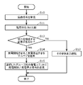
- FIG. 3 is a flowchart showing the basic processing procedure of the control device 20 in the power generation system 10 (that is, the control method of the power generation system 10).
- the control device 20 receives a load signal indicating the power to be supplied from the load to which the power generation system 10 supplies power (hereinafter, this power is also referred to as "required power") to the load through power line communication or the like via the power system. is received (S10).
- the control device 20 compares the requested power indicated by the received load signal with the current output power of the power generation system 10 (hereinafter this output power is also referred to as "current power") (S11).
- this output power is also referred to as "current power”
- the control device 20 controls the output power of the power generation unit group 15 and stores the current output power received from the power generation unit group 15 in the storage section 23, by referring to the storage section 23, The current output power of the power generation system 10 can be known.
- the control device 20 determines whether or not it is necessary to increase or decrease the output power based on the comparison result between the requested power and the current power (S12). Specifically, if the current power is within a certain range of the required power (for example, within ⁇ 5%), the control device 20 determines that there is no need to increase or decrease the output power (No in S12), and leaves the output power unchanged. Operation is continued with the output power (S13).
- the control device 20 determines that it is necessary to increase or decrease the output power (Yes in S12), and starts or starts power generation.
- a group to be stopped is selected (S14), and a signal to start or stop power generation is transmitted to the power generation units in the selected group via the communication device 22 (S15).
- the number of power generation units that start or stop generating power is adjusted appropriately according to the amount of increase or decrease in the output power required in the group that starts or stops power generation. be.
- the power generation unit starts or stops generating power according to the power demand from the load, so that the output power of the power generation system 10 follows the demand power.
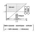
- FIG. 4 is a diagram showing an example of target values set for each group so that the lives of power generation units differ for each group.
- the horizontal axis indicates “maintenance timing”.
- the “maintenance time” is the time when the power generation unit reaches the end of its life, that is, the time when the power generation unit needs to be replaced because the degree of deterioration of the power generation unit reaches the upper limit.
- the vertical axis indicates "driving rate”.
- “Operating rate” is the operating rate of the power generation unit. For example, it is a parameter that correlates with the pace of increase in the cumulative power generation time. cumulative energization time ⁇ 100). The relationship between the "operating rate” and the "maintenance timing” is such that the product of them is constant.
- FIG. 4 shows an example in which the target values are set such that the actual operation rates of groups A, B, C, D, and E are 100%, 90%, 80%, 70%, and 60%, respectively. It is With such a setting, when the target operation is performed, the maintenance periods of groups A, B, C, D, and E are, for example, 8 years, 9 years, 10 years, 11 years, and 12 years, respectively. Become.
- the setting of the target value (here, the operating rate) is specifically realized by recording the target value in the storage unit 23 of the control device 20 .
- Such setting of the target value may be performed by manual input to the control device 20, or may be automatically performed by the control device 20 according to a predetermined program.
- the parameter to be used for deterioration control may be determined by manual input to the control device 20, or may be automatically performed by the control device 20 according to a predetermined program.
- Control example 1 As control example 1, ⁇ 1 (actual operating rate/target operating rate ) will be described in detail when the control device 20 performs deterioration control.
- FIG. 5 is a diagram for explaining the control algorithm of Control Example 1.
- the horizontal axis is ⁇ 1 (that is, an example of the first ratio).
- ⁇ 1 actual operating rate/target operating rate.
- the actual operation rate cumulative power generation time / period of use.
- the target operating rate is a target value for the operating rate.
- the vertical axis is ⁇ 2 in FIG. 8, which will be described later, it is ignored in the explanation of Control Example 1.
- ⁇ 1 has the following characteristics. In other words, as indicated by “during stop” in FIG. 5, when the power generation unit stops generating power, ⁇ 1 depends on the actual operation rate and thus decreases. On the other hand, when the power generation unit is generating power, as shown in FIG. 5, ⁇ 1 increases because it depends on the actual operation rate. Based on such characteristics of ⁇ 1, the following control is performed in Control Example 1.
- the group with the smaller ⁇ 1 is preferentially selected from among the groups in which power generation is stopped, and power generation is started. By doing so, ⁇ 1 of that group is controlled to approach 1.0.
- stop sorting ⁇ 1 when the output power of the power generation system 10 is reduced, the group with a large ⁇ 1 is preferentially selected among the groups that are generating power, and power generation is stopped. Thus, ⁇ 1 of that group is controlled to approach 1.0.
- deterioration control is performed by using ⁇ 1 (that is, an example of the first ratio) as a parameter for selecting a group for starting or stopping power generation.
- FIG. 6 is a flowchart showing the processing procedure of Control Example 1.
- FIG. This processing procedure corresponds to a specific example of steps S12 to S15 in FIG.
- the target operation rates of groups A, B, C, D, and E are, for example, 100%, 90%, 80%, 70%, and 60%, respectively, as shown in FIG. is set to
- control device 20 compares the requested power with the current power to determine whether or not to increase or decrease the group that generates power (S20).
- the control device 20 preferentially selects groups with a large ⁇ 1 among the groups that are generating power, and selects the required number of groups. is selected, and the power generation units of the selected group are stopped (S22).
- the order of stopping power generation for each group is arbitrary. For example, power generation may be stopped in the selected order, power generation may be stopped regardless of the selected order, or power generation may be started simultaneously in all selected groups.
- "to stop power generation” includes stopping power generation by a power generating unit that is generating power and stopping power generation by a power generating unit that is in a standby state.
- FIG. 7 is a diagram showing a time-series example of group selection in Control Example 1.
- FIG. The upper part of FIG. 7 shows an example of changes over time and the output power of the power generation system 10, and the lower part of FIG. ” ( ⁇ means operation, ⁇ means stop).
- the control device 20 which has received the required power of 30 kw, determines that the number of groups that generate power will be reduced ("Yes (decrease)" in S20 of FIG. 6). , groups with a large ratio ( ⁇ 1) (here, group E with a ratio ( ⁇ 1) of 1.5 and group B with a ratio ( ⁇ 1) of 1.2) are preferentially selected, and the selected groups Power generation units E and B are stopped (S22 in FIG. 6). In addition, in this control example 1, the power generated by one group is 10 kw.
- the control device 20 which has received the requested power of 40 kw, determines to increase the number of groups that generate power (“Yes (increase)” in S20 of FIG. 6), so group B that has stopped power generation and E, a group with a small ratio ( ⁇ 1) (here, group B with a ratio ( ⁇ 1) of 1.1) is preferentially selected, and the power generation units of the selected group B are started to generate power (FIG. 6 of S21).
- the power generation start/stop of the power generation units is controlled so that the ratio ( ⁇ 1) of each of the groups A to D approaches 1.0 every certain period of time ⁇ t.
- the maintenance periods of Groups A, B, C, D and E which were set to 100%, 90%, 80%, 70% and 60% as target operation rates, respectively, were 8 years, 9 years and 10 years. Years, 11 years, 12 years approaching. This prevents two or more groups from reaching the maintenance timing at the same time, and there is a problem that many power generation units need to be replaced at the same time. The problem of lowering is suppressed.
- the target operation rate of each group may be updated as the usage period of the power generation unit elapses.
- ⁇ 1 (that is, an example of the first ratio) was used as a parameter for selecting a group for starting or stopping power generation. may also be used when determining which power generation unit is to start or stop power generation.
- Control example 2 As control example 2, ⁇ 2 (actual operation frequency/target operation frequency), which is an example of the ratio of a parameter correlated to the pace of increase in the number of times of power generation to the target value of the parameter (this ratio is also referred to as a “second ratio”). will be described in detail when the control device 20 performs deterioration control using .
- “Operating frequency” is the power generation frequency of the power generation unit, and is, for example, a parameter that correlates with the pace of increase in the number of times of power generation.
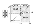
- FIG. 8 is a diagram for explaining the control algorithm of Control Example 2.
- the vertical axis is ⁇ 2 (that is, an example of the second ratio).
- ⁇ 2 actual operating frequency ⁇ target operating frequency.
- actual operation frequency number of times of power generation / period of use.
- the target operating frequency is a target value for operating frequency.
- the horizontal axis is ⁇ 1 in FIG. 5, it is ignored in the explanation of this control example 2.
- ⁇ 2 has the following characteristics. That is, as indicated by “during stop” in FIG. 8, when the power generation unit stops generating power, ⁇ 2 decreases because it depends on the actual frequency of operation. Similarly, when the power generating unit is generating power, as indicated by “generating” in FIG. 8, ⁇ 2 also decreases because it depends on the actual operating frequency. Based on such characteristics of ⁇ 2, the control example 2 performs the following control.
- power generation sorting ⁇ 2 when increasing the output power of the power generation system 10, the group with the smaller ⁇ 2 is preferentially selected from among the groups in which power generation is stopped, and power generation is started. By doing so, ⁇ 2 of that group is controlled to approach 1.0.
- stop sorting ⁇ 2 when the output power of the power generation system 10 is reduced, the group with a smaller ⁇ 2 is preferentially selected among the groups that are generating power, and power generation is stopped. By doing so, ⁇ 2 of that group is controlled to approach 1.0.
- deterioration control is performed by using ⁇ 2 (that is, an example of the second ratio) as a parameter for selecting a group for starting or stopping power generation.
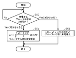
- FIG. 9 is a flowchart showing the processing procedure of Control Example 2.
- This processing procedure corresponds to a specific example of steps S12 to S15 in FIG.
- the target operation frequency is set so that the maintenance timings of groups A, B, C, D, and E are, for example, 8 years, 9 years, 10 years, 11 years, and 12 years. is set.
- control device 20 compares the requested power with the current power to determine whether or not to increase or decrease the group that generates power (S30).
- the control device 20 preferentially selects groups with small ⁇ 2 among the groups that are generating power. is selected, and the power generation units of the selected group are stopped (S32).
- FIG. 10 is a diagram showing a time-series example of group selection in Control Example 2.
- FIG. The upper part of FIG. 10 shows an example of changes in the output power of the power generation system 10 over time, and the lower part of FIG. ” ( ⁇ means operation, ⁇ means stop).
- . . , t9 is .DELTA.t (not shown) as in control example 1 shown in FIG.
- the control device 20 determines to increase the number of groups that generate power ("Yes (increase)" in S30 of FIG. 9), so that the groups B to E that have stopped generating power group with a small ratio ( ⁇ 2) (here, group B with a ratio ( ⁇ 2) of 0.87, group C with a ratio ( ⁇ 2) of 0.95, and group C with a ratio ( ⁇ 2) of 1.06 Group D) is preferentially selected, and the power generation units of the selected groups B to D are started to generate power (S31 in FIG. 9).
- the power generated by one group is 10 kw. Therefore, at this time t1, three groups are selected to increase the output power by 30 kw.
- the order in which the selected groups B to D start generating power is arbitrary. For example, power generation may be started in the selected order, power generation may be started regardless of the selected order, or the selected groups B to D may be simultaneously started to generate power.
- the control device 20 determines to reduce the group that generates power ("Yes (decrease)" in S30 of FIG. 9), so among the groups A to D during power generation, , a group with a small ratio ( ⁇ 2) (here, group A with a ratio ( ⁇ 2) of 0.91 and group B with a ratio ( ⁇ 2) of 0.99) are preferentially selected, and the selected group Power generation units A and B are stopped (S32 in FIG. 9).
- ⁇ 2 group with a small ratio
- the selected group Power generation units A and B are stopped (S32 in FIG. 9).
- two groups are selected to reduce the output power of 20 kw.
- the order in which the selected groups A and B are stopped to generate power is arbitrary. For example, power generation may be stopped in the selected order, power generation may be stopped regardless of the selected order, or the selected groups A and B may be stopped at the same time.
- the power generation start/stop of the power generation units is controlled so that the ratio ( ⁇ 2) of each of the groups A to D approaches 1.0 at regular intervals ⁇ t.
- the maintenance periods of groups A, B, C, D, and E which were set to have maintenance periods of 8 years, 9 years, 10 years, 11 years, and 12 years as the target operation frequency, were set to 8 years, respectively. 2019, 9th, 10th, 11th, 12th. This prevents two or more groups from reaching the maintenance timing at the same time, and there is a problem that many power generation units need to be replaced at the same time. The problem of lowering is suppressed.
- the target operation frequency of each group may be updated as the usage period of the power generation unit elapses.
- ⁇ 2 (that is, an example of the second ratio) was used as a parameter for selecting a group for starting or stopping power generation. may also be used when determining which power generation unit is to start or stop power generation.
- Control example 3 As control example 3, both ⁇ 1 used in control example 1 (ie, an example of the first ratio) and ⁇ 2 used in control example 2 (ie, an example of the second ratio) are used to degrade the control device 20. The details of the control will be explained.
- FIG. 11 is a diagram for explaining the control algorithm of Control Example 3.
- the horizontal axis is ⁇ 1.
- the vertical axis is ⁇ 2.
- ⁇ 1 and ⁇ 2 have the following characteristics. In other words, when the power generation unit stops generating power, as indicated by the two “during suspension” in FIG. It becomes smaller because it depends on the operation frequency of On the other hand, when the power generation unit is generating power, as shown by the two "generating” in FIG. It becomes smaller because it depends on the driving frequency. Based on such characteristics of ⁇ 1 and ⁇ 2, in Control Example 3, the following control is performed.
- power generation sorting ⁇ 2 when increasing the output power of the power generation system 10, a group with a small ⁇ 2 is preferentially selected from among the groups in which power generation is stopped, and power generation is started. By doing so, ⁇ 2 of that group is controlled to approach 1.0.
- stop sorting ⁇ 1 when the output power of the power generation system 10 is reduced, the group with a large ⁇ 1 is preferentially selected among the groups that are generating power, and power generation is stopped. Thus, ⁇ 1 of that group is controlled to approach 1.0.
- ⁇ 1 that is, an example of the first ratio
- ⁇ 2 that is, an example of the second ratio
- FIG. 12 is a flowchart showing the processing procedure of Control Example 3.
- This processing procedure corresponds to a specific example of steps S12 to S15 in FIG.
- the target operation rates of groups A, B, C, D, and E are, for example, 100%, 90%, 80%, 70%, and 60%, respectively, as shown in FIG. and the target operation frequency is set such that the maintenance timings of groups A, B, C, D, and E are, for example, 8 years, 9 years, 10 years, 11 years, and 12 years, respectively. ing.
- control device 20 compares the requested power with the current power to determine whether or not to increase or decrease the group that generates power (S40).
- the control device 20 preferentially selects groups with large ⁇ 1 among the groups that are generating power, and selects the required number of groups. is selected, and the power generation units of the selected group are stopped (S42).
- the order of stopping power generation for each group is arbitrary. For example, power generation may be stopped in the selected order, power generation may be started regardless of the selected order, or power generation may be stopped simultaneously for all selected groups.
- Control Example 3 the power generation start/stop of the power generation unit is controlled so that ⁇ 1 and ⁇ 2 approach 1.0.
- the target operating rates are set to 100%, 90%, 80%, 70%, and 60%, respectively, and the target operating frequencies are set to maintenance periods of 8, 9, 10, 11, and 12 years, respectively.
- the maintenance timings of groups A, B, C, D, and E which are set as follows, approach 8 years, 9 years, 10 years, 11 years, and 12 years, respectively. This prevents two or more groups from reaching the maintenance timing at the same time, and there is a problem that many power generation units need to be replaced at the same time. The problem of lowering is suppressed.
- ⁇ 1 that is, an example of the first ratio
- ⁇ 2 that is, an example of the second ratio
- Control example 4 In Control Example 4, as in Control Example 3, both ⁇ 1 used in Control Example 1 (that is, an example of the first ratio) and ⁇ 2 used in Control Example 2 (that is, an example of the second ratio) are Although the control device 20 performs deterioration control using the control device 20, the specific control contents are different from those of the control example 3.
- FIG. 13 is a diagram for explaining the control algorithm of Control Example 4.
- the horizontal axis is ⁇ 1.
- the vertical axis is ⁇ 2.
- control example 4 when increasing the output power of the power generation system 10, the group with a small ⁇ 3 is preferentially selected from among the groups in which power generation is stopped.
- ⁇ 3 of the group is controlled to approach 1.0.
- FIG. 14 is a flowchart showing the processing procedure of Control Example 4.
- This processing procedure corresponds to a specific example of steps S12 to S15 in FIG.
- the target operation rates of groups A, B, C, D, and E are, for example, 100%, 90%, 80%, 70%, and 60%, respectively, as shown in FIG. and the target operation frequency is set such that the maintenance timings of groups A, B, C, D, and E are, for example, 8 years, 9 years, 10 years, 11 years, and 12 years, respectively. ing.
- control device 20 compares the requested power with the current power to determine whether or not to increase or decrease the group that generates power (S50).
- the control device 20 preferentially selects groups with large ⁇ 4 among the groups that are generating power, and selects the required number of groups. is selected, and the power generation units of the selected group are stopped (S52).
- the order of stopping power generation for each group is arbitrary. For example, power generation may be stopped in the selected order, power generation may be started regardless of the selected order, or power generation may be stopped simultaneously for all selected groups.
- Control Example 4 the power generation start/stop of the power generation unit is controlled so that ⁇ 3 and ⁇ 4 approach 1.0.
- the target operating rates are set to 100%, 90%, 80%, 70%, and 60%, respectively, and the target operating frequencies are set to maintenance periods of 8, 9, 10, 11, and 12 years, respectively.
- the maintenance timings of groups A, B, C, D, and E which are set as follows, approach 8 years, 9 years, 10 years, 11 years, and 12 years, respectively. This prevents two or more groups from reaching the maintenance timing at the same time, and there is a problem that many power generation units need to be replaced at the same time. The problem of lowering is suppressed.
- ⁇ 3 and ⁇ 4 are used as parameters for selecting a group for starting or stopping power generation. It may also be used in determining the power generation unit.
- the power generation unit group 15 which is a collection of power generation units including fuel cells
- the power generation unit group 15 is divided into a plurality of groups. and control the generation units to degrade to different degrees for each group.
- Such deterioration control prevents two or more groups of power generation units from reaching maintenance timing at the same time, and the power generation system 10 including a plurality of power generation units can be stably operated for a long period of time.
- the degree of deterioration corresponds to a parameter that indicates the amount of operation of the power generation unit, and when the parameter reaches the upper limit value, the power generation unit is controlled so as not to start again. This ensures time to replace the power generation unit when the power generation unit reaches the end of its life.
- the parameters may include parameters that correlate with the cumulative power generation time of the power generation unit.
- the power generation units are controlled to deteriorate at different degrees for each group based on the parameter correlated with the cumulative power generation time.
- the groups to start power generation are selected in ascending order of the first ratio of the parameter correlated to the pace of increase in the cumulative power generation time to the target value of the parameter. Then, when reducing the groups for which power generation is to be performed, the groups for which power generation is to be stopped are selected in descending order of the first ratio of the parameter correlated to the pace of increase in the cumulative power generation time to the target value of the parameter.
- the groups for which power generation is to be stopped are selected in descending order of the first ratio of the parameter correlated to the pace of increase in the cumulative power generation time to the target value of the parameter.
- the parameters may also include parameters that correlate with the number of times the power generation unit generates power. As a result, based on the parameter correlated with the number of times of power generation, control is performed so that the power generation units are degraded to different degrees for each group.
- the groups that start generating power are selected in ascending order of the second ratio of the parameter correlated to the pace of increase in the number of times of power generation to the target value of the parameter. Then, when reducing the groups for which power generation is to be performed, the groups for which power generation is to be stopped are selected in ascending order of the second ratio of the parameter correlated to the pace of increase in the number of times of power generation to the target value of the parameter.
- the groups for which power generation is to be stopped are selected in ascending order of the second ratio of the parameter correlated to the pace of increase in the number of times of power generation to the target value of the parameter.
- the parameters may also include a parameter correlated with the cumulative power generation time of the power generation unit and a parameter correlated with the number of power generations of the power generation unit.
- the groups for which power generation is to be started are selected in ascending order of the second ratio of the parameter correlated to the pace of increase in the number of times of power generation to the target value of the parameter.
- the groups for which power generation is to be stopped may be selected in descending order of the first ratio of the parameter correlated to the pace of increase of the cumulative power generation time to the target value of the parameter.
- a first ratio of the parameter correlated to the pace of increase in the cumulative power generation time to the target value of the parameter and a second ratio of the parameter correlated to the pace of increase in the number of times of power generation to the target value of the parameter.
- the group to start power generation is selected in order of the smallest square root of the sum of the squares of the ratios of .
- the second ratio of the parameter correlated to the increase pace of the number of times of power generation to the target value of the parameter is the first ratio of the parameter correlated to the target value of the parameter correlated to the increase pace of the cumulative power generation time.
- the group whose power generation is to be stopped is selected in descending order of the ratio of .
- control device 20 in the power generation system 10 includes a communication device 22 as a receiver for receiving information indicating the degree of deterioration from each of the power generation units constituting the power generation unit group 15, and a power generation unit
- the group 15 is divided into a plurality of groups, and a controller 21 is provided for performing control such that each group is degraded to a different degree. This prevents two or more groups from reaching maintenance timing at the same time, and the power generation system 10 including a plurality of power generation units can be stably operated for a long period of time.
- the power generation system 10 includes the power generation unit groups 15, and the control device 20 that divides the power generation unit groups 15 into a plurality of groups and controls the power generation units to deteriorate at different degrees for each group. Prepare. This prevents two or more groups from reaching maintenance timing at the same time, and the power generation system 10 including a plurality of power generation units can be stably operated for a long period of time.
- control method the control device, and the power generation system of the power generation system according to the present disclosure have been described above based on the embodiments, the present disclosure is not limited to these embodiments. As long as it does not depart from the gist of the present disclosure, various modifications that a person skilled in the art can think of are applied to the present embodiment, and another form constructed by combining some components in the embodiment is also within the scope of the present disclosure. contained within.
- the power generation system 10 has one control device 20, but it may be distributed to a plurality of control devices. In other words, deterioration control may be performed by coordinated control by a plurality of distributed control devices.
- a distributed controller or an integrated controller may be a stand-alone device or a device integrated into a power generation unit.
- control device 20 sets the target value for each group so that the maintenance time for each group is different after considering the life that has already passed for each group, and performs deterioration control. conduct.
- the present disclosure can be used as a power generation system or the like that includes a plurality of power generation units including fuel cells, particularly as a power generation system or the like that enables stable operation over a long period of time.
- power generation system 15 power generation unit group 20, 30 control device 21, 31 controller 22, 32 communication device 23, 33 storage unit 34 power conditioner 35 fuel cell stack a1 to an, b1 to bn, c1 to cn, d1 to dn , e1 ⁇ en generation unit
Landscapes
- Engineering & Computer Science (AREA)
- Life Sciences & Earth Sciences (AREA)
- Manufacturing & Machinery (AREA)
- Sustainable Development (AREA)
- Sustainable Energy (AREA)
- Chemical & Material Sciences (AREA)
- Chemical Kinetics & Catalysis (AREA)
- Electrochemistry (AREA)
- General Chemical & Material Sciences (AREA)
- Power Engineering (AREA)
- Fuel Cell (AREA)
Abstract
Description
特許文献1の技術では、複数の発電ユニットが同時期に寿命を迎えることになってしまうことが考慮されていない。そのために、複数の発電ユニットが同時期に寿命を迎えたときには、多くの発電ユニットを同時期に交換する必要が生じる。また、発電ユニットの交換時に大きく発電出力が低下してしまうという問題も生じる。その結果、特許文献1の技術では、長期に安定して運転することが困難である。 (Findings on which this disclosure is based)
The technique of Patent Literature 1 does not consider that a plurality of power generation units will reach the end of their lives at the same time. Therefore, when a plurality of power generation units reach the end of their lives at the same time, many power generation units need to be replaced at the same time. In addition, there is also the problem that the power generation output drops significantly when the power generation unit is replaced. As a result, it is difficult for the technology of Patent Document 1 to operate stably for a long period of time.
以下、本開示の実施の形態について、図面を用いて詳細に説明する。なお、以下で説明する実施の形態は、いずれも本開示の一具体例を示す。以下の実施の形態で示される数値、形状、材料、構成要素、構成要素の配置位置及び接続形態、ステップ、ステップの順序等は、一例であり、本開示を限定する主旨ではない。また、各図は、必ずしも厳密に図示したものではない。各図において、実質的に同一の構成については同一の符号を付し、重複する説明は省略または簡略化する。 (Embodiment)
Hereinafter, embodiments of the present disclosure will be described in detail with reference to the drawings. It should be noted that each of the embodiments described below is a specific example of the present disclosure. Numerical values, shapes, materials, components, arrangement positions and connection forms of components, steps, order of steps, and the like shown in the following embodiments are examples, and are not intended to limit the present disclosure. Also, each figure is not necessarily strictly illustrated. In each figure, substantially the same configurations are denoted by the same reference numerals, and overlapping descriptions are omitted or simplified.
制御例1として、累積発電時間の増加ペースに相関するパラメータの当該パラメータの目標値に対する比(この比を「第1の比」ともいう)の一例であるγ1(実際の運転率/目標運転率)を用いて制御装置20が劣化制御を行う場合の詳細を説明する。 (Control example 1)
As control example 1, γ1 (actual operating rate/target operating rate ) will be described in detail when the
制御例2として、発電回数の増加ペースに相関するパラメータの当該パラメータの目標値に対する比(この比を「第2の比」ともいう)の一例であるγ2(実際の運転頻度/目標運転頻度)を用いて制御装置20が劣化制御を行う場合の詳細を説明する。「運転頻度」は、発電ユニットの発電頻度であり、例えば、発電回数の増加ペースに相関するパラメータであり、具体的には、使用期間に対する発電回数(つまり、発電回数÷使用期間)である。 (Control example 2)
As control example 2, γ2 (actual operation frequency/target operation frequency), which is an example of the ratio of a parameter correlated to the pace of increase in the number of times of power generation to the target value of the parameter (this ratio is also referred to as a “second ratio”). will be described in detail when the
制御例3として、制御例1で用いたγ1(つまり、第1の比の一例)及び制御例2で用いたγ2(つまり、第2の比の一例)の両方を用いて制御装置20が劣化制御を行う場合の詳細を説明する。 (Control example 3)
As control example 3, both γ1 used in control example 1 (ie, an example of the first ratio) and γ2 used in control example 2 (ie, an example of the second ratio) are used to degrade the
制御例4では、制御例3と同様に、制御例1で用いたγ1(つまり、第1の比の一例)及び制御例2で用いたγ2(つまり、第2の比の一例)の両方を用いて制御装置20が劣化制御を行うが、具体的な制御内容が制御例3と異なる。 (Control example 4)
In Control Example 4, as in Control Example 3, both γ1 used in Control Example 1 (that is, an example of the first ratio) and γ2 used in Control Example 2 (that is, an example of the second ratio) are Although the
15 発電ユニット群
20、30 制御装置
21、31 制御器
22、32 通信器
23、33 記憶部
34 パワーコンディショナ
35 燃料電池スタック
a1~an、b1~bn、c1~cn、d1~dn、e1~en 発電ユニット 10
Claims (16)
- 燃料電池を含む、複数の発電ユニットを備える発電システムにおいて、前記複数の発電ユニットを、複数のグループに分け、かつ前記グループ毎に異なる度合いで前記発電ユニットが劣化するよう制御する、発電システムの制御方法。 In a power generation system including a plurality of power generation units including a fuel cell, control of the power generation system by dividing the plurality of power generation units into a plurality of groups and controlling the power generation units to deteriorate to a different degree for each group. Method.
- 所定のグループの前記発電ユニットの劣化の度合いが上限に達して前記発電ユニットを交換しているときに、他のグループの前記発電ユニットの劣化の度合いが上限に達することのないようグループ毎に前記発電ユニットの劣化の度合いに差が設けられている、請求項1記載の発電システムの制御方法。 When the degree of deterioration of the power generation units of a predetermined group reaches the upper limit and the power generation units are being replaced, the degree of deterioration of the power generation units of other groups does not reach the upper limit. 2. The method of controlling a power generation system according to claim 1, wherein a difference is provided in the degree of deterioration of the power generation unit.
- 前記劣化の度合いは、前記発電ユニットの運転量を示すパラメータに対応し、前記パラメータが上限値に達すると前記発電ユニットに次の起動をさせないように制御する、請求項1記載の発電システムの制御方法。 2. The control of the power generation system according to claim 1, wherein said degree of deterioration corresponds to a parameter indicating the amount of operation of said power generation unit, and when said parameter reaches an upper limit value, said power generation unit is controlled not to start next time. Method.
- 前記パラメータは、前記発電ユニットの累積発電時間に相関するパラメータを含む、請求項3記載の発電システムの制御方法。 The method of controlling a power generation system according to claim 3, wherein said parameters include parameters correlated with cumulative power generation time of said power generation unit.
- 発電する前記グループを増加させるとき、前記累積発電時間の増加ペースに相関するパラメータの当該パラメータの目標値に対する第1の比が小さい順に発電開始させる前記グループを選択する、請求項4に記載の発電システムの制御方法。 5. The power generation according to claim 4, wherein when increasing the groups for which power generation is to be performed, the groups for which power generation is to be started are selected in ascending order of a first ratio of a parameter correlated to an increase pace of the cumulative power generation time to a target value of the parameter. How the system is controlled.
- 発電する前記グループを減少させるとき、前記累積発電時間の増加ペースに相関するパラメータの当該パラメータの目標値に対する第1の比が大きい順に発電停止させる前記グループを選択する、請求項4または5に記載の発電システムの制御方法。 6. The group according to claim 4 or 5, wherein when the groups that generate power are reduced, the groups for which power generation is stopped are selected in descending order of a first ratio of a parameter correlated to an increase pace of the cumulative power generation time to a target value of the parameter. power generation system control method.
- 前記パラメータは、前記発電ユニットの発電回数に相関するパラメータを含む、請求項3記載の発電システムの制御方法。 The control method of the power generation system according to claim 3, wherein the parameters include parameters that correlate with the number of power generation times of the power generation unit.
- 発電する前記グループを増加させるとき、前記発電回数の増加ペースに相関するパラメータの当該パラメータの目標値に対する第2の比が小さい順に発電開始させる前記グループを選択する、請求項7に記載の発電システムの制御方法。 8. The power generation system according to claim 7, wherein when increasing the number of groups for which power generation is to be performed, the groups for which power generation is started are selected in ascending order of a second ratio of a parameter correlated to the pace of increase in the number of times of power generation to a target value of the parameter. control method.
- 発電する前記グループを減少させるとき、前記発電回数の増加ペースに相関するパラメータの当該パラメータの目標値に対する第2の比が小さい順に発電停止させる前記グループを選択する、請求項7に記載の発電システムの制御方法。 8. The power generation system according to claim 7, wherein when the groups that generate power are reduced, the groups for which power generation is stopped are selected in ascending order of a second ratio of a parameter correlated to the pace of increase in the number of times of power generation to a target value of the parameter. control method.
- 前記パラメータは、前記発電ユニットの累積発電時間に相関するパラメータ、及び前記発電ユニットの発電回数に相関するパラメータを含む、請求項3記載の発電システムの制御方法。 The power generation system control method according to claim 3, wherein the parameters include a parameter correlated with the cumulative power generation time of the power generation unit and a parameter correlated with the number of power generation times of the power generation unit.
- 発電する前記グループを増加させるとき、前記発電回数の増加ペースに相関するパラメータの当該パラメータの目標値に対する第2の比が小さい順に発電開始させる前記グループを選択する、請求項10に記載の発電システムの制御方法。 11. The power generation system according to claim 10, wherein when increasing the groups that generate power, the groups that start generating power are selected in ascending order of a second ratio of a parameter correlated to the pace of increase in the number of times of power generation to a target value of the parameter. control method.
- 発電する前記グループを減少させるとき、前記累積発電時間の増加ペースに相関するパラメータの当該パラメータの目標値に対する第1の比が大きい順に発電停止させる前記グループを選択する、請求項10または11に記載の発電システムの制御方法。 12. The group according to claim 10, wherein when the groups that generate power are reduced, the groups for which power generation is stopped are selected in descending order of a first ratio of a parameter correlated to an increase pace of the cumulative power generation time to a target value of the parameter. power generation system control method.
- 発電する前記グループを増加させるとき、前記累積発電時間の増加ペースに相関するパラメータの当該パラメータの目標値に対する第1の比と前記発電回数の増加ペースに相関するパラメータの当該パラメータの目標値に対する第2の比の二乗和平方根が小さい順に発電開始させる前記グループを選択する、請求項10に記載の発電システムの制御方法。 When increasing the number of groups that generate power, a first ratio of a parameter correlated to the pace of increase in the cumulative power generation time to a target value of the parameter and a ratio of a parameter correlated to the pace of increase in the number of times of power generation to the target value of the parameter. 11. The method of controlling a power generation system according to claim 10, wherein the groups for starting power generation are selected in ascending order of the square root of the sum of squares of the ratio of 2.
- 発電する前記グループを減少させるとき、前記発電回数の増加ペースに相関するパラメータの当該パラメータの目標値に対する第2の比に対する前記累積発電時間の増加ペースに相関するパラメータの当該パラメータの目標値に対する第1の比の比が大きい順に発電停止させる前記グループを選択する、請求項10に記載の発電システムの制御方法。 When the group that generates power is reduced, a second ratio of the parameter correlated to the increase pace of the number of times of power generation to the target value of the parameter correlates to the target value of the parameter correlated to the increase pace of the cumulative power generation time. 11. The method of controlling a power generation system according to claim 10, wherein said groups for which power generation is to be stopped are selected in descending order of the ratio of 1.
- 燃料電池を含む、複数の発電ユニットの夫々から、劣化の度合いを示す情報を受信する受信器と、
前記複数の発電ユニットを、複数のグループに分け、かつ前記グループ毎に異なる度合いで前記発電ユニットが劣化するよう制御する制御器とを備える、制御装置。 a receiver that receives information indicating the degree of deterioration from each of a plurality of power generation units, including fuel cells;
and a controller that divides the plurality of power generation units into a plurality of groups and controls the power generation units to deteriorate to a different degree for each group. - 燃料電池を含む、複数の発電ユニットと、
請求項15記載の制御装置とを備える、発電システム。 a plurality of power generation units including fuel cells;
A power generation system comprising the control device according to claim 15 .
Priority Applications (4)
| Application Number | Priority Date | Filing Date | Title |
|---|---|---|---|
| JP2023510784A JPWO2022209687A1 (en) | 2021-03-31 | 2022-03-10 | |
| EP22779910.3A EP4318692A1 (en) | 2021-03-31 | 2022-03-10 | Power generation system control method, control device, and power generation system |
| CN202280024894.0A CN117099232A (en) | 2021-03-31 | 2022-03-10 | Control method and control device for power generation system and power generation system |
| US18/458,194 US20230411657A1 (en) | 2021-03-31 | 2023-08-30 | Method for controlling power generation system, control apparatus, and power generation system |
Applications Claiming Priority (4)
| Application Number | Priority Date | Filing Date | Title |
|---|---|---|---|
| JP2021-061576 | 2021-03-31 | ||
| JP2021061576 | 2021-03-31 | ||
| JP2022022508 | 2022-02-16 | ||
| JP2022-022508 | 2022-02-16 |
Related Child Applications (1)
| Application Number | Title | Priority Date | Filing Date |
|---|---|---|---|
| US18/458,194 Continuation US20230411657A1 (en) | 2021-03-31 | 2023-08-30 | Method for controlling power generation system, control apparatus, and power generation system |
Publications (1)
| Publication Number | Publication Date |
|---|---|
| WO2022209687A1 true WO2022209687A1 (en) | 2022-10-06 |
Family
ID=83455914
Family Applications (1)
| Application Number | Title | Priority Date | Filing Date |
|---|---|---|---|
| PCT/JP2022/010448 WO2022209687A1 (en) | 2021-03-31 | 2022-03-10 | Power generation system control method, control device, and power generation system |
Country Status (4)
| Country | Link |
|---|---|
| US (1) | US20230411657A1 (en) |
| EP (1) | EP4318692A1 (en) |
| JP (1) | JPWO2022209687A1 (en) |
| WO (1) | WO2022209687A1 (en) |
Citations (3)
| Publication number | Priority date | Publication date | Assignee | Title |
|---|---|---|---|---|
| JPH0750172A (en) * | 1993-08-04 | 1995-02-21 | Yoyu Tansanengata Nenryo Denchi Hatsuden Syst Gijutsu Kenkyu Kumiai | Fuel cell power generating plant and method and device for controlling operation thereof |
| JP2007122930A (en) * | 2005-10-25 | 2007-05-17 | Kawamura Electric Inc | Fuel cell unit |
| JP5248711B2 (en) | 2010-07-07 | 2013-07-31 | パナソニック株式会社 | Fuel cell system and operation method thereof |
-
2022
- 2022-03-10 JP JP2023510784A patent/JPWO2022209687A1/ja active Pending
- 2022-03-10 WO PCT/JP2022/010448 patent/WO2022209687A1/en active Application Filing
- 2022-03-10 EP EP22779910.3A patent/EP4318692A1/en active Pending
-
2023
- 2023-08-30 US US18/458,194 patent/US20230411657A1/en active Pending
Patent Citations (3)
| Publication number | Priority date | Publication date | Assignee | Title |
|---|---|---|---|---|
| JPH0750172A (en) * | 1993-08-04 | 1995-02-21 | Yoyu Tansanengata Nenryo Denchi Hatsuden Syst Gijutsu Kenkyu Kumiai | Fuel cell power generating plant and method and device for controlling operation thereof |
| JP2007122930A (en) * | 2005-10-25 | 2007-05-17 | Kawamura Electric Inc | Fuel cell unit |
| JP5248711B2 (en) | 2010-07-07 | 2013-07-31 | パナソニック株式会社 | Fuel cell system and operation method thereof |
Also Published As
| Publication number | Publication date |
|---|---|
| US20230411657A1 (en) | 2023-12-21 |
| EP4318692A1 (en) | 2024-02-07 |
| JPWO2022209687A1 (en) | 2022-10-06 |
Similar Documents
| Publication | Publication Date | Title |
|---|---|---|
| JP6897250B2 (en) | Electrolysis system, electrolysis control device and control method of electrolysis system | |
| JP5924524B2 (en) | Storage battery control device, storage battery control method, program, power storage system, and power supply system | |
| JP6238107B2 (en) | Storage battery management system | |
| JP6919506B2 (en) | Electrolysis system, electrolysis control device and control method of electrolysis system | |
| US9496725B2 (en) | Power control apparatus, method, program, and integrated circuit, and storage battery unit | |
| JP5809329B2 (en) | Power conversion system | |
| US9575501B2 (en) | Method of controlling frequency, frequency control system, frequency control apparatus, and program | |
| WO2013128985A1 (en) | Battery control device, battery control method, program, power storage system and power supply system | |
| CN105723588A (en) | Uninterruptible power supply control | |
| US11121554B2 (en) | Electrical power control apparatus, electrical power control method and electrical power control system | |
| EP3334001B1 (en) | Reactive power compensation apparatus and control method thereof | |
| JPWO2013145263A1 (en) | Power converter | |
| WO2022209687A1 (en) | Power generation system control method, control device, and power generation system | |
| JP2017139834A (en) | Power conversion device and power conditioner system | |
| KR101020200B1 (en) | Power controlling method of Fuel cell and Fuel cell system | |
| US20160359327A1 (en) | Microgrid system and control method for the same | |
| WO2011055184A1 (en) | Power supply device and controller used therefor | |
| CN117099232A (en) | Control method and control device for power generation system and power generation system | |
| EP3567691B1 (en) | Composite power storage system and power storage method | |
| JP2016073128A (en) | Power conversion device, power distribution control device, and control method | |
| WO2017131094A1 (en) | Power generation system, method for controlling power generation system, and power generation device | |
| JP2001190026A (en) | Apparatus and method for operation of system link inverter and recording medium, in which program for operation of system link inverter is recorded and, which can be read by computer | |
| JP2018036827A (en) | Solar power generation power converter, control method, and solar power generation system | |
| JP6229777B1 (en) | Electric power leveling device | |
| JP2016100950A (en) | Charge/discharge control device and battery system including the same |
Legal Events
| Date | Code | Title | Description |
|---|---|---|---|
| 121 | Ep: the epo has been informed by wipo that ep was designated in this application |
Ref document number: 22779910 Country of ref document: EP Kind code of ref document: A1 |
|
| WWE | Wipo information: entry into national phase |
Ref document number: 2023510784 Country of ref document: JP |
|
| WWE | Wipo information: entry into national phase |
Ref document number: 202280024894.0 Country of ref document: CN |
|
| WWE | Wipo information: entry into national phase |
Ref document number: 2022779910 Country of ref document: EP |
|
| ENP | Entry into the national phase |
Ref document number: 2022779910 Country of ref document: EP Effective date: 20231031 |
|
| NENP | Non-entry into the national phase |
Ref country code: DE |