WO2022209668A1 - 平面検出装置および平面検出方法 - Google Patents
平面検出装置および平面検出方法 Download PDFInfo
- Publication number
- WO2022209668A1 WO2022209668A1 PCT/JP2022/010326 JP2022010326W WO2022209668A1 WO 2022209668 A1 WO2022209668 A1 WO 2022209668A1 JP 2022010326 W JP2022010326 W JP 2022010326W WO 2022209668 A1 WO2022209668 A1 WO 2022209668A1
- Authority
- WO
- WIPO (PCT)
- Prior art keywords
- plane
- likelihood
- visible image
- image information
- sample points
- Prior art date
- Legal status (The legal status is an assumption and is not a legal conclusion. Google has not performed a legal analysis and makes no representation as to the accuracy of the status listed.)
- Ceased
Links
Images







Classifications
-
- G—PHYSICS
- G06—COMPUTING OR CALCULATING; COUNTING
- G06T—IMAGE DATA PROCESSING OR GENERATION, IN GENERAL
- G06T7/00—Image analysis
- G06T7/10—Segmentation; Edge detection
- G06T7/11—Region-based segmentation
-
- G—PHYSICS
- G06—COMPUTING OR CALCULATING; COUNTING
- G06T—IMAGE DATA PROCESSING OR GENERATION, IN GENERAL
- G06T7/00—Image analysis
- G06T7/60—Analysis of geometric attributes
-
- G—PHYSICS
- G01—MEASURING; TESTING
- G01B—MEASURING LENGTH, THICKNESS OR SIMILAR LINEAR DIMENSIONS; MEASURING ANGLES; MEASURING AREAS; MEASURING IRREGULARITIES OF SURFACES OR CONTOURS
- G01B11/00—Measuring arrangements characterised by the use of optical techniques
-
- G—PHYSICS
- G01—MEASURING; TESTING
- G01B—MEASURING LENGTH, THICKNESS OR SIMILAR LINEAR DIMENSIONS; MEASURING ANGLES; MEASURING AREAS; MEASURING IRREGULARITIES OF SURFACES OR CONTOURS
- G01B11/00—Measuring arrangements characterised by the use of optical techniques
- G01B11/24—Measuring arrangements characterised by the use of optical techniques for measuring contours or curvatures
-
- G—PHYSICS
- G06—COMPUTING OR CALCULATING; COUNTING
- G06T—IMAGE DATA PROCESSING OR GENERATION, IN GENERAL
- G06T7/00—Image analysis
- G06T7/10—Segmentation; Edge detection
- G06T7/143—Segmentation; Edge detection involving probabilistic approaches, e.g. Markov random field [MRF] modelling
-
- G—PHYSICS
- G06—COMPUTING OR CALCULATING; COUNTING
- G06T—IMAGE DATA PROCESSING OR GENERATION, IN GENERAL
- G06T7/00—Image analysis
- G06T7/50—Depth or shape recovery
-
- G—PHYSICS
- G06—COMPUTING OR CALCULATING; COUNTING
- G06T—IMAGE DATA PROCESSING OR GENERATION, IN GENERAL
- G06T7/00—Image analysis
- G06T7/70—Determining position or orientation of objects or cameras
-
- G—PHYSICS
- G06—COMPUTING OR CALCULATING; COUNTING
- G06T—IMAGE DATA PROCESSING OR GENERATION, IN GENERAL
- G06T2207/00—Indexing scheme for image analysis or image enhancement
- G06T2207/10—Image acquisition modality
- G06T2207/10024—Color image
-
- G—PHYSICS
- G06—COMPUTING OR CALCULATING; COUNTING
- G06T—IMAGE DATA PROCESSING OR GENERATION, IN GENERAL
- G06T2207/00—Indexing scheme for image analysis or image enhancement
- G06T2207/10—Image acquisition modality
- G06T2207/10028—Range image; Depth image; 3D point clouds
-
- G—PHYSICS
- G06—COMPUTING OR CALCULATING; COUNTING
- G06T—IMAGE DATA PROCESSING OR GENERATION, IN GENERAL
- G06T2207/00—Indexing scheme for image analysis or image enhancement
- G06T2207/20—Special algorithmic details
- G06T2207/20076—Probabilistic image processing
-
- G—PHYSICS
- G06—COMPUTING OR CALCULATING; COUNTING
- G06T—IMAGE DATA PROCESSING OR GENERATION, IN GENERAL
- G06T2207/00—Indexing scheme for image analysis or image enhancement
- G06T2207/20—Special algorithmic details
- G06T2207/20081—Training; Learning
Definitions
- the present disclosure relates to a plane detection device and a plane detection method.
- Patent Document 1 exists as a technique for detecting a plane.
- the technique disclosed in Patent Document 1 detects a plane from within an image captured by a TOF (Time Of Flight) camera.
- Patent Document 1 describes that plane information is detected by the RANSAC method from image data obtained by TOF.
- the present disclosure provides a plane detection device and a plane detection method that can detect the plane of an object with higher accuracy.
- a flat detection device includes: an information acquisition unit that acquires visible image information of an object having a predetermined plane and 3D coordinate information corresponding to the visible image information; a likelihood acquisition unit configured to acquire a likelihood indicating the flatness of the predetermined plane of the object from the visible image information; a plane detection unit that detects the predetermined plane of the object by a robust estimation method using the 3D coordinate information and the likelihood.
- a plane detection method includes: Acquiring visible image information of an object having a predetermined plane and 3D coordinate information corresponding to the visible image information, obtaining a likelihood indicating the planeness of the predetermined plane of the object from the visible image information; using the 3D coordinate information and the likelihood to detect the predetermined plane of the object by a robust estimation method.
- FIG. 1 is a diagram showing a schematic block configuration of a flatness detection device according to Embodiment 1 of the present disclosure
- FIG. FIG. 4 is a schematic diagram showing an exemplary palette included in the viewable image information
- FIG. 4 illustrates 3D coordinate information for an example palette
- FIG. 10 is a diagram illustrating likelihood for each pixel
- 4 is a flow chart showing the flow of a plane detection method
- It is a schematic diagram explaining the operation of the plane detection method.
- It is a schematic diagram explaining the operation of the plane detection method.
- It is a schematic diagram explaining the operation of the plane detection method.
- It is a schematic diagram explaining the operation of the plane detection method.
- It is a schematic diagram explaining the operation of the plane detection method.
- It is a schematic diagram explaining the operation of the plane detection method.
- 4 is a flowchart showing a specific flow of plane detection;
- FIG. 1 is a diagram showing a schematic block configuration of a flatness detection device according to Embodiment 1 of the
- 3 is a schematic diagram of an example palette; It is a schematic diagram explaining the operation of the plane detection method. It is a schematic diagram explaining the operation of the plane detection method. It is a schematic diagram explaining the operation of the plane detection method. It is a schematic diagram explaining the operation of the plane detection method. It is a schematic diagram explaining the operation of the plane detection method. It is a schematic diagram explaining the operation of the plane detection method.
- the present disclosure relates to a plane detection device that detects a predetermined plane of an object.
- FIG. 1 is a block diagram showing a schematic configuration of a plane detector 10 according to this embodiment.
- the plane detection device 10 includes a control section 20 , an output section 30 and an imaging section 40 .
- the plane detection apparatus 10 further includes a storage unit 201 that stores various data including machine learning models.
- the control unit 20 is communicably connected to the output unit 30, the imaging unit 40, and the storage unit 201.
- FIG. 1 is a block diagram showing a schematic configuration of a plane detector 10 according to this embodiment.
- the plane detection device 10 includes a control section 20 , an output section 30 and an imaging section 40 .
- the plane detection apparatus 10 further includes a storage unit 201 that stores various data including machine learning models.
- the control unit 20 is communicably connected to the output unit 30, the imaging unit 40, and the storage unit 201.
- the control unit 20 includes a microcomputer, a CPU (Central Processing Unit), an MPU (Micro Processing Unit), a GPU (Graphics Processing Unit), a DSP (Digital Signal Processor), an FPGA (Field Programmable Gate Array), or an ASIC (API). Circuit).
- the functions of the control unit 20 may be configured only by hardware, or may be realized by combining hardware and software.
- the control unit 20 reads the data and programs stored in the storage unit 201 and performs various arithmetic processing, thereby realizing predetermined functions.
- the control unit 20 also includes an information acquisition unit 101, a likelihood acquisition unit 102, and a plane detection unit 103 as functional blocks.
- the information acquisition unit 101 acquires visible image information and 3D coordinate information of an object.
- the object has a predetermined plane.
- the plane detection apparatus 10 detects the predetermined plane using each piece of information acquired by the information acquisition unit 101 .
- the information acquisition unit 101 acquires each information from the image data of the object imaged by the imaging unit 40 .
- the imaging unit 40 is, for example, a depth camera.
- the information acquisition unit 101 acquires visible image information (RGB image data) of the object shown in FIG. 2 and 3D coordinate information corresponding to the visible image information shown in FIG. and get.
- the object is a pallet 1 on which an object P can be loaded.
- the pallet 1 includes a flat plate portion 1a and a first strut portion 1b.
- Objects P are stacked on the flat plate portion 1a in the vertical direction (loading direction) in the drawing.
- the first column portion 1b extends from the flat plate portion 1a in the stacking direction (vertical direction in FIG. 2).
- the first support 1b has a first surface 1br on the opposite side of the space in which the object P is loaded. That is, the first surface 1br faces the outside of the pallet 1.
- the first surface 1br faces the direction A, as illustrated in FIG.
- the predetermined plane includes the first surface 1br.
- pillar part 1b may be a rectangular parallelepiped, it is not limited to this.
- the first support 1b does not have to be a rectangular parallelepiped as long as it has a flat area.
- the 3D coordinate information shown in FIG. 3 exemplifies an image.
- the 3D coordinate information includes 3D (three-dimensional) coordinate values corresponding to each pixel of the visible image information (color image).
- the information including the 3D coordinate value of each pixel of the visible image information is the 3D coordinate information.
- the position of the imaging unit 40 is set as the origin.
- Various methods, such as Stereo and LiDAR, can be used to acquire 3D coordinates.
- the 3D coordinates may be obtained by converting from, for example, depth values.
- the likelihood acquisition unit 102 acquires a likelihood indicating a predetermined flatness of the object from the visible image information shown in FIG.
- the “predetermined flatness” is the specificity of a specific plane area of a specific object.
- the likelihood acquisition unit 102 acquires (calculates) the likelihood for each pixel of the visible image information using the visible image information as input information and a machine learning model.
- the visible image information is acquired by the information acquisition section 101 and the machine learning model is stored in the storage section 201 .
- the likelihood acquisition unit 102 uses the visible image information and the machine learning model to calculate the likelihood of a given plane by inference such as Mask RCNN.
- the likelihood acquisition unit 102 obtains the likelihood of the first surface 1br of the first strut 1b from the visible image information (here, the likelihood is the first strut 1b ) is calculated.
- FIG. 4 is a schematic diagram exemplifying the likelihood calculated for the first surface 1br of the first support 1b.
- a likelihood is calculated for each pixel of the visible image information. Further, the likelihood is calculated with a value of 0 or more and 1 or less.
- the likelihood of each pixel on the first surface 1br is shown so as to be visible.
- the likelihood of a pixel indicates that the likelihood of the pixel to the predetermined plane (first plane 1br) is the lowest (white).
- the likelihood of a pixel is 1, it indicates that the pixel is most likely to be on the predetermined plane (first plane 1br) (black).
- likelihood acquisition is automatically performed using a machine learning model.
- the likelihood acquisition unit 102 may be connected to a portion (operation unit) that receives user operations, and may acquire the likelihood based on input information from the operation unit.
- the visible image information is displayed on a display or the like (output unit 30), and the user manually selects and determines the likelihood of each pixel through the operation unit.
- the likelihood acquisition unit 102 may determine (acquire) the likelihood for each pixel based on the operation.
- the storage unit 201 that stores the machine learning model can be omitted.
- Plane detection section 103 uses the 3D coordinate information shown in FIG. 3 and the likelihood acquired by likelihood acquisition section 102 to detect a predetermined plane of the object by a robust estimation method.
- plane detection section 103 detects a predetermined plane of an object by RANSAC or the like using a plurality of sample points and likelihoods corresponding to each of the plurality of sample points.
- a plurality of sample points (for example, at least three points or more) are randomly selected from 3D coordinate information corresponding to a predetermined plane (for example, first surface 1br).
- detection of a plane means estimating a plane equation of a predetermined plane of an object.
- the method of least squares or the like can be adopted in addition to the above RANSAC.
- plane detection section 103 detects a plane in consideration of the likelihood acquired by likelihood acquisition section 102 (using the likelihood) (that is, the likelihood is a robust estimation used as a “weight” when Note that a specific method for detecting a plane will be described later in the description of the operation.
- the storage unit 201 is a storage medium that stores programs and data necessary for realizing the functions of the plane detection apparatus 10 .
- the storage unit 201 can be realized by a hard disk (HDD), SSD (Solid State Drive), RAM (Random Access Memory), DRAM (Dynamic RAM), ferroelectric memory, flash memory, magnetic disk, or a combination thereof. is.
- the storage unit 201 stores a machine learning model constructed by machine learning.
- the machine learning model is used by the likelihood acquisition unit 102 when acquiring (calculating) the likelihood.
- machine learning is performed in advance to generate a machine learning model so that the likelihood of the first surface 1br of the first support 1b of the pallet 1 can be calculated.
- machine learning is performed so as to calculate the likelihood of only the specific plane area (first surface 1br) instead of the entire pallet 1 .
- Likelihood indicates the likelihood of a given plane of an object.
- the likelihood indicates the flatness of the first surface 1br of the first support section 1b of the pallet 1 .
- a machine learning model can be generated, for example, as follows. First, the visible image information (image data) of the palette 1 is obtained. Then, for each pixel of the visible image information, the degree of flatness of the first surface 1br (predetermined plane) is labeled. A machine learning model can be generated through machine learning by performing the processing on a plurality of pieces of visible image information and using the labeling results.
- the output unit 30 has a display unit that displays the arithmetic processing result of the control unit 20 .
- the display section may be composed of a liquid crystal display or an organic EL display.
- the output unit 30 may include a speaker or the like that emits sound.
- the imaging unit 40 images an object, which is a subject. Based on the imaging information from the imaging unit 40, the information acquisition unit 101 acquires visible image data of the object and 3D coordinate information associated with the visible image data.
- the visible image data is color image data.
- the 3D coordinate information associated with the visible image data is 3D coordinate information corresponding to each pixel of the image data.
- the imaging unit 40 is, for example, a depth camera.
- a depth camera measures the distance to an object and generates depth information that indicates the measured distance as a depth value for each pixel.
- the depth camera may be an infrared active stereo camera, a LiDAR depth camera, or the like. Note that the imaging unit 40 is not limited to these depth cameras.
- FIG. 5 is a diagram showing the flow of the plane detection method according to this embodiment. A specific plane detection operation will be described below with reference to the schematic configuration diagram shown in FIG. 1 and the flow shown in FIG. In this embodiment, a case of detecting a predetermined plane including the first surface 1br of the pallet 1, which is an object, will be described in detail.
- provisional plane ⁇ ' a provisional addition value L′, which is an initial value, before step S3 in FIG. .
- the imaging unit 40 images the pallet 1 .
- the information acquisition unit 101 acquires the visible image information of the palette 1 (see FIG. 2) and the 3D coordinate information (see FIG. 3) corresponding to the visible image information (step S1).
- the likelihood acquisition unit 102 acquires (calculates) the likelihood of the first support 1b of the pallet 1 from the visible image information (step S2 in FIG. 5).
- acquisition of the likelihood is performed using a machine learning model.
- the likelihood is calculated for each pixel representing the first surface 1br of the first supporting column portion 1b.
- FIG. 4 visually exemplifies the likelihood of each pixel on the first surface 1br.
- the first face 1br faces the opposite side of the space in which the objects P of the pallet 1 are loaded (facing direction A, as shown in FIG. 4).
- the plane detection unit 103 detects the first surface of the pallet 1 by a robust estimation method.
- a predetermined plane containing 1br is detected (step S3 in FIG. 5).
- the plane detection unit 103 obtains target sample points belonging to the first plane 1br in the 3D coordinate information acquired by the information acquisition unit 101 .
- a sample point belonging to a region with likelihood>0 can be obtained as a target sample point.
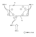
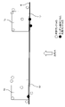
- FIG. 6 illustrates how target sample points belonging to the first surface 1br are obtained.
- FIG. 6 is a view of the first support 1b of FIG. 4 as viewed from above.
- Each white circle indicates the obtained target sample point.
- each target sample point is associated with the likelihood obtained in step S2.
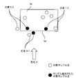
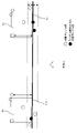
- the plane detection unit 103 randomly extracts at least three target sample points from the plurality of target sample points in the 3D coordinate information (see FIG. 7).
- the extraction is performed by RANSAC.
- the black circles are target sample points randomly selected.
- the number of target sample points randomly extracted is three. Note that the process of extracting the target sample points will be referred to as random extraction process.
- the plane detection unit 103 obtains a plane equation ⁇ (hereinafter simply referred to as plane ⁇ ) based on the three target sample points extracted above, for example, by RANSAC or the like. For example, here, it is assumed that a plane ⁇ 1 is obtained as the plane ⁇ .
- FIG. 8 illustrates the obtained plane ⁇ 1. Note that the process of obtaining the plane ⁇ will be referred to as a plane equation acquisition process.
- the plane detection unit 103 obtains the distances from the plane ⁇ 1 to each target sample point belonging to the first plane 1br.
- FIG. 9 exemplifies each determined distance d1, d2, d3, dn. In FIG. 9, only the distances d1, d2, d3, and dn are illustrated for the sake of simplification. A process for obtaining a distance is performed. In addition, suppose that the process which calculates
- plane detection section 103 determines that distances d1, d2, d3, and dn obtained above are less than threshold value t from among all target sample points (for example, all target sample points whose likelihood is greater than 0). (see FIG. 10).
- the distance to the threshold t is indicated by a dotted line.
- the threshold value t is a preset value, and as can be seen from FIG. 10, a dotted line is drawn at the position where the distance from the plane ⁇ 1, which is the current plane ⁇ , is the threshold value t. Therefore, in the processing here, the plane detection unit 103 extracts target sample points existing within the area surrounded by the dotted line in FIG. 10, for example. In the present embodiment, since it is "less than the threshold value t", the target sample points on the dotted line are not extracted.
- the plane detection unit 103 obtains the sum L of the likelihoods of all target sample points whose distance from the plane ⁇ 1 is less than the threshold value t. For example, in the example of FIG. 10, there are a total of 6 target sample points in the area enclosed by the dotted line. Therefore, the plane detection unit 103 extracts the six target sample points.
- likelihood values are assigned to the six target sample points. Therefore, in the case of the example of FIG. 10, the plane detection unit 103 obtains the added value L of the likelihood for the six target sample points. In the example of FIG. 10, likelihoods of 0.2, 0.2, 0.7, 0.7, 1.0, and 1.0 are given to each target sample point.
- the plane detection unit 103 compares the currently set provisional added value L' with the added value L of the likelihood obtained this time. Then, the larger value is newly set as the provisional added value L'.
- the provisional additional value L' currently set as the initial value is zero. Therefore, the added value L of the likelihood obtained this time is always larger than the provisional added value L' of the initial value. Therefore, the plane detection unit 103 sets the likelihood addition value L obtained this time as a new provisional addition value L'. In the case of the above example, 3.8 is set as the new provisional addition value L' in the plane detection device 10 .
- the plane detection unit 103 newly sets the plane ⁇ corresponding to the newly set provisional addition value L' as the provisional plane ⁇ ' in the plane detection device 10 .
- provisional value setting processing The processing of determining the size relationship between the provisional addition value L′ and the calculated likelihood addition value L, and the processing of newly setting the provisional addition value L′ and the provisional plane ⁇ ′ are referred to as provisional value setting processing. do.
- the plane setting loop is performed a predetermined number of times.
- the predetermined number of times may be set in advance in the plane detection device 10, for example. In this case, high accuracy can be achieved.
- the predetermined number of times can also be determined in an algorithm (see, for example, http://people.inf.ethz.ch/pomarc/pubs/RaguramPAMI13.pdf). In this case, higher speed processing becomes possible.
- it is assumed that k times are set in the plane detection device 10 as the predetermined number of plane setting loops.
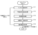
- FIG. 11 is a diagram showing the flow of the plane setting loop in step S3 of FIG.
- the plane setting loop includes random extraction processing S11, plane equation acquisition processing S12, distance acquisition processing S13, addition value L acquisition processing S14, and provisional value setting processing S15.
- the process returns from the provisional value setting process S15 to the random extraction process S11, and the next plane setting loop is executed. indicates that Furthermore, FIG. 11 shows that when the plane setting loop ends k times, the plane setting loop (in other words, the plane detection process in step S3 of FIG. 5) ends.
- the plane detection unit 103 randomly extracts three target sample points separately from the plurality of target sample points (see random extraction processing S11 in FIG. 11).
- the plane detection unit 103 obtains a plane ⁇ 2 as a plane equation based on the three target sample points extracted above, for example, by RANSAC (see plane equation acquisition processing S12 in FIG. 11).
- the plane detection unit 103 obtains the distances from the plane ⁇ 2 to each target sample point belonging to the first plane 1br (see distance acquisition processing S13 in FIG. 11).
- plane detection section 103 selects, from all target sample points (for example, all target sample points whose likelihood is greater than 0), target sample points whose distance obtained above is less than threshold value t. Extract. Then, the plane detection unit 103 obtains the added value L of the likelihoods of all target sample points whose distance from the plane ⁇ 2 is less than the threshold value t (see the added value L acquisition processing S14 in FIG. 11). For example, assume that 3.0 is obtained as the added value L of the likelihood in the second plane setting loop.
- the currently set provisional added value L′ is 3.8
- the likelihood added value L obtained in the second plane setting loop is 3.0. . Therefore, the plane detection unit 103 sets the currently set value as the new provisional addition value L'. That is, the value of 3.8 is continuously set as the provisional addition value L'.
- the plane detection unit 103 newly sets the plane ⁇ corresponding to the newly set provisional addition value L′ as the provisional plane ⁇ ′ in the plane detection device 10 (provisional value setting processing S15 in FIG. 11). reference).
- the process of the second plane setting loop is completed, and if the number of plane setting loops that have been completed up to this point is less than k, the process returns to step S11 to start the next plane setting loop.
- the plane setting loop illustrated in FIG. 11 ends k times
- the plane setting loop (in other words, plane detection processing in step S3 of FIG. 5) ends.
- the plane detection unit 103 outputs the provisional added value L' and the provisional plane ⁇ ' set at the time of completion as the plane detection result. That is, the output provisional plane ⁇ ' represents an equation for the plane detected from the object.
- plane detection apparatus 10 includes information acquisition section 101 , likelihood acquisition section 102 , and plane detection section 103 .
- the information acquisition unit 101 acquires visible image information of an object having a predetermined plane and 3D coordinate information corresponding to the visible image information.
- a likelihood acquisition unit 102 acquires a likelihood indicating the flatness of a predetermined plane of an object from the visible image information.
- the plane detection unit 103 uses the 3D coordinate information and the likelihood to detect a predetermined plane of the object by a robust estimation method.
- visible image information of an object having a predetermined plane and 3D coordinate information corresponding to the visible image information are obtained. Then, from the visible image information, the likelihood indicating the flatness of the predetermined plane of the object is acquired. Then, using the 3D coordinate information and the likelihood, a predetermined plane of the object is detected by a robust estimation method.
- the plane detection device 10 uses likelihood to detect a plane. Therefore, the predetermined plane of the object can be detected with higher precision than the conventional plane detection. For example, even if there is an occlusion object such as paper on the specific target plane, and multiple sample points are included that are distant from the specific target plane, the specified plane of the target can be robustly and accurately detected. can be detected.
- the ratio of the target sample points (in-range target sample points) included in the range whose distance from the plane ⁇ 1 is less than the threshold t that is, the ratio of the in-range target sample points to all the target sample points (For example, the plane with the largest ratio is detected as the predetermined plane of the object).
- information on likelihood is also used to detect a predetermined plane. Therefore, for example, when the number of loops of the RANSAC algorithm is set, high accuracy can be achieved, and on the other hand, when the predetermined number of times is obtained in the algorithm, speedup can be achieved.
- the plane detection device 10 further includes a storage unit 201 that stores a machine learning model constructed by machine learning. Then, the likelihood acquisition unit 102 acquires the likelihood for each pixel of the visible image information using the visible image information as input information and the machine learning model. Therefore, the likelihood acquisition unit 102 can acquire the likelihood of each pixel of the visible image information more quickly and with higher precision.
- the object includes the pallet 1 on which the object P can be loaded. Therefore, it is possible to detect the surface of the pallet 1 used in a factory or the like. Thereby, for example, it becomes possible to perform automatic control of each operation using the surface detection result.
- the pallet 1 includes a flat plate portion 1a and a first strut portion 1b.
- An object P is loaded on the flat plate portion 1a.
- the first column portion 1b extends from the flat plate portion 1a in the direction in which the object P is stacked.
- the predetermined plane includes the first surface 1br of the first support 1b. Therefore, when the pallet 1 has the first strut portion 1b extending in the vertical direction (the loading direction of the object P), the first surface 1br of the first strut portion 1b can be detected. can.
- plane detection section 103 uses a plurality of sample points randomly selected from 3D coordinate information and likelihoods corresponding to each of the plurality of sample points to , RANSAC to detect a given plane of the object. Therefore, it is possible to automatically detect the first surface 1br of the object in a highly accurate and practical manner.
- the case of detecting a predetermined plane including the first surface 1br of the pallet 1 has been described.
- a predetermined plane detection process will be described in the case where the pallet 1, which is an object, has, for example, two pillars (a first pillar portion and a second pillar portion). That is, in the present embodiment, when the first strut portion has the first surface and the second strut portion has the second surface, the first surface and the second surface are included.
- a case of detecting a predetermined plane will be described in detail.
- the object is a pallet 1 on which objects can be loaded.
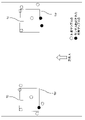
- FIG. 12 is a schematic diagram of the pallet 1 when viewed from the side (from direction A in FIG. 4, etc.).
- the pallet 1 includes a flat plate portion 1a, a first strut portion 1b, and a second strut portion 1c.
- the direction A is the direction from the front side to the back side of the paper surface in FIG. 12 .
- the first column portion 1b extends from the flat plate portion 1a in the stacking direction (vertical direction in FIG. 12).
- the first strut portion 1b has a first surface 1br on the opposite side of the space in which the object P is loaded. That is, the first surface 1br faces the outside of the pallet 1 (facing direction A).
- the second supporting column portion 1c extends from the flat plate portion 1a in the stacking direction (vertical direction in FIG. 12).
- the second strut portion 1c is arranged with respect to the flat plate portion 1a separately from the first strut portion 1b. That is, as illustrated in FIG.
- the second strut portion 1c is provided at a position separated from the first strut portion 1b.
- the second column portion 1c has a second surface 1cr on the opposite side of the space in which the object P is loaded. That is, the second surface 1cr faces the outside of the pallet 1 (facing direction A).
- the first surface 1br and the second surface 1cr are on the same plane. That is, in this embodiment, a predetermined plane having the first surface 1br and the second surface 1cr is detected.
- the second strut portion 1c may be a rectangular parallelepiped, but is not limited to this.
- the second supporting column 1c does not have to be a rectangular parallelepiped, as long as it has a flat area.
- the physical configuration of the flat surface detection device 10 is the same as that illustrated in the schematic block diagram of FIG.
- the plane detection apparatus 10 performs a series of processes in the same flow as in FIG. 5, and the plane detector 103 performs a series of processes in the same flow as in FIG. .
- the plane detection operation will be described below, focusing on the points of difference.
- a pallet 1 which is an object, has a first surface 1br and a second surface 1cr. A case of detecting a predetermined plane including the first surface 1br and the second surface 1cr will be described in detail below.
- provisional plane ⁇ ' the initial value provisional plane equation ⁇ ' (hereinafter referred to as provisional plane ⁇ ') (for example, a value such as 0 or null is set ).
- the imaging unit 40 images the pallet 1 .
- the information acquisition unit 101 acquires the visible image information of the palette 1 (see FIG. 2) and the 3D coordinate information (see FIG. 3) corresponding to the visible image information (step S1 in FIG. 5).
- the likelihood acquisition unit 102 acquires (calculates) the likelihoods of the first support 1b and the second support 1c from the visible image information (step S2 in FIG. 5).
- a method of acquiring the likelihood is the same as in the first embodiment.
- the likelihood is obtained for each pixel representing the first surface 1br of the first support 1b and each pixel representing the second surface 1cr of the second support 1c.
- the likelihood indicates the flatness of the first surface 1br of the first strut portion 1b and/or the flatness of the second surface 1cr of the second strut portion 1c. .
- the plane detection unit 103 uses the 3D coordinate information acquired by the information acquisition unit 101 and the likelihood acquired by the likelihood acquisition unit 102 to detect the predetermined plane by a robust estimation method (RANSAC). is detected (step S3 in FIG. 5).
- RANSAC robust estimation method
- the plane detection unit 103 obtains target sample points belonging to the first plane 1br in the 3D coordinate information acquired by the information acquisition unit 101 . Furthermore, the plane detection unit 103 obtains target sample points belonging to the second surface 1cr in the 3D coordinate information acquired by the information acquisition unit 101 . Note that the method of acquiring the target sample point is the same as in the first embodiment.
- FIG. 13 illustrates how the target sample points belonging to the first surface 1br and the target sample points belonging to the second surface 1cr are obtained.
- FIG. 13 is a top view of the first and second struts 1b and 1c. Each white circle indicates the obtained target sample point. Each target sample point is associated with the likelihood obtained in step S2 (FIG. 5).
- the plane detection unit 103 randomly extracts at least three target sample points from the plurality of target sample points in the 3D coordinate information (see random extraction processing S11 in FIG. 11 and FIG. 14).
- the extraction is performed by RANSAC.
- the black circles are randomly selected sample points of interest.
- the number of target sample points randomly extracted is three.
- the random extraction process S11 at least one target sample point belonging to the first plane 1br is selected, and at least one target sample point belonging to the second plane 1cr is selected. be.
- one target sample point belonging to the first plane 1br is selected, and two target sample points belonging to the second plane 1cr are selected.
- the plane detection unit 103 obtains a plane equation ⁇ (plane ⁇ ) by, for example, RANSAC or the like based on the three target sample points extracted above (see plane equation acquisition processing S12 in FIG. 11). .
- plane equation acquisition processing S12 in FIG. 11 it is assumed that a plane ⁇ i is obtained as the plane ⁇ .
- FIG. 15 illustrates the obtained plane ⁇ i.
- FIG. 16 illustrates the determined distance d.
- the distance d is illustrated for two target sample points for the sake of simplification. ,implement.
- the plane detection unit 103 selects target sample points (for example, all target sample points with a likelihood greater than 0) for which the distance d obtained above is less than the threshold value t. is extracted (see FIG. 17). As exemplified in FIG. 17, the distance to the threshold t is indicated by a dotted line. The plane detection unit 103 extracts target sample points that exist, for example, within the area surrounded by the dotted lines in FIG. In the present embodiment, since it is "less than the threshold value t", the target sample points on the dotted line are not extracted.
- target sample points for example, all target sample points with a likelihood greater than 0
- the plane detection unit 103 obtains the sum L of the likelihoods of all target sample points whose distance from the plane ⁇ i is less than the threshold value t (see sum L acquisition processing S14 in FIG. 11). For example, in the example of FIG. 17, there are a total of 6 target sample points in the area enclosed by the dotted line. Therefore, the plane detection unit 103 extracts the six target sample points. Assume that likelihoods of 0.3, 0.4, 0.7, 1.0, 1.0, and 1.0 are given to each target sample point. In this case, the plane detection unit 103 obtains 4.4 as the added value L of the likelihood.
- the plane detection unit 103 compares the currently set provisional added value L' with the added value L of the likelihood obtained this time. Then, the larger value is newly set as the provisional addition value L' (see provisional value setting processing S15 in FIG. 11).
- the provisional additional value L' currently set as the initial value is zero. Therefore, the plane detection unit 103 sets the likelihood addition value L obtained this time as a new provisional addition value L'.
- 4.4 is set as the new provisional addition value L' in the plane detection device 10 .
- the plane detection unit 103 newly sets the plane ⁇ corresponding to the newly set provisional addition value L′ as the provisional plane ⁇ ′ in the plane detection device 10 (provisional value setting processing S15 in FIG. 11). reference).
- step S3 of FIG. 5 the plane setting loop (see FIG. 11) is performed a predetermined number of times (k times).
- the process returns from the provisional value setting process S15 to the random extraction process S11, and the next plane setting loop is executed.
- the plane setting loop ends k times
- the plane setting loop (in other words, the plane detection process in step S3 of FIG. 5) ends.
- the plane detection unit 103 outputs the provisional added value L' and the provisional plane ⁇ ' set at the time of completion as the plane detection result. That is, the output provisional plane ⁇ ' represents an equation for the plane detected from the object.
- the pallet 1 includes a second strut portion 1c apart from the first strut portion 1b.
- the second strut portion 1c extends from the flat plate portion 1a in the direction in which objects are stacked (vertical direction in FIG. 12).
- the second strut portion 1c includes a second surface 1cr.
- the predetermined plane has a first surface 1br and a second surface 1cr.
- the pallet 1 has first and second struts 1b and 1c extending in the vertical direction (object loading direction), and the first surface 1br and the second surface 1cr are coplanar. , a predetermined plane (a plane including the first plane 1br and the second plane 1cr) can be detected with respect to the object pallet 1 .
- plane detection section 103 uses a plurality of sample points randomly selected from 3D coordinate information and likelihoods corresponding to each of the plurality of sample points to , RANSAC to detect a given plane of the pallet 1 . At least one sample point is selected for the first surface 1br, and at least one sample point is selected for the second surface 1cr.
- the first and second surfaces 1br, 1cr of the pallet 1 can be detected automatically, highly accurately, and practically. Furthermore, since the first surface 1br and the second surface 1cr are arranged apart from each other, and the first surface 1br and the second surface 1cr are in the same plane, only the first surface 1br is targeted. As a result, the predetermined plane can be detected at a higher speed and with a higher degree of accuracy than when the predetermined plane is detected.
- the present disclosure can, for example, easily measure a predetermined surface of a pallet with high accuracy, and can be suitable for the field of transportation such as loading cargo on trucks and warehouses.
Landscapes
- Engineering & Computer Science (AREA)
- Physics & Mathematics (AREA)
- General Physics & Mathematics (AREA)
- Computer Vision & Pattern Recognition (AREA)
- Theoretical Computer Science (AREA)
- Geometry (AREA)
- Probability & Statistics with Applications (AREA)
- Software Systems (AREA)
- Length Measuring Devices By Optical Means (AREA)
Priority Applications (3)
| Application Number | Priority Date | Filing Date | Title |
|---|---|---|---|
| CN202280024975.0A CN117063042A (zh) | 2021-03-31 | 2022-03-09 | 平面检测装置以及平面检测方法 |
| JP2023510778A JP7777736B2 (ja) | 2021-03-31 | 2022-03-09 | 平面検出装置および平面検出方法 |
| US18/372,066 US20240013421A1 (en) | 2021-03-31 | 2023-09-23 | Plane detecting device, and plane detecting method |
Applications Claiming Priority (2)
| Application Number | Priority Date | Filing Date | Title |
|---|---|---|---|
| JP2021061257 | 2021-03-31 | ||
| JP2021-061257 | 2021-03-31 |
Related Child Applications (1)
| Application Number | Title | Priority Date | Filing Date |
|---|---|---|---|
| US18/372,066 Continuation US20240013421A1 (en) | 2021-03-31 | 2023-09-23 | Plane detecting device, and plane detecting method |
Publications (1)
| Publication Number | Publication Date |
|---|---|
| WO2022209668A1 true WO2022209668A1 (ja) | 2022-10-06 |
Family
ID=83458869
Family Applications (1)
| Application Number | Title | Priority Date | Filing Date |
|---|---|---|---|
| PCT/JP2022/010326 Ceased WO2022209668A1 (ja) | 2021-03-31 | 2022-03-09 | 平面検出装置および平面検出方法 |
Country Status (4)
| Country | Link |
|---|---|
| US (1) | US20240013421A1 (https=) |
| JP (1) | JP7777736B2 (https=) |
| CN (1) | CN117063042A (https=) |
| WO (1) | WO2022209668A1 (https=) |
Citations (3)
| Publication number | Priority date | Publication date | Assignee | Title |
|---|---|---|---|---|
| JP2017151652A (ja) * | 2016-02-23 | 2017-08-31 | 村田機械株式会社 | 物体状態特定方法、物体状態特定装置、および、搬送車 |
| JP2019032773A (ja) * | 2017-08-09 | 2019-02-28 | キヤノン株式会社 | 画像処理装置、画像処理方法 |
| JP2021042070A (ja) * | 2019-09-13 | 2021-03-18 | 株式会社豊田自動織機 | 位置姿勢推定装置 |
Family Cites Families (7)
| Publication number | Priority date | Publication date | Assignee | Title |
|---|---|---|---|---|
| EP2154650A1 (en) * | 2008-08-12 | 2010-02-17 | IEE INTERNATIONAL ELECTRONICS & ENGINEERING S.A. | 3D time-of-flight camera system and position/orientation calibration method therefor |
| US8872851B2 (en) * | 2010-09-24 | 2014-10-28 | Intel Corporation | Augmenting image data based on related 3D point cloud data |
| US20160189419A1 (en) * | 2013-08-09 | 2016-06-30 | Sweep3D Corporation | Systems and methods for generating data indicative of a three-dimensional representation of a scene |
| DE112017001322T5 (de) * | 2016-03-16 | 2018-12-27 | Sony Corporation | Signalverarbeitungsvorrichtung und Signalverarbeitungsverfahren |
| CN108053491A (zh) * | 2017-12-12 | 2018-05-18 | 重庆邮电大学 | 动态视角条件下实现平面目标三维跟踪和增强现实的方法 |
| US10346987B1 (en) * | 2017-12-29 | 2019-07-09 | Datalogic Usa, Inc. | Locating objects on surfaces |
| US11107238B2 (en) * | 2019-12-13 | 2021-08-31 | Zebra Technologies Corporation | Method, system and apparatus for detecting item facings |
-
2022
- 2022-03-09 CN CN202280024975.0A patent/CN117063042A/zh active Pending
- 2022-03-09 WO PCT/JP2022/010326 patent/WO2022209668A1/ja not_active Ceased
- 2022-03-09 JP JP2023510778A patent/JP7777736B2/ja active Active
-
2023
- 2023-09-23 US US18/372,066 patent/US20240013421A1/en active Pending
Patent Citations (3)
| Publication number | Priority date | Publication date | Assignee | Title |
|---|---|---|---|---|
| JP2017151652A (ja) * | 2016-02-23 | 2017-08-31 | 村田機械株式会社 | 物体状態特定方法、物体状態特定装置、および、搬送車 |
| JP2019032773A (ja) * | 2017-08-09 | 2019-02-28 | キヤノン株式会社 | 画像処理装置、画像処理方法 |
| JP2021042070A (ja) * | 2019-09-13 | 2021-03-18 | 株式会社豊田自動織機 | 位置姿勢推定装置 |
Also Published As
| Publication number | Publication date |
|---|---|
| US20240013421A1 (en) | 2024-01-11 |
| JP7777736B2 (ja) | 2025-12-01 |
| CN117063042A (zh) | 2023-11-14 |
| JPWO2022209668A1 (https=) | 2022-10-06 |
Similar Documents
| Publication | Publication Date | Title |
|---|---|---|
| US10880541B2 (en) | Stereo correspondence and depth sensors | |
| US10346987B1 (en) | Locating objects on surfaces | |
| US9135710B2 (en) | Depth map stereo correspondence techniques | |
| US10249052B2 (en) | Stereo correspondence model fitting | |
| US10424078B2 (en) | Height measuring system and method | |
| US9208547B2 (en) | Stereo correspondence smoothness tool | |
| JP6589636B2 (ja) | 3次元形状計測装置、3次元形状計測方法及び3次元形状計測プログラム | |
| US20210207943A1 (en) | Measurement device and measurement method | |
| US10462450B2 (en) | Combining two-dimensional images with depth data to detect junctions or edges | |
| RU2013140835A (ru) | Устройство обработки изображения, способ обработки изображения и программа | |
| CN106575193A (zh) | 用于深度摄影系统中的图像位置选择 | |
| CN103292725A (zh) | 特殊边界量测系统及方法 | |
| JP6573196B2 (ja) | 距離情報補正装置、距離情報補正方法及び距離情報補正プログラム | |
| US9912934B2 (en) | Determining three dimensional information using a single camera | |
| JP2018172847A (ja) | 検査支援装置、検査支援方法及びプログラム | |
| JP2022105442A (ja) | 情報処理装置、情報処理方法およびプログラム | |
| US12469158B2 (en) | Measurement device and measurement method | |
| US10068339B2 (en) | Image processing device, image processing system, image processing method and image processing program | |
| CN104915948B (zh) | 用于使用范围传感器选择二维兴趣区域的系统和方法 | |
| JP7777736B2 (ja) | 平面検出装置および平面検出方法 | |
| US20180124381A1 (en) | Structured-light-based three-dimensional scanning method, apparatus and system thereof | |
| EP4466668A1 (en) | Sensor calibration system | |
| US20160217559A1 (en) | Two-dimensional image processing based on third dimension data | |
| TWI382150B (zh) | 目標物距離偵測方法與裝置及其電腦程式產品 | |
| JP7582460B2 (ja) | 撮影条件決定方法、撮影条件決定システム、撮影条件決定装置、及びプログラム |
Legal Events
| Date | Code | Title | Description |
|---|---|---|---|
| 121 | Ep: the epo has been informed by wipo that ep was designated in this application |
Ref document number: 22779891 Country of ref document: EP Kind code of ref document: A1 |
|
| WWE | Wipo information: entry into national phase |
Ref document number: 2023510778 Country of ref document: JP |
|
| WWE | Wipo information: entry into national phase |
Ref document number: 202280024975.0 Country of ref document: CN |
|
| NENP | Non-entry into the national phase |
Ref country code: DE |
|
| 122 | Ep: pct application non-entry in european phase |
Ref document number: 22779891 Country of ref document: EP Kind code of ref document: A1 |