WO2022209362A1 - Image processing device, image processing method, and program - Google Patents
Image processing device, image processing method, and program Download PDFInfo
- Publication number
- WO2022209362A1 WO2022209362A1 PCT/JP2022/005748 JP2022005748W WO2022209362A1 WO 2022209362 A1 WO2022209362 A1 WO 2022209362A1 JP 2022005748 W JP2022005748 W JP 2022005748W WO 2022209362 A1 WO2022209362 A1 WO 2022209362A1
- Authority
- WO
- WIPO (PCT)
- Prior art keywords
- image
- virtual viewpoint
- viewpoint
- information
- video
- Prior art date
Links
- 238000012545 processing Methods 0.000 title claims abstract description 293
- 238000003672 processing method Methods 0.000 title description 6
- 238000003384 imaging method Methods 0.000 claims description 66
- 230000004044 response Effects 0.000 claims description 3
- 238000005516 engineering process Methods 0.000 description 83
- 238000000034 method Methods 0.000 description 59
- 238000003860 storage Methods 0.000 description 58
- 230000008569 process Effects 0.000 description 42
- 238000010586 diagram Methods 0.000 description 40
- 238000000605 extraction Methods 0.000 description 33
- 240000004050 Pentaglottis sempervirens Species 0.000 description 32
- 235000004522 Pentaglottis sempervirens Nutrition 0.000 description 32
- 230000005540 biological transmission Effects 0.000 description 26
- 230000006870 function Effects 0.000 description 18
- 238000004891 communication Methods 0.000 description 16
- 239000000470 constituent Substances 0.000 description 6
- 102100029860 Suppressor of tumorigenicity 20 protein Human genes 0.000 description 5
- 238000004364 calculation method Methods 0.000 description 5
- 239000000284 extract Substances 0.000 description 4
- 238000004549 pulsed laser deposition Methods 0.000 description 3
- 230000009471 action Effects 0.000 description 2
- 238000009795 derivation Methods 0.000 description 2
- 230000000694 effects Effects 0.000 description 2
- 230000003287 optical effect Effects 0.000 description 2
- 238000003825 pressing Methods 0.000 description 2
- 238000010079 rubber tapping Methods 0.000 description 2
- 239000004065 semiconductor Substances 0.000 description 2
- 238000013473 artificial intelligence Methods 0.000 description 1
- 230000000386 athletic effect Effects 0.000 description 1
- 230000001413 cellular effect Effects 0.000 description 1
- 230000008859 change Effects 0.000 description 1
- 238000006243 chemical reaction Methods 0.000 description 1
- 230000000295 complement effect Effects 0.000 description 1
- 238000005401 electroluminescence Methods 0.000 description 1
- 238000009434 installation Methods 0.000 description 1
- 239000004973 liquid crystal related substance Substances 0.000 description 1
- 230000007774 longterm Effects 0.000 description 1
- 238000004519 manufacturing process Methods 0.000 description 1
- 229910044991 metal oxide Inorganic materials 0.000 description 1
- 150000004706 metal oxides Chemical class 0.000 description 1
- 230000004048 modification Effects 0.000 description 1
- 238000012986 modification Methods 0.000 description 1
- 238000005070 sampling Methods 0.000 description 1
- 239000007787 solid Substances 0.000 description 1
- 230000009182 swimming Effects 0.000 description 1
- 238000012546 transfer Methods 0.000 description 1
Images


Classifications
-
- G—PHYSICS
- G06—COMPUTING; CALCULATING OR COUNTING
- G06T—IMAGE DATA PROCESSING OR GENERATION, IN GENERAL
- G06T15/00—3D [Three Dimensional] image rendering
- G06T15/10—Geometric effects
- G06T15/20—Perspective computation
- G06T15/205—Image-based rendering
-
- H—ELECTRICITY
- H04—ELECTRIC COMMUNICATION TECHNIQUE
- H04N—PICTORIAL COMMUNICATION, e.g. TELEVISION
- H04N21/00—Selective content distribution, e.g. interactive television or video on demand [VOD]
- H04N21/20—Servers specifically adapted for the distribution of content, e.g. VOD servers; Operations thereof
- H04N21/21—Server components or server architectures
- H04N21/218—Source of audio or video content, e.g. local disk arrays
- H04N21/21805—Source of audio or video content, e.g. local disk arrays enabling multiple viewpoints, e.g. using a plurality of cameras
-
- H—ELECTRICITY
- H04—ELECTRIC COMMUNICATION TECHNIQUE
- H04N—PICTORIAL COMMUNICATION, e.g. TELEVISION
- H04N21/00—Selective content distribution, e.g. interactive television or video on demand [VOD]
- H04N21/40—Client devices specifically adapted for the reception of or interaction with content, e.g. set-top-box [STB]; Operations thereof
- H04N21/41—Structure of client; Structure of client peripherals
- H04N21/4104—Peripherals receiving signals from specially adapted client devices
- H04N21/4122—Peripherals receiving signals from specially adapted client devices additional display device, e.g. video projector
-
- H—ELECTRICITY
- H04—ELECTRIC COMMUNICATION TECHNIQUE
- H04N—PICTORIAL COMMUNICATION, e.g. TELEVISION
- H04N21/00—Selective content distribution, e.g. interactive television or video on demand [VOD]
- H04N21/60—Network structure or processes for video distribution between server and client or between remote clients; Control signalling between clients, server and network components; Transmission of management data between server and client, e.g. sending from server to client commands for recording incoming content stream; Communication details between server and client
- H04N21/65—Transmission of management data between client and server
- H04N21/658—Transmission by the client directed to the server
- H04N21/6587—Control parameters, e.g. trick play commands, viewpoint selection
-
- H—ELECTRICITY
- H04—ELECTRIC COMMUNICATION TECHNIQUE
- H04N—PICTORIAL COMMUNICATION, e.g. TELEVISION
- H04N5/00—Details of television systems
- H04N5/222—Studio circuitry; Studio devices; Studio equipment
- H04N5/262—Studio circuits, e.g. for mixing, switching-over, change of character of image, other special effects ; Cameras specially adapted for the electronic generation of special effects
- H04N5/2628—Alteration of picture size, shape, position or orientation, e.g. zooming, rotation, rolling, perspective, translation
-
- G—PHYSICS
- G06—COMPUTING; CALCULATING OR COUNTING
- G06T—IMAGE DATA PROCESSING OR GENERATION, IN GENERAL
- G06T2200/00—Indexing scheme for image data processing or generation, in general
- G06T2200/24—Indexing scheme for image data processing or generation, in general involving graphical user interfaces [GUIs]
-
- H—ELECTRICITY
- H04—ELECTRIC COMMUNICATION TECHNIQUE
- H04N—PICTORIAL COMMUNICATION, e.g. TELEVISION
- H04N21/00—Selective content distribution, e.g. interactive television or video on demand [VOD]
- H04N21/40—Client devices specifically adapted for the reception of or interaction with content, e.g. set-top-box [STB]; Operations thereof
- H04N21/43—Processing of content or additional data, e.g. demultiplexing additional data from a digital video stream; Elementary client operations, e.g. monitoring of home network or synchronising decoder's clock; Client middleware
- H04N21/4302—Content synchronisation processes, e.g. decoder synchronisation
- H04N21/4307—Synchronising the rendering of multiple content streams or additional data on devices, e.g. synchronisation of audio on a mobile phone with the video output on the TV screen
- H04N21/43079—Synchronising the rendering of multiple content streams or additional data on devices, e.g. synchronisation of audio on a mobile phone with the video output on the TV screen of additional data with content streams on multiple devices
-
- H—ELECTRICITY
- H04—ELECTRIC COMMUNICATION TECHNIQUE
- H04N—PICTORIAL COMMUNICATION, e.g. TELEVISION
- H04N21/00—Selective content distribution, e.g. interactive television or video on demand [VOD]
- H04N21/40—Client devices specifically adapted for the reception of or interaction with content, e.g. set-top-box [STB]; Operations thereof
- H04N21/43—Processing of content or additional data, e.g. demultiplexing additional data from a digital video stream; Elementary client operations, e.g. monitoring of home network or synchronising decoder's clock; Client middleware
- H04N21/436—Interfacing a local distribution network, e.g. communicating with another STB or one or more peripheral devices inside the home
- H04N21/43615—Interfacing a Home Network, e.g. for connecting the client to a plurality of peripherals
Definitions
- the technology of the present disclosure relates to an image processing device, an image processing method, and a program.
- Japanese Unexamined Patent Application Publication No. 2018-046448 describes a movement trajectory of a virtual camera in an image processing device that generates a free-viewpoint video, which is a video viewed from a virtual camera, from multi-viewpoint video captured using a plurality of cameras.
- a user interface for specifying a camera path and a point-of-regard path indicating a trajectory of movement of a point-of-regard to which a virtual camera gazes; and generating means for generating a free-viewpoint video, and the user interface displays the free-viewpoint video of the multi-viewpoint video on a UI screen using a two-dimensional image that captures a bird's-eye view of the shooting scene of the multi-viewpoint video.
- a featured image processing apparatus is disclosed. Further, in the image processing device described in Japanese Patent Application Laid-Open No. 2018-046448, the two-dimensional image is a still image, and the user interface displays each subject in a predetermined frame obtained by sampling the time frame at regular intervals along the time axis. It is configured to display changes in the time series of the subject by superimposing them on the still image in different modes. Further, in the image processing apparatus disclosed in Japanese Patent Application Laid-Open No.
- the user interface arranges thumbnail images as seen from the virtual camera at regular intervals in the time axis direction along the camera path specified by the user.
- the route, altitude, and moving speed of the virtual camera are adjusted through user's input operation on the thumbnail image.
- Japanese Patent Application Laid-Open No. 2017-212592 describes a system in which virtual viewpoint images are generated by an image generation device based on image data captured by a plurality of cameras for capturing images of a subject from a plurality of directions. and a restricted area in which the designation of the viewpoint based on the instruction received by the receiving means is restricted, the operating state and image of the device included in the system Acquisition means for acquiring information for identifying a restricted area that changes according to at least one of the parameters related to data; and a display unit that displays an image based on display control according to the restricted area based on the information acquired by the acquisition means and a display control means for displaying on.
- a display control unit of any one of the imaging devices selected by the user controls moving images captured by a plurality of imaging devices. It is described that a list of thumbnail images corresponding to images may be displayed, and reproduction may be started from one selected by the user.
- An embodiment according to the technology of the present disclosure provides an image processing device, an image processing method, and a program capable of showing a viewer a representative image corresponding to a virtual viewpoint video.
- a first aspect of the technology of the present disclosure includes a processor and a memory connected to or built into the processor, and the processor captures a plurality of captured images and a plurality of viewpoint information obtained by capturing an imaging region.
- a representative image corresponding to the virtual viewpoint video generated based on is obtained based on a plurality of captured images and a plurality of viewpoint information, and the representative image is displayed on a display in a size different from that of the virtual viewpoint video. It is an image processing device that outputs data.
- a second aspect of the technology of the present disclosure is the first aspect, wherein the representative image is an image related to a first frame among a plurality of frames including the first subject in the imaging area in the virtual viewpoint video. It is an image processing apparatus according to.
- a third aspect of the technology of the present disclosure is the image processing device according to the second aspect, wherein the first subject is a subject determined based on the time included in the virtual viewpoint video.
- a fourth aspect of the technology of the present disclosure is an image according to the second aspect or the third aspect, wherein the first frame is a frame determined based on the size of the first subject in the virtual viewpoint video. processing equipment.
- a fifth aspect of the technology of the present disclosure is image processing according to any one aspect of the first aspect to the fourth aspect, wherein the processor obtains a representative image based on editing results of a plurality of pieces of viewpoint information. It is a device.
- a sixth aspect according to the technology of the present disclosure is the fifth aspect, wherein the plurality of viewpoint information has a plurality of viewpoint paths, and the editing result includes a result of editing performed on the plurality of viewpoint paths. It is an image processing apparatus according to.
- a seventh aspect of the technology of the present disclosure is the image according to any one aspect of the first to sixth aspects, wherein the processor acquires a representative image based on the degree of difference between a plurality of pieces of viewpoint information. processing equipment.
- An eighth aspect of the technology of the present disclosure is the image processing device according to the seventh aspect, wherein the plurality of viewpoint information has a plurality of viewpoint paths, and the degree of difference is a degree of difference between the plurality of viewpoint paths. is.
- a ninth aspect of the technology of the present disclosure is from the first aspect, wherein the plurality of viewpoint information has a plurality of viewpoint paths, and the processor acquires the representative image based on the positional relationship of the plurality of viewpoint paths.
- This is an image processing device according to any one aspect of the eighth aspect.
- a tenth aspect of the technology of the present disclosure is the image processing device according to the ninth aspect, wherein the positional relationship is the positional relationship of a plurality of viewpoint paths with respect to the second subject within the imaging area.
- a processor searches for a search condition-matching virtual viewpoint video that matches a given search condition from a plurality of virtual viewpoint videos, and performs a representative search based on the search condition-matching virtual viewpoint video.
- An image processing apparatus for acquiring an image according to any one of the first to tenth aspects.
- a twelfth aspect of the technology of the present disclosure is any one of the first to eleventh aspects, wherein the representative image is an image determined according to the situation of the third subject within the imaging area. It is an image processing apparatus according to.
- a thirteenth aspect of the technology of the present disclosure is any one of the first aspect to the twelfth aspect, wherein the representative image is an image determined according to an attribute of a person involved in the virtual viewpoint video. This is the image processing apparatus.
- a fourteenth aspect of the technology of the present disclosure is the image processing device according to any one of the first to thirteenth aspects, wherein the representative image is an image representing the content of the virtual viewpoint video.
- the plurality of viewpoint information includes first viewpoint information and second viewpoint information from different viewpoints, and the first viewpoint information and the second viewpoint information have information about different times. and an image processing apparatus according to any one of the first to fourteenth aspects.
- a sixteenth aspect of the technology of the present disclosure is that the processor outputs first data for displaying the representative image on the first display, and the representative image displayed on the first display is selected.
- any one of the first aspect to the fifteenth aspect, wherein the second data for displaying the virtual viewpoint video corresponding to the representative image on at least one of the first display and the second display according to the 1 is an image processing apparatus according to one aspect;
- a seventeenth aspect of the technology of the present disclosure is an image according to any one of the first aspect to the sixteenth aspect, wherein the processor stores the representative image and the virtual viewpoint video in a memory in a state of being associated with each other. processing equipment.
- An eighteenth aspect of the technology of the present disclosure includes a processor and a memory connected to or built into the processor, wherein the processor captures a plurality of captured images and a plurality of viewpoint information obtained by capturing an imaging region. Acquiring a representative image corresponding to the virtual viewpoint video generated based on based on the plurality of captured images and the plurality of viewpoint information, and obtaining data for displaying the representative image on the screen on which the plurality of images are displayed It is an image processing device for output.
- a representative image corresponding to a virtual viewpoint video generated based on a plurality of captured images obtained by capturing an imaging region and a plurality of pieces of viewpoint information is generated from a plurality of An image processing method including acquiring based on a captured image and a plurality of viewpoint information, and outputting data for displaying a representative image on a display in a size different from that of a virtual viewpoint video.
- a twentieth aspect of the technology of the present disclosure provides a computer with a representative image corresponding to a virtual viewpoint video generated based on a plurality of captured images obtained by capturing an imaging region and a plurality of viewpoint information. , acquisition based on a plurality of captured images and a plurality of viewpoint information, and outputting data for displaying a representative image on a display in a size different from that of the virtual viewpoint video. It's a program.
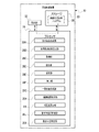
- FIG. 1 is a conceptual diagram showing an example of the configuration of an image processing system
- FIG. It is a block diagram which shows an example of the hardware configuration of the electrical system of a user device.
- 2 is a block diagram showing an example of functions of a main part of a CPU of the image processing apparatus;
- FIG. 4 is a conceptual diagram showing an example of processing contents of a reception screen generation unit and an example of display contents of a display of a user device;
- FIG. 10 is a screen diagram showing an example of a display mode of a reception screen when the operation mode of the user device is the viewpoint setting mode;
- FIG. 11 is a screen diagram showing an example of a display mode of a reception screen when the operation mode of the user device is the point-of-regard setting mode;
- 3 is a block diagram showing an example of contents of viewpoint information and an example of a mode in which viewpoint information is transmitted from a user device to an image processing apparatus;
- FIG. FIG. 4 is a conceptual diagram showing an example of processing contents of a virtual viewpoint video generation unit; 4 is a conceptual diagram showing an example of processing contents of an acquisition unit, an extraction unit, a selection unit, and a processing unit;
- FIG. 5 is a conceptual diagram showing an example of processing contents of a processing unit and a list screen generation unit; 7 is a flowchart showing an example of the flow of screen generation processing; 2 is a block diagram showing an example of functions of a main part of a CPU of the image processing apparatus; FIG. FIG. 4 is a conceptual diagram showing an example of a manner in which a viewpoint path is edited; 3 is a block diagram showing an example of contents of viewpoint information and an example of a mode in which viewpoint information is transmitted from a user device to an image processing apparatus; FIG. FIG. 4 is a conceptual diagram showing an example of processing contents of a virtual viewpoint video generation unit; FIG.
- FIG. 10 is a conceptual diagram showing an example of processing contents of an edit result processing unit
- 4 is a conceptual diagram showing an example of processing contents of an acquisition unit, an extraction unit, a selection unit, and a processing unit
- FIG. FIG. 5 is a conceptual diagram showing an example of processing contents of a processing unit and a list screen generation unit
- 2 is a block diagram showing an example of functions of a main part of a CPU of the image processing apparatus
- FIG. FIG. 4 is a conceptual diagram showing an example of a manner in which a first viewpoint path and a second viewpoint path are specified by a user
- 4 is a conceptual diagram showing an example of contents of first viewpoint path information and contents of second viewpoint path information
- FIG. 4 is a block diagram showing an example of a manner in which first viewpoint path information and second viewpoint path information are transmitted from a user device to an image processing apparatus;
- FIG. 4 is a conceptual diagram showing an example of processing contents of a virtual viewpoint video generation unit;
- FIG. 4 is a conceptual diagram showing an example of a manner in which a first virtual viewpoint video and a second virtual viewpoint video are stored in a storage;
- FIG. 10 is a conceptual diagram showing an example of processing contents of a dissimilarity calculation unit;
- FIG. 4 is a conceptual diagram showing an example of a manner in which a first virtual viewpoint video is processed by an acquisition unit, an extraction unit, a selection unit, and a processing unit;
- FIG. 4 is a block diagram showing an example of a manner in which first viewpoint path information and second viewpoint path information are transmitted from a user device to an image processing apparatus;
- FIG. 4 is a conceptual diagram showing an example of processing contents of a virtual viewpoint video generation unit;
- FIG. 4 is a conceptual diagram showing an example
- FIG. 9 is a conceptual diagram showing an example of a mode in which a second virtual viewpoint video is processed by an acquisition unit, an extraction unit, a selection unit, and a processing unit;
- 2 is a block diagram showing an example of functions of a main part of a CPU of the image processing apparatus;
- FIG. 4 is a block diagram showing an example of a manner in which first viewpoint path information and second viewpoint path information are transmitted from a user device to an image processing apparatus;
- FIG. 4 is a conceptual diagram showing an example of processing contents of a subject position specifying unit;
- FIG. 4 is a conceptual diagram showing an example of processing contents of a viewpoint position specifying unit;
- FIG. 4 is a conceptual diagram showing an example of a manner in which a first virtual viewpoint video is processed by an acquisition unit and a processing unit;
- FIG. 10 is a conceptual diagram showing an example of a mode in which a second virtual viewpoint video is processed by an acquisition unit and a processing unit;
- 2 is a block diagram showing an example of functions of a main part of a CPU of the image processing apparatus;
- FIG. 4 is a conceptual diagram showing an example of processing contents of a search condition providing unit and an acquisition unit;
- FIG. 2 is a block diagram showing an example of functions of a main part of a CPU of the image processing apparatus;
- FIG. 4 is a conceptual diagram showing an example of processing contents of a situation recognition unit and an acquisition unit;
- FIG. 2 is a block diagram showing an example of functions of a main part of a CPU of the image processing apparatus;
- FIG. FIG. 3 is a conceptual diagram showing an example of processing contents of a person-attribute subject recognition unit and an acquisition unit;
- 4 is a conceptual diagram showing an example of contents of first viewpoint path information and contents of second viewpoint path information;
- FIG. FIG. 2 is a conceptual diagram showing an example of a mode in which a screen generation processing program stored in a storage medium is installed in a computer of an image processing apparatus;
- CPU is an abbreviation for "Central Processing Unit”.
- GPU is an abbreviation for "Graphics Processing Unit”.
- TPU is an abbreviation for "Tensor processing unit”.
- RAM is an abbreviation for "Random Access Memory”.
- SSD is an abbreviation for "Solid State Drive”.
- HDD is an abbreviation for "Hard Disk Drive”.
- EEPROM is an abbreviation for "Electrically Erasable and Programmable Read Only Memory”.
- I/F is an abbreviation for "Interface”.
- ASIC is an abbreviation for "Application Specific Integrated Circuit”.
- PLD is an abbreviation for "Programmable Logic Device”.
- FPGA is an abbreviation for "Field-Programmable Gate Array”.
- SoC is an abbreviation for "System-on-a-chip.”
- CMOS is an abbreviation for "Complementary Metal Oxide Semiconductor”.
- CCD is an abbreviation for "Charge Coupled Device”.
- EL is an abbreviation for "Electro-Luminescence”.
- LAN is an abbreviation for "Local Area Network”.
- USB is an abbreviation for "Universal Serial Bus”.
- HMD is an abbreviation for “Head Mounted Display”.
- LTE is an abbreviation for “Long Term Evolution”.
- 5G is an abbreviation for “5th generation (wireless technology for digital cellular networks)”.
- TDM is an abbreviation for "Time-Division Multiplexing”.
- AI is an abbreviation for “Artificial Intelligence”. Also, in this specification, a subject included in an image (an image in the sense of including a still image and a moving image) refers to a subject included in the image as an image (for example, an electronic image).
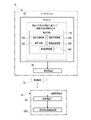
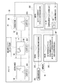
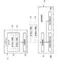
- the image processing system 2 includes an image processing device 10 and a user device 12 .
- a server is applied as an example of the image processing apparatus 10 in the first embodiment.
- a server is implemented by, for example, a mainframe.
- the server may be implemented by network computing such as cloud computing, fog computing, edge computing, or grid computing.
- the image processing apparatus 10 may be a plurality of servers, a workstation, a personal computer, or a combination of at least one workstation and at least one personal computer. It may also be a device that combines at least one work station, at least one personal computer, and at least one server.
- a smart phone is applied as an example of the user device 12 .
- the smart phone is merely an example, and may be, for example, a personal computer or a portable multifunctional terminal such as a tablet terminal or an HMD.
- the image processing apparatus 10 and the user device 12 are communicably connected via a base station (not shown), for example.
- Communication standards used in base stations include wireless communication standards including 5G standards and/or LTE standards, wireless communication standards including WiFi (802.11) standards and/or Bluetooth (registered trademark) standards, and TDM standards. and/or wireline communication standards, including the Ethernet standard.
- the image processing device 10 acquires an image and transmits the acquired image to the user device 12.
- the image refers to, for example, a captured image 64 (see FIG. 4) obtained by capturing an image, an image generated based on the captured image 64 (see FIG. 4, etc.), and the like.
- An example of the image generated based on the captured image (see FIG. 4) is the virtual viewpoint image 76 (see FIG. 8, etc.).
- the user device 12 is used by the user 14.
- the user device 12 has a touch panel display 16 .
- the touch panel display 16 is implemented by a display 18 and a touch panel 20 .
- An example of the display 18 is an EL display (eg, an organic EL display or an inorganic EL display). Note that the display is not limited to the EL display, and other types of display such as a liquid crystal display may be used.
- the touch panel display 16 is formed by overlaying the touch panel 20 on the display area of the display 18, or by making the display 18 an in-cell type in which the touch panel function is built inside.
- the in-cell type is merely an example, and may be an out-cell type or an on-cell type.
- the user device 12 executes processing according to instructions received from the user via the touch panel 20 or the like.
- the user device 12 exchanges various information with the image processing apparatus 10 according to instructions received from the user through the touch panel 20 or the like.
- the user device 12 receives the image transmitted from the image processing device 10 and causes the display 18 to display the received image.
- User 14 views the image displayed on display 18 .
- the image processing apparatus 10 includes a computer 22, a transmission/reception device 24, and a communication I/F 26.
- the computer 22 is an example of a “computer” according to the technology of the present disclosure, and includes a processor 28 , storage 30 and RAM 32 .
- the image processing device 10 includes a bus 34 through which the processor 28 , storage 30 and RAM 32 are connected. In the example shown in FIG. 1, one bus is illustrated as the bus 34 for convenience of illustration, but a plurality of buses may be used.
- the bus 34 may also include a serial bus or a parallel bus composed of a data bus, an address bus, a control bus, and the like.
- the processor 28 is an example of a "processor" according to the technology of the present disclosure.
- the processor 28 controls the entire image processing device 10 .
- processor 28 includes a CPU and a GPU, which operates under control of the CPU and is responsible for performing image processing.
- the storage 30 stores various parameters, various programs, and the like. Examples of storage 30 include EEPROM, SSD, and/or HDD.
- the storage 30 is an example of "memory" according to the technology of the present disclosure. Various information is temporarily stored in the RAM 32 . RAM 32 is used by processor 28 as a work memory.
- the transmitting/receiving device 24 is connected to the bus 34 .
- the transmitting/receiving device 24 is a device including a communication processor (not shown), an antenna, etc. Under the control of the processor 28, the transmitting/receiving device 24 transmits/receives various information to/from the user device 12 via a base station (not shown). . That is, the processor 28 exchanges various information with the user device 12 via the transmitter/receiver 24 .
- the communication I/F 26 is implemented, for example, by a device having an FPGA.
- the communication I/F 26 is connected to a plurality of imaging devices 36 via LAN cables (not shown).
- the imaging device 36 is an imaging device having a CMOS image sensor, and is equipped with an optical zoom function and/or a digital zoom function. Note that another type of image sensor such as a CCD image sensor may be employed instead of the CMOS image sensor.
- the plurality of imaging devices 36 are installed in a soccer stadium (not shown), and capture images of subjects in the soccer stadium.
- a captured image 64 (see FIG. 4) obtained by capturing an image of a subject by the imaging device 36 is used, for example, to generate a virtual viewpoint image 76 (see FIG. 8, etc.). Therefore, each of the plurality of imaging devices 36 can obtain a plurality of captured images 64 (see FIG. 4) capable of generating mutually different locations, that is, virtual viewpoint images 76 (see FIG. 8, etc.) within the soccer stadium. installed in place.
- the plurality of captured images 64 is an example of "a plurality of captured images" according to the technology of the present disclosure.
- a soccer stadium is an example of an “imaging area” according to the technology of the present disclosure.
- a soccer stadium is a three-dimensional area that includes a soccer field and spectator seats built to surround the soccer field, and is an observation target for the user 14 .
- a viewer, or user 14 can view the inside of the football stadium through images displayed by the display 18 of the user device 12 from the spectator seats or from a location outside the football stadium.
- a soccer stadium is exemplified as the location where the plurality of imaging devices 36 are installed, but the technology of the present disclosure is not limited to this, and the location where the plurality of imaging devices 36 are installed is not limited to this. is any place where a plurality of imaging devices 36 can be installed, such as a baseball field, a rugby field, a curling field, an athletic field, a swimming field, a concert hall, an outdoor music field, a theater hall, etc. There may be.
- the communication I/F 26 is connected to the bus 34 and controls the transfer of various information between the processor 28 and the multiple imaging devices 36 .
- the communication I/F 26 controls multiple imaging devices 36 according to requests from the processor 28 .
- the communication I/F 26 outputs to the processor 28 a captured image 64 (see FIG. 4) obtained by being captured by each of the plurality of imaging devices 36 .
- the communication I/F 26 is exemplified as a wired communication I/F, but may be a wireless communication I/F such as a high-speed wireless LAN.
- the storage 30 stores a screen generation processing program 38.
- the screen generation processing program 38 is an example of a "program" according to the technology of the present disclosure.
- the processor 28 reads the screen generation processing program 38 from the storage 30 and executes the screen generation processing program 38 on the RAM 32 to perform screen generation processing (see FIG. 11).
- the user device 12 includes a display 18, a computer 40, an imaging device 42, a transmitter/receiver 44, a speaker 46, a microphone 48, and a reception device 50.
- Computer 40 includes processor 52 , storage 54 and RAM 56 .
- User device 12 includes a bus 58 through which processor 52 , storage 54 and RAM 56 are connected.
- Bus 58 may also include a serial bus or a parallel bus comprising a data bus, an address bus, a control bus, and the like.
- the processor 52 controls the user device 12 as a whole.
- the processor 52 has, for example, a CPU and a GPU, and the GPU operates under the control of the CPU and is responsible for executing image processing.
- the storage 54 stores various parameters, various programs, and the like.
- An example of storage 54 is an EEPROM.
- Various information is temporarily stored in the RAM 56 .
- RAM 56 is used by processor 52 as a work memory.
- the processor 52 reads various programs from the storage 54 and executes the various programs on the RAM 56 to perform processing according to the various programs.
- the imaging device 42 is an imaging device having a CMOS image sensor, and is equipped with an optical zoom function and/or a digital zoom function. Note that another type of image sensor such as a CCD image sensor may be employed instead of the CMOS image sensor. Imaging device 42 is connected to bus 58 and processor 52 controls imaging device 42 . A captured image obtained by being captured by the imaging device 42 is acquired by the processor 52 via the bus 58 .
- the transceiver 44 is connected to the bus 58 .
- the transmitting/receiving device 44 is a device including a communication processor (not shown), an antenna, etc. Under the control of the processor 52, the transmitting/receiving device 44 transmits/receives various information to/from the image processing apparatus 10 via a base station (not shown). conduct. That is, the processor 52 exchanges various information with the image processing apparatus 10 via the transmission/reception device 44 .
- the speaker 46 converts electrical signals into sound. Speaker 46 is connected to bus 58 .
- the speaker 46 receives the electrical signal output from the processor 52 via the bus 58, converts the received electrical signal into sound, and outputs the sound obtained by converting the electrical signal to the outside of the user device 12. .
- the microphone 48 converts the collected sounds into electrical signals. Microphone 48 is connected to bus 58 . Electrical signals resulting from conversion of sound collected by microphone 48 are acquired by processor 52 via bus 58 .
- the reception device 50 receives instructions from the user 14 and the like. Examples of the reception device 50 include the touch panel 20 and hard keys (not shown). Receiving device 50 is connected to bus 58 and instructions received by receiving device 50 are captured by processor 52 .
- the processor 28 reads out the screen generation processing program 38 from the storage 30 and executes the screen generation processing program 38 on the RAM 22C to generate the reception screen generation unit 28A, It operates as a virtual viewpoint video generation unit 28B, an acquisition unit 28C, an extraction unit 28D, a selection unit 28E, a processing unit 28F, and a list screen generation unit 28G.
- a virtual viewpoint video generation unit 28B an acquisition unit 28C, an extraction unit 28D, a selection unit 28E, a processing unit 28F, and a list screen generation unit 28G.
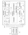
- the touch panel display 16 of the user device 12 displays a reception screen 66 and a virtual viewpoint video screen 68 .
- a reception screen 66 and a virtual viewpoint video screen 68 are displayed side by side on the touch panel display 16 .
- the reception screen 66 and the virtual viewpoint video screen 68 may be switched and displayed in accordance with an instruction given by the user 14 to the touch panel display 16.
- the virtual viewpoint video screen 68 may be individually displayed by a different display device.
- the reception screen 66 is displayed on the touch panel display 16 of the user device 12, but the technology of the present disclosure is not limited to this.
- the reception screen 66 may be displayed on a display connected to a device (for example, workstation and/or personal computer, etc.) used by a person who creates or edits.
- the user device 12 acquires the virtual viewpoint video 78 (see FIG. 8) from the image processing device 10 by communicating with the image processing device 10 .
- a virtual viewpoint video 78 (see FIG. 8) acquired from the image processing apparatus 10 by the user device 12 is displayed on the virtual viewpoint video screen 68 of the touch panel display 16 .
- the virtual viewpoint video 78 is not displayed on the virtual viewpoint video screen 68 .
- the user device 12 acquires reception screen data 70 representing the reception screen 66 from the image processing apparatus 10 by communicating with the image processing apparatus 10 .
- a reception screen 66 indicated by the reception screen data 70 acquired from the image processing apparatus 10 by the user device 12 is displayed on the touch panel display 16 .
- the reception screen 66 includes an overhead video screen 66A, a guide message display area 66B, an enter key 66C, and a cancel key 66D, and displays various information necessary for generating the virtual viewpoint video 78 (see FIG. 8). be.
- the user 14 gives an instruction to the user device 12 with reference to the reception screen 66 .
- An instruction from the user 14 is received by the touch panel display 16, for example.
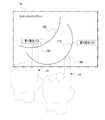
- a bird's-eye view image 72 is displayed on the bird's-eye view image screen 66A.
- the bird's-eye view image 72 is a moving image showing a situation when the inside of the soccer stadium is viewed from above, and is based on a plurality of captured images 64 obtained by being captured by at least one of the plurality of imaging devices 36. generated. Examples of the bird's-eye view video 72 include recorded video and/or live broadcast video.
- the operation requested by the user 14 refers to, for example, an operation (for example, an operation of setting a viewpoint, an operation of setting a gaze point, etc.) necessary for generating the virtual viewpoint video 78 (see FIG. 8).
- the display contents of the guidance message display area 66B are switched according to the operation mode of the user device 12.
- the user device 12 has, as operation modes, a viewpoint setting mode for setting a viewpoint and a gaze point setting mode for setting a gaze point.
- the display contents of the guidance message display area 66B are different.
- Both the enter key 66C and the cancel key 66D are soft keys.
- the decision key 66C is turned on by the user 14 when deciding the instruction accepted by the acceptance screen 66 .
- the cancel key 66D is turned on by the user 14 when canceling the instruction accepted by the acceptance screen 66.
- the reception screen generation unit 28A acquires multiple captured images 64 from multiple imaging devices 36 .
- the captured image 64 includes imaging condition information 64A.
- the imaging condition information 64A refers to information indicating imaging conditions. Examples of imaging conditions include three-dimensional coordinates that can specify the installation position of the imaging device 36, the imaging direction of the imaging device 36, the angle of view used in imaging by the imaging device 36, and the zoom magnification etc.
- the reception screen generation unit 28A generates a bird's-eye view image 72 based on a plurality of captured images 64 acquired from a plurality of imaging devices 36. Then, the reception screen generation unit 28A generates data representing the reception screen 66 including the bird's-eye view image 72 as the reception screen data 70 .
- the reception screen generation unit 28A outputs the reception screen data 70 to the transmission/reception device 24.
- the transmitting/receiving device 24 transmits the reception screen data 70 input from the reception screen generator 28A to the user device 12 .
- the user device 12 receives the reception screen data 70 transmitted from the transmission/reception device 24 by the transmission/reception device 44 (see FIG. 2).
- a reception screen 66 indicated by the reception screen data 70 received by the transmitting/receiving device 44 is displayed on the touch panel display 16 .
- a message 66B1 is displayed in the guidance message display area 66B of the reception screen 66.
- the message 66B1 is a message prompting the user 14 to specify a viewpoint used for generating the virtual viewpoint video 78 (see FIG. 8).
- the viewpoint refers to a virtual viewpoint from which the inside of the soccer stadium is observed.
- a virtual viewpoint is not a position where a real camera such as a physical camera (for example, the imaging device 36) that captures an image of a subject is installed, but a position where a virtual camera that captures an image of the subject is installed. Point.
- the touch panel display 16 accepts instructions from the user 14 while the message 66B1 is displayed in the guidance message display area 66B.
- the instruction from the user 14 refers to a viewpoint instruction.
- a viewpoint corresponds to the position of a pixel in the bird's-eye view image 72 .
- the positions of the pixels in the bird's-eye view image 72 correspond to the positions in the soccer stadium.
- the viewpoint is indicated by the user 14 indicating the position of a pixel in the bird's-eye view image 72 via the touch panel display 16 .
- the viewpoint may be three-dimensional coordinates corresponding to a three-dimensional position in the bird's-eye view image 72 . Any method can be used as a method of indicating a three-dimensional position.
- the user 14 may directly input three-dimensional coordinate positions, or two images of a soccer stadium viewed from two planes perpendicular to each other may be displayed, and three-dimensional coordinate positions may be obtained by specifying pixel positions in each image. You can specify the position.
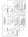
- a viewpoint path P1 which is a path for observing a subject, is shown as an example of a viewpoint.
- the viewpoint path P1 is an assembly in which a plurality of viewpoints are linearly arranged from the start point P1s to the end point P1e.
- the viewpoint path P1 is a path (in the example shown in FIG. to the end point P1e).
- the observation time from the viewpoint path P1 (for example, the time to observe between two different viewpoints and/or the time to observe while standing still at one point) can be obtained via the touch panel display 16 via the viewpoint path P1. It is defined by the speed of sliding performed on the touch panel display 16 when forming, the time of staying at one viewpoint on the viewpoint path P1 (for example, the time of long press), and the like.
- the enter key 66C is turned on to confirm the viewpoint path P1
- the cancel key 66D is turned on to cancel the viewpoint path P1.
- viewpoint path P1 is set in the example shown in FIG. 5, this is merely an example, and a plurality of viewpoint paths may be set.
- viewpoint path is not limited to a plurality of discontinuous viewpoints, or may be one viewpoint.
- a message 66B2 is displayed in the guidance message display area 66B of the reception screen 66.
- the message 66B2 is a message that urges the user 14 to specify the gaze point used for generating the virtual viewpoint video 78 (see FIG. 8).
- the gaze point refers to a point to be virtually gazed at when observing the inside of the soccer stadium from the viewpoint.
- the virtual line-of-sight direction imaging direction of the virtual camera
- the virtual line-of-sight direction refers to the direction from the viewpoint to the gaze point.
- the touch panel display 16 accepts instructions from the user 14 while the message 66B2 is displayed in the guidance message display area 66B.
- the instruction from the user 14 refers to the instruction of the gaze point.
- the gaze point corresponds to the position of a pixel in the bird's-eye view image 72 .
- the positions of the pixels in the bird's-eye view image 72 correspond to the positions in the soccer stadium.
- the gaze point is indicated by the user 14 indicating the position of a pixel in the bird's-eye view image 72 via the touch panel display 16 . In the example shown in FIG. 6, the gaze point GP is shown.
- the gaze point GP is defined according to the point where the user 14 touches the fingertip 14A on the area corresponding to the display area of the bird's-eye view image 72 out of the entire area of the touch panel display 16 .
- the enter key 66C is turned on to confirm the point of gaze GP
- the cancel key 66D is turned on to cancel the point of gaze GP.
- the gaze point may be three-dimensional coordinates corresponding to a three-dimensional position in the bird's-eye view image 72 .
- An arbitrary technique can be used as a method of indicating the three-dimensional position, as in the case of indicating the position of the viewpoint.
- the gazing point GP is designated, but this is merely an example, and a plurality of gazing points may be specified, or a plurality of gazing points may be arranged linearly. It may be a path ( gaze point path). There may be one gaze point path or a plurality of gaze point paths.
- the processor 52 of the user device 12 generates a plurality of pieces of viewpoint information 74 based on the viewpoint path P1 and the gaze point GP.
- the multiple viewpoint information 74 is an example of "multiple viewpoint information" according to the technology of the present disclosure.
- the viewpoint information 74 is information used for generating the virtual viewpoint video 78 (see FIG. 8).
- the viewpoint information 74 includes viewpoint position information 74A, line-of-sight direction information 74B, angle of view information 74C, movement speed information 74D, and elapsed time information 74E.
- the viewpoint position information 74A is information that can specify the position of the viewpoint (hereinafter also referred to as "viewpoint position").
- the viewpoint position refers to, for example, the position of the virtual camera described above.
- the viewpoint position the position of a pixel in the bird's-eye view image 72 of one viewpoint included in the viewpoint path P1 (see FIG. 5) determined in the viewpoint setting mode is applied.
- An example of the information specifying the position of the pixel within the bird's-eye view image 72 of the viewpoint path P1 is the coordinates for specifying the position of the pixel of the viewpoint path P1 within the bird's-eye view image 72 .
- the viewpoint path P1 includes a start point P1s and an end point P1e (see FIG. 5). Therefore, the plurality of viewpoint position information 74A indicating all the viewpoints included in the viewpoint path P1 includes start point position information (hereinafter also simply referred to as "start point position information”) that can specify the position of the start point P1s, and the end point P1e. It also includes end point position information (hereinafter simply referred to as "end point position information”) that can specify the position.
- start point position information is coordinates that can specify the position of the pixel of the starting point P1s in the bird's-eye view image 72 .
- An example of the end point position information is coordinates that can identify the pixel position of the end point P1e in the bird's-eye view image 72 .
- the line-of-sight direction information 74B is information that can specify the line-of-sight direction.
- the line-of-sight direction refers to, for example, the direction in which the subject is observed from the viewpoint included in the viewpoint path P1 toward the gaze point GP.
- the line-of-sight direction information 74B is determined, for example, for each viewpoint specified from a plurality of viewpoint position information 74A indicating all viewpoints included in the viewpoint path P1. 72), and information capable of specifying the position of the gaze point GP determined in the gaze point setting mode (for example, the pixel position of the gaze point GP in the bird's-eye view image 72). coordinates that specify the
- the angle-of-view information 74C is information indicating the angle of view (hereinafter also simply referred to as "angle of view").
- the angle of view refers to the viewing angle at which the subject is observed on the viewpoint path P1.
- the angle of view is fixed at a predetermined angle (eg, 100 degrees).
- the angle of view may be determined according to the moving speed.
- the movement speed refers to the speed at which the viewpoint position for observing the subject moves on the viewpoint path P1.
- An example of the moving speed is the speed of sliding performed on the touch panel display 16 when forming the viewpoint path P1 via the touch panel display 16 .
- the angle of view is determined according to the moving speed, for example, within a range in which the upper limit (for example, 150 degrees) and the lower limit (for example, 15 degrees) of the angle of view are defined, the lower the moving speed, the narrower the angle of view. Become. Also, the angle of view may be narrowed as the moving speed increases.
- the angle of view may be determined according to the elapsed time corresponding to the viewpoint position (hereinafter also simply referred to as "elapsed time").
- the elapsed time indicates, for example, the time during which the viewpoint remains stationary at a viewpoint position on the viewpoint path P1.
- the angle of view is determined according to the elapsed time, for example, when the elapsed time exceeds a first predetermined time (for example, 3 seconds), the angle of view is minimized, or when the elapsed time exceeds the first predetermined time The angle of view should be maximized.
- a first predetermined time for example, 3 seconds
- the angle of view may be determined according to an instruction received by the receiving device 50.
- the receiving device 50 may receive an instruction regarding the viewpoint position at which the angle of view is to be changed on the viewpoint path P1 and the angle of view after the change.
- the moving speed information 74D is information indicating the above-described moving speed (hereinafter also simply referred to as "moving speed"), and is associated with each corresponding viewpoint within the viewpoint path P1.
- the elapsed time information 74E is information indicating elapsed time.
- the processor 52 outputs a plurality of pieces of viewpoint information 74 to the transmission/reception device 44 .
- the transmitting/receiving device 44 transmits a plurality of pieces of viewpoint information 74 input from the processor 52 to the image processing device 10 .
- the transmitting/receiving device 24 of the image processing device 10 receives a plurality of pieces of viewpoint information 74 transmitted from the transmitting/receiving device 44 .
- the virtual viewpoint video generation unit 28B of the image processing device 10 acquires a plurality of pieces of viewpoint information 74 received by the transmission/reception device 24 .
- the virtual viewpoint video generation unit 28B generates a virtual viewpoint image 76 according to a plurality of viewpoint information 74 (for example, a plurality of viewpoint information 74 capable of specifying the viewpoint path P1 shown in FIG. 5).
- a plurality of picked-up images 64 (see FIG. 4) to be used for are selected. That is, the virtual viewpoint video generation unit 28B generates a plurality of captured images 64 (see FIG. 4) used for generating a virtual viewpoint image 76, which is an image showing the state of the subject when the subject is observed according to the plurality of viewpoint information 74. Selection is made from a plurality of captured images 64 obtained by being captured by a plurality of imaging devices 36 (see FIGS. 1 and 4).
- the virtual viewpoint video generation unit 28B generates a virtual viewpoint video 78 based on multiple pieces of viewpoint information 74 and multiple captured images 64 . That is, the virtual viewpoint video generation unit 28B generates a plurality of viewpoint information 74 (for example, a plurality of viewpoint information capable of specifying a viewpoint path P1 shown in FIG. 5) based on a plurality of captured images 64 selected according to a plurality of viewpoint information 74. 74) generates a virtual viewpoint video 78 which is a video showing the state of the subject when the subject is observed from the viewpoint specified by 74).
- viewpoint information 74 for example, a plurality of viewpoint information capable of specifying a viewpoint path P1 shown in FIG. 5
- the virtual viewpoint video generation unit 28B generates a virtual viewpoint image 76 of multiple frames according to the viewpoint path P1 (see FIG. 5). That is, the virtual viewpoint video generation unit 28B generates a virtual viewpoint image 76 for each viewpoint on the viewpoint path P1.
- the virtual viewpoint video generation unit 28B generates a virtual viewpoint video 78 by arranging a plurality of frames of virtual viewpoint images 76 in time series.
- the virtual viewpoint video 78 generated in this manner is data for displaying on the touch panel display 16 of the user device 12 .
- the time during which the virtual viewpoint moving image 78 is displayed on the touch panel display 16 is determined according to the plurality of viewpoint information 74 (for example, the plurality of viewpoint information 74 indicating the viewpoint path P1 shown in FIG. 1).
- the virtual viewpoint video generation unit 28B provides metadata 76A to each of the multiple frames of the virtual viewpoint images 76 included in the virtual viewpoint video 78 .
- the metadata 76A is generated by the virtual viewpoint video generation unit 28B based on the imaging condition information 64A (see FIG. 4) included in the captured image 64 used to generate the virtual viewpoint image 76, for example.
- the metadata 76A includes information based on the time when the virtual viewpoint image 76 was generated and the imaging condition information 64A.
- the virtual viewpoint video generation unit 28B gives the video identification information 80 to the virtual viewpoint video 78 each time it generates the virtual viewpoint video 78 .
- the moving image identification information 80 includes an identifier uniquely assigned to the virtual viewpoint moving image 78 and is used to identify the virtual viewpoint moving image 78 .
- the moving image identification information 80 also includes metadata such as the time when the virtual viewpoint moving image 78 was generated and/or the total playback time of the virtual viewpoint moving image 78 .
- the virtual viewpoint video generation unit 28B stores the generated virtual viewpoint video 78 in the storage 30.
- the storage 30 stores, for example, virtual viewpoint videos 78 generated by the virtual viewpoint video generation unit 28B for a plurality of viewpoint paths including the viewpoint path P1.
- the acquisition unit 28C is used by the virtual viewpoint video generation unit 28B to generate a virtual viewpoint video 78 (in the example shown in FIG. 9, the virtual viewpoint video 78 stored in the storage 30).
- a plurality of pieces of viewpoint information 74 are acquired from the virtual viewpoint video generation unit 28B.
- the acquisition unit 28C acquires the specific section virtual viewpoint video 78A from the virtual viewpoint videos 78 stored in the storage 30 .
- the specific section virtual viewpoint video 78A is a time zone in which the viewpoint position, line-of-sight direction, and angle of view in the virtual viewpoint video 78 are fixed (for example, a viewpoint in a plurality of viewpoint positions included in the viewpoint path P1 is stationary).
- 74E indicates a virtual viewpoint video generated by the virtual viewpoint video generation unit 28B according to the viewpoint information 74 (that is, a plurality of frames of virtual viewpoint images).
- the extraction unit 28D identifies the target subject 81 determined based on the time included in the virtual viewpoint video 78 (in the example shown in FIG. 9, the time zone in which the viewpoint position, line-of-sight direction, and angle of view are fixed).
- the target subject 81 is an example of the "first subject" according to the technology of the present disclosure.
- a first example of the time included in the virtual viewpoint video 78 is the length of time the subject is shown.
- a second example of the time included in the virtual viewpoint video 78 is the first and/or last time period (for example, several seconds) of the total playback time of the virtual viewpoint video 78 .
- a third example of the time included in the virtual viewpoint video 78 is a point in time.
- the extraction unit 28D performs AI-based subject recognition processing on all virtual viewpoint images 76 included in the specific section virtual viewpoint video 78A acquired by the acquisition unit 28C, so that the specific section The subject that appears the longest in the virtual viewpoint video 78A is specified as the target subject 81.
- the extraction unit 28D extracts a plurality of frames of virtual viewpoint images 76 including the identified target subject 81 from the specific section virtual viewpoint video 78A.
- an identifier for identifying a subject (hereinafter referred to as a "subject identifier") is assigned in advance to each subject included in all the virtual viewpoint images 76 included in the virtual viewpoint video 78. 28D may identify the subject included in each virtual viewpoint image 76 by referring to the subject identifier.
- the selection unit 28E selects one frame of the virtual viewpoint image 76 determined based on the size of the target subject 81 in the multiple frames of the virtual viewpoint images 76 extracted by the extraction unit 28D. For example, the selection unit 28E selects one frame of the virtual viewpoint image 76 including the target subject 81 of the maximum size from the multiple frames of the virtual viewpoint images 76 extracted by the extraction unit 28D. For example, when the AI-based subject recognition process is performed by the extracting unit 28D, the selecting unit 28E refers to the size of the bounding box used in the AI-based subject recognition process to determine whether the target subject 81 of the maximum size is included. A virtual viewpoint image 76 is specified.
- the plurality of frames extracted by the extraction unit 28D is an example of "a plurality of frames including the first subject within the imaging region in the virtual viewpoint video" according to the technology of the present disclosure.
- the one-frame virtual viewpoint image 76 including the target subject 81 of the maximum size is an example of the "image related to the first frame” according to the technology of the present disclosure.
- the "maximum size” is an example of the "first subject size” according to the technology of the present disclosure.
- the target subject 81 of the maximum size is illustrated here, this is merely an example, and the target subject 81 of a specified size other than the maximum size (for example, the next largest size after the maximum size) or the maximum size of the target subject 81 within a predetermined size range (for example, a size range determined according to an instruction received by the reception device 50 or the like).
- the target subject 81 may have a size determined according to an instruction received by the device 50 or the like.
- the processing unit 28F processes the virtual viewpoint video 78 into an image with a size different from that of the virtual viewpoint video 78.
- the image having a size different from that of the virtual viewpoint video 78 includes, for example, an image with a smaller amount of data than the virtual viewpoint video 78 (for example, an image of at least one frame), and an image obtained by thinning the virtual viewpoint video 78 (for example, , frame-by-frame images), an image obtained by reducing the display size of at least one frame of the virtual viewpoint image 76 included in the virtual viewpoint video 78, and/or at least one frame of the virtual viewpoint image 76 included in the virtual viewpoint video 78.
- an image obtained by thinning out the pixels in the image for example, an image obtained by thinning out the pixels in the image.
- the processing unit 28F generates an image related to one frame of the virtual viewpoint image 76 out of all the virtual viewpoint images 76 included in the virtual viewpoint video 78 .
- the image related to the one-frame virtual viewpoint image 76 is, for example, an image showing the content of the virtual viewpoint video 78 .
- the image related to the one-frame virtual viewpoint image 76 is an example of the "image related to the first frame" according to the technology of the present disclosure.
- the image related to the one-frame virtual viewpoint image 76 for example, the entire one-frame virtual viewpoint image 76 itself, a part cut out from the one-frame virtual viewpoint image 76, and/or the one-frame virtual viewpoint image 76. Examples include processed images.
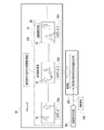
- the processing unit 28F acquires a thumbnail image 82 corresponding to the virtual viewpoint video 78 based on the plurality of captured images 64 and the plurality of viewpoint information 74.
- the thumbnail image 82 is an example of a "representative image" according to the technology of the present disclosure. That is, the processing unit 28 ⁇ /b>F thumbnails a representative one-frame virtual viewpoint image 76 of all the virtual viewpoint images 76 included in the virtual viewpoint video 78 . For example, the processing unit 28F processes the virtual viewpoint image 76 selected by the selection unit 28E into the thumbnail image 82.
- a method of processing the virtual viewpoint image 76 into the thumbnail image 82 As a method of processing the virtual viewpoint image 76 into the thumbnail image 82, a method of processing the virtual viewpoint video 78 into an image having a size different from that of the virtual viewpoint video 78 can be used. Further, the processing unit 28F associates the thumbnail image 82 with the metadata 76A attached to the virtual viewpoint image 76 before thumbnailing. Further, the processing unit 28F acquires the moving image identification information 80 from the virtual viewpoint moving image 78 including the thumbnail virtual viewpoint image 76 .
- the processing unit 28F associates the moving image identification information 80 with the thumbnail image 82 obtained by thumbnailing the virtual viewpoint image 76 .
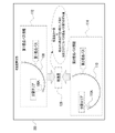
- the list screen generation unit 28G acquires the thumbnail image 82 associated with the metadata 76A and the moving image identification information 80 from the processing unit 28F.
- the list screen generation unit 28G generates reference information 86A based on the metadata 76A and/or the moving image identification information 80, and associates it with the thumbnail image 82.
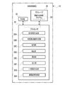
- the list screen generation unit 28G generates list screen data 84 showing a list screen 86 including the thumbnail image 82 associated with the reference information 86A.
- the list screen data 84 is data for displaying the thumbnail images 82 on the touch panel display 16 of the user device 12 .
- the list screen generation unit 28G outputs the generated list screen data 84 to the transmission/reception device 24 and causes the storage 30 to store it.
- the thumbnail image 82 associated with the moving image identification information 80 is stored in the storage 30 . That is, since the moving image identification information 80 is an identifier uniquely assigned to the virtual viewpoint moving image 78, the thumbnail image 82 and the virtual viewpoint moving image 78 are stored in the storage 30 in a state of being associated with each other.
- the list screen data 84 is an example of "data” and “first data” according to the technology of the present disclosure.
- the touch panel display 16 is an example of the “display” and the “first display” according to the technology of the present disclosure.
- the reference information 86A associated with the thumbnail image 82 by the list screen generation unit 28G includes, for example, character information.
- the text information includes, for example, the time when the virtual viewpoint video 78 was generated (for example, the time specified from the imaging condition information 64A shown in FIG. 4), information related to the target subject 81 included in the thumbnail image 82 (for example, the name of the target subject 81 and/or the team to which the target subject 81 belongs, etc.), the total playback time of the virtual viewpoint video 78, the title of the virtual viewpoint video 78, and/or the name of the creator of the virtual viewpoint video 78, etc. character information indicating
- the list screen generation unit 28G acquires the list screen data 84 from the storage 30 and updates the list screen data 84 . That is, the list screen generation unit 28G acquires the thumbnail image 82 associated with the metadata 76A and the moving image identification information 80 from the processing unit 28F, and generates reference information 86A. List screen generator 28G associates generated reference information 86A with thumbnail image 82 . Then, the list screen generation unit 28G updates the list screen data 84 by including in the list screen 86 the thumbnail image 82 associated with the reference information 86A. The list screen generation unit 28G outputs the updated list screen data 84 to the transmission/reception device 24 and causes the storage 30 to store it.
- a list screen 86 indicated by the updated list screen data 84 includes a plurality of thumbnail images 82 . Further, in the list screen 86 indicated by the updated list screen data 84, each of the plurality of thumbnail images 82 is associated with reference information 86A.
- the transmitting/receiving device 24 transmits to the user device 12 the list screen data 84 input from the list screen generation unit 28G.
- the transmission/reception device 44 receives the list screen data 84 transmitted from the image processing device 10 .
- the processor 52 acquires the list screen data 84 received by the transmitter/receiver 44 and causes the touch panel display 16 to display the list screen 86 indicated by the acquired list screen data 84 .
- a plurality of images are displayed in parallel on the list screen 86 .
- a list screen 86 displays a plurality of thumbnail images 82 together with reference information 86A.
- the reference information 86A is arranged in such a manner that the relationship with the thumbnail image 82 can be visually grasped (for example, the reference information 86A and the thumbnail image 82 are aligned so that the one-to-one relationship can be visually grasped). displayed on the list screen 86 in the form shown in FIG.
- thumbnail images 82 are displayed on the list screen 86 , but only one thumbnail image 82 may be displayed on the list screen 86 .
- the plurality of thumbnail images 82 do not necessarily have to be displayed in parallel, and any form of display may be used as long as the plurality of thumbnail images 82 can be visually grasped.
- the user 14 taps any thumbnail image 82 in the list screen 86 via the touch panel display 16 to select the thumbnail image 82 .
- the processor 28 (see FIGS. 1 and 3) of the image processing device 10 transmits data for displaying the virtual viewpoint video 78 on the touch panel display 16 to the user device. output to 12.
- processor 52 of user device 12 transmits animation identification information 80 associated with selected thumbnail image 82 via transceiver 44 . and transmits it to the image processing apparatus 10 .
- the moving image identification information 80 is received by the transmission/reception device 24 .
- the processor 28 (see FIGS. 1 and 3) of the image processing device 10 acquires the virtual viewpoint video 78 corresponding to the video identification information 80 received by the transmission/reception device 24 from the storage 30, and stores the acquired virtual viewpoint video 78. , to the user device 12 via the transceiver 24 .
- the transmitting/receiving device 44 receives the virtual viewpoint video 78 transmitted from the image processing device 10 .
- the processor 52 of the user device 12 causes the touch panel display 16 to display the virtual viewpoint video 78 received by the transceiver 44 .
- the virtual viewpoint video 78 is displayed on the virtual viewpoint video screen 68 (see FIG. 4) of the touch panel display 16 .
- the virtual viewpoint video 78 may be displayed on a display that is directly or indirectly connected to the image processing device 10 .
- the display directly or indirectly connected to the image processing device 10 is an example of the "second display" according to the technology of the present disclosure.
- thumbnail image 82 is selected by tapping any thumbnail image 82 in the list screen 86 , but this is merely an example, and the touch panel display 16
- the thumbnail image 82 may be selected by flicking, swiping, and/or long-pressing the thumbnail image 82 via the .
- the thumbnail image 82 may be selected by performing the operation, or the thumbnail image 82 may be selected by operating a mouse and/or keyboard.
- FIG. 11 shows an example of the flow of screen generation processing performed by the processor 28 of the image processing device 10 .
- the flow of screen generation processing shown in FIG. 11 is an example of an image processing method according to the technology of the present disclosure.
- step ST10 the virtual viewpoint video generation unit 28B acquires a plurality of viewpoint information 74 (for example, a plurality of viewpoint information 74 corresponding to the viewpoint path P1) from the user device 12. (See FIG. 7). After the process of step ST10 is executed, the screen generation process proceeds to step ST12.
- a plurality of viewpoint information 74 for example, a plurality of viewpoint information 74 corresponding to the viewpoint path P1
- step ST12 the virtual viewpoint video generation unit 28B selects a plurality of captured images 64 according to the plurality of viewpoint information 74 acquired at step ST10 (see FIG. 8). After the process of step ST12 is executed, the screen generation process proceeds to step ST14.
- step ST14 the virtual viewpoint video generation unit 28B generates a virtual viewpoint video 78 based on the plurality of captured images 64 selected in step ST12, and stores the generated virtual viewpoint video 78 in the storage 30 (see FIG. 8). .
- step ST14 the screen generation process proceeds to step ST16.
- step ST16 the acquisition unit 28C determines the viewpoint position, line-of-sight direction, and angle of view in the virtual viewpoint video 78 according to the plurality of viewpoint information 74 used in the generation of the virtual viewpoint video 78 by the virtual viewpoint video generation unit 28B.
- a virtual viewpoint video in a fixed time period is acquired from the storage 30 as a specific section virtual viewpoint video 78A (see FIG. 9).
- step ST18 the extraction unit 28D performs AI-based subject recognition processing on the specific section virtual viewpoint video 78A, thereby obtaining a plurality of images including the target subject 81 that appears the longest in the specific section virtual viewpoint video 78A.
- virtual viewpoint image 76 is extracted from the specific section virtual viewpoint video 78A (see FIG. 9).
- step ST20 the selection unit 28E selects the virtual viewpoint image 76 including the target subject 81 of the maximum size from the plurality of virtual viewpoint images 76 extracted at step ST18 (see FIG. 9). After the process of step ST20 is executed, the screen generation process proceeds to step ST22.
- step ST22 the processing unit 28F processes the virtual viewpoint image 76 selected at step ST20 into the thumbnail image 82 (see FIGS. 9 and 10). Metadata 76A of the virtual viewpoint image 76 selected in step ST20 is added to the thumbnail image 82 by the processing unit 28F. After the process of step ST22 is executed, the screen generation process proceeds to step ST24.
- step ST24 the processing unit 28F acquires from the storage 30 the video identification information 80 related to the virtual viewpoint video 78 including the virtual viewpoint image 76 corresponding to the thumbnail image 82 obtained in step ST22 (see FIG. 9), and acquires the video identification information 80.
- the obtained moving image identification information 80 is associated with the thumbnail image 82 (see FIG. 10).
- step ST26 the list screen generation unit 28G generates list screen data 84 showing a list screen 86 including the thumbnail image 82 associated with the metadata 76A and the moving image identification information 80, and stores the generated list screen data 84 in the storage 30. and output to the transmitting/receiving device 24 (see FIG. 10).
- the list screen data 84 is stored in the storage 30 , and the list screen data 84 is transmitted to the user device 12 by the transmitting/receiving device 24 .
- the list screen 86 indicated by the list screen data 84 transmitted from the transmitter/receiver 24 is displayed on the touch panel display 16 by the processor 52 (see FIG. 10).
- the list screen generation unit 28G determines whether or not a condition for terminating the screen generation process (hereinafter referred to as "end condition") is satisfied.
- An example of the termination condition is that an instruction to terminate the screen generation process has been received by the receiving device such as the touch panel display 16 or the like.
- the termination condition is not satisfied, the determination is negative, and the screen generation process proceeds to step ST10.
- the termination condition is satisfied, the determination is affirmative, and the screen generation process is terminated.
- the thumbnail images 82 corresponding to the virtual viewpoint moving images 78 generated based on the plurality of captured images 64 and the plurality of viewpoint information 74 are displayed in a plurality of It is acquired based on the captured image 64 and a plurality of pieces of viewpoint information 74 .
- List screen data 84 is transmitted to the user device 12 as data for displaying the thumbnail images 82 on the touch panel display 16 of the user device 12 .
- a list screen 86 indicated by the list screen data 84 is displayed on the touch panel display 16 . Therefore, according to this configuration, it is possible to contribute to showing the thumbnail image 82 corresponding to the virtual viewpoint video 78 to the user 14 .
- the specific section virtual viewpoint video 78A included in the virtual viewpoint video 78 is acquired. Then, the thumbnail image 82 corresponding to one frame of the virtual viewpoint image 76 among the plurality of frames of the virtual viewpoint image 76 included in the specific section virtual viewpoint video 78A is obtained.
- List screen data 84 is transmitted to the user device 12 as data for displaying the thumbnail images 82 on the touch panel display 16 of the user device 12 . Therefore, according to this configuration, it contributes to showing the user 14 the thumbnail image 82 corresponding to one frame of the virtual viewpoint image 76 among the plurality of frames of the virtual viewpoint image 76 included in the specific section virtual viewpoint video 78A. can be done.
- the thumbnail image 82 corresponding to the one-frame virtual viewpoint image 76 including the target subject 81 determined based on the time included in the virtual viewpoint moving image 78 is displayed. is obtained.
- List screen data 84 is transmitted to the user device 12 as data for displaying the thumbnail images 82 on the touch panel display 16 of the user device 12 . Therefore, according to this configuration, the thumbnail image 82 corresponding to one frame of the virtual viewpoint image 76 including the target subject 81 determined based on the time included in the virtual viewpoint moving image 78 is shown to the user 14 . can contribute.
- a thumbnail image 82 corresponding to one frame of the virtual viewpoint image 76 determined based on the size of the target subject 81 in the specific section virtual viewpoint video 78A is obtained. be done.
- List screen data 84 is transmitted to the user device 12 as data for displaying the thumbnail images 82 on the touch panel display 16 of the user device 12 . Therefore, according to this configuration, it is possible to contribute to showing the user 14 the thumbnail image 82 corresponding to one frame of the virtual viewpoint image 76 determined based on the size of the target subject 81 .
- the virtual viewpoint video 78 corresponding to the selected thumbnail image 82 is displayed on the touch panel.
- List screen data 84 is transmitted to the user device 12 as data to be displayed on the display 16 . Therefore, according to this configuration, it is possible to contribute to allowing the user 14 to view the virtual viewpoint video 78 corresponding to the selected thumbnail image 82 .
- the thumbnail image 82 and the virtual viewpoint video 78 are stored in the storage 30 in a state of being associated with each other. Therefore, according to this configuration, the virtual viewpoint video 78 can be obtained from the thumbnail image 82 more quickly than when the thumbnail image 82 and the virtual viewpoint video 78 are not associated.
- data for displaying the thumbnail image 82 in the list screen data 84 in which a plurality of images are displayed in parallel is transmitted to the user device 12 as the list screen data 84. be done. Therefore, according to this configuration, it is possible to contribute to allowing the user 14 to list the plurality of images and the thumbnail images 82 .
- the virtual viewpoint video in the time period in which the viewpoint position, line-of-sight direction, and angle of view are fixed is the specific section virtual viewpoint video 78A, but the technology of the present disclosure is not limited to this.
- a virtual viewpoint video in a time zone specified by the user 14 or the like may be the specific section virtual viewpoint video 78A, or among the plurality of viewpoint information 74, the moving speed within a predetermined speed range may be set.
- a virtual viewpoint video specified from at least one viewpoint information 74 having movement speed information 74D indicating a may be a specific section virtual viewpoint video 78A, or a specific viewpoint position, a specific line-of-sight direction, and/or a specific angle of view
- a virtual viewpoint video specified from at least one piece of viewpoint information 74 corresponding to may be used as the specific section virtual viewpoint video 78A.
- the processor 28 of the image processing apparatus 10 executes a screen generation processing program 38 as an editing result acquisition unit 28H, compared to the processor 28 shown in FIG. They are different in that they also operate.
- the viewpoint path P1 is edited by receiving an instruction from the user 14 on the touch panel display 16 .
- the start point P1s and the end point P1e are common before and after the viewpoint path P1 is edited, and the paths from the start point P1s to the end point P1e are different.
- the processor 52 converts the plurality of viewpoint information 74 described in the first embodiment, that is, the plurality of viewpoint information 74 related to the pre-editing viewpoint path P1 to the pre-editing viewpoint.
- the path information 88 is transmitted to the image processing apparatus 10 via the transmission/reception device 44 .
- the processor 52 also generates post-editing viewpoint path information 90 based on the post-editing viewpoint path P1 and the gaze point GP (see FIG. 6).
- the post-editing viewpoint path information 90 has a plurality of pieces of viewpoint information 74 regarding the post-editing viewpoint path P1.
- the processor 52 generates post-editing viewpoint path information 90 in response to the editing of the viewpoint path P1, and transmits the generated post-editing viewpoint path information 90 to the image processing device 10 via the transmission/reception device 44 .
- the virtual viewpoint video generation unit 28B selects a plurality of captured images 64 (see FIG. 4) to be used for generating a virtual viewpoint image 92 according to post-editing viewpoint path information 90 (see FIG. 14). do. That is, the virtual viewpoint video generating unit 28B generates a plurality of captured images 64 (see FIG. 4) used for generating a virtual viewpoint image 92, which is an image showing the state of the subject when the subject is observed according to the post-editing viewpoint path information 90. , from a plurality of captured images 64 (see FIG. 4) obtained by being captured by a plurality of imaging devices 36 (see FIGS. 1 and 4).
- the virtual viewpoint video generation unit 28B generates a virtual viewpoint video 94 based on the post-editing viewpoint path information 90 and the plurality of captured images 64 . That is, the virtual viewpoint video generation unit 28B can specify post-editing viewpoint path information 90 (for example, post-editing viewpoint path P1 shown in FIG. 13) based on a plurality of captured images 64 selected according to post-editing viewpoint path information 90.
- a virtual viewpoint video 94 which is a video showing the state of the subject when the subject is observed from the viewpoints specified by the plurality of viewpoint information 74), is generated.
- the virtual viewpoint video generation unit 28B generates a virtual viewpoint image 92 of multiple frames according to the edited viewpoint path P1 shown in FIG. That is, the virtual viewpoint video generation unit 28B generates a virtual viewpoint image 92 for each viewpoint on the edited viewpoint path P1.
- the virtual viewpoint video generation unit 28B generates a virtual viewpoint video 94 by arranging a plurality of frames of virtual viewpoint images 92 in time series.
- the virtual viewpoint video 94 generated in this manner is data for displaying on the touch panel display 16 of the user device 12 .
- the time during which the virtual viewpoint video 94 is displayed on the touch panel display 16 is determined by the plurality of viewpoint information 74 included in the post-editing viewpoint path information 90 (for example, the plurality of viewpoint information 74 indicating the post-editing viewpoint path P1 shown in FIG. 13). determined according to
- the virtual viewpoint video generation unit 28B provides metadata 92A to each of the multiple frames of the virtual viewpoint images 92 included in the virtual viewpoint video 94 .
- the metadata 92A is generated by the virtual viewpoint video generation unit 28B based on the imaging condition information 64A (see FIG. 4) included in the captured image 64 used to generate the virtual viewpoint image 92, for example.
- the metadata 92A includes information based on the time when the virtual viewpoint image 92 was generated and the imaging condition information 64A.
- the virtual viewpoint video generation unit 28B gives the video identification information 96 to the virtual viewpoint video 94 each time it generates the virtual viewpoint video 94 .
- the moving image identification information 96 includes an identifier uniquely assigned to the virtual viewpoint moving image 94 and is used to identify the virtual viewpoint moving image 94 .
- the moving image identification information 96 also includes metadata such as the time when the virtual viewpoint moving image 94 was generated and/or the total playback time of the virtual viewpoint moving image 94 .
- the virtual viewpoint video generation unit 28B stores the generated virtual viewpoint video 94 in the storage 30.
- the storage 30 stores, for example, virtual viewpoint videos 94 generated by the virtual viewpoint video generation unit 28B for a plurality of viewpoint paths including the viewpoint path P1 after editing.
- the editing result acquisition unit 28H refers to the pre-editing viewpoint path information 88 and the post-editing viewpoint path information 90 to acquire an editing result 98 that is the result of editing the viewpoint path P1.
- a first example of the editing result 98 is the edited portion of the viewpoint path P1 (hereinafter also referred to as the “edited portion”).
- the edited portion is, for example, at least one piece of viewpoint position information that does not match the plurality of pieces of viewpoint position information 74A included in the pre-editing viewpoint path information 88 among the plurality of pieces of viewpoint position information 74A included in the post-editing viewpoint path information 90. 74A.
- a second example of the editing result 98 is a portion (hereinafter also referred to as “highly edited portion”) where the frequency of editing for the viewpoint path P1 is higher than the predetermined frequency (eg, 3 times).
- the frequently edited portion is specified, for example, from at least one piece of viewpoint position information 74A whose editing frequency exceeds the predetermined frequency among the plurality of pieces of viewpoint position information 74A included in the post-editing viewpoint path information 90 .
- a third example of the editing result 98 is a portion of the post-editing viewpoint path P1 that has a large difference from the pre-editing viewpoint path P1 (hereinafter also referred to as a “difference portion”).
- the difference portion is, for example, a predetermined distance (for example, overhead view image tens of pixels in 72) or more, at least one viewpoint position information 74A.
- the obtaining unit 28C obtains the editing result 98 from the editing result obtaining unit 28H.
- the acquisition unit 28C acquires the specific section virtual viewpoint video 94A from the virtual viewpoint videos 94 stored in the storage 30 .
- the specific section virtual viewpoint video 94A is a virtual viewpoint video of a time zone (for example, an edited part, a frequently edited part, or a differential part) specified from the editing result 98 acquired by the acquisition unit 28C in the virtual viewpoint video 94. is.
- the extraction unit 28D identifies the target subject 100 determined based on the time included in the virtual viewpoint video 94 (in the example shown in FIG. 17, the time zone identified from the editing result 98).
- the target subject 100 is an example of the "first subject" according to the technology of the present disclosure.
- the time included in the virtual viewpoint video 94 includes, for example, the length of time the subject is shown, the first and/or last time zone (for example, several seconds) in the total playback time of the virtual viewpoint video 94, or the point of time. is mentioned.
- the extraction unit 28D performs AI-based subject recognition processing on all virtual viewpoint images 92 included in the specific section virtual viewpoint video 94A acquired by the acquisition unit 28C, so that the specific section The subject that appears the longest in the virtual viewpoint video 94A is specified as the target subject 100. - ⁇ Then, the extraction unit 28D extracts a plurality of frames of virtual viewpoint images 92 including the identified target subject 100 from the specific section virtual viewpoint video 94A.
- an identifier for identifying a subject (hereinafter referred to as a "subject identifier") is assigned in advance to each subject included in all the virtual viewpoint images 92 included in the virtual viewpoint video 94. 28D may identify the subject included in each virtual viewpoint image 92 by referring to the subject identifier.
- the selection unit 28E selects one frame of the virtual viewpoint image 92 determined based on the size of the target subject 100 in the plurality of frames of the virtual viewpoint images 92 extracted by the extraction unit 28D. For example, the selection unit 28E selects one frame of the virtual viewpoint image 92 including the target subject 100 of the maximum size from the plurality of frames of virtual viewpoint images 92 extracted by the extraction unit 28D. For example, when the AI-based subject recognition process is performed by the extracting unit 28D, the selecting unit 28E refers to the size of the bounding box used in the AI-based subject recognition process to determine whether the maximum size of the target subject 100 is included. A virtual viewpoint image 92 is specified.
- the plurality of frames extracted by the extraction unit 28D is an example of "a plurality of frames including the first subject within the imaging region in the virtual viewpoint video" according to the technology of the present disclosure.
- the one-frame virtual viewpoint image 92 including the target subject 100 of the maximum size is an example of the “image related to the first frame” according to the technology of the present disclosure.
- the "maximum size” is an example of the "first subject size” according to the technology of the present disclosure.
- the target subject 100 of the maximum size is illustrated here, this is merely an example, and the target subject 100 of a specified size other than the maximum size (for example, the next largest size after the maximum size) or the maximum size of the target subject 100 within a predetermined size range (for example, a size range determined according to an instruction received by the receiving device 50 or the like).
- the target subject 100 may have a size determined according to an instruction received by the device 50 or the like.
- the processing unit 28F processes the virtual viewpoint video 94 into an image with a size different from that of the virtual viewpoint video 94.
- the image having a size different from that of the virtual viewpoint video 94 includes, for example, an image having a smaller amount of data than the virtual viewpoint video 94 (for example, an image of at least one frame), and an image obtained by thinning the virtual viewpoint video 94 (for example, , frame-by-frame images), an image obtained by reducing the display size of at least one frame of the virtual viewpoint image 92 included in the virtual viewpoint video 94, and/or at least one frame of the virtual viewpoint image 92 included in the virtual viewpoint video 94.
- the processing unit 28F generates an image related to one frame of the virtual viewpoint image 92 among all the virtual viewpoint images 92 included in the virtual viewpoint video 94 .
- the image related to the one-frame virtual viewpoint image 92 is, for example, an image showing the content of the virtual viewpoint video 94 .
- the image related to the one-frame virtual viewpoint image 92 is an example of the "image related to the first frame" according to the technology of the present disclosure.
- the image related to the one-frame virtual viewpoint image 92 for example, the entire one-frame virtual viewpoint image 92 itself, a part cut out from the one-frame virtual viewpoint image 92, and/or the one-frame virtual viewpoint image 92. Examples include processed images.
- the processing unit 28F acquires the thumbnail image 102 corresponding to the virtual viewpoint video 94 based on the plurality of captured images 64 and the plurality of viewpoint information 74. In the second embodiment, the processing unit 28F acquires the thumbnail image 102 based on the editing result 98 corresponding to the result of editing the plurality of viewpoint information 74.
- FIG. The thumbnail image 102 is an example of a “representative image” according to the technology of the present disclosure. That is, the processing unit 28 ⁇ /b>F thumbnails a representative one-frame virtual viewpoint image 92 of all the virtual viewpoint images 92 included in the virtual viewpoint video 94 .
- the processing unit 28F processes the virtual viewpoint image 92 selected by the selection unit 28E into the thumbnail image 102.
- a method of processing the virtual viewpoint image 92 into the thumbnail image 102 a method of processing the virtual viewpoint video 94 into an image having a size different from that of the virtual viewpoint video 94 can be used.
- the processing unit 28F associates the thumbnail image 102 with the metadata 92A added to the virtual viewpoint image 92 before thumbnailing. Further, the processing unit 28F acquires the moving image identification information 96 from the virtual viewpoint moving image 94 including the thumbnailed virtual viewpoint image 92 .
- the processing unit 28F associates the moving image identification information 96 with the thumbnail image 102 obtained by thumbnailing the virtual viewpoint image 92 .
- the list screen generation unit 28G acquires the thumbnail image 102 associated with the metadata 92A and the moving image identification information 96 from the processing unit 28F.
- the list screen generation unit 28G generates reference information 104A based on the metadata 92A and/or the moving image identification information 96 and associates it with the thumbnail image 102.
- FIG. List screen generation unit 28G generates list screen data 106 showing list screen 104 including thumbnail image 102 associated with reference information 104A.
- the list screen data 106 is data for displaying the thumbnail images 102 on the touch panel display 16 of the user device 12 .
- the list screen generation unit 28G outputs the generated list screen data 106 to the transmission/reception device 24 and causes the storage 30 to store it.
- the thumbnail image 102 associated with the moving image identification information 96 is stored in the storage 30 . That is, since the moving image identification information 96 is an identifier uniquely assigned to the virtual viewpoint moving image 94, the thumbnail image 102 and the virtual viewpoint moving image 94 are stored in the storage 30 in a state of being associated with each other.
- the list screen data 106 is an example of “data” and “first data” according to the technology of the present disclosure.
- the reference information 104A associated with the thumbnail image 102 by the list screen generation unit 28G includes, for example, character information.
- the text information includes, for example, the time when the virtual viewpoint video 94 was generated (for example, the time specified from the imaging condition information 64A shown in FIG. 4), information related to the target subject 100 included in the thumbnail image 102 (for example, name of the target subject 100 and/or the team to which the target subject 100 belongs, etc.), the total playing time of the virtual viewpoint video 94, the title of the virtual viewpoint video 94, and/or the name of the creator of the virtual viewpoint video 94, etc. mentioned.
- the list screen generation unit 28G acquires the list screen data 106 from the storage 30 and updates the list screen data 106 . That is, the list screen generation unit 28G acquires the thumbnail image 102 associated with the metadata 92A and the moving image identification information 96 from the processing unit 28F, and generates reference information 104A. List screen generation unit 28G associates generated reference information 104A with thumbnail image 102 .
- the list screen generation unit 28G updates the list screen data 106 by including in the list screen 104 the thumbnail image 102 associated with the reference information 104A.
- the list screen generation unit 28G outputs the updated list screen data 106 to the transmission/reception device 24 and causes the storage 30 to store it.
- a list screen 104 indicated by the updated list screen data 106 includes a plurality of thumbnail images 102 . Further, in the list screen 104 indicated by the updated list screen data 106, each of the plurality of thumbnail images 102 is associated with reference information 104A.
- the transmitting/receiving device 24 transmits to the user device 12 the list screen data 106 input from the list screen generator 28G.
- the transmission/reception device 44 receives the list screen data 106 transmitted from the image processing device 10 .
- the processor 52 acquires the list screen data 106 received by the transmission/reception device 44 and causes the touch panel display 16 to display the list screen 104 indicated by the acquired list screen data 106 .
- a plurality of images are displayed in parallel on the list screen 104 .
- a list screen 104 displays a plurality of thumbnail images 102 together with reference information 104A.
- thumbnail images 102 are displayed on the list screen 104 .
- only one thumbnail image 102 may be displayed on the list screen 104 .
- the plurality of thumbnail images 102 do not necessarily have to be displayed in parallel.
- the user 14 taps any thumbnail image 102 in the list screen 104 via the touch panel display 16 to select the thumbnail image 102 .
- the processor 28 (see FIGS. 1 and 12) of the image processing device 10 transmits data for displaying the virtual viewpoint video 94 on the touch panel display 16 to the user device. output to 12.
- processor 52 of user device 12 transmits animation identification information 96 associated with selected thumbnail image 102 via transmitter/receiver 44 . and transmits it to the image processing apparatus 10 .
- the moving image identification information 96 is received by the transmitting/receiving device 24 .
- the processor 28 (see FIGS. 1 and 12) of the image processing device 10 acquires the virtual viewpoint video 94 corresponding to the video identification information 96 received by the transmission/reception device 24 from the storage 30, and stores the acquired virtual viewpoint video 94. , to the user device 12 via the transceiver 24 .
- the transmitting/receiving device 44 receives the virtual viewpoint video 94 transmitted from the image processing device 10 .
- the processor 52 of the user device 12 causes the touch panel display 16 to display the virtual viewpoint video 94 received by the transceiver 44 .
- the virtual viewpoint video 94 is displayed on the virtual viewpoint video screen 68 of the touch panel display 16 (see FIG. 4).
- the virtual viewpoint video 94 may be displayed on a display that is directly or indirectly connected to the image processing device 10 .
- thumbnail image 102 may be selected by flicking, swiping, and/or long-pressing the thumbnail image 102 via the .
- the thumbnail image 102 may be selected by performing the operation, or the thumbnail image 102 may be selected by using a mouse and/or keyboard.
- the thumbnail image 102 is acquired based on the editing result 98 obtained along with the editing performed on the viewpoint path P1. That is, the thumbnail images 102 corresponding to the virtual viewpoint images 92 specified based on the editing result 98 are acquired from the plurality of virtual viewpoint images 92 included in the virtual viewpoint video 94 .
- a list screen 104 including the thumbnail images 102 acquired by the image processing apparatus 10 is displayed on the touch panel display 16 of the user device 12 . Therefore, according to this configuration, it is possible to contribute to showing the user 14 the thumbnail image 102 obtained based on the editing result 98 .
- the editing result 98 may include not only the viewpoint path P1 but also the results of editing performed on a plurality of viewpoint paths representing a plurality of virtual viewpoint videos.
- the multiple viewpoint information 74 has multiple viewpoint paths. That is, multiple viewpoint paths are defined by multiple viewpoint information 74 .
- the processor 28 generates at least one virtual viewpoint image (that is, at least one virtual viewpoint video obtained from at least one virtual viewpoint video) based on the result of editing performed on at least one viewpoint pass among the plurality of viewpoint passes.
- One virtual viewpoint image is specified.
- the processor 28 generates at least one thumbnail image corresponding to the specified at least one virtual viewpoint image, and generates a list screen 104 including the generated thumbnail images. This can contribute to showing the user 14 at least one thumbnail image corresponding to at least one virtual viewpoint image obtained based on the result of editing performed on a plurality of viewpoint paths.
- the processor 28 of the image processing apparatus 10 executes the screen generation processing program 38 as a dissimilarity calculation unit 28I compared to the processor 28 shown in FIG. They are different in that they also operate.
- a first viewpoint path 108 and a second viewpoint path 110 existing at mutually different positions are selected as viewpoint paths to be processed. is specified by the user 14 via the touch panel display 16. As shown in FIG. 20 as an example, from a plurality of viewpoint paths, a first viewpoint path 108 and a second viewpoint path 110 existing at mutually different positions are selected as viewpoint paths to be processed. is specified by the user 14 via the touch panel display 16. As shown in FIG. 20 as an example, from a plurality of viewpoint paths, a first viewpoint path 108 and a second viewpoint path 110 existing at mutually different positions are selected as viewpoint paths to be processed. is specified by the user 14 via the touch panel display 16. As shown in FIG.
- the processor 52 performs the first viewpoint path 108 (see FIG. 20) based on the first point of regard (eg, the point of regard GP shown in FIG. 6). information 112.
- the first viewpoint path information 112 includes a plurality of viewpoint information 74 described in the first and second embodiments above. 20) and a second gaze point (for example, the gaze point GP shown in FIG. 6), the second viewpoint path information 114 is generated.
- the first viewpoint path information 112 includes a plurality of viewpoint information 74.
- the plurality of viewpoint information 74 included in the first viewpoint path information 112 indicates the characteristics of the first viewpoint path 108
- the plurality of viewpoint information 74 included in the second viewpoint path information 114 indicates the characteristics of the first viewpoint path 108.
- the viewpoint information 74 indicates the characteristics of the second viewpoint path 110. Therefore, the plurality of viewpoint information 74 included in the first viewpoint path information 112, the plurality of viewpoint information 74 included in the second viewpoint path information 114, and the are different in content.
- the processor 52 of the user device 12 transmits the first viewpoint path information 112 and the second viewpoint path information 114 to the image processing device 10 via the transmission/reception device 44 .
- the transmission/reception device 24 receives the first viewpoint path information 112 and the second viewpoint path information 114 transmitted from the image processing device 10 .
- the virtual viewpoint video generation unit 28B and the dissimilarity calculation unit 28I acquire the first viewpoint path information 112 and the second viewpoint path information 114 received by the transmission/reception device 24 .
- the virtual viewpoint video generation unit 28B generates a plurality of captured images 64 (see FIG. 4) used for generating the virtual viewpoint image 116 according to the first viewpoint path information 112 (see FIGS. 21 and 22). ). That is, the virtual viewpoint video generation unit 28B generates a plurality of captured images 64 (see FIG. 4) used for generating the virtual viewpoint image 116, which is an image showing the state of the subject when the subject is observed according to the first viewpoint path information 112. , from a plurality of captured images 64 (see FIG. 4) obtained by being captured by a plurality of imaging devices 36 (see FIGS. 1 and 4).
- the virtual viewpoint video generation unit 28B generates the first virtual viewpoint video 118 based on the first viewpoint path information 112 and the plurality of captured images 64. That is, the virtual viewpoint video generation unit 28B, based on the plurality of captured images 64 selected according to the first viewpoint path information 112, determines the mode of the subject when the subject is observed from the viewpoint specified by the first viewpoint path information 112. A first virtual viewpoint video 118 that is a video shown is generated.
- the virtual viewpoint video generation unit 28B generates a plurality of frames of virtual viewpoint images 116 according to the first viewpoint path 108 (see FIG. 20). That is, the virtual viewpoint video generation unit 28B generates a virtual viewpoint image 116 for each viewpoint on the first viewpoint path 108 .
- the virtual viewpoint video generation unit 28B generates a first virtual viewpoint video 118 by arranging the virtual viewpoint images 116 of multiple frames in time series.
- the first virtual viewpoint video 118 generated in this manner is data to be displayed on the touch panel display 16 of the user device 12 .
- the time during which the first virtual viewpoint moving image 118 is displayed on the touch panel display 16 is determined according to the plurality of viewpoint information 74 (see FIG. 21) included in the first viewpoint path information 112 .
- the virtual viewpoint video generation unit 28B provides first metadata (not shown) to each of the multiple frames of virtual viewpoint images 116 included in the first virtual viewpoint video 118 .
- the technical significance of the first metadata assigned to each of the plurality of frames of the virtual viewpoint images 116 included in the first virtual viewpoint video 118 is the metadata 76A described in the first embodiment and the metadata 76A described in the second embodiment. It is the same as the metadata 92A described in the form.
- the virtual viewpoint video generation unit 28B assigns the first video identification information 120 to the first virtual viewpoint video 118 each time the first virtual viewpoint video 118 is generated.
- the first moving image identification information 120 includes an identifier uniquely assigned to the first virtual viewpoint moving image 118 and is used to identify the first virtual viewpoint moving image 118 .
- the first moving image identification information 120 also includes metadata such as the time when the first virtual viewpoint moving image 118 was generated and/or the total playback time of the first virtual viewpoint moving image 118 .
- the virtual viewpoint video generation unit 28B selects a plurality of captured images 64 (see FIG. 4) used for generating the virtual viewpoint image 122 according to the second viewpoint path information 114 (see FIGS. 21 and 22). That is, the virtual viewpoint video generation unit 28B generates a plurality of captured images 64 (see FIG. 4) used for generating the virtual viewpoint image 122, which is an image showing the state of the subject when the subject is observed according to the second viewpoint path information 114. , from a plurality of captured images 64 (see FIG. 4) obtained by being captured by a plurality of imaging devices 36 (see FIGS. 1 and 4).
- the virtual viewpoint video generation unit 28B generates the second virtual viewpoint video 124 based on the second viewpoint path information 114 and the plurality of captured images 64. That is, the virtual viewpoint video generation unit 28B, based on a plurality of captured images 64 selected according to the second viewpoint path information 114, determines the mode of the subject when the subject is observed from the viewpoint specified by the second viewpoint path information 114. A second virtual viewpoint video 124 that is a video shown is generated.
- the virtual viewpoint video generation unit 28B generates a plurality of frames of virtual viewpoint images 122 according to the second viewpoint path 110 (see FIG. 20). That is, the virtual viewpoint video generation unit 28B generates a virtual viewpoint image 122 for each viewpoint on the second viewpoint path 110 .
- the virtual viewpoint video generation unit 28B generates a second virtual viewpoint video 124 by arranging the virtual viewpoint images 122 of multiple frames in time series.
- the second virtual viewpoint video 124 generated in this manner is data to be displayed on the touch panel display 16 of the user device 12 .
- the time during which the second virtual viewpoint video 124 is displayed on the touch panel display 16 is determined according to the plurality of viewpoint information 74 (see FIG. 21) included in the second viewpoint path information 114.
- the virtual viewpoint video generation unit 28B gives second metadata (not shown) to each of the plurality of frames of virtual viewpoint images 122 included in the second virtual viewpoint video 124 .
- the technical significance of the second metadata given to each of the plurality of frames of virtual viewpoint images 122 included in the second virtual viewpoint video 124 is the metadata 76A described in the first embodiment and the second metadata in the second embodiment. It is the same as the metadata 92A described in the form.
- the virtual viewpoint video generation unit 28B gives the second video identification information 126 to the second virtual viewpoint video 124 each time it generates the second virtual viewpoint video 124 .
- the second moving image identification information 126 includes an identifier uniquely assigned to the second virtual viewpoint moving image 124 and is used to identify the second virtual viewpoint moving image 124 .
- the second moving image identification information 126 also includes metadata such as the time when the second virtual viewpoint moving image 124 was generated and/or the total playback time of the second virtual viewpoint moving image 124 .
- the virtual viewpoint video generation unit 28B stores the generated first virtual viewpoint video 118 in the storage 30.
- FIG. The virtual viewpoint video generation unit 28B also causes the storage 30 to store the generated second virtual viewpoint video 124 .
- the dissimilarity calculator 28I calculates a dissimilarity 128 between the first viewpoint path information 112 and the second viewpoint path information 114.
- the dissimilarity 128 can also be said to be the dissimilarity between the plurality of viewpoint information 74 included in the first viewpoint path information 112 and the plurality of viewpoint information 74 included in the second viewpoint path information 114 .
- An example of the degree of difference 128 is the amount of deviation between the divided area 108A of the first viewpoint path 108 and the divided area 110A of the second viewpoint path 110 .
- the dissimilarity 128 is an example of the "dissimilarity" according to the technology of the present disclosure.
- the divided area 108A is an area obtained by dividing the first viewpoint path 108 from the start point to the end point into N equal parts.
- the divided area 110A is an area obtained by dividing the second viewpoint path 110 from the start point to the end point into N equal parts.
- N is a natural number of 2 or more, and is determined, for example, according to an instruction received by the receiving device 50 or the like. “N” may be a fixed value, or may be a variable value that is changed according to instructions received by the receiving device 50 and/or various information (for example, imaging conditions).
- the dissimilarity calculator 28I calculates a plurality of divided areas 108A from the start point to the end point of the first viewpoint path 108 and a plurality of divided areas 108A from the start point to the end point of the second viewpoint path 110.
- 110A is calculated as the difference 128 between the divided areas. That is, the dissimilarity 128 is the amount of deviation between corresponding divided areas 108A of the first viewpoint path 108 and the plurality of divided areas 110A of the second viewpoint path 110, from the start point to the end point of each divided area. 108A and information associated with each divided area 110A.
- the acquisition unit 28C acquires the dissimilarity 128 from the dissimilarity calculation unit 28I.
- the acquisition unit 28C acquires the first specific section virtual viewpoint video 118A from the first virtual viewpoint video 118 stored in the storage 30 .
- the first specific section virtual viewpoint video 118A is a virtual viewpoint video of a time period specified from the degree of difference 128 acquired by the acquisition unit 28C in the first virtual viewpoint video 118 .
- the time period specified from the degree of difference 128 is, for example, the divided area 108A (see FIG. 25) associated with the maximum amount of shift among the plurality of amounts of shift represented by the degree of difference 128. Point to the corresponding time zone.
- the maximum deviation amount is exemplified here, it may be the minimum deviation amount, the median deviation amount, or the mode deviation amount.
- the extraction unit 28D identifies the target subject 130 determined based on the time included in the first virtual viewpoint video 118 (in the example shown in FIG. 26, the time period determined according to the degree of difference 128).
- the target subject 130 is an example of the "first subject” according to the technology of the present disclosure.
- the time included in the first virtual viewpoint video 118 includes, for example, the length of time the subject is shown, the first and/or last time zone (for example, the number of seconds) or time points.
- the extraction unit 28D performs AI subject recognition processing on all the virtual viewpoint images 116 included in the first specific section virtual viewpoint video 118A acquired by the acquisition unit 28C.
- the subject that appears the longest in the first specific section virtual viewpoint video 118A is specified as the target subject 130.
- the extraction unit 28D extracts a plurality of frames of virtual viewpoint images 116 including the specified target subject 130 from the first specified section virtual viewpoint video 118A.
- an identifier for identifying a subject (hereinafter referred to as a "subject identifier") is assigned in advance to each subject included in all the virtual viewpoint images 116 included in the first virtual viewpoint video 118,
- the extraction unit 28D may specify the subject included in each virtual viewpoint image 116 by referring to the subject identifier.
- the selection unit 28E selects one frame of the virtual viewpoint image 116 determined based on the size of the target subject 130 in the multiple frames of the virtual viewpoint images 116 extracted by the extraction unit 28D. For example, the selection unit 28E selects one frame of the virtual viewpoint image 116 including the target subject 130 of the maximum size from the plurality of frames of virtual viewpoint images 116 extracted by the extraction unit 28D. For example, when the AI-based subject recognition processing is performed by the extracting unit 28D, the selecting unit 28E refers to the size of the bounding box used in the AI-based subject recognition processing to determine whether the target subject 130 having the maximum size is included. A virtual viewpoint image 116 is specified.
- the plurality of frames extracted by the extraction unit 28D is an example of "a plurality of frames including the first subject within the imaging region in the virtual viewpoint video" according to the technology of the present disclosure.
- the one-frame virtual viewpoint image 116 including the target subject 130 of the maximum size is an example of the “image related to the first frame” according to the technology of the present disclosure.
- the "maximum size” is an example of the "first subject size” according to the technology of the present disclosure.
- target subject 130 of the maximum size is illustrated here, this is merely an example, and the target subject 130 of a specified size other than the maximum size (for example, the next largest size after the maximum size) or the maximum size of the target subject 130 within a predetermined size range (for example, a size range determined according to an instruction received by the receiving device 50 or the like).
- the target subject 130 may have a size determined according to an instruction received by the device 50 or the like.
- the processing unit 28F processes the first virtual viewpoint video 118 into an image with a size different from that of the first virtual viewpoint video 118.
- Examples of the image having a size different from that of the first virtual viewpoint video 118 include an image with a smaller amount of data than the first virtual viewpoint video 118 (for example, an image of at least one frame), and an image with a space between the first virtual viewpoint video 118 and the image.
- a pulled image for example, a frame-by-frame image
- an image obtained by reducing the display size of at least one frame of the virtual viewpoint image 116 included in the first virtual viewpoint video 118 and/or an image obtained by thinning out pixels in the virtual viewpoint image 116 for at least one frame.
- the processing unit 28F generates an image related to one frame of the virtual viewpoint image 116 out of all the virtual viewpoint images 116 included in the first virtual viewpoint video 118 .
- the image related to the one-frame virtual viewpoint image 116 is, for example, an image showing the content of the first virtual viewpoint video 118 .
- the image related to the one-frame virtual viewpoint image 116 is an example of the "image related to the first frame" according to the technology of the present disclosure.
- As an image related to the one-frame virtual viewpoint image 116 for example, the entire one-frame virtual viewpoint image 116 itself, a part cut out from the one-frame virtual viewpoint image 116, and/or the one-frame virtual viewpoint image 116. Examples include processed images.
- the processing unit 28F acquires the thumbnail image 132 corresponding to the first virtual viewpoint video 118 based on the plurality of captured images 64 and the plurality of viewpoint information 74. In the third embodiment, the processing unit 28F generates a thumbnail based on the degree of difference 128 between a plurality of pieces of viewpoint information 74 (here, as an example, between the first viewpoint path information 112 and the second viewpoint path information 114). Acquire image 132 .
- the thumbnail image 132 is an example of a “representative image” according to the technology of the present disclosure. That is, the processing unit 28 ⁇ /b>F thumbnails a representative one-frame virtual viewpoint image 116 of all the virtual viewpoint images 116 included in the first virtual viewpoint video 118 .
- the processing unit 28F processes the virtual viewpoint image 116 selected by the selection unit 28E into the thumbnail image 132.
- a method of processing the virtual viewpoint image 116 into the thumbnail image 132 a method of processing the above first virtual viewpoint video 118 into an image having a size different from that of the first virtual viewpoint video 118 can be used.
- the processing unit 28 ⁇ /b>F associates the thumbnail image 132 with the first metadata (not shown) attached to the virtual viewpoint image 116 before thumbnailing. Further, the processing unit 28F acquires the first moving image identification information 120 from the first virtual viewpoint moving image 118 including the thumbnail virtual viewpoint image 116 .
- the processor 28 performs processing on the thumbnail image 132 acquired by the processing unit 28F, the first metadata associated with the thumbnail image 132, and the first moving image identification information 120 acquired by the processing unit 28F.
- the processing performed is, for example, the same as the processing performed by the processor 28 on the thumbnail image 102, the metadata 92A, and the moving image identification information 96 described in the second embodiment (see FIG. 18).
- the acquisition unit 28C acquires the dissimilarity 128 from the dissimilarity calculation unit 28I.
- the acquisition unit 28C acquires the second specific section virtual viewpoint video 124A from the second virtual viewpoint video 124 stored in the storage 30 .
- the second specific section virtual viewpoint video 124A is a virtual viewpoint video of a time period specified from the degree of difference 128 acquired by the acquisition unit 28C in the second virtual viewpoint video 124 .
- the time period specified from the degree of difference 128 is, for example, the divided area 110A (see FIG. 25) associated with the maximum amount of shift among the plurality of amounts of shift represented by the degree of difference 128. Point to the corresponding time zone.
- the maximum deviation amount is exemplified here, it may be the minimum deviation amount, the median deviation amount, or the mode deviation amount.
- the extraction unit 28D identifies the target subject 134 determined based on the time included in the second virtual viewpoint video 124 (in the example shown in FIG. 27, the time period determined according to the degree of difference 128).
- the target subject 134 is an example of the "first subject” according to the technology of the present disclosure.
- the time included in the second virtual viewpoint video 124 includes, for example, the length of time during which the subject is captured, the first and/or last time zone (for example, the number of seconds) or time points.
- the extraction unit 28D performs AI subject recognition processing on all the virtual viewpoint images 122 included in the second specific section virtual viewpoint video 124A acquired by the acquisition unit 28C.
- the subject that appears the longest in the second specific section virtual viewpoint video 124A is specified as the target subject 134.
- the extraction unit 28D extracts a plurality of frames of virtual viewpoint images 122 including the specified target subject 134 from the second specified section virtual viewpoint video 124A.
- an identifier for identifying a subject (hereinafter referred to as a "subject identifier") is assigned in advance to each subject included in all the virtual viewpoint images 122 included in the second virtual viewpoint video 124,
- the extraction unit 28D may specify the subject included in each virtual viewpoint image 122 by referring to the subject identifier.
- the selection unit 28E selects one frame of the virtual viewpoint image 122 determined based on the size of the target subject 134 in the multiple frames of the virtual viewpoint images 122 extracted by the extraction unit 28D. For example, the selection unit 28E selects one frame of the virtual viewpoint image 122 including the target subject 134 of the maximum size from the plurality of frames of virtual viewpoint images 122 extracted by the extraction unit 28D. For example, when the AI-based subject recognition process is performed by the extracting unit 28D, the selecting unit 28E refers to the size of the bounding box used in the AI-based subject recognition process to determine whether the maximum size of the target subject 134 is included.
- the virtual viewpoint image 122 is specified.
- the plurality of frames extracted by the extraction unit 28D is an example of "a plurality of frames including the first subject within the imaging region in the virtual viewpoint video" according to the technology of the present disclosure.
- the one-frame virtual viewpoint image 122 including the target subject 134 of the maximum size is an example of the “image related to the first frame” according to the technology of the present disclosure.
- the "maximum size” is an example of the "first subject size” according to the technology of the present disclosure.
- the target subject 134 of the maximum size is illustrated here, this is merely an example, and the target subject 134 of a specified size other than the maximum size (for example, the next largest size after the maximum size) or the maximum size of the target subject 134 within a predetermined size range (for example, a size range determined according to an instruction received by the reception device 50 or the like).
- the target subject 134 may have a size determined according to an instruction received by the device 50 or the like.
- the processing unit 28F processes the second virtual viewpoint video 124 into an image with a size different from that of the second virtual viewpoint video 124.
- Examples of the image having a size different from that of the second virtual viewpoint video 124 include an image having a smaller amount of data than the second virtual viewpoint video 124 (for example, an image of at least one frame), and an image having a space between the second virtual viewpoint video 124 and the second virtual viewpoint video 124 .
- a pulled image for example, a frame-by-frame image
- an image obtained by reducing the display size of at least one frame of the virtual viewpoint image 122 included in the second virtual viewpoint video 124 and/or an image obtained by thinning out pixels in the virtual viewpoint image 122 for at least one frame.
- the processing unit 28F generates an image regarding one frame of the virtual viewpoint image 122 among all the virtual viewpoint images 122 included in the second virtual viewpoint video 124 .
- the image related to the one-frame virtual viewpoint image 122 is, for example, an image showing the content of the second virtual viewpoint video 124 .
- the image related to the one-frame virtual viewpoint image 122 is an example of the "image related to the first frame" according to the technology of the present disclosure.
- the image related to the one-frame virtual viewpoint image 122 for example, the entire one-frame virtual viewpoint image 122 itself, a part cut out from the one-frame virtual viewpoint image 122, and/or the one-frame virtual viewpoint image 122. Examples include processed images.
- the processing unit 28F acquires the thumbnail image 136 corresponding to the second virtual viewpoint video 124 based on the plurality of captured images 64 and the plurality of viewpoint information 74.
- the processing unit 28F generates a thumbnail based on the degree of difference 128 between a plurality of pieces of viewpoint information 74 (here, as an example, between the first viewpoint path information 112 and the second viewpoint path information 114).
- Acquire image 136 is an example of a “representative image” according to the technology of the present disclosure. That is, the processing unit 28 ⁇ /b>F thumbnails a representative one-frame virtual viewpoint image 122 of all the virtual viewpoint images 122 included in the second virtual viewpoint video 124 .
- the processing unit 28F processes the virtual viewpoint image 122 selected by the selection unit 28E into the thumbnail image 136.
- a method of processing the virtual viewpoint image 122 into the thumbnail image 136 a method of processing the above-described second virtual viewpoint video 124 into an image having a size different from that of the second virtual viewpoint video 124 can be used.
- the processing unit 28 ⁇ /b>F associates the thumbnail image 136 with the second metadata (not shown) attached to the virtual viewpoint image 122 before thumbnailing.
- the processing unit 28F acquires the second moving image identification information 126 from the second virtual viewpoint moving image 124 including the virtual viewpoint image 122 converted into a thumbnail.
- the processor 28 performs processing on the thumbnail image 136 acquired by the processing unit 28F, the second metadata associated with the thumbnail image 136, and the second moving image identification information 126 acquired by the processing unit 28F.
- the processing performed is, for example, the same as the processing performed by the processor 28 on the thumbnail image 102, the metadata 92A, and the moving image identification information 96 described in the second embodiment (see FIG. 18).
- the degree of difference between the first viewpoint path 108 and the second viewpoint path 110 (for example, the first viewpoint path information 112 and the second viewpoint path information 114 , and the thumbnail image 132 is obtained based on the calculated difference 128 . That is, the thumbnail images 132 corresponding to the virtual viewpoint images 116 specified based on the dissimilarity 128 from the plurality of virtual viewpoint images 116 included in the first virtual viewpoint video 118 are acquired. Further, in the image processing apparatus 10 according to the third embodiment, the thumbnail image 136 is acquired based on the dissimilarity 128 .
- thumbnail images 136 corresponding to the virtual viewpoint images 122 specified based on the dissimilarity 128 from the plurality of virtual viewpoint images 122 included in the second virtual viewpoint video 124 are obtained.
- a list screen including the thumbnail images 132 and 136 acquired by the image processing apparatus 10 is displayed on the touch panel display 16 of the user device 12 . Therefore, according to this configuration, it is possible to contribute to showing the user 14 the thumbnail image 102 obtained based on the difference 128 calculated as the difference between the first viewpoint path 108 and the second viewpoint path 110 . can.
- the degree of difference 128 is calculated as the degree of difference between the first viewpoint path 108 and the second viewpoint path 110, and virtual viewpoint images to be thumbnailed are generated based on the calculated degree of difference 128.
- virtual viewpoints that are thumbnailed based on the degree of difference between one viewpoint information 74 corresponding to one viewpoint and at least one of the plurality of viewpoint information 74 included in the first viewpoint path 108 or the second viewpoint path 110. An image may be identified.
- the dissimilarity 128 is calculated as the dissimilarity between the two viewpoint paths of the first viewpoint path 108 and the second viewpoint path 110, but the technology of the present disclosure is based on this. It is not limited, and the dissimilarity between three or more viewpoint paths may be calculated. In this case, a thumbnail image corresponding to at least one virtual viewpoint image included in a virtual viewpoint video corresponding to at least one viewpoint path out of three or more viewpoint paths may be generated.
- the processor 28 of the image processing apparatus 10 executes a screen generation processing program 38, and the subject position specifying unit 28J and It differs in that it further operates as the viewpoint position specifying unit 28K.
- the processor 28 operates as a virtual viewpoint video generation unit 28B, an acquisition unit 28C, a processing unit 28F, a subject position identification unit 28J, and a viewpoint position identification unit 28K, thereby generating thumbnail images based on the positional relationship of a plurality of viewpoint paths. get.
- the positional relationship refers to the positional relationship (see FIG. 31) of a plurality of viewpoint paths with respect to the specific subject 138 (see FIG. 30).
- the specific subject 138 is an example of the "second subject" according to the technology of the present disclosure.
- the processor 52 of the user device 12 transmits the first viewpoint path information 112 and the second viewpoint path information 114 to the image processing device 10 via the transmission/reception device 44 .
- the transmission/reception device 24 receives the first viewpoint path information 112 and the second viewpoint path information 114 transmitted from the transmission/reception device 44 .
- the virtual viewpoint video generation unit 28B and viewpoint position identification unit 28K acquire the first viewpoint path information 112 and the second viewpoint path information 114 received by the transmission/reception device 24 .
- the storage 30 stores a first virtual viewpoint video 118 and a second virtual viewpoint video 124, as in the third embodiment.
- the subject position specifying unit 28J acquires the first virtual viewpoint video 118 from the storage 30.
- the subject position identifying unit 28J recognizes a specific subject 138 included in the first virtual viewpoint video 118 by performing AI-based subject recognition processing on the first virtual viewpoint video 118 .
- the specific subject 138 refers to, for example, a subject designated in advance by the user 14 or the like.
- the subject position specifying unit 28J determines the position of the specified subject 138 in the virtual viewpoint image 116 including the specified subject 138 as information that can specify the position in the virtual viewpoint image 116 of the specified subject 138 included in the virtual viewpoint image 116. Coordinates (hereinafter also referred to as “first image coordinates”) are acquired. The subject position specifying unit 28J converts the coordinates in the first image into coordinates that can specify the corresponding position in the bird's-eye view image 72 (see FIG. 4) (hereinafter also referred to as "coordinates in the first bird's-eye view image").
- the subject position specifying unit 28J acquires the second virtual viewpoint video 124 from the storage 30.
- the subject position identifying unit 28J recognizes a specific subject 138 included in the second virtual viewpoint video 124 by performing AI-based subject recognition processing on the second virtual viewpoint video 124 .
- the subject position specifying unit 28J identifies the position of the specific subject 138 in the virtual viewpoint image 122 that includes the specific subject 138 as information that enables specification of the position of the specific subject 138 in the virtual viewpoint image 122 included in the virtual viewpoint image 122. Coordinates (hereinafter also referred to as “second image coordinates”) are acquired.
- the subject position specifying unit 28J converts the coordinates in the second image into coordinates that can specify the corresponding position in the bird's-eye view image 72 (see FIG. 4) (hereinafter also referred to as "coordinates in the second bird's-eye view").
- the viewpoint position specifying unit 28K acquires the coordinates in the first bird's-eye view video obtained by the subject position specifying unit 28J as the coordinates of the specific subject 138 in the bird's-eye view video 72 . Based on the coordinates in the first bird's-eye view video and the first viewpoint path information 112 (see FIG. 21), the viewpoint position specifying unit 28K determines that the specific subject 138 is the largest among the plurality of viewpoint positions included in the first viewpoint path 108. A visible viewpoint position 108B is specified. Then, the viewpoint position specifying unit 28K acquires the viewpoint information 74 corresponding to the specified viewpoint position 108B from the first viewpoint path information 112 .
- the viewpoint position specifying unit 28K acquires the second bird's-eye view video coordinates obtained by the subject position specifying unit 28J as the coordinates of the specific subject 138 in the bird's-eye view video 72 . Based on the coordinates in the second bird's-eye view image and the second viewpoint path information 114 (see FIG. 21), the viewpoint position specifying unit 28K determines the position of the specific subject 138 that is the largest among the plurality of viewpoint positions included in the second viewpoint path 110. A visible viewpoint position 110B is specified. Then, the viewpoint position specifying unit 28K acquires the viewpoint information 74 corresponding to the specified viewpoint position 110B from the second viewpoint path information 114. FIG.
- the viewpoint information 74 acquired from the first viewpoint path information 112 by the viewpoint position specifying unit 28K and the viewpoint information 74 acquired from the second viewpoint path information 114 by the viewpoint position specifying unit 28K are the specified result by the viewpoint position specifying unit 28K. is.
- the viewpoint information 74 acquired from the first viewpoint path information 112 by the viewpoint position specifying unit 28K is also referred to as a "first specified result", and is acquired from the second viewpoint path information 114 by the viewpoint position specifying unit 28K.
- the obtained viewpoint information 74 is also referred to as "second identification result”.
- the acquisition unit 28C acquires the first identification result from the viewpoint position identification unit 28K.
- the acquisition unit 28C acquires the virtual viewpoint image 116 corresponding to the first identification result as the first viewpoint position virtual viewpoint image 140 from the first virtual viewpoint video 118 stored in the storage 30 .
- the first viewpoint position virtual viewpoint image 140 is the virtual viewpoint image 116 corresponding to the viewpoint position 108B where the specific subject 138 appears to be the largest on the first viewpoint path 108 (see FIG. 31), that is, the viewpoint information corresponding to the viewpoint position 108B.
- 7 is a virtual viewpoint image 116 generated according to G.74.
- the processing unit 28F thumbnails the first viewpoint position virtual viewpoint image 140 acquired by the acquisition unit 28C. That is, the processing unit 28 ⁇ /b>F processes the first viewpoint position virtual viewpoint image 140 into the thumbnail image 142 . Further, the processing unit 28 ⁇ /b>F associates the thumbnail image 142 with the first metadata (not shown) attached to the first viewpoint position virtual viewpoint image 140 before thumbnailing. Further, the processing unit 28F acquires the first moving image identification information 120 from the first virtual viewpoint moving image 118 including the thumbnailed first viewpoint position virtual viewpoint image 140 .
- the processor 28 performs processing on the thumbnail image 142 acquired by the processing unit 28F, the first metadata associated with the thumbnail image 142, and the first moving image identification information 120 acquired by the processing unit 28F.
- the processing performed is, for example, the same as the processing performed by the processor 28 on the thumbnail image 102, the metadata 92A, and the moving image identification information 96 described in the second embodiment (see FIG. 18).
- the acquisition unit 28C acquires the second identification result from the viewpoint position identification unit 28K.
- the obtaining unit 28 ⁇ /b>C obtains the virtual viewpoint image 122 corresponding to the second specified result as the second viewpoint position virtual viewpoint image 144 from the second virtual viewpoint video 124 stored in the storage 30 .
- the second viewpoint position virtual viewpoint image 144 is the virtual viewpoint image 122 corresponding to the viewpoint position 110B where the specific subject 138 appears to be the largest on the second viewpoint path 110 (see FIG. 31), that is, viewpoint information corresponding to the viewpoint position 110B.
- 7 is a virtual viewpoint image 116 generated according to G.74.
- the processing unit 28F thumbnails the second viewpoint position virtual viewpoint image 144 acquired by the acquisition unit 28C. That is, the processing unit 28 ⁇ /b>F processes the second viewpoint position virtual viewpoint image 144 into the thumbnail image 146 . Further, the processing unit 28 ⁇ /b>F associates the thumbnail image 146 with the second metadata (not shown) attached to the second viewpoint position virtual viewpoint image 144 before thumbnailing. In addition, the processing unit 28F acquires the second moving image identification information 126 from the second virtual viewpoint moving image 124 including the thumbnailed second viewpoint position virtual viewpoint image 144 .
- the processor 28 performs processing on the thumbnail image 146 acquired by the processing unit 28F, the second metadata associated with the thumbnail image 146, and the second moving image identification information 126 acquired by the processing unit 28F.
- the processing performed is, for example, the same as the processing performed by the processor 28 on the thumbnail image 102, the metadata 92A, and the moving image identification information 96 described in the second embodiment (see FIG. 18).
- the thumbnail images 142 and 146 are acquired based on the positional relationship between the first viewpoint path 108 and the second viewpoint path 110 .
- An image 142 is obtained.
- a thumbnail of the second viewpoint position virtual viewpoint image 144 corresponding to the viewpoint position 110B where the specific subject 138 appears to be the largest on the second viewpoint path 110 is obtained.
- a list screen including the thumbnail images 142 and 146 acquired by the image processing apparatus 10 is displayed on the touch panel display 16 of the user device 12 . Therefore, this configuration can contribute to showing the user 14 the thumbnail images 142 and 146 obtained based on the positional relationship between the first viewpoint path 108 and the second viewpoint path 110 .
- the thumbnail images 142 and 146 are acquired based on the positional relationship between the first viewpoint path 108 and the second viewpoint path 110 with respect to the specific subject 138 . Therefore, according to this configuration, it is possible to contribute to showing the user 14 the thumbnail images 142 and 146 obtained based on the positional relationship between the first viewpoint path 108 and the second viewpoint path 110 with respect to the specific subject 138 . .
- the viewpoint position 108B where the specific subject 138 appears to be the largest from the first viewpoint path 108 and the viewpoint position 110B where the specific subject 138 is the largest from the second viewpoint path 110 are illustrated.
- the technology of the present disclosure is not limited to this.
- a viewpoint position at which the specific subject 138 appears to be the largest within a size range predetermined by the user 14 or the like from above may be applied.
- two viewpoint paths the first viewpoint path 108 and the second viewpoint path 110, are illustrated, but the technology of the present disclosure is not limited to this, and the positions of three or more viewpoint paths A virtual viewpoint image to be thumbnailed may be specified based on the relationship.
- the processor 28 of the image processing apparatus 10 executes a screen generation processing program 38 as a search condition assigning unit 28L, unlike the processor 28 shown in FIG. They are different in that they also operate.
- the storage 30 stores a plurality of virtual viewpoint videos 78 .
- the search condition provision unit 28L provides the search condition 148 to the acquisition unit 28C.
- the search condition 148 refers to a condition for searching virtual viewpoint videos including virtual viewpoint images 76 to be thumbnailed from a plurality of virtual viewpoint videos 78 .
- Examples of the search condition 148 include various information included in the metadata 76A (for example, the time when the virtual viewpoint image 76 was generated) and/or the moving image identification information 80 and the like.
- the search conditions 148 are determined according to instructions received by the receiving device 50 or the like and/or various conditions (for example, imaging conditions, etc.).
- the initially determined search condition 148 may be fixed, or may be changed according to instructions received by the reception device 50 or the like and/or various conditions (eg, imaging conditions, etc.).
- the acquisition unit 28C searches for a search condition matching virtual viewpoint video 150, which is a virtual viewpoint video 78 that matches the search condition 148 given by the search condition providing unit 28L, from the plurality of virtual viewpoint videos 78 stored in the storage 30. do.
- the meaning of "matching" includes not only complete matching with the search condition 148 but also matching within an allowable error.
- the processing by the processor 28 described in the first to fourth embodiments is performed on the search condition matching virtual viewpoint video 150 obtained by searching by the obtaining unit 28C.
- the search condition matching virtual viewpoint video 150 that matches the given search condition 148 is searched from the plurality of virtual viewpoint videos 78 and obtained by searching. Thumbnail images described in the first to fifth embodiments are acquired based on the search condition-matching virtual viewpoint video 150. FIG. Therefore, according to this configuration, it is possible to contribute to showing the user 14 the thumbnail image obtained based on the virtual viewpoint video 78 that matches the given search condition.
- the search The thumbnail image associated with the condition-matching virtual viewpoint video 150 may be changed according to the input search condition. For example, when the user 14 inputs a specific person (for example, the name of a specific person) as a search condition, a thumbnail associated with the search condition matching virtual viewpoint video 150 in which the specific person entered as the search condition appears. The image is changed to a thumbnail image of a specific person and displayed. In this case, for example, the frame in which a specific person appears largest in the search-condition-matching virtual-viewpoint video 150 is set as the changed thumbnail image. As a result, the user 14 can confirm, in a list, how the specific person input as the search condition appears in each moving image.
- a specific person for example, the name of a specific person
- the processor 28 of the image processing apparatus 10 further functions as a situation recognition unit 28M by executing a screen generation processing program 38, compared to the processor 28 shown in FIG. It works differently.
- the situation recognition unit 28M detects a plurality of virtual viewpoint images 76 included in a virtual viewpoint video 78 stored in the storage 30 (for example, a plurality of virtual viewpoint images included in a specified time zone).
- the virtual viewpoint image 76 related to the specific situation is specified by subject recognition processing of the AI method to the image 76 and/or all the virtual viewpoint images 76 included in the virtual viewpoint video 78).
- the specific situations include, for example, a situation in which more than a predetermined number of human subjects exist per unit area, a situation in which a soccer ball and a plurality of human subjects exist in a penalty area on a soccer field, A situation where a human subject in possession of a ball is surrounded by a plurality of human subjects, and/or a situation where a goalkeeper's fingertip is touched by a soccer ball, and the like can be mentioned.
- the human subject existing in the soccer field is an example of the "third subject" according to the technology of the present disclosure
- the specific situation is an example of the "situation of the third subject" according to the technology of the present disclosure.
- the acquisition unit 28C acquires the virtual viewpoint image 76 identified by the situation recognition unit 28M as the specific situation virtual viewpoint image 152 from the virtual viewpoint video 78.
- the specific situation virtual viewpoint image 152 acquired by the acquisition unit 28C is processed by the processor 28 described in the first to fifth embodiments.
- the virtual viewpoint image 76 determined according to the specific situation is thumbnailed. That is, the specific situation virtual viewpoint image 152 specified by the situation recognition section 28M is acquired by the acquisition section 28C, and a thumbnail image corresponding to the specific situation virtual viewpoint image 152 is generated. Therefore, according to this configuration, it is possible to show the user 14 a thumbnail image determined according to a specific situation.
- the processor 28 of the image processing apparatus 10 executes the screen generation processing program 38 to perform the human attribute subject recognition unit 28N, unlike the processor 28 shown in FIG. It is different in that it operates further as
- the person attribute subject recognition unit 28N recognizes a plurality of virtual viewpoint images 76 included in a virtual viewpoint video 78 stored in the storage 30 (for example, a plurality of virtual viewpoint images included in a designated time zone).
- the virtual viewpoint image 76 related to the attribute of the specific person is specified by subject recognition processing of the AI system to the virtual viewpoint image 76 and/or all the virtual viewpoint images 76 included in the virtual viewpoint video 78).
- the specific person refers to, for example, a person watching the virtual viewpoint video 78 and/or a person involved in the virtual viewpoint video 78 , such as a person involved in the production of the virtual viewpoint video 78 .
- Attributes include, for example, gender, age, address, occupation, race, and/or billing status.
- the person-attribute subject recognition unit 28N identifies the virtual viewpoint image 76 related to the attribute of the specific person by performing subject recognition processing according to each attribute of the specific person.
- the person-attribute subject recognition unit 28N receives the type and attributes of a specific person as input, and outputs a derivation table (not shown) that outputs subject-specifying information that can specify the subject included in the virtual viewpoint video 78.
- the subject identification information corresponding to the type and attributes of the specific person given from the outside (for example, the user device 12 or the like) is derived.
- the person-attribute subject recognition unit 28N identifies the virtual viewpoint image 76 including the subject identified from the subject identification information derived from the derivation table by performing subject recognition processing on the virtual viewpoint video 78.
- the acquisition unit 28C acquires the virtual viewpoint image 76 specified by the person attribute subject recognition unit 28N as the person attribute virtual viewpoint image 154 from the virtual viewpoint video 78.
- the processing by the processor 28 described in the first to sixth embodiments is performed on the person attribute virtual viewpoint image 154 acquired by the acquisition unit 28C.
- the virtual viewpoint images 76 determined according to the attributes of the person involved in the virtual viewpoint video 78 are thumbnailed. That is, the person attribute virtual viewpoint image 154 specified by the person attribute subject recognition unit 28N is acquired by the acquisition unit 28C, and a thumbnail image corresponding to the person attribute virtual viewpoint image 154 is generated. Therefore, according to this configuration, it is possible to show the user 14 a thumbnail image determined according to the attribute of the person involved in the virtual viewpoint video 78 .
- each of the plurality of viewpoint information 74 having different viewpoints includes viewpoint position information 74A, line-of-sight direction information 74B, angle of view information 74C, movement speed information 74D, and elapsed time information 74E.
- a plurality of pieces of viewpoint information 74 having different viewpoints may include information about different times.
- a plurality of viewpoint information 74 included in the first viewpoint path information 112 has time information 74F that is information relating to mutually different times
- a plurality of viewpoint information 74F included in the second viewpoint path information 114 has time information 74F.
- the viewpoint information 74 may also have time information 74F that is information about different times. This can contribute to showing the user 14 images obtained based on mutually different viewpoints and mutually different times as thumbnail images corresponding to the virtual viewpoint video 78 .
- a still image in which one frame of virtual viewpoint images is thumbnailed is exemplified as a thumbnail image, but the technology of the present disclosure is not limited to this, and multiple frames of virtual viewpoint images are thumbnailed.
- the reference virtual viewpoint image specified as the virtual viewpoint image to be thumbnailed from the virtual viewpoint video in the manner described in each of the above embodiments and at least the reference virtual viewpoint image temporally before and/or after the reference virtual viewpoint image.
- a moving image may be generated based on a plurality of thumbnail images obtained by thumbnailing a virtual viewpoint image of one frame.
- a plurality of reference virtual viewpoint images thus thumbnailed are displayed in list form on the display, and when the user 14 moves the cursor onto any of the reference virtual viewpoint images by operating the mouse, for example, the cursor is moved.
- a moving image corresponding to the preceding reference virtual viewpoint image may be reproduced.
- the method of acquiring a representative image based on multiple captured images and multiple pieces of viewpoint information is not limited to the above method. Any method may be used to determine the representative image as long as the representative image is obtained using a plurality of captured images 64 and a plurality of viewpoint information 74 . Also, as described above, the representative image is, for example, an image displayed on the list screen.
- computer 22 has been exemplified in each of the above-described embodiments, the technology of the present disclosure is not limited to this.
- devices including ASICs, FPGAs and/or PLDs may be applied.
- a combination of hardware configuration and software configuration may be used. The same is true for computer 40 of user device 12 .
- the screen generation processing program 38 is stored in the storage 30, but the technology of the present disclosure is not limited to this.
- the screen generation processing program 38 may be stored in any portable storage medium 200 such as a USB memory.
- the screen generation processing program 38 stored in the storage medium 200 is installed in the computer 22 , and the processor 28 executes the screen generation processing according to the screen generation processing program 38 .
- the screen generation processing program 38 is stored in the memory of another computer or server device connected to the computer 22 via a communication network (not shown), and the screen generation processing is performed in response to a request from the image processing apparatus 10.
- the program 38 may be downloaded to the image processing device 10 .
- the screen generation processing is executed by the processor 28 of the computer 22 according to the downloaded screen generation processing program 38 .
- processor 28 at least one other CPU, at least one GPU, and/or at least one TPU may be used in place of or in conjunction with the processor 28. may
- processors can be used as hardware resources for executing screen generation processing.
- a processor for example, as described above, there is a CPU, which is a general-purpose processor that functions as a hardware resource that executes screen generation processing according to software, that is, a program.
- Other processors include, for example, dedicated electric circuits such as FPGAs, PLDs, and ASICs, which are processors having circuitry designed specifically for executing dedicated processing.
- Each processor has a built-in or connected memory, and each processor uses the memory to execute screen generation processing.
- the hardware resource that executes screen generation processing may be configured with one of these various processors, or a combination of two or more processors of the same or different type (for example, a combination of multiple FPGAs, or (combination of CPU and FPGA). Also, the hardware resource for executing screen generation processing may be a single processor.
- one processor is configured by combining one or more CPUs and software, and this processor generates screens.
- this processor generates screens.
- SoC SoC, etc.
- a and/or B is synonymous with “at least one of A and B.” That is, “A and/or B” means that only A, only B, or a combination of A and B may be used. Also, in this specification, when three or more matters are expressed by connecting with “and/or”, the same idea as “A and/or B" is applied.
Landscapes
- Engineering & Computer Science (AREA)
- Multimedia (AREA)
- Signal Processing (AREA)
- Theoretical Computer Science (AREA)
- Physics & Mathematics (AREA)
- Computing Systems (AREA)
- Geometry (AREA)
- Computer Graphics (AREA)
- General Physics & Mathematics (AREA)
- Databases & Information Systems (AREA)
- Processing Or Creating Images (AREA)
Abstract
Description
一例として図1に示すように、画像処理システム2は、画像処理装置10及びユーザデバイス12を備えている。 [First embodiment]
As shown in FIG. 1 as an example, the image processing system 2 includes an
本第2実施形態では、上記第1実施形態で説明した構成要素については、同一の符号を付し、説明を省略し、上記第1実施形態と異なる部分について説明する。 [Second embodiment]
In the second embodiment, the same reference numerals are assigned to the constituent elements described in the first embodiment, the description thereof will be omitted, and only the portions different from the first embodiment will be described.
本第3実施形態では、上記第1及び第2実施形態で説明した構成要素については、同一の符号を付し、説明を省略し、上記第1及び第2実施形態と異なる部分について説明する。 [Third embodiment]
In the third embodiment, the same reference numerals are assigned to the constituent elements described in the first and second embodiments, descriptions thereof are omitted, and portions different from the first and second embodiments are described.
本第4実施形態では、上記第1~第3実施形態で説明した構成要素については、同一の符号を付し、説明を省略し、上記第1~第3実施形態と異なる部分について説明する。 [Fourth embodiment]
In the fourth embodiment, the same reference numerals are assigned to the constituent elements described in the first to third embodiments, descriptions thereof are omitted, and portions different from the first to third embodiments are described.
本第5実施形態では、上記第1~第4実施形態で説明した構成要素については、同一の符号を付し、説明を省略し、上記第1~第4実施形態と異なる部分について説明する。 [Fifth embodiment]
In the fifth embodiment, the same reference numerals are given to the constituent elements described in the first to fourth embodiments, descriptions thereof are omitted, and portions different from the first to fourth embodiments are described.
本第6実施形態では、上記第1~第5実施形態で説明した構成要素については、同一の符号を付し、説明を省略し、上記第1~第5実施形態と異なる部分について説明する。 [Sixth embodiment]
In the sixth embodiment, the same reference numerals are assigned to the constituent elements described in the first to fifth embodiments, descriptions thereof are omitted, and portions different from the first to fifth embodiments are described.
本第7実施形態では、上記第1~第6実施形態で説明した構成要素については、同一の符号を付し、説明を省略し、上記第1~第6実施形態と異なる部分について説明する。 [Seventh embodiment]
In the seventh embodiment, the same reference numerals are assigned to the constituent elements described in the first to sixth embodiments, descriptions thereof are omitted, and portions different from the first to sixth embodiments are described.
Claims (20)
- プロセッサと、
前記プロセッサに接続又は内蔵されたメモリと、を備え、
前記プロセッサは、
撮像領域が撮像されることで得られる複数の撮像画像と複数の視点情報とに基づいて生成される仮想視点動画に対応する代表画像を、前記複数の撮像画像及び前記複数の視点情報に基づいて取得し、
前記仮想視点動画とは異なる大きさで前記代表画像をディスプレイに表示させるためのデータを出力する
画像処理装置。 a processor;
a memory connected to or embedded in the processor;
The processor
A representative image corresponding to a virtual viewpoint video generated based on a plurality of captured images obtained by capturing an imaging region and a plurality of viewpoint information is generated based on the plurality of captured images and the plurality of viewpoint information. Acquired,
An image processing device that outputs data for displaying the representative image on a display in a size different from that of the virtual viewpoint video. - 前記代表画像は、
前記仮想視点動画において前記撮像領域内の第1被写体が含まれている複数のフレームのうちの第1フレームに関する画像である
請求項1に記載の画像処理装置。 The representative image is
The image processing apparatus according to claim 1, wherein the image is an image relating to a first frame among a plurality of frames including the first subject within the imaging area in the virtual viewpoint moving image. - 前記第1被写体は、前記仮想視点動画に含まれる時間に基づいて決められた被写体である
請求項2に記載の画像処理装置。 The image processing device according to claim 2, wherein the first subject is a subject determined based on the time included in the virtual viewpoint video. - 前記第1フレームは、前記仮想視点動画内での前記第1被写体のサイズに基づいて決められたフレームである
請求項2又は請求項3に記載の画像処理装置。 4. The image processing device according to claim 2, wherein the first frame is a frame determined based on the size of the first subject in the virtual viewpoint video. - 前記プロセッサは、前記複数の視点情報の編集結果に基づいて前記代表画像を取得する
請求項1から請求項4の何れか一項に記載の画像処理装置。 The image processing device according to any one of claims 1 to 4, wherein the processor acquires the representative image based on an edited result of the plurality of viewpoint information. - 前記複数の視点情報は、複数の視点パスを有し、
前記編集結果は、前記複数の視点パスに対して行われた編集の結果を含む
請求項5に記載の画像処理装置。 The plurality of viewpoint information has a plurality of viewpoint paths,
The image processing apparatus according to claim 5, wherein the editing result includes a result of editing performed on the plurality of viewpoint paths. - 前記プロセッサは、前記複数の視点情報間の相違度に基づいて前記代表画像を取得する
請求項1から請求項6の何れか一項に記載の画像処理装置。 The image processing device according to any one of claims 1 to 6, wherein the processor acquires the representative image based on the degree of difference between the plurality of pieces of viewpoint information. - 前記複数の視点情報は、複数の視点パスを有し、
前記相違度は、前記複数の視点パス間の相違度である
請求項7に記載の画像処理装置。 The plurality of viewpoint information has a plurality of viewpoint paths,
The image processing device according to claim 7, wherein the degree of difference is a degree of difference between the plurality of viewpoint paths. - 前記複数の視点情報は、複数の視点パスを有し、
前記プロセッサは、前記複数の視点パスの位置関係に基づいて前記代表画像を取得する
請求項1から請求項8の何れか一項に記載の画像処理装置。 The plurality of viewpoint information has a plurality of viewpoint paths,
The image processing apparatus according to any one of claims 1 to 8, wherein the processor acquires the representative image based on the positional relationship of the plurality of viewpoint paths. - 前記位置関係は、前記撮像領域内の第2被写体に対する前記複数の視点パスの位置関係である
請求項9に記載の画像処理装置。 The image processing apparatus according to claim 9, wherein the positional relationship is a positional relationship of the plurality of viewpoint paths with respect to the second subject within the imaging area. - 前記プロセッサは、
複数の前記仮想視点動画から、与えられた検索条件に適合する検索条件適合仮想視点動画を検索し、
前記検索条件適合仮想視点動画に基づいて前記代表画像を取得する
請求項1から請求項10の何れか一項に記載の画像処理装置。 The processor
searching for a search condition-matching virtual viewpoint video that matches a given search condition from the plurality of virtual viewpoint videos;
The image processing apparatus according to any one of claims 1 to 10, wherein the representative image is acquired based on the search condition matching virtual viewpoint video. - 前記代表画像は、前記撮像領域内の第3被写体の状況に応じて決められた画像である
請求項1から請求項11の何れか一項に記載の画像処理装置。 The image processing apparatus according to any one of claims 1 to 11, wherein the representative image is an image determined according to the situation of the third subject within the imaging area. - 前記代表画像は、前記仮想視点動画に関わる人物の属性に応じて決められた画像である
請求項1から請求項12の何れか一項に記載の画像処理装置。 The image processing apparatus according to any one of claims 1 to 12, wherein the representative image is an image determined according to an attribute of a person involved in the virtual viewpoint moving image. - 前記代表画像は、前記仮想視点動画の内容を示す画像である
請求項1から請求項13の何れか一項に記載の画像処理装置。 The image processing device according to any one of claims 1 to 13, wherein the representative image is an image representing the content of the virtual viewpoint moving image. - 前記複数の視点情報は、視点が異なる第1視点情報及び第2視点情報を含み、
前記第1視点情報及び前記第2視点情報は、異なる時刻に関する情報を有する
請求項1から請求項14の何れか一項に記載の画像処理装置。 The plurality of viewpoint information includes first viewpoint information and second viewpoint information having different viewpoints,
The image processing device according to any one of claims 1 to 14, wherein the first viewpoint information and the second viewpoint information have information about different times. - 前記プロセッサは、
前記代表画像を第1ディスプレイに対して表示させるための第1データを出力し、
前記第1ディスプレイに表示されている前記代表画像が選択されたことに応じて前記代表画像に対応する前記仮想視点動画を前記第1ディスプレイ及び第2ディスプレイのうちの少なくとも一方に対して表示させるための第2データを出力する
請求項1から請求項15の何れか一項に記載の画像処理装置。 The processor
outputting first data for displaying the representative image on a first display;
To display the virtual viewpoint video corresponding to the representative image on at least one of the first display and the second display in response to the selection of the representative image displayed on the first display. The image processing apparatus according to any one of claims 1 to 15, which outputs the second data of . - 前記プロセッサは、前記代表画像と前記仮想視点動画とを関連付けた状態で前記メモリに記憶させる
請求項1から請求項16の何れか一項に記載の画像処理装置。 The image processing apparatus according to any one of claims 1 to 16, wherein the processor causes the memory to store the representative image and the virtual viewpoint video in an associated state. - プロセッサと、
前記プロセッサに接続又は内蔵されたメモリと、を備え、
前記プロセッサは、
撮像領域が撮像されることで得られる複数の撮像画像と複数の視点情報とに基づいて生成される仮想視点動画に対応する代表画像を、前記複数の撮像画像及び前記複数の視点情報に基づいて取得し、
複数の画像が表示される画面に前記代表画像を表示させるためのデータを出力する
画像処理装置。 a processor;
a memory connected to or embedded in the processor;
The processor
A representative image corresponding to a virtual viewpoint video generated based on a plurality of captured images obtained by capturing an imaging region and a plurality of viewpoint information is generated based on the plurality of captured images and the plurality of viewpoint information. Acquired,
An image processing device that outputs data for displaying the representative image on a screen on which a plurality of images are displayed. - 撮像領域が撮像されることで得られる複数の撮像画像と複数の視点情報とに基づいて生成される仮想視点動画に対応する代表画像を、前記複数の撮像画像及び前記複数の視点情報に基づいて取得すること、並びに、
前記仮想視点動画とは異なる大きさで前記代表画像をディスプレイに表示させるためのデータを出力すること
を含む画像処理方法。 A representative image corresponding to a virtual viewpoint video generated based on a plurality of captured images obtained by capturing an imaging region and a plurality of viewpoint information is generated based on the plurality of captured images and the plurality of viewpoint information. obtaining, and
and outputting data for displaying the representative image on a display in a size different from that of the virtual viewpoint video. - コンピュータに、
撮像領域が撮像されることで得られる複数の撮像画像と複数の視点情報とに基づいて生成される仮想視点動画に対応する代表画像を、前記複数の撮像画像及び前記複数の視点情報に基づいて取得すること、並びに、
前記仮想視点動画とは異なる大きさで前記代表画像をディスプレイに表示させるためのデータを出力すること
を含む処理を実行させるためのプログラム。 to the computer,
A representative image corresponding to a virtual viewpoint video generated based on a plurality of captured images obtained by capturing an imaging region and a plurality of viewpoint information is generated based on the plurality of captured images and the plurality of viewpoint information. obtaining, and
A program for executing processing including outputting data for displaying the representative image on a display in a size different from that of the virtual viewpoint video.
Priority Applications (4)
| Application Number | Priority Date | Filing Date | Title |
|---|---|---|---|
| CN202280022056.XA CN117015805A (en) | 2021-03-31 | 2022-02-14 | Image processing device, image processing method, and program |
| JP2023510615A JPWO2022209362A1 (en) | 2021-03-31 | 2022-02-14 | |
| EP22779589.5A EP4318406A1 (en) | 2021-03-31 | 2022-02-14 | Image processing device, image processing method, and program |
| US18/464,255 US20230419596A1 (en) | 2021-03-31 | 2023-09-10 | Image processing apparatus, image processing method, and program |
Applications Claiming Priority (2)
| Application Number | Priority Date | Filing Date | Title |
|---|---|---|---|
| JP2021061676 | 2021-03-31 | ||
| JP2021-061676 | 2021-03-31 |
Related Child Applications (1)
| Application Number | Title | Priority Date | Filing Date |
|---|---|---|---|
| US18/464,255 Continuation US20230419596A1 (en) | 2021-03-31 | 2023-09-10 | Image processing apparatus, image processing method, and program |
Publications (1)
| Publication Number | Publication Date |
|---|---|
| WO2022209362A1 true WO2022209362A1 (en) | 2022-10-06 |
Family
ID=83458356
Family Applications (1)
| Application Number | Title | Priority Date | Filing Date |
|---|---|---|---|
| PCT/JP2022/005748 WO2022209362A1 (en) | 2021-03-31 | 2022-02-14 | Image processing device, image processing method, and program |
Country Status (5)
| Country | Link |
|---|---|
| US (1) | US20230419596A1 (en) |
| EP (1) | EP4318406A1 (en) |
| JP (1) | JPWO2022209362A1 (en) |
| CN (1) | CN117015805A (en) |
| WO (1) | WO2022209362A1 (en) |
Citations (4)
| Publication number | Priority date | Publication date | Assignee | Title |
|---|---|---|---|---|
| JP2014126906A (en) | 2012-12-25 | 2014-07-07 | Casio Comput Co Ltd | Display control apparatus, display control system, display control method, and program |
| JP2017212592A (en) | 2016-05-25 | 2017-11-30 | キヤノン株式会社 | Controller, control method, and program |
| WO2018051688A1 (en) * | 2016-09-15 | 2018-03-22 | キヤノン株式会社 | Information processing device, method and program related to generation of virtual viewpoint image |
| WO2019208702A1 (en) * | 2018-04-27 | 2019-10-31 | パナソニック インテレクチュアル プロパティ コーポレーション オブ アメリカ | Free viewpoint image generation method, free viewpoint image display method, free viewpoint image generation device, and display device |
-
2022
- 2022-02-14 WO PCT/JP2022/005748 patent/WO2022209362A1/en active Application Filing
- 2022-02-14 CN CN202280022056.XA patent/CN117015805A/en active Pending
- 2022-02-14 JP JP2023510615A patent/JPWO2022209362A1/ja active Pending
- 2022-02-14 EP EP22779589.5A patent/EP4318406A1/en active Pending
-
2023
- 2023-09-10 US US18/464,255 patent/US20230419596A1/en active Pending
Patent Citations (5)
| Publication number | Priority date | Publication date | Assignee | Title |
|---|---|---|---|---|
| JP2014126906A (en) | 2012-12-25 | 2014-07-07 | Casio Comput Co Ltd | Display control apparatus, display control system, display control method, and program |
| JP2017212592A (en) | 2016-05-25 | 2017-11-30 | キヤノン株式会社 | Controller, control method, and program |
| WO2018051688A1 (en) * | 2016-09-15 | 2018-03-22 | キヤノン株式会社 | Information processing device, method and program related to generation of virtual viewpoint image |
| JP2018046448A (en) | 2016-09-15 | 2018-03-22 | キヤノン株式会社 | Image processing apparatus and image processing method |
| WO2019208702A1 (en) * | 2018-04-27 | 2019-10-31 | パナソニック インテレクチュアル プロパティ コーポレーション オブ アメリカ | Free viewpoint image generation method, free viewpoint image display method, free viewpoint image generation device, and display device |
Also Published As
| Publication number | Publication date |
|---|---|
| EP4318406A1 (en) | 2024-02-07 |
| US20230419596A1 (en) | 2023-12-28 |
| JPWO2022209362A1 (en) | 2022-10-06 |
| CN117015805A (en) | 2023-11-07 |
Similar Documents
| Publication | Publication Date | Title |
|---|---|---|
| JP6724110B2 (en) | Avatar display system in virtual space, avatar display method in virtual space, computer program | |
| JP6419201B2 (en) | Method and apparatus for video playback | |
| US9392248B2 (en) | Dynamic POV composite 3D video system | |
| JP7017175B2 (en) | Information processing equipment, information processing method, program | |
| TWI594203B (en) | Systems, machine readable storage mediums and methods for collaborative media gathering | |
| CN111179435A (en) | Augmented reality processing method, device and system, storage medium and electronic equipment | |
| JP7301507B2 (en) | Information processing device, information processing method, and program | |
| JP2019054488A (en) | Providing apparatus, providing method, and program | |
| WO2017099500A1 (en) | Animation generating method and animation generating device | |
| EP3621300B1 (en) | Display control device and display control method | |
| JP2018084878A (en) | Information processing device, information processing method, and program | |
| JP6812181B2 (en) | Image processing device, image processing method, and program | |
| CN116452778A (en) | Augmented reality system, method and equipment for constructing three-dimensional map by multiple devices | |
| JP2019103126A (en) | Camera system, camera control device, camera control method, and program | |
| WO2022209362A1 (en) | Image processing device, image processing method, and program | |
| US20230074282A1 (en) | Information processing apparatus, information processing method, and program | |
| JP6617547B2 (en) | Image management system, image management method, and program | |
| JP2023153790A (en) | program | |
| US20220353484A1 (en) | Information processing apparatus, information processing method, and program | |
| KR20130067855A (en) | Apparatus and method for providing virtual 3d contents animation where view selection is possible | |
| CN113396596A (en) | Video distribution device, video distribution system, video distribution method, and video distribution program | |
| KR20190126518A (en) | Virtual reality viewing method and virtual reality viewing system | |
| WO2022209361A1 (en) | Image processing device, image processing method, and program | |
| WO2022181379A1 (en) | Image processing device, image processing method, and program | |
| WO2022181378A1 (en) | Image processing device, image processing method, and program |
Legal Events
| Date | Code | Title | Description |
|---|---|---|---|
| 121 | Ep: the epo has been informed by wipo that ep was designated in this application |
Ref document number: 22779589 Country of ref document: EP Kind code of ref document: A1 |
|
| WWE | Wipo information: entry into national phase |
Ref document number: 202280022056.X Country of ref document: CN |
|
| WWE | Wipo information: entry into national phase |
Ref document number: 2023510615 Country of ref document: JP |
|
| WWE | Wipo information: entry into national phase |
Ref document number: 2022779589 Country of ref document: EP |
|
| ENP | Entry into the national phase |
Ref document number: 2022779589 Country of ref document: EP Effective date: 20231031 |
|
| NENP | Non-entry into the national phase |
Ref country code: DE |