WO2022209334A1 - 制御装置、及びその制御方法並びに制御プログラム - Google Patents
制御装置、及びその制御方法並びに制御プログラム Download PDFInfo
- Publication number
- WO2022209334A1 WO2022209334A1 PCT/JP2022/005157 JP2022005157W WO2022209334A1 WO 2022209334 A1 WO2022209334 A1 WO 2022209334A1 JP 2022005157 W JP2022005157 W JP 2022005157W WO 2022209334 A1 WO2022209334 A1 WO 2022209334A1
- Authority
- WO
- WIPO (PCT)
- Prior art keywords
- input
- control
- information
- cpu
- control device
- Prior art date
- Legal status (The legal status is an assumption and is not a legal conclusion. Google has not performed a legal analysis and makes no representation as to the accuracy of the status listed.)
- Ceased
Links
Images





Classifications
-
- H—ELECTRICITY
- H04—ELECTRIC COMMUNICATION TECHNIQUE
- H04L—TRANSMISSION OF DIGITAL INFORMATION, e.g. TELEGRAPHIC COMMUNICATION
- H04L12/00—Data switching networks
- H04L12/02—Details
- H04L12/12—Arrangements for remote connection or disconnection of substations or of equipment thereof
-
- G—PHYSICS
- G05—CONTROLLING; REGULATING
- G05B—CONTROL OR REGULATING SYSTEMS IN GENERAL; FUNCTIONAL ELEMENTS OF SUCH SYSTEMS; MONITORING OR TESTING ARRANGEMENTS FOR SUCH SYSTEMS OR ELEMENTS
- G05B19/00—Program-control systems
- G05B19/02—Program-control systems electric
- G05B19/04—Program control other than numerical control, i.e. in sequence controllers or logic controllers
- G05B19/042—Program control other than numerical control, i.e. in sequence controllers or logic controllers using digital processors
- G05B19/0421—Multiprocessor system
Definitions
- the present disclosure relates to a control device, its control method, and a control program.
- control device an input signal input from a sensor or the like is transmitted from the input module to the CPU or the like, and control is executed.
- Patent Document 1 discloses that information is transmitted by a broadcast communication method in which data transmitted from one master station is not specified, and all other stations receive the data at the same time.
- the present disclosure has been made in view of such circumstances, and aims to provide a control device, a control method thereof, and a control program that can be simplified in configuration.
- a first aspect of the present disclosure is a control device that controls a device to be controlled, comprising an input unit that receives an input signal including input information and sends the input information to a digital communication network; a control unit that receives the input information from the input unit and performs control based on the input information, wherein the control unit transmits the received input information to the control device via the digital communication network; It is a control device that transmits data to a control unit that controls a device to be controlled in another device that is provided independently of the control device.
- a second aspect of the present disclosure is a control method for a control device that controls a device to be controlled, comprising: an input unit receiving an input signal including input information; sending the input information to a digital communication network; receiving the input information from the input unit via the digital communication network and performing control based on the input information; and transmitting the received input information via the digital communication network to the control and a step of transmitting to a control unit that controls a device to be controlled in another device that is provided independently of the device.
- a third aspect of the present disclosure is a control program for a control device that controls a device to be controlled, wherein an input signal including input information is input in an input unit, processing for sending the input information to a digital communication network; a process in which a unit receives the input information from the input unit via the digital communication network and performs control based on the input information;
- a control program for causing a computer to execute a process of transmitting data to a control unit that controls a device to be controlled in another device that is provided independently of the device.
- FIG. 1 is a diagram showing a schematic configuration of a control system according to an embodiment of the present disclosure
- FIG. It is a figure showing an example of hardware constitutions of a control device concerning one embodiment of this indication.
- 3 is a functional block diagram showing functions provided by a control device according to an embodiment of the present disclosure
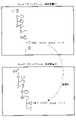
- FIG. FIG. 4 is a diagram showing a display example of an engineering tool according to an embodiment of the present disclosure
- FIG. FIG. 4 is a diagram showing a display example of an operation tool according to an embodiment of the present disclosure
- FIG. 3 is a diagram illustrating an example of packet conversion according to an embodiment of the present disclosure
- 4 is a flow chart showing an example of a procedure of processing of a control device according to an embodiment of the present disclosure
- It is a figure which shows schematic structure of the control system which concerns on a reference example.
- FIG. 4 is a functional block diagram showing functions provided in a control device according to a reference example;
- FIG. 1 is a diagram showing a schematic configuration of a control system according to one embodiment of the present disclosure. As shown in FIG. 1, in this embodiment, it is assumed that the control device C1 and the control device C2 are connected by a digital communication network (hereinafter referred to as "communication network”) NW.
- NW digital communication network
- the control device C1 is a control device for controlling (controlling and measuring) the equipment to be controlled.
- the control device C2 is a device provided independently of the control device C1, and controls (controls and measures) the control target equipment.
- the control device C1 and the control device C2 control different devices to be controlled.
- the control device C1 is provided with an IOA (I/O adapter), an IOM (I/O module), and a CPU (control unit).
- the control device C1 is provided with IOA_1, IOA_2, and IOA_3 as IOAs, and CPU_1 as a CPU.
- the control device C2 is similarly provided with an IOA and a CPU. That is, it is assumed that the control device C2 is provided with an IOA_4 as an IOA and a CPU_2 as a CPU.
- each device is connected to each other by a communication network NW, and can transmit and receive information.
- the information transmission direction is not limited.
- the communication network NW is an I/O communication network and performs high-speed communication in the digital domain.
- the communication network NW is Ethernet.
- packet communication is performed in the communication network NW, but other communication methods may be applied.
- IOAs are individually distinguished and described, they are indicated individually as IOA_1 and the like, and when they are not individually distinguished (in the case of explanation as an I/O adapter), they are indicated as IOA.
- the CPU and IOM are similarly shown and described.
- the IOA is arranged for the control device C1 and the control device C2, and is a device for inputting information from outside the device into the device.
- the IOA for example, packetizes the input information and transmits the information to the communication network NW.
- the IOA may have the function of information output.
- IOA_1 (IOM_1) is connected to equipment (instrument PT) such as oscillator OSC and switch (S/W) S, and receives various input signals.
- equipment such as oscillator OSC and switch (S/W) S
- the signal from oscillator OSC is an analog signal
- the signal from switch S is a digital signal.
- a digital signal is analog-to-digital converted by an IOM (an I/O module, IOM_1 in FIG. 1) mounted under IOA_1 and input to IOA_1.
- the input signal is, for example, an input signal from an instrument, a sensor, or the like, but is not limited to the above as long as it is used for control.
- IOA and IOM form the input section of the control device.
- IOA_1 and IOM_1 are shown as the input part IN1 in the control device C1.
- the input unit IN1 receives an input signal including input information and serves as a unit that transmits the input information to the communication network NW.
- the CPU executes control of the controlled device based on the input information sent by the IOA.
- a control law is set in advance according to the device to be controlled.
- the CPU transfers input information to different control devices. That is, an input signal from oscillator OSC or the like is input to IOA_1 of controller C1 and sent to CPU_1 within controller C1.
- the CPU_1 receives input information from the input unit IN1 via the communication network NW.
- CPU_1 of the control apparatus C1 transmits input information to CPU_2 of the control apparatus C2 via the communication network NW while controlling a control object apparatus. That is, the CPU_1 transmits the received input information to the CPU_2 of the control device C2, which is another device provided independently of the control device C1, via the communication network NW.
- the CPU_1 of the control device C1 and the CPU_2 of the control device C2 may be capable of various settings via the computer PC1.
- an engineering tool for configuring the control system is provided in the computer PC1, and settings can be made for the control device C1 and the control device C2 via this engineering tool.
- the CPU_1 of the control device C1 and the CPU_2 of the control device C2 may be capable of being operated and monitored via the computer PC1.
- an operator station (operation tool) is provided in the computer PC1, and the control device C1 and the control device C2 can be operated and monitored via this tool.
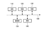
- FIG. 2 is a diagram showing an example of the hardware configuration of the control device C1 according to this embodiment.
- the control device is a computer system (computer system), for example, a CPU 110, a ROM (Read Only Memory) 120 for storing programs executed by the CPU 110, It has a RAM (Random Access Memory) 130 functioning as a work area, a hard disk drive (HDD) 140 as a large-capacity storage device, and a communication section 150 for connecting to a network or the like.
- a solid state drive (SSD) may be used as the mass storage device.
- Programs and the like executed by the CPU 110 are stored in a large-capacity storage device, and may be executed while being developed on the RAM. These units are connected via a bus 180 .
- the control device may include an input unit such as a keyboard and a mouse, and a display unit such as a liquid crystal display device for displaying data.
- an input unit such as a keyboard and a mouse
- a display unit such as a liquid crystal display device for displaying data.
- the storage medium for storing programs and the like executed by the CPU 11 is not limited to the ROM 120.
- other auxiliary storage devices such as magnetic disks, magneto-optical disks, and semiconductor memories may be used.
- a series of processes for realizing various functions to be described later is recorded in the hard disk drive 140 or the like in the form of a program. As a result, various functions to be described later are realized.
- the program may be pre-installed in the ROM 120 or other storage medium, provided in a state stored in a computer-readable storage medium, or delivered via wired or wireless communication means. may be applied.
- Computer-readable storage media include magnetic disks, magneto-optical disks, CD-ROMs, DVD-ROMs, semiconductor memories, and the like.
- the control device C2 also has the same hardware configuration as the control device C1.
- FIG. 3 is a functional block diagram showing the functions of the control device C1.
- oscillator OSC is shown as instrument PT.
- IOM_1 and IOA_1, IOM_2 and IOA_2, IOM_3 and IOA_3, and CPU_1 are provided and connected by a communication network NW.
- IOM_4, IOA_4, and CPU2 are provided, and are connected by a communication network NW. Further, each part of the control device C1 and each part of the control device C2 are connected by a communication network NW.
- a signal from instrument PT enters IOM_1 of controller C1, and input information is transmitted to CPU_1 via IOA_1. That is, the input unit IN1 performs one-to-one communication with the CPU_1. In other words, the input IN1 becomes a dedicated input for the CPU_1. Therefore, highly reliable information transmission from the input unit IN1 to the CPU_1 is possible. On the other hand, when the input unit IN1 transmits information to the CPU_1, it cannot transmit information to the other CPU_2.
- the CPU_1 processes the packet received from the input unit IN1 and transfers the information to the CPU_2 of the control device C2. For example, CPU_1 processes the destination information of the received packet, etc., and transfers the packet including the input information from the meter PT to CPU_2 via the communication network NW.
- the CPU_1 transfers data in the data format from the input unit IN1. That is, the CPU_1 transfers data from the input unit IN1 while retaining information, and the CPU_2 performs processing assuming that the information has been transferred directly from the input unit IN1. Therefore, as shown in FIG. 3, when viewed from CPU_2, it appears that data is sent from a virtual input unit IN1 (IOM_1 surrounded by a dotted line in FIG. 3). That is, the input unit IN1 is shared between the CPU_1 and the CPU_2, and the input unit IN1 is virtualized when viewed from the CPU_2. The details of the packet conversion method will be described later.
- FIG. 4 shows a display example of the engineering tool of the computer PC1.
- FIG. 4 shows a display example for the control device C1 and a display example for the control device C2.
- the engineering tool allows configuration of the input section.
- the name of the input unit IN1 (for example, IOM_1) is displayed.
- the engineering tool shows not only the name of the input, but also its properties.
- the property is, for example, specification information of the input unit (for example, input current range information, etc.).
- the properties of modules and signals assigned to them are displayed as ⁇ , ⁇ , and XXX.
- the object of the input section IN1 is also displayed for the control device C2.
- the object may be displayed as representing the input unit IN1 itself, or may be displayed as a virtualized input unit.
- the object of the input section IN1 is displayed for both the control device C1 and the control device C2.
- FIG. 5 shows a display example of the operation tool of the computer.
- FIG. 5 shows a display example for the control device C1 and a display example for the control device C2.
- the display is made as if an input is being made from the input unit IN1.
- the input information (input value) in FIG. 5 for example, numerical values, which are specific data measured by the meter PT, are displayed.
- FIG. 6 is a diagram showing an example of packet conversion according to the present embodiment.
- FIG. 6 shows data A sent from IOM_1 to IOA_1, packet B sent from IOA_1 to CPU_1, and packet C sent from CPU_1 to CPU_2.
- the input unit IN1 communicates a packet as a packet including destination information (destination identification information) whose destination is the CPU_1, sender information (sender identification information) whose sender is the input unit, and input information. Send to network NW.
- the CPU_1 receives the packet, converts the destination information into information addressed to another control unit (CPU_2), and transmits the information to the other control unit (CPU_2).
- data A is formed by IOM_1 and sent to IOA.
- data A includes destination identification information, sender identification information, and input information.
- Destination identification information is unique information indicating a device to which data A is to be sent. Since IOA_1 sends to CPU_1, the destination identification information is set corresponding to CPU_1.
- the sender identification information is unique information indicating the device that sent the data A.
- FIG. That is, the caller identification information is information indicating that the input is from the input unit. Since data A is transmitted from IOM_1, the sender identification information is set corresponding to IOM_1. The caller identification information should be able to identify the input unit.
- Input information is input data. That is, the input information is information input from sensors such as the oscillator OSC and the switch S.
- one input unit transmits information to one CPU, so there is one destination identification information and one sender identification information.
- IOA_1 data A is converted into the structure of packet B. Specifically, destination address information is set based on the destination identification information, and sender address information is set based on the sender identification information.
- the destination address information and the source address information serve as communication headers. Destination address information corresponding to the destination identification information and sender address information corresponding to the sender identification information are preset in the IOA_1.
- the communication header may also contain other information. For example, the communication header may include type information and the like in the case of Ethernet communication.
- the input information is sent to the CPU_1 on the communication network NW.
- the CPU_1 receives the packet B and controls the device to be controlled based on the input information. Specifically, the input information is developed on the memory of the CPU_1, and the control calculation is executed.
- the CPU_1 converts the packet B into the structure of the packet C.
- the destination identification information is set corresponding to CPU_2 (replacement).
- Virtual IOM_1 is a virtual IO module corresponding to IOM_1. Since direct transmission from IOM_1 to CPU_2 is not actually performed, virtual IOM_1 is set as the source identification information for virtual IOM_1. By setting it as virtual IOM_1, CPU_2 can recognize that it is a virtual module of IOM_1, but in the conversion to packet C, the sender identification information is not corrected and the sender identification information corresponding to IOM_1 is maintained. good too.
- the CPU_1 sets destination address information corresponding to the destination identification information after replacement, and sets caller address information corresponding to the caller identification information after replacement.
- the destination address information and the source address information serve as communication headers.
- CPU_1 sets CPU_2, which is another device, as a destination.
- the input information is sent from the CPU_1 to the CPU_2 on the communication network NW.
- the CPU_1 converts the destination address information and transfers it to the CPU_2, the input information input to the input section corresponding to the CPU_1 can also be received by the CPU_2 at the same sampling period. Since CPU_2 seems to have received the input information from virtual IOM_1, the IOM is virtualized. Then, the CPU_2 controls the device to be controlled based on the received input information.
- FIG. 6 is an example and is not limited.
- the communication header may include protocol headers such as type code and IP layer.
- the destination identification information and the source identification information may be converted or deleted as long as the input information is correctly transmitted from the input unit to CPU_1 and from CPU_1 to CPU_2.
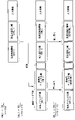
- FIG. 7 is a flow chart showing an example of the procedure of the processing of the control device C1 according to this embodiment.
- the flow shown in FIG. 7 is repeatedly executed at a predetermined control cycle, for example, when the control device C1 is in operation.
- an input signal is input to the input unit IN1 (S101). That is, input information is input to IOM_1 as an input signal.
- the CPU_1 executes control of the device to be controlled based on the sent data (especially the input information) (S106).
- CPU_1 converts the sent data to transmit the communication header (destination address information and source address information) to CPU_2 (S107).
- the CPU_2 Upon receiving the data, the CPU_2 executes control of the control target device based on the input information. By processing data in this manner, not only CPU_1 but also CPU_2 can receive input information and execute control.
- the communication load may increase due to an increase in the amount of information and an increase in the communication cycle.
- the input unit transmits input information to one CPU_1 and then transmits information from CPU_1 to CPU_2 as in the present embodiment, the processing load is reduced and the reliability of communication is improved. Effective.
- FIG. 8 and 9 show the configuration of a control device according to a reference example.
- a reference example is a configuration in which an input signal is branched and input to a plurality of control devices.
- each of the control device C3 and the control device C4 performs control using an input signal from the instrument PT such as the oscillator OSC and the switch S.
- FIG. 8 is a configuration of a reference example corresponding to the configuration of FIG. 3 in this embodiment.
- each control device C3 and control device C4 controls each device to be controlled.
- An input signal from the oscillator OSC and an input signal from the switch S are branched to the controllers C3 and C4, respectively, and input to the respective IOAs. Therefore, it is necessary to arrange an IOA for inputting an input signal to each of the control devices C3 and C4.
- FIG. 9 is a diagram showing a specific example of the configuration of the control device C3 and the control device C4 shown in FIG.
- oscillator OSC is shown as instrument PT.
- IOM_1 and IOA_1, IOM_2 and IOA_2, IOM_3 and IOA_3, and CPU_3 are provided, and are connected by a communication network NW.
- IOM5 and IOA_5, IOM_4 and IOA_5, and CPU_4 are provided, which are respectively connected by the communication network NW.
- a signal from the instrument PT is branched by a distributor (power supply device) DS.
- the input signal branched by distributor DS enters IOM_5 via isolator (signal isolator) ISO and is sent to CPU_4 via IOA_5.
- the CPU_1 controls the device to be controlled based on the input signal input at the input unit IN1, and controls other devices.
- the input information is sent to the CPU_2 which is the control unit of the . Therefore, the CPU_2 can also perform control based on the input information.
- the input unit IN1 can be shared, and the configuration of the input unit IN1 can be omitted. That is, the input unit IN1 can be virtualized. Cost reduction can be expected by suppressing the required number of input units IN1.
- the CPU_1 transmits the input information to the CPU_2 together with the information (source information) indicating that the input is from the input unit IN1, so that the CPU_2 can recognize that the input is from the input unit. That is, the input unit IN1 can be virtualized.
- CPU_1 By setting CPU_2 as a destination and sending input information to CPU_2, CPU_1 can more reliably send input information from CPU_1 to CPU_2.
- control device in this embodiment is provided in a power plant.
- Equipment to be controlled is, for example, a turbine, a boiler, ancillary equipment, and the like.
- the control device is not limited to power plants and can be widely applied.
- a control device (C1) is a control device that controls a device to be controlled, and is an input unit (IN1) that receives an input signal including input information and sends the input information to a digital communication network (NW). and a control unit (CPU_1) that receives the input information from the input unit via the digital communication network and performs control based on the input information, wherein the control unit receives the input information , via the digital communication network, to the control unit (CPU_2) that controls the control target equipment in another device (C2) that is provided independently of the control device.
- I1 input unit
- NW digital communication network
- CPU_1 control unit that receives the input information from the input unit via the digital communication network and performs control based on the input information, wherein the control unit receives the input information , via the digital communication network, to the control unit (CPU_2) that controls the control target equipment in another device (C2) that is provided independently of the control device.
- the control unit controls the controlled device based on the input information input by the input unit, and also transmits the input information to other control units. Therefore, other control units can also perform control based on the input information.
- the input section can be shared, so that the configuration of the input section can be omitted, as compared with the case where the input section is provided for each control section, for example. That is, the input section can be virtualized. Cost reduction can be expected by suppressing the required number of input units.
- control unit may transmit the input information to the other control unit together with information indicating that the input is from the input unit.
- the control unit transmits input information including information indicating that the input is from the input unit to the other control unit.
- input information including information indicating that the input is from the input unit to the other control unit.
- the input section can be virtualized.
- control unit may set the other control unit as a destination and transmit the input information to the other control unit.
- the control unit sets the other control unit as the destination and transmits the input information to the other control unit, so that the control unit can more reliably transmit the input information to the other control unit. can be sent to That is, the input section can be virtualized.
- the input unit transmits the packet as a packet including destination information whose destination is the control unit, sender information whose source is the input unit, and the input information.
- the control unit may receive the packet, convert the destination information into information destined for the other control unit, and transmit the packet to the other control unit.
- the input unit sends a packet to the digital communication network as a packet including destination information whose destination is the control unit, source information whose source is the input unit, and input information.
- the controller receives the packet. Therefore, one-to-one communication becomes possible between the input unit and the control unit, and the reliability of information transmission can be improved.
- the control unit converts the destination information into information destined for another control unit, and transmits the information to the other control unit. Therefore, other control units can also be controlled based on the input information. That is, the input section can be virtually shared by the control section and another control section.
- a control method is a control method for a control device that controls a device to be controlled, wherein an input signal including input information is input in an input unit, the input information is sent to a digital communication network; receiving the input information from the input unit via the digital communication network and performing control based on the input information; and transmitting the received input information via the digital communication network to the control and transmitting to a control unit that controls a device to be controlled in another device that is provided independently of the device.
- a control program is a control program for a control device that controls a device to be controlled, wherein an input signal including input information is input in an input unit, processing for sending the input information to a digital communication network, and control a process in which a unit receives the input information from the input unit via the digital communication network and performs control based on the input information; and a process of transmitting to a control unit that controls the control target device in another device provided independently of the device.
- Communication unit 180 Bus A: Data B: Packet C: Packets C1-C4: Control device CPU_1-CPU_4: CPU (control unit) DS: Distributor IN1: Input section IOA_1-IOA_5: IOA (I/O adapter) IOM_1-IOM_5: IOMs (I/O modules) ISO: isolator NW: communication network OSC: oscillator PT: instrument S: switch
Landscapes
- Engineering & Computer Science (AREA)
- Computer Networks & Wireless Communication (AREA)
- Signal Processing (AREA)
- Physics & Mathematics (AREA)
- General Physics & Mathematics (AREA)
- Automation & Control Theory (AREA)
- Programmable Controllers (AREA)
- Small-Scale Networks (AREA)
- Selective Calling Equipment (AREA)
Abstract
Description
図2に示すように、制御装置は、コンピュータシステム(計算機システム)であり、例えば、CPU110と、CPU110が実行するプログラム等を記憶するためのROM(Read Only Memory)120と、各プログラム実行時のワーク領域として機能するRAM(Random Access Memory)130と、大容量記憶装置としてのハードディスクドライブ(HDD)140と、ネットワーク等に接続するための通信部150とを備えている。大容量記憶装置としては、ソリッドステートドライブ(SSD)を用いることとしてもよい。CPU110が実行するプログラム等は、大容量記憶装置に記憶されており、RAM上に展開しながら実行することとしてもよい。これら各部は、バス180を介して接続されている。
図6は、本実施形態に係るパケットの変換の一例を示す図である。図6では、IOM_1からIOA_1へ送付されるデータA、IOA_1からCPU_1へ送付されるパケットB、そして、CPU_1からCPU_2へ送付されるパケットCのそれぞれを示している。概要としては、入力部IN1は、CPU_1を宛先とする宛先情報(宛先識別情報)、入力部を発信元とする発信元情報(発信元識別情報)、及び入力情報を含むパケットとして、パケットを通信ネットワークNWへ送る。そして、CPU_1は、パケットを受信し、宛先情報を他の制御部(CPU_2)を宛先とする情報へ変換して、他の制御部(CPU_2)へ送信する。
本開示に係る制御装置(C1)は、制御対象機器を制御する制御装置であって、入力情報を含む入力信号が入力され、前記入力情報をデジタル通信ネットワーク(NW)へ送る入力部(IN1)と、前記デジタル通信ネットワークを介して前記入力部から前記入力情報を受信し、前記入力情報に基づいて制御を行う制御部(CPU_1)と、を備え、前記制御部は、受信した前記入力情報を、前記デジタル通信ネットワークを介して、前記制御装置とは独立して設けられた他の装置(C2)において制御対象機器器を制御する制御部(CPU_2)へ送信する。
120 :ROM
130 :RAM
140 :ハードディスクドライブ
150 :通信部
180 :バス
A :データ
B :パケット
C :パケット
C1-C4 :制御装置
CPU_1-CPU_4:CPU(制御部)
DS :ディストリビュータ
IN1 :入力部
IOA_1-IOA_5:IOA(I/Oアダプター)
IOM_1-IOM_5:IOM(I/Oモジュール)
ISO :アイソレータ
NW :通信ネットワーク
OSC :発振器
PT :計器
S :スイッチ
Claims (6)
- 制御対象機器を制御する制御装置であって、
入力情報を含む入力信号が入力され、前記入力情報をデジタル通信ネットワークへ送る入力部と、
前記デジタル通信ネットワークを介して前記入力部から前記入力情報を受信し、前記入力情報に基づいて制御を行う制御部と、
を備え、
前記制御部は、受信した前記入力情報を、前記デジタル通信ネットワークを介して、前記制御装置とは独立して設けられた他の装置において制御対象機器を制御する制御部へ送信する制御装置。 - 前記制御部は、前記入力部からの入力であることを表す情報と共に前記入力情報を前記他の制御部へ送信する請求項1に記載の制御装置。
- 前記制御部は、前記他の制御部を宛先として設定し、前記入力情報を前記他の制御部へ送信する請求項1または2に記載の制御装置。
- 前記入力部は、前記制御部を宛先とする宛先情報、前記入力部を発信元とする発信元情報、及び前記入力情報を含むパケットとして、前記パケットを前記デジタル通信ネットワークへ送り、
前記制御部は、前記パケットを受信し、前記宛先情報を前記他の制御部を宛先とする情報へ変換して、前記他の制御部へ送信する請求項1から3のいずれか1項に記載の制御装置。 - 制御対象機器を制御する制御装置の制御方法であって、
入力部において、入力情報を含む入力信号が入力され、前記入力情報をデジタル通信ネットワークへ送る工程と、
制御部が、前記デジタル通信ネットワークを介して前記入力部から前記入力情報を受信し、前記入力情報に基づいて制御を行う工程と、
受信した前記入力情報を、前記デジタル通信ネットワークを介して、前記制御装置とは独立して設けられた他の装置において制御対象機器を制御する制御部へ送信する工程と、
を有する制御方法。 - 制御対象機器を制御する制御装置の制御プログラムであって、
入力部において、入力情報を含む入力信号が入力され、前記入力情報をデジタル通信ネットワークへ送る処理と、
制御部が、前記デジタル通信ネットワークを介して前記入力部から前記入力情報を受信し、前記入力情報に基づいて制御を行う処理と、
受信した前記入力情報を、前記デジタル通信ネットワークを介して、前記制御装置とは独立して設けられた他の装置において制御対象機器を制御する制御部へ送信する処理と、
をコンピュータが実行させるための制御プログラム。
Priority Applications (3)
| Application Number | Priority Date | Filing Date | Title |
|---|---|---|---|
| US18/284,695 US12323259B2 (en) | 2021-03-31 | 2022-02-09 | Control device, control method thereof, and control program |
| DE112022001939.5T DE112022001939T5 (de) | 2021-03-31 | 2022-02-09 | Steuervorrichtung, steuerverfahren davon und steuerprogramm |
| CN202280025399.1A CN117157947A (zh) | 2021-03-31 | 2022-02-09 | 控制装置及其控制方法以及控制程序 |
Applications Claiming Priority (2)
| Application Number | Priority Date | Filing Date | Title |
|---|---|---|---|
| JP2021060071A JP7665380B2 (ja) | 2021-03-31 | 2021-03-31 | 制御装置、及びその制御方法並びに制御プログラム |
| JP2021-060071 | 2021-03-31 |
Publications (1)
| Publication Number | Publication Date |
|---|---|
| WO2022209334A1 true WO2022209334A1 (ja) | 2022-10-06 |
Family
ID=83455906
Family Applications (1)
| Application Number | Title | Priority Date | Filing Date |
|---|---|---|---|
| PCT/JP2022/005157 Ceased WO2022209334A1 (ja) | 2021-03-31 | 2022-02-09 | 制御装置、及びその制御方法並びに制御プログラム |
Country Status (5)
| Country | Link |
|---|---|
| US (1) | US12323259B2 (ja) |
| JP (1) | JP7665380B2 (ja) |
| CN (1) | CN117157947A (ja) |
| DE (1) | DE112022001939T5 (ja) |
| WO (1) | WO2022209334A1 (ja) |
Citations (1)
| Publication number | Priority date | Publication date | Assignee | Title |
|---|---|---|---|---|
| JP2009278328A (ja) * | 2008-05-14 | 2009-11-26 | Mitsubishi Electric Corp | 設備管理システム及び端末コントローラ |
Family Cites Families (9)
| Publication number | Priority date | Publication date | Assignee | Title |
|---|---|---|---|---|
| JPS5818740A (ja) | 1981-07-28 | 1983-02-03 | Toshiba Corp | デ−タ伝送装置 |
| US5384806A (en) | 1991-09-23 | 1995-01-24 | At&T Bell Laboratories | Modem with time-invariant echo path |
| US7424328B2 (en) * | 2006-01-03 | 2008-09-09 | De Silvio Louis F | Apparatus and method for wireless process control |
| US8611356B2 (en) * | 2009-11-13 | 2013-12-17 | Exalt Communications Incorporated | Apparatus for ethernet traffic aggregation of radio links |
| JP5609819B2 (ja) * | 2011-08-22 | 2014-10-22 | ブラザー工業株式会社 | 通信制御装置、通信制御方法、及び通信制御プログラム |
| JP5894516B2 (ja) * | 2012-10-05 | 2016-03-30 | 株式会社日立製作所 | 制御システム |
| JP6311636B2 (ja) * | 2015-03-31 | 2018-04-18 | 横河電機株式会社 | 無線中継装置、無線通信システム、及び無線中継方法 |
| CN110050237B (zh) * | 2017-11-06 | 2021-03-12 | 三菱电机株式会社 | 数据收集装置、数据收集方法及记录介质 |
| US11204594B2 (en) * | 2018-12-13 | 2021-12-21 | Fisher-Rosemount Systems, Inc. | Systems, methods, and apparatus to augment process control with virtual assistant |
-
2021
- 2021-03-31 JP JP2021060071A patent/JP7665380B2/ja active Active
-
2022
- 2022-02-09 DE DE112022001939.5T patent/DE112022001939T5/de active Pending
- 2022-02-09 US US18/284,695 patent/US12323259B2/en active Active
- 2022-02-09 WO PCT/JP2022/005157 patent/WO2022209334A1/ja not_active Ceased
- 2022-02-09 CN CN202280025399.1A patent/CN117157947A/zh active Pending
Patent Citations (1)
| Publication number | Priority date | Publication date | Assignee | Title |
|---|---|---|---|---|
| JP2009278328A (ja) * | 2008-05-14 | 2009-11-26 | Mitsubishi Electric Corp | 設備管理システム及び端末コントローラ |
Also Published As
| Publication number | Publication date |
|---|---|
| DE112022001939T5 (de) | 2024-01-25 |
| JP7665380B2 (ja) | 2025-04-21 |
| US12323259B2 (en) | 2025-06-03 |
| JP2022156404A (ja) | 2022-10-14 |
| US20240171417A1 (en) | 2024-05-23 |
| CN117157947A (zh) | 2023-12-01 |
Similar Documents
| Publication | Publication Date | Title |
|---|---|---|
| US8671310B2 (en) | Method and system for redundantly controlling a slave device | |
| US20190036730A1 (en) | Connection unit, monitoring system and method for operating an automation system | |
| US20070288204A1 (en) | Device for remote diagnostics of a field device | |
| JP2013030187A (ja) | プロセス制御システムにおいてフィールド装置をコントローラに通信可能な状態で連結する機器および方法 | |
| CN110325930B (zh) | 安全系统和安全控制器 | |
| JP2016062611A (ja) | プロセス制御システム内で、オンオフバルブをコントローラに通信可能に接続する方法、装置、及び記憶媒体 | |
| JP2016129025A (ja) | フィールドデバイスをプロセス制御システムのコントローラに通信的に連結する装置及び方法 | |
| EP3547049B1 (en) | Safety control system and safety control unit | |
| US10007633B2 (en) | Field bus coupler for connecting input/output modules to a field bus, and method of operation for a field bus coupler | |
| CN102970335B (zh) | 通信系统 | |
| CN102809957A (zh) | 用于标识基金会现场总线链接装置的系统和方法 | |
| JP5792866B2 (ja) | プロフィバスdpのマスタ装置 | |
| JP2022156404A (ja) | 制御装置、及びその制御方法並びに制御プログラム | |
| JP4992573B2 (ja) | レイヤ2スイッチ、通信機器及びそれらに用いるデータ部エラー検出方法並びにそのプログラム | |
| US20220292046A1 (en) | Connection of input and / or output modules to a fieldbus with a higher-level controller | |
| US11489697B2 (en) | Transmission of data on a local bus | |
| US20160246273A1 (en) | Controller | |
| US11092945B2 (en) | Control device, control method, and non-transitory storage medium storing control program | |
| JP7277206B2 (ja) | 通信制御装置および方法 | |
| CN204944662U (zh) | 检重秤系统 | |
| KR20130108197A (ko) | AS-i 장치 | |
| JP2008109735A (ja) | 分散型電源用転送遮断システム | |
| JP2015065570A (ja) | 伝送装置、伝送装置の制御方法 | |
| KR100695523B1 (ko) | 다중-입력 동기화 스위치 콘트롤러를 이용한 입출력데이터 제어장치 | |
| JP2021144376A (ja) | 電動バルブアクチュエータ、及び当該電動バルブアクチュエータを使用したシステム |
Legal Events
| Date | Code | Title | Description |
|---|---|---|---|
| 121 | Ep: the epo has been informed by wipo that ep was designated in this application |
Ref document number: 22779563 Country of ref document: EP Kind code of ref document: A1 |
|
| WWE | Wipo information: entry into national phase |
Ref document number: 18284695 Country of ref document: US |
|
| WWE | Wipo information: entry into national phase |
Ref document number: 112022001939 Country of ref document: DE |
|
| 122 | Ep: pct application non-entry in european phase |
Ref document number: 22779563 Country of ref document: EP Kind code of ref document: A1 |
|
| WWG | Wipo information: grant in national office |
Ref document number: 18284695 Country of ref document: US |