WO2022209264A1 - 画像処理装置、画像処理プログラム、及び、画像処理方法 - Google Patents
画像処理装置、画像処理プログラム、及び、画像処理方法 Download PDFInfo
- Publication number
- WO2022209264A1 WO2022209264A1 PCT/JP2022/004076 JP2022004076W WO2022209264A1 WO 2022209264 A1 WO2022209264 A1 WO 2022209264A1 JP 2022004076 W JP2022004076 W JP 2022004076W WO 2022209264 A1 WO2022209264 A1 WO 2022209264A1
- Authority
- WO
- WIPO (PCT)
- Prior art keywords
- image processing
- image
- processing
- image data
- extended
- Prior art date
- Legal status (The legal status is an assumption and is not a legal conclusion. Google has not performed a legal analysis and makes no representation as to the accuracy of the status listed.)
- Ceased
Links
Images




Classifications
-
- G—PHYSICS
- G06—COMPUTING OR CALCULATING; COUNTING
- G06T—IMAGE DATA PROCESSING OR GENERATION, IN GENERAL
- G06T1/00—General purpose image data processing
- G06T1/20—Processor architectures; Processor configuration, e.g. pipelining
-
- G—PHYSICS
- G06—COMPUTING OR CALCULATING; COUNTING
- G06T—IMAGE DATA PROCESSING OR GENERATION, IN GENERAL
- G06T3/00—Geometric image transformations in the plane of the image
- G06T3/40—Scaling of whole images or parts thereof, e.g. expanding or contracting
- G06T3/4053—Scaling of whole images or parts thereof, e.g. expanding or contracting based on super-resolution, i.e. the output image resolution being higher than the sensor resolution
-
- G—PHYSICS
- G06—COMPUTING OR CALCULATING; COUNTING
- G06T—IMAGE DATA PROCESSING OR GENERATION, IN GENERAL
- G06T5/00—Image enhancement or restoration
- G06T5/70—Denoising; Smoothing
-
- H—ELECTRICITY
- H04—ELECTRIC COMMUNICATION TECHNIQUE
- H04N—PICTORIAL COMMUNICATION, e.g. TELEVISION
- H04N23/00—Cameras or camera modules comprising electronic image sensors; Control thereof
- H04N23/60—Control of cameras or camera modules
Definitions
- the present disclosure relates to an image processing device, an image processing program, and an image processing method.
- Patent Document 1 discloses a processor that sequentially applies a plurality of image processes to RAW image data output from an image sensor. Multiple image processing includes pre-processing, white balance, demosaicing, color conversion, color correction, and post-processing. The final image data is generated by a series of image processing flows that are applied sequentially. A series of image processing flows that are applied sequentially is also called an image processing pipeline.
- the processor described in Patent Document 1 is typically provided as a system-on-chip as a general-purpose processing unit.
- it is common to incorporate software that applies some kind of image processing to the image data output from the image processing pipeline in the latter stage of the image processing pipeline.
- the software installed in the latter stage performs processing based on the characteristics of the image data output from the image processing pipeline, there are cases where the performance of the software cannot be fully exhibited.
- the present disclosure provides a technique capable of imparting scalability to a series of image processing flows that are applied sequentially.
- An image processing device includes an image sensor, a pipeline processing unit, a storage unit, an extended image processing unit, and a switching unit.
- the image sensor produces at least one RAW image data.
- the pipeline processing unit performs a series of image processing groups on each of at least one piece of RAW image data generated by the image sensor so that the image data resulting from the preceding image processing is subjected to the succeeding image processing.
- the extended image processing unit executes extended image processing different from each image processing included in the image processing group.
- the storage unit stores a definition designating target image processing, which is image processing to be bypassed among image processing included in the image processing group, and extended image processing.
- the switching unit selects the intermediate image data, which is the result of the image processing before the target image processing, as the target of the extended image processing based on the definition stored in the storage unit in response to the satisfaction of the predetermined switching condition. , the flow of processing in the image processing group is switched.
- FIG. 1 is a block diagram showing the hardware configuration of an image processing apparatus according to an embodiment
- FIG. 2 is a block diagram illustrating a series of image processing groups
- FIG. FIG. 4 is a block diagram illustrating processing for bypassing part of preprocessing
- 4 is a flow chart of an image processing method including a switching step
- 4 is a flowchart of extended image processing steps in the image processing method
- It is a schematic diagram explaining super-resolution processing. It is a block diagram explaining the modification of extended image processing.
- FIG. 1 is a block diagram showing the hardware configuration of an image processing apparatus according to an embodiment.
- An image processing apparatus 1 shown in FIG. 1 is a device having an imaging function, such as a smartphone.
- the image processing apparatus 1 sequentially applies a series of image processing groups to image data.
- the flow of a series of image processing groups is also referred to as an image processing pipeline.
- the image processing apparatus 1 includes an image sensor 10, a processor 11, a memory 12 (an example of a storage section), a storage 13, an input section 14, and an output section 15.
- Processor 11 is connected to image sensor 10, memory 12, storage 13, input section 14, and output section 15 so as to be able to communicate with each other.
- the image sensor 10 is a solid-state imaging device and outputs RAW image data.
- RAW image data is color image data recorded in a mosaic arrangement.
- An example of a mosaic array is the Bayer array.
- the image sensor 10 may have a continuous shooting function. In this case, the image sensor 10 generates a series of RAW image data.
- the processor 11 is an arithmetic device that executes an image processing pipeline, and is, for example, an ISP (Image Signal Processor) optimized for image signal processing.
- the processor 11 may be not only an ISP but also a GPU (Graphics Processing Unit) or CPU (Central Processing Unit). Depending on the type of image processing in the image processing pipeline, the ISP may be combined with the GPU or CPU to execute each image processing.
- the processor 11 executes an image processing pipeline for each RAW image data output from the image sensor 10 .
- the memory 12 and storage 13 are storage media.
- the memory 12 stores program modules to be executed by the processor 11, definition data, RAW image data, intermediate image data to be described later, and the like.
- the memory 12 is, for example, SDRAM (Synchronous Dynamic Random Access Memory).
- the storage 13 stores image data processed by the image processing pipeline. Image data processed by the image processing pipeline is, for example, RGB image data or YUV image data.
- the storage 13 is, for example, an HDD (Hard Disk Drive). Note that the memory 12 and the storage 13 are not particularly limited as long as they are storage media.
- the memory 12 and storage 13 may be configured with a single piece of hardware.
- the memory 12 includes a pipeline processing module 121 (an example of a pipeline processing unit) for executing an image processing pipeline.
- the processor 11 refers to the memory 12 and executes the image processing pipeline.
- the memory 12 also stores definition data 122, a switching module 123 (an example of a switching unit), and an extended image processing module 124 (an example of an extended image processing unit) for realizing switching of image processing pipelines, which will be described later. Store.
- the input unit 14 is a user interface that accepts user operations, and is an operation button as an example.
- the output unit 15 is a device that displays image data, and is, for example, a display device.
- the input unit 14 and the output unit 15 may be composed of single hardware such as a touch screen.
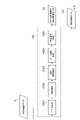
- FIG. 2 is a block diagram illustrating a series of image processing groups.
- Processor 11 executes image processing pipeline P2 based on pipeline processing module 121 .
- the processor 11 loads RAW image data stored in the memory 12 (load processing P1).
- the processor 11 sequentially executes a plurality of image processes on the RAW image data (image processing pipeline P2).
- the processor 11 obtains YUV image data as a processing result.
- the processor 11 outputs the processing result to the output unit 15 or stores it in the storage 13 (display/storage processing P3).
- Pipeline processing module 121 is a program that causes processor 11 to perform the operations described above.
- the pipeline processing module 121 causes the processor 11 to sequentially execute preprocessing P20, white balance processing P21, demosaicing processing P22, color correction processing P23, and postprocessing P24 as the image processing pipeline P2.
- the pre-processing P20 image processing is performed on Bayer format image data, which is RAW image data. Details of the preprocessing P20 will be described later.
- the white balance processing P21 the intensity of each RGB color component is corrected for the image data on which the preprocessing P20 has been executed.
- the demosaicing process P22 pixels lacking color information in the Bayer format are interpolated for the image data on which the white balance process P21 has been performed, and RGB image data is generated.
- color correction processing P23 the RGB image data is color-corrected.
- post-processing P24 color space conversion from the RGB format to the YUV format and image processing for the YUV format are performed.
- the image processing pipeline P2 shown in FIG. 2 is an example and can take various forms.
- the image processing pipeline P2 is not limited to the example shown in FIG. 2, and the order of image processing shown in FIG. 2 can be changed, image processing can be deleted, and new image processing can be added.
- the image processing apparatus 1 has a function of selecting a process bypass for each image processing in the image processing pipeline P2 as necessary. After bypassing the target image processing, the image processing apparatus 1 executes the extended image processing P4 instead of the target image processing.
- the target image processing is bypassed image processing among the image processing included in the image processing pipeline P2.
- the extended image processing P4 is processing different from each image processing in the image processing pipeline P2. This provides a new image processing option to the image processing pipeline P2.
- a process P5 including an image processing pipeline P2 and extended image processing P4 is executed by the processor 11.
- the user creates the definition data 122 so that one or more image processes included in the image processing pipeline P2 are bypassed according to the content of the extended image processing P4.
- Definition data 122 is stored in memory 12 .
- the definition data 122 includes a definition indicating which image processing is the target image processing, and a definition indicating that the image processing to be executed after the bypass is extended image processing.
- the extended image processing P4 is noise reduction processing based on a plurality of image data
- Noise reduction processing based on a plurality of image data is called MFNR (Multi-Frame Noise Reduction), and reduces noise contained in image data by calculating the average value of pixels in continuously shot image data.
- moving objects are detected based on the difference in pixel values between images in order to prevent multiple blurring due to synthesis.
- it In order to properly detect a moving object, it must be determined whether the difference in pixel values between images is caused by the movement of the object or by noise contained in the images.
- it is important to appropriately estimate the intensity of noise contained in the image.
- the noise intensity can be accurately estimated from the ISO sensitivity at the time of shooting using factory calibration data or the like. This is because their intensities vary according to natural laws.
- the image processing pipeline P2 may include processing for changing the noise intensity of the image.
- processing includes, for example, SFNR (Single-Frame Noise Reduction) or peripheral light falloff correction processing.
- SFNR Single-Frame Noise Reduction
- Peripheral light falloff correction processing amplifies the luminance of the image peripheral region in order to improve the phenomenon that the light quantity at the periphery of the image is reduced due to the characteristics of the lens.
- the noise intensity estimation method using the law of nature described above does not assume image data that has been subjected to processing to change the noise intensity, so when such image data is targeted, sufficient estimation accuracy is achieved. may not be possible.
- the definition data 122 is generated so as to bypass the processing for changing the noise intensity of the image.
- the image data having the premise noise characteristics is input to the extended image processing P4, and more appropriate image processing is realized.
- the processor 11 bypasses the target image processing of the image processing pipeline P2 based on the switching module 123. For example, processor 11 determines whether a predetermined switching condition is satisfied.
- the predetermined switching condition is a condition for determining whether or not bypassing is necessary, and is determined in advance.
- the predetermined switching condition may be, for example, reception of a user operation to enable the extended image processing P4, or satisfaction of a predetermined condition of time or environment.
- the processor 11 bypasses the target image processing of the image processing pipeline P2 according to the definition data 122 when a predetermined switching condition is satisfied.
- the switching module 123 is a program that causes the processor 11 to perform a series of operations that bypass the target image processing described above. In the example shown in FIG.
- the preprocessing P20 is switched to the extended image processing P4 in the middle, and the extended image processing P4 is executed.
- the processing result of the extended image processing P4 is returned to the image processing pipeline P2, and white balance processing P21, demosaicing processing P22, color correction processing P23, and post-processing P24 are sequentially executed.
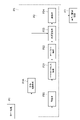
- FIG. 3 is a block diagram illustrating the process of bypassing part of the preprocessing.
- the preprocessing P20 constitutes a series of image processing groups, including base processing P201, ABF application processing P203, dark correction processing P204, and light amount adjustment processing P205.
- base processing P201 image processing such as basic correction and linearization is performed on the Bayer format image data, which is the input RAW image data D1.
- ABF application process P203 an ABF (Adaptive Bilateral Filter) is applied to the image data resulting from the base process P201 to adjust the edge strength.
- the dark correction process P204 noise is removed by subtracting the previously obtained black level from the image data that is the result of the ABF application process P203.
- the image data resulting from the dark correction process P204 is corrected so that the brightness of the image peripheral area is amplified.
- a single processed RAW image data D2 is generated as a processing result of the preprocessing P20.
- One processed RAW image data D2 is generated for one RAW image data D1.
- the processor 11 switches the image processing pipeline P2 based on the definition data 122 when a predetermined switching condition is satisfied.
- the intermediate image data D3 is generated instead of the single processed RAW image data D2.
- the intermediate image data D3 is the result of image processing immediately before the target image processing, and one intermediate image data D3 is generated for one RAW image data D1.
- the intermediate image data D3 is subject to the extended image processing P4.
- the processor 11 may store the intermediate image data D3 in the memory 12 each time it generates the intermediate image data D3.
- the processor 11 executes the extended image processing P4 based on the extended image processing module 124. As described above, the extended image processing P4 is processing different from each image processing in the image processing pipeline P2. This provides a new image processing option to the image processing pipeline P2. Processor 11 refers to memory 12 and generates single image data based on the N pieces of intermediate image data.
- the definition data 122 may include the output destination of the single image data generated by the extended image processing P4.
- the definition data 122 stores the white balance processing P21 as the output destination.
- the extended image processing module 124 causes the processor 11 to output the generated single image data to the output destination defined by the definition data 122 .
- the processing result of the extended image processing P4 is handed over to the white balance processing P21, and the image processing pipeline P2 is executed.
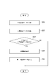
- FIG. 4 is a flow chart of an image processing method including a switching step.
- the flowchart shown in FIG. 4 is started at the timing when one piece of RAW image data D1 is read from the memory 12, for example.
- the extended image processing P4 is noise reduction processing, and that the switching condition is satisfied when a user operation enabling the noise reduction processing is received.
- the processor 11 determines whether or not the switching condition is satisfied as a determination step (step S10). If the user's operation to enable the noise reduction process has not been received (step S10: NO), the processor 11 executes the normal process (step S11) through the image processing pipeline.
- the processor 11 refers to the definition data 122 as a definition acquisition step (step S12), and performs ABF application processing P203, which is the target image processing, A definition identifying the dark correction processing P204 and the light amount adjustment processing P205, and a definition indicating that the image processing to be executed after the bypass is the noise reduction processing (extended image processing P4) are acquired.
- the processor 11 performs target image processing (ABF application processing P203, dark correction processing P204, and light amount adjustment processing P205) based on the definition obtained in the definition acquisition step (step S12). ) is set in the image processing pipeline P2 to bypass the switching process P202.
- target image processing ABSF application processing P203, dark correction processing P204, and light amount adjustment processing P205
- the processor 11 executes the image processing pipeline P2 until just before the target image processing. Specifically, the processor 11 performs the processing up to the base processing P201 immediately before the ABF application processing P203.
- the processor 11 applies noise reduction processing (extended image processing) to the intermediate image data, which is the processing result of the base processing P201, based on the definition obtained in the definition acquisition step (step S12).
- noise reduction processing extended image processing
- the flow of the image processing pipeline P2 is switched so that it becomes the processing target of P4).
- step S11 When the normal process (step S11) or the switching process (step S18) ends, the flowchart shown in FIG. 4 ends.
- the flowchart shown in FIG. 4 starts from the beginning when the processor 11 reads the next RAW image data D1 from the memory 12 .
- FIG. 5 is a flowchart of extended image processing steps in the image processing method. The flowchart shown in FIG. 5 is executed after the switching step (step S18) shown in FIG. 4 is completed.
- the processor 11 acquires the processing result of the base processing P201 as intermediate image data D3 as an intermediate image data acquisition step (step S20). Subsequently, the processor 11 causes the memory 12 to record the intermediate image data D3 obtained in the intermediate image data obtaining step (step S20) as an intermediate image data holding step (step S22).
- the processor 11 determines whether or not the number of intermediate image data D3 recorded in the memory 12 is N as a data number determination step (step S24).
- the processor 11 executes noise reduction processing as an extended image processing step (step S26).
- the processor 11 outputs the single image data, which is the processing result of the noise reduction processing, to the white balance processing P21, which is the output destination defined by the definition data 122.
- Processor 11 clears the intermediate image data in memory 12 .
- step S28 When the output step (step S28) is completed, or when it is determined that the number of intermediate image data D3 recorded in the memory 12 is not N (step S24: YES), the flow chart shown in FIG. ends. As shown in the flow chart of FIG. 5, this method executes the extended image processing step (step S26) when a predetermined number (N) of intermediate image data D3 is available, and the subsequent image processing pipeline Image data can be handed over to P2.
- the image processing pipeline for each of at least one piece of RAW image data D1 generated by the image sensor 10, the image processing pipeline is configured so that the image data resulting from the preceding image processing is subjected to the succeeding image processing. P2 is executed. Then, when a predetermined switching condition is satisfied, the intermediate image data D3, which is the result of image processing immediately before the target image processing, is processed in the image processing pipeline P2 so as to be subject to the extended image processing P4. flow can be switched.
- the image processing apparatus 1 bypasses arbitrary image processing included in the image processing pipeline P2, and performs extended image processing P4 on the intermediate image data D3. can be executed. Therefore, the image processing apparatus 1 can provide extensibility to the image processing pipeline P2.
- the image processing pipeline P2 includes processing to change the noise intensity
- the intermediate image data D3 that has not undergone the process of changing the noise intensity
- noise according to the laws of nature appears, so the noise intensity can be estimated appropriately.
- the image processing apparatus 1 performs noise reduction processing based on a plurality of pieces of intermediate image data D3, it is possible to generate single image data with improved characteristics.
- the image processing apparatus 1 can appropriately reduce noise and appropriately increase the resolution as compared with the case where noise reduction processing is performed on the processing result of the image processing pipeline P2.
- the image processing device 1 can return the result of the extended image processing P4 to the image processing pipeline P2.
- the extended image processing P4 is noise reduction processing, but the extended image processing P4 can be arbitrary processing.
- the extended image processing P4 may be image processing for a single intermediate image data D3, or may be image processing for a plurality of intermediate image data.
- Super-resolution processing is processing for increasing the resolution of image data based on a plurality of image data.
- the plurality of pieces of image data are, for example, time-series image data (eg, continuous-shot image data).
- the resolution of image data can be increased by aligning a plurality of image data and integrating pixels.
- extended image processing P4A when the extended image processing is super-resolution processing, it is referred to as extended image processing P4A.
- FIG. 6A shows how RAW image data 301, 302, and 303 are input (loaded) in chronological order.
- the time axis extends from the top to the bottom of the figure, and each piece of RAW image data is aligned with a predetermined pixel position as a reference in consideration of the ease of explanation and understanding. are displayed.
- the processor 11 acquires RAW image data 301, 302, and 303 in order.
- the input RAW image data 301, 302, and 303 each have R component pixels, G component pixels, and B component pixels in a Bayer array.
- FIG. 6B is a diagram schematically showing the RAW image data group 304 after alignment.
- the processor 11 performs sampling processing on the RAW image data group 304 after alignment. In this sampling processing, pixel values are combined for each color component at pixel intervals smaller than the pixel intervals of the input RAW image data. Combining the pixel values may be performed by simple averaging or weighted averaging of the pixel values of the RAW image data group 304 at the target pixel position.
- the processor 11 calculates the pixel value difference between the reference RAW image data and the synthesis target RAW image data at the target pixel position. If the pixel value difference is equal to or greater than the threshold, the processor 11 may estimate that the RAW image data to be synthesized has failed in registration, and may reduce the synthesis contribution of the RAW image data.
- FIG. 6C is a diagram schematically showing single RGB image data 305 composed of R, G, and B components output as a result of sampling processing.
- FIG. 7 is a block diagram illustrating a modification of extended image processing.
- the output destination of the extended image processing P4A is the color correction processing P23. That is, when the extended image processing P4A is executed, the white balance processing P21 and the demosaicing processing P22 in the image processing pipeline P2 are bypassed.
- the RGB color tone adjustment corresponding to the white balance processing P21 may be applied to the single RGB image data 305.
- FIG. The processor 11 performs color correction processing P23 and post-processing P24 on the RGB image data output by the extended image processing P4.
- the output destination of the extended image processing P4 is different than when the extended image processing P4 is MFNR, and other pipeline processing is the same.
- the image processing pipeline P2 can have extensibility such as super-resolution processing.
Landscapes
- Engineering & Computer Science (AREA)
- Physics & Mathematics (AREA)
- General Physics & Mathematics (AREA)
- Theoretical Computer Science (AREA)
- Multimedia (AREA)
- Signal Processing (AREA)
- Image Processing (AREA)
- Studio Devices (AREA)
Abstract
Description
図1は、実施形態に係る画像処理装置のハードウェア構成を示すブロック図である。図1に示される画像処理装置1は、例えばスマートフォンなどの撮像機能を有するデバイスである。画像処理装置1は、画像データに対して一連の画像処理群を順次適用する。以下では、一連の画像処理群の流れを画像処理パイプラインともいう。
図2は、一連の画像処理群を説明するブロック図である。プロセッサ11は、パイプライン処理モジュール121に基づいて画像処理パイプラインP2を実行する。最初に、プロセッサ11は、メモリ12に格納されたRAW画像データをロードする(ロード処理P1)。そして、プロセッサ11は、RAW画像データに対して複数の画像処理を順次実行する(画像処理パイプラインP2)。そして、プロセッサ11は、処理結果としてYUV画像データを得る。プロセッサ11は、処理結果を出力部15に出力させ、又は、ストレージ13に記憶させる(表示/記憶処理P3)。パイプライン処理モジュール121は、プロセッサ11が上述した動作を実行するように機能させるプログラムである。
画像処理装置1は、画像処理パイプラインP2における各画像処理に対し、必要に応じて処理のバイパスを選択する機能を有する。画像処理装置1は、対象画像処理をバイパスさせた後に、対象画像処理の替わりに拡張画像処理P4を実行する。対象画像処理とは、画像処理パイプラインP2に含まれる画像処理のうちバイパスされる画像処理である。拡張画像処理P4は、画像処理パイプラインP2における各画像処理とは異なる処理である。これにより、画像処理パイプラインP2に新たな画像処理のオプションが付与される。画像処理パイプラインP2及び拡張画像処理P4を含む処理P5は、プロセッサ11によって実行される。
図3は、前処理の一部をバイパスする処理を説明するブロック図である。図3に示されるように、前処理P20は、一連の画像処理群を構成しており、ベース処理P201、ABF適用処理P203、ダーク補正処理P204、及び、光量調整処理P205を含む。ベース処理P201では、入力されたRAW画像データD1であるベイヤーフォーマットの画像データに対して、基礎補正及び線形化などの画像処理が実行される。ABF適用処理P203では、ABF(Adaptive Bilateral Filter:適応的バイラテラルフィルタ)がベース処理P201の処理結果である画像データに適用され、エッジ強度が調整される。ダーク補正処理P204では、ABF適用処理P203の処理結果である画像データに対して、予め取得された黒レベルが減算されて、ノイズが除去される。光量調整処理P205では、ダーク補正処理P204の処理結果である画像データが、画像周辺領域の輝度が増幅するように補正される。光量調整処理P205が完了した場合、前処理P20の処理結果として、単一の処理済みRAW画像データD2が生成される。処理済みRAW画像データD2は、1つのRAW画像データD1に対して1つ生成される。
図4は、切替工程を含む画像処理方法のフローチャートである。図4に示されるフローチャートは、例えば1つのRAW画像データD1をメモリ12から読み込んだタイミングで開始される。なお、以下では、拡張画像処理P4がノイズリダクション処理であり、切替条件は、ノイズリダクション処理を有効とするユーザ操作を受け付けた場合に満たされるものとして説明する。
画像処理装置1では、画像センサ10で生成された少なくとも1つのRAW画像データD1それぞれに対して、前段の画像処理の結果である画像データが後段の画像処理の対象となるように画像処理パイプラインP2が実行される。そして、所定の切替条件が満たされたことに応じて、対象画像処理の直前の画像処理の結果である中間画像データD3が拡張画像処理P4の対象となるように、画像処理パイプラインP2における処理の流れが切り替えられる。メモリ12に記憶された定義データ122を適宜設定することにより、画像処理装置1は、画像処理パイプラインP2に含まれる任意の画像処理をバイパスさせ、中間画像データD3に対して拡張画像処理P4を実行させることができる。よって、画像処理装置1は、画像処理パイプラインP2に拡張性を持たせることができる。
以上、本開示の実施形態について説明したが、本開示は、上述した実施形態に限定されるものではない。例えば、上述した実施形態において、画像処理パイプラインP2に拡張画像処理P4を複数設定してもよい。この場合、拡張画像処理P4ごとに定義データ122を用意すればよい。また、上述した実施形態に係る画像処理装置1の動作は、コンピュータを機能させる画像処理プログラムによって実現されてもよい。
拡張画像処理の他の一例は、超解像処理である。超解像処理は、複数の画像データに基づいて、画像データの解像度を高める処理である。複数の画像データは、例えば、時系列の画像データ(一例として連写された画像データ)である。超解像処理においては、複数の画像データの位置合わせを行い、画素を集積させることにより、画像データの解像度を高めることができる。以下では拡張画像処理が超解像処理である場合には、拡張画像処理P4Aという。
Claims (8)
- 少なくとも1つのRAW画像データを生成する画像センサと、
前記画像センサで生成された前記少なくとも1つのRAW画像データそれぞれに対して、前段の画像処理の結果である画像データが後段の画像処理の対象となるように一連の画像処理群を実行するパイプライン処理部と、
前記画像処理群に含まれる画像処理それぞれとは異なる拡張画像処理を実行する拡張画像処理部と、
前記画像処理群に含まれる画像処理のうちバイパスされる画像処理である対象画像処理を識別する定義、及び、バイパス前後の少なくとも一方で実行される画像処理が前記拡張画像処理であることを示す定義を記憶する記憶部と、
所定の切替条件が満たされたことに応じて、前記記憶部に記憶された定義に基づいて、前記対象画像処理前の画像処理の結果である中間画像データが前記拡張画像処理の対象となるように、前記画像処理群における処理の流れを切り替える切替部と、
を備える画像処理装置。 - 前記画像センサは、複数のRAW画像データを生成し、
前記パイプライン処理部は、前記画像センサで生成されたRAW画像データごとに前記画像処理群を実行し、
前記切替部は、前記切替条件が満たされたことに応じて、RAW画像データごとに前記画像処理群の処理の流れを切り換え、
前記拡張画像処理部は、複数の中間画像データに基づいて単一の画像データを生成する、請求項1に記載の画像処理装置。 - 前記拡張画像処理はノイズリダクション処理であり、
前記対象画像処理は前記画像データのノイズ強度を変化させる処理である、請求項2に記載の画像処理装置。 - 前記拡張画像処理は超解像処理であり、
前記対象画像処理は前記画像データのノイズ強度を変化させる処理である、請求項2に記載の画像処理装置。 - 前記拡張画像処理は超解像処理であり、
前記対象画像処理は前記画像センサで生成されたRAW画像データにおいて色情報が欠けている画素を補間させる処理である、請求項2に記載の画像処理装置。 - 前記記憶部は、前記拡張画像処理部によって生成される前記単一の画像データの出力先の定義をさらに記憶し、
前記拡張画像処理部は、前記記憶部に記憶された定義に基づいて、生成された前記単一の画像データを前記出力先に出力する、請求項2~5の何れか一項に記載の画像処理装置。 - 画像センサで生成された少なくとも1つのRAW画像データそれぞれに対して、前段の画像処理の結果である画像データが後段の画像処理の対象となるように一連の画像処理群を実行するパイプライン処理部、
前記画像処理群に含まれる画像処理それぞれとは異なる拡張画像処理を実行する拡張画像処理部、及び、
前記画像処理群に含まれる画像処理のうちバイパスされる画像処理である対象画像処理を識別する定義、及び、バイパス前後の少なくとも一方で実行される画像処理が前記拡張画像処理であることを示す定義を取得し、所定の切替条件が満たされたことに応じて、取得された前記定義に基づいて、前記対象画像処理前の画像処理の結果である中間画像データが前記拡張画像処理の対象となるように、前記画像処理群における処理の流れを切り替える切替部としてコンピュータを機能させる画像処理プログラム。 - 画像センサで生成された少なくとも1つのRAW画像データそれぞれに対して、前段の画像処理の結果である画像データが後段の画像処理の対象となるように一連の画像処理群を実行する画像処理方法であって、
所定の切替条件が満たされたか否かを判定するステップと、
前記切替条件が満たされたと判定されたことに応じて、前記画像処理群に含まれる画像処理のうち対象画像処理前の画像処理の結果である中間画像データが、前記画像処理群に含まれる画像処理それぞれとは異なる拡張画像処理の対象となるように、前記画像処理群における処理の流れを切り替えるステップと、
前記拡張画像処理を実行するステップと、
を含む画像処理方法。
Priority Applications (2)
| Application Number | Priority Date | Filing Date | Title |
|---|---|---|---|
| CN202280023282.XA CN117099123A (zh) | 2021-03-30 | 2022-02-02 | 图像处理装置、图像处理程序及图像处理方法 |
| US18/284,064 US20240161249A1 (en) | 2021-03-30 | 2022-02-02 | Image processing device, non-transitory computer-readable medium, and image processing method |
Applications Claiming Priority (2)
| Application Number | Priority Date | Filing Date | Title |
|---|---|---|---|
| JP2021057626A JP7374505B2 (ja) | 2021-03-30 | 2021-03-30 | 画像処理装置、画像処理プログラム、及び、画像処理方法 |
| JP2021-057626 | 2021-03-30 |
Publications (1)
| Publication Number | Publication Date |
|---|---|
| WO2022209264A1 true WO2022209264A1 (ja) | 2022-10-06 |
Family
ID=83458670
Family Applications (1)
| Application Number | Title | Priority Date | Filing Date |
|---|---|---|---|
| PCT/JP2022/004076 Ceased WO2022209264A1 (ja) | 2021-03-30 | 2022-02-02 | 画像処理装置、画像処理プログラム、及び、画像処理方法 |
Country Status (4)
| Country | Link |
|---|---|
| US (1) | US20240161249A1 (ja) |
| JP (1) | JP7374505B2 (ja) |
| CN (1) | CN117099123A (ja) |
| WO (1) | WO2022209264A1 (ja) |
Citations (2)
| Publication number | Priority date | Publication date | Assignee | Title |
|---|---|---|---|---|
| WO2017149591A1 (ja) * | 2016-02-29 | 2017-09-08 | オリンパス株式会社 | 画像処理装置 |
| WO2019021793A1 (ja) * | 2017-07-24 | 2019-01-31 | オリンパス株式会社 | 画像処理装置および撮像装置 |
-
2021
- 2021-03-30 JP JP2021057626A patent/JP7374505B2/ja active Active
-
2022
- 2022-02-02 CN CN202280023282.XA patent/CN117099123A/zh active Pending
- 2022-02-02 WO PCT/JP2022/004076 patent/WO2022209264A1/ja not_active Ceased
- 2022-02-02 US US18/284,064 patent/US20240161249A1/en active Pending
Patent Citations (2)
| Publication number | Priority date | Publication date | Assignee | Title |
|---|---|---|---|---|
| WO2017149591A1 (ja) * | 2016-02-29 | 2017-09-08 | オリンパス株式会社 | 画像処理装置 |
| WO2019021793A1 (ja) * | 2017-07-24 | 2019-01-31 | オリンパス株式会社 | 画像処理装置および撮像装置 |
Also Published As
| Publication number | Publication date |
|---|---|
| US20240161249A1 (en) | 2024-05-16 |
| CN117099123A (zh) | 2023-11-21 |
| JP7374505B2 (ja) | 2023-11-07 |
| JP2022154539A (ja) | 2022-10-13 |
Similar Documents
| Publication | Publication Date | Title |
|---|---|---|
| US9560290B2 (en) | Image processing including image correction | |
| JP5019543B2 (ja) | 撮像装置 | |
| US8436910B2 (en) | Image processing apparatus and image processing method | |
| US8982232B2 (en) | Image processing apparatus and image processing method | |
| JP5589446B2 (ja) | 画像処理装置、撮像装置、および画像処理方法、並びにプログラム | |
| US20120008005A1 (en) | Image processing apparatus, image processing method, and computer-readable recording medium having image processing program recorded thereon | |
| US9083898B2 (en) | Solid-state imaging device and camera module | |
| JP6312487B2 (ja) | 画像処理装置及びその制御方法、並びに、プログラム | |
| JP5910043B2 (ja) | 撮像装置、画像処理プログラム、画像処理方法、および画像処理装置 | |
| JP2011071616A (ja) | 画像処理装置 | |
| JP2015156615A (ja) | 画像処理装置、画像処理方法、制御プログラム、および記録媒体 | |
| JP6039188B2 (ja) | 画像処理装置および画像処理方法 | |
| WO2017068652A1 (ja) | 撮像装置、画像取得方法、画像取得プログラムおよび記憶媒体 | |
| JP5631769B2 (ja) | 画像処理装置 | |
| JP2023111637A (ja) | 画像処理装置及び方法、及び撮像装置 | |
| JP7374505B2 (ja) | 画像処理装置、画像処理プログラム、及び、画像処理方法 | |
| JP2010239600A (ja) | 明るさ補正プログラム、明るさ補正方法及び明るさ補正装置 | |
| JP2009049575A (ja) | 画像処理装置及び画像処理方法及びプログラム | |
| JP7287692B2 (ja) | 画像処理装置、画像処理プログラム、及び、画像処理方法 | |
| JP2010187394A (ja) | 画像処理装置、画像処理方法、撮像装置、プログラム、及び記録媒体 | |
| JP2005295302A (ja) | カメラ画像処理装置 | |
| US20250392800A1 (en) | Image capture apparatus and control method thereof, and image processing apparatus | |
| JP2009239396A (ja) | 画像処理装置 | |
| JP2025185570A (ja) | 輝度マップ生成装置及び撮像装置 | |
| JP2025185540A (ja) | シーン情報生成装置及び撮像装置 |
Legal Events
| Date | Code | Title | Description |
|---|---|---|---|
| 121 | Ep: the epo has been informed by wipo that ep was designated in this application |
Ref document number: 22779493 Country of ref document: EP Kind code of ref document: A1 |
|
| WWE | Wipo information: entry into national phase |
Ref document number: 202280023282.X Country of ref document: CN |
|
| WWE | Wipo information: entry into national phase |
Ref document number: 18284064 Country of ref document: US |
|
| NENP | Non-entry into the national phase |
Ref country code: DE |
|
| 122 | Ep: pct application non-entry in european phase |
Ref document number: 22779493 Country of ref document: EP Kind code of ref document: A1 |