WO2022208591A1 - 電柱 - Google Patents
電柱 Download PDFInfo
- Publication number
- WO2022208591A1 WO2022208591A1 PCT/JP2021/013224 JP2021013224W WO2022208591A1 WO 2022208591 A1 WO2022208591 A1 WO 2022208591A1 JP 2021013224 W JP2021013224 W JP 2021013224W WO 2022208591 A1 WO2022208591 A1 WO 2022208591A1
- Authority
- WO
- WIPO (PCT)
- Prior art keywords
- utility pole
- water
- utility
- poles
- present disclosure
- Prior art date
- Legal status (The legal status is an assumption and is not a legal conclusion. Google has not performed a legal analysis and makes no representation as to the accuracy of the status listed.)
- Ceased
Links
Images





Classifications
-
- E—FIXED CONSTRUCTIONS
- E04—BUILDING
- E04H—BUILDINGS OR LIKE STRUCTURES FOR PARTICULAR PURPOSES; SWIMMING OR SPLASH BATHS OR POOLS; MASTS; FENCING; TENTS OR CANOPIES, IN GENERAL
- E04H12/00—Towers; Masts or poles; Chimney stacks; Water-towers; Methods of erecting such structures
-
- E—FIXED CONSTRUCTIONS
- E03—WATER SUPPLY; SEWERAGE
- E03B—INSTALLATIONS OR METHODS FOR OBTAINING, COLLECTING, OR DISTRIBUTING WATER
- E03B3/00—Methods or installations for obtaining or collecting drinking water or tap water
-
- E—FIXED CONSTRUCTIONS
- E03—WATER SUPPLY; SEWERAGE
- E03B—INSTALLATIONS OR METHODS FOR OBTAINING, COLLECTING, OR DISTRIBUTING WATER
- E03B3/00—Methods or installations for obtaining or collecting drinking water or tap water
- E03B3/02—Methods or installations for obtaining or collecting drinking water or tap water from rain-water
Definitions
- the present invention relates to utility poles that attach communication cables and power cables.
- FIG. 1-1 shows a photo of the utility poles currently in use. As shown in FIG. 1-1, one end of the utility pole 50 is protected by a cap 51 .
- Figure 1-2 shows a cross-sectional view of a utility pole. As shown in FIG. 1-2, the utility pole 50 has a tubular structure, which is mainly made of concrete 52 and reinforced with reinforcing bars 53 .
- Fig. 2 shows the erected utility poles.
- a large number of power cables and communication cables are attached to the ends of utility poles protruding from the ground. These cables are not directly attached to utility poles, but are attached via metal members called metal fittings for power cables and metal fittings for communication cables. More than 30 million such utility poles are installed nationwide (see, for example, Non-Patent Document 3).
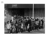
- FIG. 3 is a photograph explaining the situation at the time of the disaster. In the event of a disaster, people will line up to buy items as shown in FIG. If the arrival of water trucks is delayed, there is a problem that sufficient water cannot be supplied in an emergency.
- the present disclosure aims to provide utility poles that can supply rainwater to residents.
- the utility pole of the present disclosure has a water storage function inside the cylindrical structure, and is equipped with a drainage mechanism for the stored water.
- the utility pole of the present disclosure includes: A tubular structure with one end open and the other end closed, A drainage mechanism for discharging water inside the cylindrical structure is provided on the side surface of the other end.
- the utility pole of the present disclosure includes: At least part of the cylindrical structure is transparent.
- the utility pole of the present disclosure includes: The one end is provided with a cylindrical taper mechanism having an open end wider than the one end of the cylindrical structure.
- the utility pole of the present disclosure includes: The one end is provided with a filtration filter that prevents passage of solid matter.
- the utility pole of the present disclosure includes: A heating element is provided in the inner space of the cylindrical structure.
- the utility pole of the present disclosure includes:
- the drainage mechanism is characterized by comprising a purifying device for purifying water to be discharged.
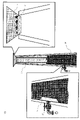
- FIG. 1 is a cross-sectional view of a utility pole in use;
- FIG. It is a figure explaining the erected utility pole. It is a photograph explaining the situation at the time of a disaster.
- It is a figure explaining the structure of the utility pole of this disclosure.
- It is a figure explaining the structure of the utility pole which can store water efficiently.
- It is a figure explaining the structure of the utility pole which can supply water sanitarily.
- FIG. 4 shows the structure of a utility pole with a water storage function.
- 10 is a utility pole
- 12 is a drainage mechanism
- 62 is rainwater.
- the top of a normal utility pole is covered with a cap. Without attaching the cap, one end of the utility pole 10 having a cylindrical structure is opened so that rainwater 62 can be conducted from the upper part of the utility pole 10. ⁇ The other end of the utility pole 10 on the ground side is closed. With this structure, when it rains, rainwater 62 enters inside the utility pole 10 and can be stored inside the utility pole 10 . The rainwater 62 may be directly guided to the inside of the utility pole 10 , or may be water-conducted to the inside of the utility pole 10 after being stored in one of them.
- a drainage mechanism 12 is provided on the side of the other end of the utility pole 10 .
- the drainage mechanism 12 drains water stored inside the utility pole 10 .
- a water faucet can be exemplified. When water is needed, the water inside the utility pole 10 can be taken out by turning the faucet.
- FIG. 5 shows a structure capable of efficiently storing water inside the utility pole 10 .
- 10 is a utility pole
- 13 is a taper mechanism
- 62 is rainwater.
- a cylindrical taper mechanism 13 may be provided at one end of the utility pole 10 . If one end of the taper mechanism 13 is an open end and is wider than the one end of the utility pole 10, that is, if it is inversely tapered, rain can be efficiently collected.
- FIG. 6 shows a structure capable of hygienically storing water inside the utility pole 10 and hygienically supplying water.
- 10 is a utility pole
- 12 is a drainage mechanism
- 13 is a taper mechanism
- 14 is a filtration filter
- 15 is a heating wire
- 16 is a purification device.
- one end of the utility pole 10 may be provided with a filtration filter 14 that blocks the passage of solid matter.
- the taper mechanism 13 may be provided with a filtration filter 14 that prevents passage of solid matter.
- the filtration filter 14 prevents animals and insects from entering the utility pole.
- a heating element may be provided in the internal space of the utility pole 10 . As shown in FIG. 6, the heating element can be exemplified by a heating wire 15 such as a nichrome wire.
- the heating element may be of any form as long as it can heat the stored water, as long as it generates heat. If an electric current is applied from the outside to heat the water, the stored water can be disinfected.
- the drainage mechanism 12 may be provided with a purification device 16 that purifies the water to be discharged.
- a purification device 16 that purifies the water to be discharged.
- water can be hygienically stored inside the utility pole 10 and discharged.
- the utility pole 10 may have a structure that allows confirmation of the amount of water stored inside.
- FIG. 7 shows a structure capable of confirming the amount of water stored inside the utility pole 10 .
- 10 is a utility pole.
- a general telephone pole cannot see the inside from the outside. Therefore, it is difficult to check the amount of stored water. Therefore, at least part of the utility pole 10 is made transparent.
- a portion is composed of acrylic, glass, or the like. The amount of water stored inside can be seen through the transparent portion.
- the entire utility pole 10 may be transparent.
- the transparent part may be window-shaped, or may be multiple window-shaped. If a transparent window is installed at a predetermined height, it is possible to visually check whether water is stored up to the predetermined height.
- the utility pole of the present disclosure can provide water to residents in an emergency.
- This disclosure can be applied to the information and communications industry.
Landscapes
- Engineering & Computer Science (AREA)
- Architecture (AREA)
- Environmental & Geological Engineering (AREA)
- Health & Medical Sciences (AREA)
- Life Sciences & Earth Sciences (AREA)
- Hydrology & Water Resources (AREA)
- Public Health (AREA)
- Water Supply & Treatment (AREA)
- Civil Engineering (AREA)
- Structural Engineering (AREA)
- Physical Water Treatments (AREA)
- Sewage (AREA)
Abstract
Description
一端が解放され、他端が閉鎖されている筒状構造で、
前記他端の側の側面に前記筒状構造の内部の水を排出する排水機構を備える。
前記筒状構造の少なくとも一部が透明であることを特徴とする。
前記一端に、前記筒状構造の一端よりも広い開放端を有する筒状のテーパ機構を備えることを特徴とする。
前記一端に、固形物の通過を阻止する濾過フィルタを備えることを特徴とする。
前記筒状構造の内部空間に発熱体を備えることを特徴とする。
前記排水機構は、排出する水を浄化する浄化装置を備えることを特徴とする。
電柱は、全国に3000万本以上設置され、電柱と電柱の間隔がおよそ30mである。この電柱に貯水できるシステムを付与する。貯水機能のある電柱の構造を図4に示す。図4において、10は電柱、12は排水機構、62は雨水である。
電柱10の内部に効率的に貯水できる構造を図5に示す。図5において、10は電柱、13はテーパ機構、62は雨水である。
電柱10の内部に衛生的に貯水でき、衛生的に給水できる構造を図6に示す。図6において、10は電柱、12は排水機構、13はテーパ機構、14は濾過フィルタ、15は電熱線、16は浄化装置である。
電柱10は、内部の貯水量を確認することができる構造を備えてもよい。電柱10の内部の貯水量を確認することができる構造を図7に示す。図7において、10は電柱である。一般的な電柱は外側から内部を見ることができない。そのため、貯水量を確認することが難しい。そこで、電柱10の少なくとも一部を透明とする。少なくとも一部を透明とするために、一部をアクリルやガラスなどで構成する。透明な部分を通して、内部の貯水量を目視することができる。電柱10の全体を透明としてもよい。
12:排水機構
13:テーパ機構
14:濾過フィルタ
15:電熱線
16:浄化装置
50:電柱
51:キャップ
52:コンクリート
53:鉄筋
54:電力ケーブル
55:電力ケーブル用金物
56:通信ケーブル
57:通信ケーブル用金物
60:地面
62:雨水
Claims (6)
- 一端が解放され、他端が閉鎖されている筒状構造で、
前記他端の側の側面に前記筒状構造の内部の水を排出する排水機構を備える電柱。 - 前記筒状構造の少なくとも一部が透明であることを特徴とする請求項1に記載の電柱。
- 前記一端に、前記筒状構造の一端よりも広い開放端を有する筒状のテーパ機構を備えることを特徴とする請求項1又は2に記載の電柱。
- 前記一端に、固形物の通過を阻止する濾過フィルタを備えることを特徴とする請求項1から3のいずれかに記載の電柱。
- 前記筒状構造の内部空間に発熱体を備えることを特徴とする請求項1から4のいずれかに記載の電柱。
- 前記排水機構は、排出する水を浄化する浄化装置を備えることを特徴とする請求項1から5のいずれかに記載の電柱。
Priority Applications (3)
| Application Number | Priority Date | Filing Date | Title |
|---|---|---|---|
| JP2023509905A JP7571861B2 (ja) | 2021-03-29 | 2021-03-29 | 電柱 |
| PCT/JP2021/013224 WO2022208591A1 (ja) | 2021-03-29 | 2021-03-29 | 電柱 |
| US18/281,758 US20240167294A1 (en) | 2021-03-29 | 2021-03-29 | Utility pole |
Applications Claiming Priority (1)
| Application Number | Priority Date | Filing Date | Title |
|---|---|---|---|
| PCT/JP2021/013224 WO2022208591A1 (ja) | 2021-03-29 | 2021-03-29 | 電柱 |
Publications (1)
| Publication Number | Publication Date |
|---|---|
| WO2022208591A1 true WO2022208591A1 (ja) | 2022-10-06 |
Family
ID=83458461
Family Applications (1)
| Application Number | Title | Priority Date | Filing Date |
|---|---|---|---|
| PCT/JP2021/013224 Ceased WO2022208591A1 (ja) | 2021-03-29 | 2021-03-29 | 電柱 |
Country Status (3)
| Country | Link |
|---|---|
| US (1) | US20240167294A1 (ja) |
| JP (1) | JP7571861B2 (ja) |
| WO (1) | WO2022208591A1 (ja) |
Citations (7)
| Publication number | Priority date | Publication date | Assignee | Title |
|---|---|---|---|---|
| JPS56156333A (en) * | 1980-05-02 | 1981-12-03 | Noboru Tatewada | Water gathering lid for water storing container |
| JPH0237946U (ja) * | 1988-09-05 | 1990-03-13 | ||
| JPH0947765A (ja) * | 1995-08-09 | 1997-02-18 | Suido Kiko Kaisha Ltd | 雨水処理ユニットおよび雨水浄化貯留装置 |
| JPH11122765A (ja) * | 1997-10-09 | 1999-04-30 | Furukawa Electric Co Ltd:The | 発熱性ユニット収納電柱構造体 |
| JP2010203101A (ja) * | 2009-03-02 | 2010-09-16 | Hiroyasu Minayoshi | 水抜栓およびこの水抜栓を用いた水抜処理方法 |
| JP3194512U (ja) * | 2014-09-16 | 2014-11-27 | 綿半鋼機株式会社 | パイプ式ブレース材 |
| JP2019152100A (ja) * | 2019-06-25 | 2019-09-12 | 綿半ソリューションズ株式会社 | 雨水貯留機能付コラム柱 |
Family Cites Families (6)
| Publication number | Priority date | Publication date | Assignee | Title |
|---|---|---|---|---|
| FR2714409B1 (fr) * | 1993-12-23 | 1996-03-15 | Cogidev | Structure porteuse pouvant être utilisée comme poteau ou poutre. |
| US9604857B2 (en) * | 2014-03-11 | 2017-03-28 | Basic Co., Ltd. | Water purifier |
| US20170174090A1 (en) * | 2015-12-18 | 2017-06-22 | Totem Power, Inc. | Smart utility tower |
| US10704235B2 (en) * | 2015-12-21 | 2020-07-07 | Andre Green | System and method for harvesting rainwater |
| CN207124289U (zh) * | 2017-07-13 | 2018-03-20 | 苏炎杰 | 一种可收集雨水资源再利用的雷达信号通讯天线 |
| CN109058867B (zh) * | 2018-07-19 | 2020-09-18 | 扬州市杰耀照明器材有限公司 | 一种浮动式环保集雨路灯 |
-
2021
- 2021-03-29 US US18/281,758 patent/US20240167294A1/en not_active Abandoned
- 2021-03-29 WO PCT/JP2021/013224 patent/WO2022208591A1/ja not_active Ceased
- 2021-03-29 JP JP2023509905A patent/JP7571861B2/ja active Active
Patent Citations (7)
| Publication number | Priority date | Publication date | Assignee | Title |
|---|---|---|---|---|
| JPS56156333A (en) * | 1980-05-02 | 1981-12-03 | Noboru Tatewada | Water gathering lid for water storing container |
| JPH0237946U (ja) * | 1988-09-05 | 1990-03-13 | ||
| JPH0947765A (ja) * | 1995-08-09 | 1997-02-18 | Suido Kiko Kaisha Ltd | 雨水処理ユニットおよび雨水浄化貯留装置 |
| JPH11122765A (ja) * | 1997-10-09 | 1999-04-30 | Furukawa Electric Co Ltd:The | 発熱性ユニット収納電柱構造体 |
| JP2010203101A (ja) * | 2009-03-02 | 2010-09-16 | Hiroyasu Minayoshi | 水抜栓およびこの水抜栓を用いた水抜処理方法 |
| JP3194512U (ja) * | 2014-09-16 | 2014-11-27 | 綿半鋼機株式会社 | パイプ式ブレース材 |
| JP2019152100A (ja) * | 2019-06-25 | 2019-09-12 | 綿半ソリューションズ株式会社 | 雨水貯留機能付コラム柱 |
Also Published As
| Publication number | Publication date |
|---|---|
| JPWO2022208591A1 (ja) | 2022-10-06 |
| US20240167294A1 (en) | 2024-05-23 |
| JP7571861B2 (ja) | 2024-10-23 |
Similar Documents
| Publication | Publication Date | Title |
|---|---|---|
| Acevedo-Guerrero | Light is like water: flooding, blackouts, and the state in Barranquilla | |
| Glaas et al. | The 2021 extreme rainfall in Gävle, Sweden: Impacts on municipal welfare services and actions towards more resilient premises and operations | |
| Sameen | Process inclusive infrastructure: notions towards cyclone resilience in Bangladesh | |
| WO2022208591A1 (ja) | 電柱 | |
| Siyongwana et al. | The vulnerability of low-income communities to flood hazards, missionvale, South Africa | |
| Albanese et al. | Informal Housing of Migrants in Italy | |
| DE102010049122A1 (de) | Schutz- und Notraum für den Einsatz in Krisen- und Katastrophengebieten | |
| Bello et al. | Assessment of the Effects and Impacts of Hurricane Matthew, The Bahamas | |
| Kifworo et al. | Hailstorms damage and resilience-building in South Africa’s key tourism destinations and attractions | |
| Blom et al. | Smart shelter strategies; cost-effective flood preparedness | |
| Brunsdon | Critical infrastructure and earthquakes: Understanding the essential elements of disaster management | |
| Szilvasi et al. | The struggle for the right to water for Roma in France | |
| JP6468726B2 (ja) | 仮設トイレ収容型地下貯蔵槽 | |
| CN205614245U (zh) | 一种简易自制止水螺杆焊接定位件 | |
| Garg et al. | Atmanirbharta—the Journey from Disaster to Human Resilience | |
| Smith | Cedar rapids flood buyout is history | |
| Islam et al. | Urban land use in Narayanganj: dominance of economic activities, squeezed for social space | |
| Murphy et al. | Massachusetts Homeowner's Handbook To Prepare For Coastal Hazards (July 2020) | |
| Berman et al. | Massachusetts Homeowner's Handbook to Prepare for Coastal Hazards | |
| Oka | An Enquiry into Spatial Attributes of the Urban: Rural Transients in India | |
| Shilpakar et al. | Relocation of Monuments in Kwelachhi of Lubhu | |
| Carey et al. | Delaware Homeowners Handbook To Prepare For Natural Hazards, August 2019 | |
| Hwang et al. | Homeowner's handbook to prepare for natural hazards | |
| Szilvasi | Separate, Unequal, and Hazardous: The Essential Guide to Roma Housing in Slovakia | |
| Rukesh Reddy et al. | Rainwater harvesting in hostels 12 and 13 of IIT bombay |
Legal Events
| Date | Code | Title | Description |
|---|---|---|---|
| 121 | Ep: the epo has been informed by wipo that ep was designated in this application |
Ref document number: 21934767 Country of ref document: EP Kind code of ref document: A1 |
|
| ENP | Entry into the national phase |
Ref document number: 2023509905 Country of ref document: JP Kind code of ref document: A |
|
| WWE | Wipo information: entry into national phase |
Ref document number: 18281758 Country of ref document: US |
|
| NENP | Non-entry into the national phase |
Ref country code: DE |
|
| 122 | Ep: pct application non-entry in european phase |
Ref document number: 21934767 Country of ref document: EP Kind code of ref document: A1 |