WO2022208573A1 - 圧縮機 - Google Patents
圧縮機 Download PDFInfo
- Publication number
- WO2022208573A1 WO2022208573A1 PCT/JP2021/013194 JP2021013194W WO2022208573A1 WO 2022208573 A1 WO2022208573 A1 WO 2022208573A1 JP 2021013194 W JP2021013194 W JP 2021013194W WO 2022208573 A1 WO2022208573 A1 WO 2022208573A1
- Authority
- WO
- WIPO (PCT)
- Prior art keywords
- wall
- main shaft
- oil
- refrigerant
- container
- Prior art date
- Legal status (The legal status is an assumption and is not a legal conclusion. Google has not performed a legal analysis and makes no representation as to the accuracy of the status listed.)
- Ceased
Links
Images


Classifications
-
- F—MECHANICAL ENGINEERING; LIGHTING; HEATING; WEAPONS; BLASTING
- F04—POSITIVE - DISPLACEMENT MACHINES FOR LIQUIDS; PUMPS FOR LIQUIDS OR ELASTIC FLUIDS
- F04B—POSITIVE-DISPLACEMENT MACHINES FOR LIQUIDS; PUMPS
- F04B39/00—Component parts, details, or accessories, of pumps or pumping systems specially adapted for elastic fluids, not otherwise provided for in, or of interest apart from, groups F04B25/00 - F04B37/00
- F04B39/02—Lubrication
-
- F—MECHANICAL ENGINEERING; LIGHTING; HEATING; WEAPONS; BLASTING
- F04—POSITIVE - DISPLACEMENT MACHINES FOR LIQUIDS; PUMPS FOR LIQUIDS OR ELASTIC FLUIDS
- F04C—ROTARY-PISTON, OR OSCILLATING-PISTON, POSITIVE-DISPLACEMENT MACHINES FOR LIQUIDS; ROTARY-PISTON, OR OSCILLATING-PISTON, POSITIVE-DISPLACEMENT PUMPS
- F04C18/00—Rotary-piston pumps specially adapted for elastic fluids
- F04C18/02—Rotary-piston pumps specially adapted for elastic fluids of arcuate-engagement type, i.e. with circular translatory movement of co-operating members, each member having the same number of teeth or tooth-equivalents
-
- F—MECHANICAL ENGINEERING; LIGHTING; HEATING; WEAPONS; BLASTING
- F04—POSITIVE - DISPLACEMENT MACHINES FOR LIQUIDS; PUMPS FOR LIQUIDS OR ELASTIC FLUIDS
- F04C—ROTARY-PISTON, OR OSCILLATING-PISTON, POSITIVE-DISPLACEMENT MACHINES FOR LIQUIDS; ROTARY-PISTON, OR OSCILLATING-PISTON, POSITIVE-DISPLACEMENT PUMPS
- F04C29/00—Component parts, details or accessories of pumps or pumping installations, not provided for in groups F04C18/00 - F04C28/00
- F04C29/02—Lubrication; Lubricant separation
Definitions
- the present disclosure relates to a compressor that compresses refrigerant.
- scroll compressors for refrigeration or air conditioning applications have been known as compressors for compressing refrigerant.
- a scroll compressor compresses refrigerant by orbiting the orbiting scroll in a compression unit that is a combination of a fixed scroll and an orbiting scroll each provided with a spiral projection.
- Refrigerant is compressed in a compression chamber formed by meshing spiral projections.
- the compressor rotates a shaft supported by two bearings, a main bearing and a sub-bearing, by an electric motor unit in order to orbit the orbiting scroll smoothly.
- Patent Literature 1 discloses a scroll compressor in which a mesh is provided as an oil filter in an oil pumping path of an oil pump. Patent Literature 1 intends to prevent foreign matter from entering the refrigerating machine oil that is sucked up to the bearing.
- the present disclosure has been made to solve the problems described above, and provides a compressor that sufficiently prevents foreign matter from entering the refrigerating machine oil.
- a compressor includes a container that forms an outer shell and has a bottom portion in which an oil reservoir is formed, an electric motor unit provided inside the container, and a main shaft that is attached to the electric motor unit and transmits the rotational force of the electric motor unit. , a compression unit that rotates with the rotation of the main shaft to compress the refrigerant, and a wall provided around a portion at the bottom where the refrigerating machine oil is sucked up from the oil reservoir.
- a wall is provided around the part where oil is sucked up from the oil pool.
- the wall catches any foreign matter trying to reach the bottom side of the container. Therefore, it is possible to sufficiently prevent foreign matter from entering the refrigerating machine oil.
- FIG. 1 is a circuit diagram showing a refrigeration cycle device according to Embodiment 1 of the present disclosure
- FIG. 1 is a cross-sectional view showing a compressor according to Embodiment 1 of the present disclosure
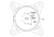
- FIG. Fig. 2 is a diagram showing a wall according to Embodiment 1 of the present disclosure
- FIG. 10 is a diagram showing a wall according to the first modification of the first embodiment of the present disclosure
- FIG. FIG. 10 is a diagram showing a wall according to a second modification of the first embodiment of the present disclosure
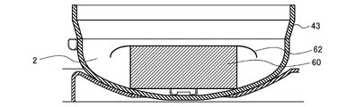
- FIG. FIG. 10 is a diagram showing a wall according to a third modification of the first embodiment of the present disclosure
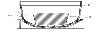
- FIG. FIG. 13 is a diagram showing a wall according to a fourth modification of the first embodiment of the present disclosure
- FIG. 1 is a circuit diagram showing a refrigeration cycle device 1 according to Embodiment 1 of the present disclosure.
- the refrigeration cycle device 1 is, for example, a device that adjusts indoor air, and includes an outdoor unit 1a, an indoor unit 1b, and a control device 70, as shown in FIG.
- the outdoor unit 1a is provided with, for example, a compressor 100, an outdoor heat exchanger 200, an outdoor fan 201, an expansion section 300, and an intermediate injection circuit 800.
- the indoor unit 1b is provided with an indoor heat exchanger 400 and an indoor fan 401, for example.
- a refrigerant circuit 500 is configured by connecting the compressor 100 , the outdoor heat exchanger 200 , the expansion section 300 and the indoor heat exchanger 400 by a refrigerant pipe 501 .
- the compressor 100 is a scroll compressor that draws in low-temperature, low-pressure refrigerant, compresses the drawn-in refrigerant, and discharges the high-temperature, high-pressure refrigerant.
- the outdoor heat exchanger 200 exchanges heat between a high-temperature, high-pressure gaseous refrigerant flowing inside the outdoor heat exchanger 200 and a low-temperature medium passing through the outdoor heat exchanger 200 .
- the outdoor heat exchanger 200 is, for example, an air-cooled heat exchanger that exchanges heat between low-temperature outdoor air and a refrigerant.
- the outdoor heat exchanger 200 acts as a condenser.
- the outdoor fan 201 is a device that sends outdoor air to the outdoor heat exchanger 200 .
- the expansion section 300 is a pressure reducing valve or an expansion valve that reduces the pressure of a high-pressure liquid refrigerant to expand it.
- the expansion section 300 is, for example, an expander, a thermostatic automatic expansion valve, or a linear electronic expansion valve whose opening is adjusted.
- the indoor heat exchanger 400 exchanges heat between a low-temperature, low-pressure liquid refrigerant or gas-liquid two-phase refrigerant flowing inside the indoor heat exchanger 400 and a high-temperature medium passing through the indoor heat exchanger 400. It is something to do.
- the indoor heat exchanger 400 is, for example, an air-cooled heat exchanger that exchanges heat between high-temperature indoor air and refrigerant.
- Indoor heat exchanger 400 acts as an evaporator.
- the indoor fan 401 is a device that sends indoor air to the indoor heat exchanger 400 .
- the intermediate injection circuit 800 connects between the outdoor heat exchanger 200 and the expansion section 300 and the injection pipe 49 of the compressor 100 . Refrigerant flowing out of the outdoor heat exchanger 200 flows through the intermediate injection circuit 800 .
- Intermediate injection circuit 800 is provided with injection expansion section 600 and cooler 700 .
- the intermediate injection circuit 800 is provided to introduce a low-temperature, low-pressure liquid refrigerant or gas-liquid two-phase refrigerant into the compression unit 10 of the compressor 100 .
- the injection expansion section 600 is, like the expansion section 300, a decompression valve or an expansion valve that decompresses and expands the high-pressure liquid refrigerant flowing through the intermediate injection circuit 800.
- the injection expansion section 600 is, for example, an expander, a thermostatic automatic expansion valve, or a linear electronic expansion valve whose opening is adjusted.
- the cooler 700 exchanges heat between a low-temperature, low-pressure liquid refrigerant or gas-liquid two-phase refrigerant flowing inside the cooler 700 and a high-temperature medium passing through the cooler 700 .
- Cooler 700 is, for example, an air-cooled heat exchanger that exchanges heat between high-temperature indoor air and a refrigerant. Note that the cooler 700 may be a double-tube supercooling heat exchanger.
- the low-temperature and low-pressure gas-liquid two-phase refrigerant that flows out from the injection expansion unit 600 and flows inside the cooler 700 and the high-pressure liquid refrigerant that flows out from the outdoor heat exchanger 200 or the gas-liquid two-phase state heat is exchanged with the refrigerant of Also, the cooler 700 may be omitted from the injection circuit.
- the control device 70 is composed of, for example, a microcomputer and memory, and controls each device of the refrigeration cycle device 1 .
- the control device 70 adjusts the opening degree of the injection expansion section 600 to adjust the amount of refrigerant flowing through the intermediate injection circuit 800 .
- a fluorocarbon refrigerant such as R32 or a natural refrigerant such as carbon dioxide (CO 2 ) is used as the refrigerant.
- FIG. 2 is a cross-sectional view showing compressor 100 according to Embodiment 1 of the present disclosure.
- the compressor 100 sucks and compresses the refrigerant circulating in the refrigerant circuit 500, for example, and discharges the refrigerant in a high-temperature and high-pressure state, and is, for example, a hermetic scroll compressor.
- Compressor 100 as shown in FIG. a unit 10;
- the compressor 100 also includes a boss portion 27, an Oldham ring 22a, a sleeve 34, a discharge valve 5, a valve guard 6, a discharge muffler 7, an oil pump 51, an oil drain pipe 50, and an electric motor unit 30. and a wall 60.
- the container 40 is a closed container that constitutes the outer shell of the compressor 100 and has a cylindrical shape. Inside the container 40, the compression unit 10, the electric motor unit 30 and other parts are accommodated. Inside the container 40, the compression unit 10 is arranged above and the electric motor unit 30 is arranged below.
- the container 40 has a bottom portion 43 , a body portion 42 and a lid portion 41 .
- the bottom portion 43 is a dish-shaped member in which the oil reservoir 2 that stores the refrigerator oil is formed.
- the trunk portion 42 is a bottomed cylindrical member extending upward from the bottom portion 43 .
- a suction pipe 44 for sucking the low-pressure refrigerant flowing out of the indoor heat exchanger 400 is connected to the body portion 42 .
- the lid portion 41 is a dome-shaped member provided on the upper portion of the body portion 42 .
- a discharge pipe 45 for discharging high-pressure refrigerant is connected to the lid portion 41 .
- the frame 46 is fixed to the container 40, accommodates the compression unit 10, and rotatably supports the main shaft 33 via, for example, a main bearing 46a.
- the frame 46 is arranged above the electric motor unit 30 and positioned between the electric motor unit 30 and the compression unit 10 .
- a plurality of intake ports 36 are formed in the frame 46 , and refrigerant flows into the compression unit 10 through the plurality of intake ports 36 .
- the plurality of intake ports 36 are located between the space within the container 40 between the frame 46 and the electric motor unit 30 and the space outside the contours of the first spiral tooth 24 and the second spiral tooth 26 in the compression unit 10. is a through hole that connects A space in the container 40 between the frame 46 and the electric motor unit 30 is connected to a suction pipe 44 .
- the subframe 47 is arranged below the electric motor unit 30 inside the container 40 .
- the subframe 47 rotatably supports the main shaft 33 via a subbearing 48 .
- a hole 47 a is formed in the sub-frame 47 . Refrigerating machine oil flowing down toward the oil sump 2 passes through the hole 47a.
- the frame 46 and the sub-frame 47 are fixed inside the container 40 so as to face each other with the electric motor unit 30 interposed therebetween.
- the frame 46 and the sub-frame 47 are fixed to the inner peripheral surface of the body portion 42 of the container 40 by shrink fitting, welding, or the like.
- the main shaft 33 is a rod-shaped crankshaft that is supported by the frame 46 in the center of the container 40 and extends vertically, and connects the electric motor unit 30 and the compression unit 10 .
- the main shaft 33 connects the electric motor unit 30 and the compression unit 10 to transmit the rotational force of the electric motor unit 30 to the compression unit 10 .
- the main shaft 33 has an eccentric shaft portion 33a, a main shaft portion 33b, and a sub shaft portion 33c.
- the eccentric shaft portion 33a is eccentric with respect to the axis of the main shaft 33 and is rotatably accommodated in the rocking bearing 27a.
- the outer peripheral portion of the eccentric shaft portion 33a is in close contact with the inner peripheral portion of the swing bearing 27a via the refrigerator oil.
- the main shaft portion 33b is supported by a main bearing 46a provided on the frame 46. As shown in FIG. A sleeve 34 is provided between the main bearing 46a and the main shaft portion 33b.
- the secondary shaft portion 33c is rotatably supported by a secondary bearing 48.
- a secondary bearing 48 As shown in FIG. 33 d of oil passages through which oil flows are formed in the inside of the main shaft 33.
- the main bearing 46a is provided in the central portion of the frame 46 and supports the upper portion of the main shaft 33 so as to be rotatable.
- the sub-bearing 48 is press-fitted into the central portion of the sub-frame 47 and supports the lower portion of the main shaft 33 rotatably.
- the secondary bearing 48 is, for example, a ball bearing.
- the intake pipe 44 is connected to the low pressure space 8 formed between the electric motor unit 30 and the compression unit 10 in the container 40 at the side of the container 40 .
- the suction pipe 44 sucks the low-pressure refrigerant flowing from the refrigerant pipe 501 into the low-pressure space 8 .
- the discharge pipe 45 is connected to the high pressure space 9 formed above the compression unit 10 in the container 40 at the top of the container 40 .
- the discharge pipe 45 discharges the high-pressure refrigerant compressed by the compression unit 10 to the refrigerant pipe 501 outside the compressor 100 .
- the injection pipe 49 is connected to the compression chamber 11 of the compression unit 10 above the container 40 .
- the injection pipe 49 introduces the liquid or gas-liquid two-phase refrigerant flowing through the intermediate injection circuit 800 into the compression chamber 11 .
- the injection pipe 49 is provided in the container 40 and introduces the refrigerant in a liquid state or a gas-liquid two-phase state into the compression unit 10 .
- the compression chamber 11 has a suction chamber 12 connected to the suction port 36 and a discharge chamber 13 connected to the discharge port 3 .
- the compression unit 10 compresses the refrigerant sucked from the suction pipe 44 and discharges it to the high-pressure space 9 formed inside and above the container 40 .
- the compression unit 10 has a fixed scroll 21 and an orbiting scroll 22 .
- the fixed scroll 21 is fixed to the container 40 via a frame 46 above the orbiting scroll 22 and has a first base plate 23 and first spiral teeth 24 .
- the first base plate 23 is a plate-like member and constitutes the upper surface of the compression unit 10 .
- the first spiral tooth 24 is a spiral protrusion extending downward from the lower surface of the first base plate 23 .
- the orbiting scroll 22 has a second base plate 25 and second spiral teeth 26 .
- the second base plate 25 is a plate-like member arranged above the frame 46 .
- the second spiral tooth 26 is a spiral protrusion extending upward from the upper surface of the second base plate 25 .
- the fixed scroll 21 and the orbiting scroll 22 are provided in the container 40 with the first spiral tooth 24 and the second spiral tooth 26 meshing with each other.
- the first spiral tooth 24 and the second spiral tooth 26 are formed following an involute curve.
- a plurality of compression chambers 11 are formed between the second spiral tooth 26 and the second spiral tooth 26 .
- a discharge port 3 which is a space through which compressed and high-pressure refrigerant is discharged, is formed in the central portion of the fixed scroll 21.
- An injection pipe insertion port 28 to which an injection pipe 49 is connected is formed in the first base plate 23 of the fixed scroll 21 .
- the liquid or gas-liquid two-phase refrigerant flowing from the injection pipe 49 flows out through the injection port 16 into the compression chamber 11 where the refrigerant is in the middle of the compression process.
- the boss portion 27 is provided at the center of the surface of the second base plate 25 opposite to the surface on which the second spiral teeth 26 are formed, and has a hollow cylindrical shape.
- a swing bearing 27 a is provided between the swing scroll 22 and the boss portion 27 .
- the swing bearing 27a covers the main shaft 33 and the eccentric shaft portion 33a, and supports the main shaft 33 so as to be rotatable.
- the eccentric shaft portion 33 a is provided at the upper end of the main shaft 33 and rotates the orbiting scroll 22 eccentrically.
- the Oldham ring 22a is provided on the thrust surface opposite to the surface of the orbiting scroll 22 on which the second spiral teeth 26 are formed. The Oldham's ring 22a prevents the orbiting scroll 22 from rotating during the eccentric orbiting motion, and allows the orbiting scroll 22 to revolve.
- the upper and lower surfaces of the Oldham's ring 22a are provided with claws (not shown) projecting perpendicularly to each other.
- the claws of the Oldham ring 22a are inserted into Oldham grooves (not shown) formed in the orbiting scroll 22 and the frame 46. As shown in FIG.
- the sleeve 34 is a cylindrical member provided between the frame 46 and the main bearing 46a, and absorbs the tilted state between the frame 46 and the main shaft 33.
- the discharge valve 5 is a plate spring member that covers the discharge port 3 and prevents the refrigerant from flowing backward.
- the refrigerant When the refrigerant is compressed to a predetermined pressure in the compression chamber 11 , the refrigerant lifts the discharge valve 5 against the elastic force of the discharge valve 5 .
- the compressed refrigerant is then discharged from the discharge port 3 into the high-pressure space 9 and discharged outside the compressor 100 through the discharge pipe 45 .
- the valve guard 6 regulates the movable range of the discharge valve 5 .
- the discharge muffler 7 covers the discharge valve 5 and suppresses pulsation of the refrigerant discharged from the discharge port 3 .
- the oil pump 51 is accommodated in the bottom portion 43 of the container 40 and sucks up oil from the oil reservoir 2.
- the oil pump 51 is fixed to the lower portion of the main shaft 33 .
- the oil pump 51 sucks up the oil stored in the oil sump 2 into an oil passage 33d formed inside the main shaft 33, and supplies the oil to the auxiliary bearing 48, the main bearing 46a and the oscillating bearing 27a through the oil passage 33d.
- the oil pump 51 may be omitted. In this case, for example, a configuration is adopted in which the oil is sucked up from the oil sump 2 using differential pressure.
- the oil drain pipe 50 is a pipe that connects the space between the frame 46 and the orbiting scroll 22 and the space between the frame 46 and the subframe 47 .
- the oil drain pipe 50 drains excessive oil out of the oil flowing in the space between the frame 46 and the orbiting scroll 22 to the space between the frame 46 and the sub-frame 47 .
- the oil that has flowed out into the space between the frame 46 and the subframe 47 passes through the subframe 47 and returns to the oil reservoir 2 .
- the motor unit 30 is provided inside the container 40 in the low-pressure space 8 on the low-pressure side into which the refrigerant is sucked.
- the electric motor unit 30 drives the orbiting scroll 22 that constitutes the compression unit 10 . That is, the electric motor unit 30 rotates the orbiting scroll 22 via the main shaft 33 to compress the refrigerant in the compression unit 10 .
- the electric motor unit 30 has a rotor 32 and a stator 31 .
- the rotor 32 is provided on the inner peripheral side of the stator 31 . When the stator 31 is energized, the rotor 32 is rotationally driven to rotate the main shaft 33 .
- the rotor 32 is fixed to the outer circumference of the main shaft 33 and held with a small gap from the stator 31 .
- the low-pressure refrigerant flowing out of the indoor heat exchanger 400 is sucked into the low-pressure space 8 of the container 40 through the suction pipe 44, and flows between the first spiral teeth 24 of the fixed scroll 21 and the second spiral teeth 26 of the orbiting scroll 22. It is taken into the suction chamber 12 on the outer peripheral side of the plurality of compression chambers 11 formed in the . As the orbiting scroll 22 eccentrically revolves, the compression chamber 11 that takes in the refrigerant reduces its volume while moving from the outer circumference to the center, thereby compressing the refrigerant.
- the compressed refrigerant is discharged from the discharge chamber 13 through the discharge port 3 formed in the fixed scroll 21 against the valve guard 6 into the high-pressure space 9 , and then discharged out of the container 40 through the discharge pipe 45 via the discharge muffler 7 . be done.
- the high pressure refrigerant discharged from the discharge pipe 45 flows into the outdoor heat exchanger 200 .
- part of the refrigerant sucked from the suction pipe 44 flows into the frame 46 through the suction port 36 of the frame 46 and is sucked into the compression unit 10 .
- the coolant that has not flowed into the frame 46 cools the electric motor unit 30 and the oil pool 2 .
- the refrigerant sucked into the compression unit 10 is mixed with the refrigerant flowing from the injection pipe 49, so that the temperature of the refrigerant sucked into the compression unit 10 is lowered. Therefore, since the thermal expansion of the fixed scroll 21 and the orbiting scroll 22 can be suppressed, the behavior of the compression unit 10 can be stabilized.
- the refrigerant sucked into the compressor 100 is compressed by the compressor 100 and discharged in a high-temperature and high-pressure gas state.
- the high-temperature and high-pressure gaseous refrigerant discharged from the compressor 100 flows into the outdoor heat exchanger 200 acting as a condenser, where it is heat-exchanged with the outdoor air sent by the outdoor blower 201. condensed and liquefied.
- the condensed liquid refrigerant flows into the expansion section 300 and is expanded and decompressed in the expansion section 300 to become a low-temperature, low-pressure gas-liquid two-phase refrigerant.
- the gas-liquid two-phase refrigerant flows into the indoor heat exchanger 400 acting as an evaporator, and in the indoor heat exchanger 400, heat is exchanged with the indoor air sent by the indoor blower 401 to evaporate and gasify. do.
- the indoor air is cooled, and cooling is performed in the room.
- the vaporized low-temperature, low-pressure gaseous refrigerant is sucked into the compressor 100 .
- the temperature of the refrigerant discharged from the discharge pipe 45 is high.
- the operation with a large difference between the intake temperature and the discharge temperature means high compression ratio operation with a large differential pressure between the high pressure and the low pressure.
- the liquid state or gas-liquid two-phase refrigerant flowing to the outlet side of the outdoor heat exchanger 200 is injected into the compression chamber 11 of the compressor 100, thereby lowering the discharge temperature.
- the high-pressure refrigerant flowing out of the outdoor heat exchanger 200 is decompressed to an intermediate pressure with the throttle expansion rate and flow rate controlled by the injection expansion section 600 .
- the liquid state refrigerant decompressed to the intermediate pressure flows into the compressor 100 from the injection pipe 49 .
- the liquid state refrigerant that has flowed into the compressor 100 is injected into the compression chamber 11 from the injection pipe insertion port 28 .
- the refrigerant in the liquid state cools the refrigerant in the gaseous state during compression in the compression chamber 11 .
- a magnet (not shown) is provided at the center of the bottom portion 43 of the container 40 , and a cylindrical wall 60 is provided to surround the center of the bottom portion 43 of the container 40 .
- the wall 60 is secured to the bottom 43 of the container 40, such as by welding.
- the wall 60 functions as a bank.
- the wall 60 receives foreign matter such as copper when brazing the refrigerant pipe 501 or iron powder when assembling the refrigerating cycle device 1 from the suction pipe 44 . As a result, foreign matter can be prevented from entering the oil reservoir 2 on the bottom portion 43 of the container 40 .
- the wall 60 is not limited to a cylindrical shape, and may have a plurality of arcuate small walls 60a (not shown) arranged concentrically. Moreover, the wall 60 may have a plurality of small walls 60a with different heights.
- the foreign matter is, for example, alumina (AlO 2 ), and includes not only those generated inside the compressor 100 but also those existing inside the refrigeration cycle apparatus 1 and flowing into the compressor 100 . It also includes metal powder generated by metal sliding in the compressor 100 .
- FIG. 3 is a diagram showing the wall 60 according to Embodiment 1 of the present disclosure.
- ⁇ df is twice the distance from the center of the main shaft 33 to the wall 60
- ⁇ dop is twice the distance from the center of the main shaft 33 to the outer shape of the oil pump 51
- the center of the main shaft 33 to the hole 47a of the subframe 47 is ⁇ dsb is twice the distance of .
- the relationship ⁇ dop ⁇ df ⁇ dsb is established.
- a wall 60 is provided around the portion where oil is sucked up from the oil reservoir 2 . For this reason, the wall 60 catches the foreign matter trying to reach the bottom portion 43 side of the container 40 in which the oil pump 51 is provided. Therefore, it is possible to sufficiently prevent foreign matter from entering the refrigerating machine oil.
- FIG. 4 is a diagram showing the wall 60 according to the first modification of the first embodiment of the present disclosure.
- the wall 60 is formed with an opening, and the opening is provided with a mesh 61 .
- the mesh 61 has, for example, an opening of 50 ⁇ m to 80 ⁇ m.
- the mesh 61 used has a finer mesh than that provided in the oil pump 51 .
- the mesh size of the oil pump 51 is 100
- the mesh size of the wall 60 is 200.
- the mesh size of the mesh 61 provided in the opening of the wall 60 can be appropriately changed according to the size of the foreign matter to be captured. For example, when the wear of the bearing of the compressor 100 returned from a certain area is caused by foreign matter of 50 ⁇ m, the mesh 61 with a mesh size of 325 is used. As a result, foreign matter can be received by the wall 60 , and only the refrigerating machine oil and foreign matter of 50 ⁇ m or less are stored in the center of the bottom portion 43 of the container 40 . Therefore, it is possible to suppress wear of the bearings of the compressor 100 used in that area. In this manner, wear of the bearing portion can be suppressed in each model simply by changing the mesh size for each model.
- the height of the wall 60 is equal to or higher than the lower end of the mesh 61 of the oil pump 51 .
- the height of the wall 60 is positioned in a range equal to or higher than the lower end of the mesh 61 of the oil pump 51 and equal to or lower than the lower end of the sub-frame 47 .
- FIG. 5 is a diagram showing a wall 60 according to a second modification of Embodiment 1 of the present disclosure.
- the walls 60 are provided so as to face each other between the portions where the subframes 47 are shrink-fitted.
- the wall 60 has a semi-cylindrical shape.
- the portion where the subframe 47 is shrink-fitted is the portion indicated by the white arrow in FIG.
- the wall 60 is provided under the gap between the shrink-fitted portions of the subframe 47 .
- the wall 60 catches the foreign matter and prevents the foreign matter from entering the center of the bottom portion 43 of the container 40 . In this manner, depending on the shape of the wall 60 and the position where the wall 60 is installed, it is possible to facilitate trapping foreign matter.
- FIG. 6 is a diagram showing a wall 60 according to a third modified example of Embodiment 1 of the present disclosure. Next, the 3rd modification is demonstrated.
- the wall 60 has a roll-up preventing portion 62 provided at the upper end portion for receiving foreign matter contained in the refrigerating machine oil that has been lifted up by the oil pump 51 .
- the roll-up preventing portion 62 can receive the rolled-up foreign matter and accumulate the foreign matter between the wall 60 and the bottom portion 43 of the container 40 .
- FIG. 7 is a diagram showing a wall 60 according to a fourth modified example of Embodiment 1 of the present disclosure.
- the wall 60 is slanted from the outside to the inside, from the top end to the bottom end. Since the bottom 43 of the container 40 is dish-shaped, it slopes downward toward the center. As described above, since the wall 60 is inclined, foreign matter is collected on the bottom portion 43 side of the wall 60 . As a result, even if the refrigerating machine oil is agitated by the oil pump 51, it is possible to suppress flying foreign matter. Note that even if the wall 60 stands upright, the same effect as in the fourth modified example can be obtained if a foreign object pocket cut in the center direction is provided on the bottom 43 side of the wall 60 .
- the compressor 100 can be modified as appropriate. It should be noted that the first to fourth modifications described above can be combined with each other. Also, for example, in the above-described embodiment, the compressor 100 has one compression unit 10 , but a plurality of compression units 10 may be provided. Further, in FIG. 2, the compressor 100 is illustrated as being of a closed type, but it may be of an open type or a semi-closed type.
Landscapes
- Engineering & Computer Science (AREA)
- Mechanical Engineering (AREA)
- General Engineering & Computer Science (AREA)
- Applications Or Details Of Rotary Compressors (AREA)
Abstract
圧縮機は、外郭を構成し、油溜まりが形成された底部を有する容器と、容器の内部に設けられる電動機ユニットと、電動機ユニットに取り付けられ、電動機ユニットの回転力を伝達する主軸と、主軸の回転に伴って回転して冷媒を圧縮する圧縮ユニットと、底部において、油溜まりから冷凍機油が吸い上げられる部分の周囲に設けられる壁と、を備える。
Description
本開示は、冷媒を圧縮する圧縮機に関する。
従来、冷媒を圧縮する圧縮機として、冷凍用途又は空調用途等のスクロール圧縮機が知られている。スクロール圧縮機は、渦巻状の突起がそれぞれ設けられた固定スクロールと揺動スクロールとを組み合わせた圧縮ユニットにおいて、揺動スクロールを旋回することによって、冷媒を圧縮する。冷媒は、渦巻状の突起同士が噛み合わされて構成された圧縮室において圧縮される。圧縮機は、揺動スクロールを円滑に旋回するために、主軸受及び副軸受という2個の軸受によって支持された軸部を、電動機ユニットによって回転している。
スクロール圧縮機は、密閉された容器の底部に溜められた冷凍機油に、配管ロウ付け時の銅、又は圧縮機が組み立てられる際の鉄粉等の異物が混入するおそれがある。そして、異物は、油ポンプによって軸受まで吸い上げられ、軸受を損傷させて故障させるおそれがある。これを解決するために、従来、圧縮機の容器の底部にマグネットが取り付けられ、磁性を有する異物をマグネットに吸着させる技術が知られている。また、特許文献1には、油ポンプによる油汲み上げ経路に、油フィルターとしてメッシュを設けたスクロール圧縮機が開示されている。特許文献1は、これにより、軸受まで吸い上げられる冷凍機油内に、異物が混入することを抑制しようとするものである。
しかしながら、圧縮機の容器の底部にマグネットが取り付けられた従来技術では、磁性を有しない異物を捕捉することはできない。また、特許文献1に開示されたスクロール圧縮機は、メッシュのサイズよりも小さい異物を捕捉することはできない。このように、従来技術は、異物が冷凍機油に混入することを抑制する上で十分でない。
本開示は、上記のような課題を解決するためになされたもので、異物が冷凍機油に混入することを十分に抑制する圧縮機を提供するものである。
本開示に係る圧縮機は、外郭を構成し、油溜まりが形成された底部を有する容器と、容器の内部に設けられる電動機ユニットと、電動機ユニットに取り付けられ、電動機ユニットの回転力を伝達する主軸と、主軸の回転に伴って回転して冷媒を圧縮する圧縮ユニットと、底部において、油溜まりから冷凍機油が吸い上げられる部分の周囲に設けられる壁と、を備える。
本開示によれば、油溜まりから油が吸い上げられる部分の周囲に壁が設けられている。このため、壁は、容器の底部側に至ろうとする異物を、捕捉する。従って、異物が冷凍機油に混入することを十分に抑制することができる。
以下、本開示の圧縮機の実施の形態について、図面を参照しながら説明する。なお、本開示は、以下に説明する実施の形態によって限定されるものではない。また、図1を含め、以下の図面では各構成部材の大きさの関係が実際のものとは異なる場合がある。また、以下の説明において、本開示の理解を容易にするために方向を表す用語を適宜用いるが、これは本開示を説明するためのものであって、これらの用語は本開示を限定するものではない。方向を表す用語としては、例えば、「上」、「下」、「右」、「左」、「前」又は「後」等が挙げられる。
実施の形態1.
図1は、本開示の実施の形態1に係る冷凍サイクル装置1を示す回路図である。冷凍サイクル装置1は、例えば室内の空気を調整する装置であり、図1に示すように、室外機1aと、室内機1bと、制御装置70とを備えている。室外機1aには、例えば圧縮機100、室外熱交換器200、室外送風機201、膨張部300及び中間インジェクション回路800が設けられている。室内機1bには、例えば室内熱交換器400及び室内送風機401が設けられている。
図1は、本開示の実施の形態1に係る冷凍サイクル装置1を示す回路図である。冷凍サイクル装置1は、例えば室内の空気を調整する装置であり、図1に示すように、室外機1aと、室内機1bと、制御装置70とを備えている。室外機1aには、例えば圧縮機100、室外熱交換器200、室外送風機201、膨張部300及び中間インジェクション回路800が設けられている。室内機1bには、例えば室内熱交換器400及び室内送風機401が設けられている。
圧縮機100、室外熱交換器200、膨張部300及び室内熱交換器400が冷媒配管501により接続されて冷媒回路500が構成されている。圧縮機100は、低温且つ低圧の状態の冷媒を吸入し、吸入した冷媒を圧縮して高温且つ高圧の状態の冷媒にして吐出するスクロール圧縮機である。室外熱交換器200は、室外熱交換器200の内部を流れる高温且つ高圧のガス状の冷媒と、室外熱交換器200を通過する低温の媒体との間で熱交換するものである。室外熱交換器200は、例えば低温の室外空気と冷媒との間で熱交換する空冷式熱交換器である。室外熱交換器200は、凝縮器として作用する。室外送風機201は、室外熱交換器200に室外空気を送る機器である。
膨張部300は、高圧の液状の冷媒を減圧して膨張する減圧弁又は膨張弁である。膨張部300は、例えば膨張機、温度式自動膨張弁、又は開度が調整されるリニア電子膨張弁である。室内熱交換器400は、室内熱交換器400の内部を流れる低温且つ低圧の液状の冷媒又は気液二相状態の冷媒と、室内熱交換器400を通過する高温の媒体との間で熱交換するものである。室内熱交換器400は、例えば高温の室内空気と冷媒との間で熱交換する空冷式熱交換器である。室内熱交換器400は、蒸発器として作用する。室内送風機401は、室内熱交換器400に室内空気を送る機器である。
中間インジェクション回路800は、室外熱交換器200と膨張部300との間と、圧縮機100のインジェクション配管49とを接続するものである。中間インジェクション回路800には、室外熱交換器200から流出した冷媒が流れる。中間インジェクション回路800には、インジェクション膨張部600と、冷却器700とが設けられている。中間インジェクション回路800は、圧縮機100の圧縮ユニット10の内部に、低温且つ低圧の液状の冷媒又は気液二相状態の冷媒を流入するために設けられている。
インジェクション膨張部600は、膨張部300と同様に、中間インジェクション回路800に流れる高圧の液状の冷媒を減圧して膨張する減圧弁又は膨張弁である。インジェクション膨張部600は、例えば膨張機、温度式自動膨張弁、又は開度が調整されるリニア電子膨張弁である。冷却器700は、冷却器700の内部を流れる低温且つ低圧の液状の冷媒又は気液二相状態の冷媒と、冷却器700を通過する高温の媒体との間で熱交換するものである。冷却器700は、例えば高温の室内空気と冷媒との間で熱交換する空冷式熱交換器である。なお、冷却器700は、二重管式の過冷却熱交換器であってもよい。この場合、インジェクション膨張部600から流出して冷却器700の内部を流れる低温且つ低圧の気液二相状態の冷媒と、室外熱交換器200から流出した高圧の液状の冷媒又は気液二相状態の冷媒との間で熱交換される。また、冷却器700は、インジェクション回路から省略されてもよい。
制御装置70は、例えばマイコン及びメモリからなり、冷凍サイクル装置1の各機器を制御する。例えば、制御装置70は、インジェクション膨張部600の開度を調整して、中間インジェクション回路800に流れる冷媒の量を調整する。本実施の形態1において、冷媒として、R32等のフルオロカーボン系冷媒、又は二酸化炭素(CO2)等の自然冷媒が使用されている。
図2は、本開示の実施の形態1に係る圧縮機100を示す断面図である。次に、圧縮機100について詳細に説明する。圧縮機100は、例えば冷媒回路500を循環する冷媒を吸入して圧縮し、高温且つ高圧の状態にして吐出するものであり、例えば密閉型のスクロール圧縮機である。圧縮機100は、図2に示すように、容器40と、フレーム46と、サブフレーム47と、主軸33と、主軸受46aと、副軸受48と、吸入管44と、吐出管45と、圧縮ユニット10とを有している。また、圧縮機100は、ボス部27と、オルダムリング22aと、スリーブ34と、吐出弁5と、弁押さえ6と、吐出マフラ7と、油ポンプ51と、排油パイプ50と、電動機ユニット30と、壁60とを備えている。
容器40は、圧縮機100の外殻を構成する密閉されたものであり、円筒状をなしている。容器40の内部には、圧縮ユニット10、電動機ユニット30及びそのほかの部品が収納されている。容器40内において、上方に圧縮ユニット10が配置され、下方に電動機ユニット30が配置されている。容器40は、底部43と、胴部42と、蓋部41とを有している。底部43は、冷凍機油を貯留する油溜まり2が形成された皿状の部材である。胴部42は、底部43から上方に延びる有底円筒状の部材である。胴部42には、室内熱交換器400から流出した低圧の冷媒を吸入する吸入管44が接続されている。蓋部41は、胴部42の上部に設けられたドーム状の部材である。蓋部41には、高圧の冷媒を吐出するための吐出管45が接続されている。
フレーム46は、容器40に固定され、圧縮ユニット10を収容するものであり、例えば主軸受46aを介して主軸33を回転自在に支持している。フレーム46は、電動機ユニット30の上方に配置されて電動機ユニット30と圧縮ユニット10との間に位置している。フレーム46には、複数の吸入ポート36が形成されており、冷媒は、複数の吸入ポート36をとおって圧縮ユニット10に流入する。複数の吸入ポート36は、フレーム46と電動機ユニット30との間の容器40内の空間と、圧縮ユニット10において第1渦巻歯24及び第2渦巻歯26の外郭よりも外側にある空間との間を接続する貫通孔である。なお、フレーム46と電動機ユニット30との間の容器40内の空間は、吸入管44に接続されている。
サブフレーム47は、容器40の内部における電動機ユニット30の下方に配置されている。サブフレーム47は、副軸受48を介して主軸33を回転自在に支持するものである。サブフレーム47には、穴47aが形成されている。穴47aには、油溜まり2に向かって流れ落ちる冷凍機油が通過する。フレーム46とサブフレーム47とは、電動機ユニット30を挟んで対向するように、容器40の内部に固定されている。フレーム46及びサブフレーム47は、焼嵌又は溶接等によって容器40の胴部42の内周面に固着されている。主軸33は、容器40の中央においてフレーム46に支持され、上下方向に延びる棒状のクランク軸であり、電動機ユニット30と圧縮ユニット10とを接続している。
主軸33は、電動機ユニット30と圧縮ユニット10とを接続して電動機ユニット30の回転力を圧縮ユニット10に伝達する。主軸33は、偏心軸部33aと、主軸部33bと、副軸部33cとを有している。偏心軸部33aは、主軸33の軸心に対して偏心されたものであり、揺動軸受27aに回転自在に収容されている。偏心軸部33aの外周部は、揺動軸受27aの内周部と冷凍機油を介して密着している。主軸部33bは、フレーム46に設けられた主軸受46aによって支持されている。なお、主軸受46aと主軸部33bとの間には、スリーブ34が設けられている。副軸部33cは、副軸受48によって回転自在に支持されている。主軸33の内部には、油がとおる油通路33dが形成されている。主軸受46aは、フレーム46の中央部に設けられており、主軸33の上部を回転自在に支持する。副軸受48は、サブフレーム47の中央部に圧入されて設けられており、主軸33の下部を回転自在に支持する。副軸受48は、例えばボールベアリングである。
吸入管44は、容器40の側部において、容器40における電動機ユニット30と圧縮ユニット10との間に形成された低圧空間8に接続されている。吸入管44は、冷媒配管501から流れる低圧の冷媒を、低圧空間8に吸入する。吐出管45は、容器40の上部において、容器40における圧縮ユニット10の上方に形成された高圧空間9に接続されている。吐出管45は、圧縮ユニット10によって圧縮された高圧の冷媒を、圧縮機100の外部の冷媒配管501に吐出する。インジェクション配管49は、容器40の上部において、圧縮ユニット10の圧縮室11に接続されている。インジェクション配管49は、中間インジェクション回路800に流れる液状態又は気液二相状態の冷媒を、圧縮室11に導入する。このように、インジェクション配管49は、容器40に設けられ、液状態又は気液二相状態の冷媒を圧縮ユニット10に導入する。圧縮室11は、吸入ポート36に接続される吸入室12と、吐出ポート3に接続される吐出室13とを有している。
圧縮ユニット10は、吸入管44から吸入された冷媒を圧縮し、容器40の内部上方に形成されている高圧空間9に排出する。圧縮ユニット10は、固定スクロール21と揺動スクロール22とを有している。固定スクロール21は、揺動スクロール22の上方においてフレーム46を介して容器40に固定されており、第1台板23と、第1渦巻歯24とを有している。第1台板23は、板状の部材であり、圧縮ユニット10の上面を構成する。第1渦巻歯24は、第1台板23の下面から下方に延びる渦巻状突起である。
揺動スクロール22は、第2台板25と、第2渦巻歯26とを有している。第2台板25は、フレーム46の上方に配置される板状の部材である。第2渦巻歯26は、第2台板25の上面から上方に延びる渦巻状突起である。固定スクロール21及び揺動スクロール22は、第1渦巻歯24と第2渦巻歯26とが互いに噛み合った状態で、容器40内に設けられている。第1渦巻歯24及び第2渦巻歯26は、インボリュート曲線に倣って形成されており、第1渦巻歯24及び第2渦巻歯26が噛み合った状態で組み合わせられることにより、第1渦巻歯24と第2渦巻歯26との間に、複数の圧縮室11が形成される。
また、固定スクロール21の中央部には、圧縮されて高圧となった冷媒が吐出される空間である吐出ポート3が形成されている。また、固定スクロール21の第1台板23には、インジェクション配管49が接続されるインジェクション管挿入口28が形成されている。インジェクション配管49から流入する液状又は気液二相状態の冷媒は、インジェクションポート16を介して圧縮過程の途中の冷媒が存在する圧縮室11に流出する。
ボス部27は、第2台板25の第2渦巻歯26の形成面と逆の面の中心に設けられ、中空円筒状をなしている。また、揺動スクロール22とボス部27との間には、揺動軸受27aが設けられている。揺動軸受27aは、主軸33と、偏心軸部33aとを覆い、主軸33を回転自在に支持する。偏心軸部33aは、主軸33の上端に設けられ、揺動スクロール22を偏心回転させる。オルダムリング22aは、揺動スクロール22において第2渦巻歯26が形成された面と反対側であるスラスト面に設けられている。オルダムリング22aは、揺動スクロール22の偏心旋回運動中における自転運動を阻止し、揺動スクロール22の公転運動を可能とする。なお、オルダムリング22aの上面及び下面には、互いに直交するように突設された爪(図示せず)が設けられている。オルダムリング22aの爪は、揺動スクロール22及びフレーム46に形成されたオルダム溝(図示せず)に挿入されている。
スリーブ34は、フレーム46と主軸受46aとの間に設けられた筒状の部材であり、フレーム46と主軸33との傾斜状態を吸収するものである。
吐出弁5は、吐出ポート3を覆い、冷媒の逆流を防止する板バネ製の部材である。圧縮室11内で冷媒が所定の圧力にまで圧縮されると、冷媒は、吐出弁5の弾性力に逆らって吐出弁5を持ち上げる。そして、圧縮された冷媒は、吐出ポート3から高圧空間9に吐出され、吐出管45をとおって圧縮機100の外部に吐出される。弁押さえ6は、吐出弁5の可動範囲を規制するものである。吐出マフラ7は、吐出弁5を覆い、吐出ポート3から吐出される冷媒の脈動を抑制するものである。
油ポンプ51は、容器40の底部43に収容され、油溜まり2から油を吸い上げる。油ポンプ51は、主軸33の下部に固着されている。油ポンプ51は、油溜まり2に貯留する油を主軸33の内部に形成された油通路33dに吸い上げ、油通路33dをとおって副軸受48、主軸受46a及び揺動軸受27aに供給する。なお、油ポンプ51は、省略されてもよい。この場合、例えば、差圧を用いて油溜まり2から油を吸い上げる構成が採用される。
排油パイプ50は、フレーム46と揺動スクロール22との間の空間と、フレーム46とサブフレーム47との間の空間とを接続する管である。排油パイプ50は、フレーム46と揺動スクロール22との間の空間に流通する油のうち、過剰な油を、フレーム46とサブフレーム47との間の空間に流出させる。フレーム46とサブフレーム47との間の空間に流出した油は、サブフレーム47を通過して油溜まり2に戻る。
電動機ユニット30は、容器40の内部において、冷媒が吸入される低圧側の低圧空間8に設けられている。電動機ユニット30は、圧縮ユニット10を構成する揺動スクロール22を駆動する。即ち、電動機ユニット30は、主軸33を介して揺動スクロール22を回転駆動することによって、圧縮ユニット10において冷媒が圧縮される。電動機ユニット30は、ロータ32と、ステータ31とを有している。ロータ32は、ステータ31の内周側に設けられている。ロータ32は、ステータ31に通電されることによって回転駆動し、主軸33を回転させる。ロータ32は、主軸33の外周に固定されており、ステータ31と僅かな隙間を隔てて保持されている。
(圧縮機100の動作)
次に、圧縮機100の動作について説明する。容器40に設けられた電源端子(図示せず)に通電されると、ステータ31のコイルに電流が流れて、磁界が発生する。ステータ31における磁界の発生によって、ロータ32を貫通する主軸部33bが回転する。主軸部33bが回転することによって、偏心軸部33aが偏心回転して、揺動スクロール22がオルダムリング22aにより自転を規制された状態で偏心旋回運動する。
次に、圧縮機100の動作について説明する。容器40に設けられた電源端子(図示せず)に通電されると、ステータ31のコイルに電流が流れて、磁界が発生する。ステータ31における磁界の発生によって、ロータ32を貫通する主軸部33bが回転する。主軸部33bが回転することによって、偏心軸部33aが偏心回転して、揺動スクロール22がオルダムリング22aにより自転を規制された状態で偏心旋回運動する。
室内熱交換器400から流出した低圧の冷媒は、吸入管44から容器40の低圧空間8に吸入され、固定スクロール21の第1渦巻歯24と揺動スクロール22の第2渦巻歯26との間に形成された複数の圧縮室11のうち、外周側の吸入室12に取り込まれる。冷媒を取り込んだ圧縮室11は、揺動スクロール22の偏心旋回運動に伴って、外周側から中心側に移動しながら自身の容積が減り、これにより冷媒を圧縮する。圧縮された冷媒は、吐出室13から、固定スクロール21に形成された吐出ポート3から弁押さえ6に逆らって高圧空間9に吐出され、吐出マフラ7を介して吐出管45から容器40外に吐出される。吐出管45から吐出された高圧の冷媒は、室外熱交換器200に流入する。
上記のとおり、吸入管44から吸入された冷媒の一部は、フレーム46の吸入ポート36を介してフレーム46の内部に流入して、圧縮ユニット10に吸入される。フレーム46の内部に流入しなかった冷媒は、電動機ユニット30と、油溜まり2とを冷却する。また、圧縮ユニット10に吸入された冷媒がインジェクション配管49から流入した冷媒と混合することによって、圧縮ユニット10に吸入される冷媒の温度が低下する。従って、固定スクロール21及び揺動スクロール22の熱膨張を抑制することができるため、圧縮ユニット10の挙動を安定させることができる。
(冷凍サイクル装置1の動作)
次に、冷凍サイクル装置1の動作について説明する。圧縮機100に吸入された冷媒は、圧縮機100によって圧縮されて高温且つ高圧のガス状態で吐出する。圧縮機100から吐出された高温且つ高圧のガス状態の冷媒は、凝縮器として作用する室外熱交換器200に流入し、室外熱交換器200において、室外送風機201によって送られる室外空気と熱交換されて凝縮して液化する。凝縮された液状態の冷媒は、膨張部300に流入し、膨張部300において膨張及び減圧されて低温且つ低圧の気液二相状態の冷媒となる。そして、気液二相状態の冷媒は、蒸発器として作用する室内熱交換器400に流入し、室内熱交換器400において、室内送風機401によって送られる室内空気と熱交換されて蒸発してガス化する。このとき、室内空気が冷やされ、室内において冷房が実施される。蒸発した低温且つ低圧のガス状態の冷媒は、圧縮機100に吸入される。
次に、冷凍サイクル装置1の動作について説明する。圧縮機100に吸入された冷媒は、圧縮機100によって圧縮されて高温且つ高圧のガス状態で吐出する。圧縮機100から吐出された高温且つ高圧のガス状態の冷媒は、凝縮器として作用する室外熱交換器200に流入し、室外熱交換器200において、室外送風機201によって送られる室外空気と熱交換されて凝縮して液化する。凝縮された液状態の冷媒は、膨張部300に流入し、膨張部300において膨張及び減圧されて低温且つ低圧の気液二相状態の冷媒となる。そして、気液二相状態の冷媒は、蒸発器として作用する室内熱交換器400に流入し、室内熱交換器400において、室内送風機401によって送られる室内空気と熱交換されて蒸発してガス化する。このとき、室内空気が冷やされ、室内において冷房が実施される。蒸発した低温且つ低圧のガス状態の冷媒は、圧縮機100に吸入される。
ここで、例えば圧縮機100に吸入される冷媒の吸入温度と吐出温度との差が大きい運転では、吐出管45から排出される冷媒は高温となる。なお、吸入温度と吐出温度との差が大きい運転とは、高圧と低圧との差圧が大きい高圧縮比運転をいう。この場合、室外熱交換器200の出口側に流れる液状態又は気液二相状態の冷媒が、圧縮機100の圧縮室11にインジェクションされることにより、吐出温度が下げられる。室外熱交換器200から流出する高圧の冷媒は、インジェクション膨張部600によって、絞り膨張率及び流量が制御されて、中間圧に減圧される。中間圧に減圧された液状態の冷媒は、インジェクション配管49から圧縮機100の内部に流入する。圧縮機100の内部に流入した液状態の冷媒は、インジェクション管挿入口28から、圧縮室11にインジェクションされる。これにより、液状態の冷媒は、圧縮室11内において、圧縮途中のガス状態の冷媒を冷却する。
(壁60)
図2に示すように、容器40の底部43の中心には、マグネット(図示せず)が設けられ、容器40の底部43の中心を囲むように、円筒状の壁60が設けられている。壁60は、例えば溶接等によって容器40の底部43に固定されている。壁60は、土手の機能を担う。壁60は、例えば、冷媒配管501のロウ付け時の銅、冷凍サイクル装置1を組み立てる際の鉄粉等の異物が、吸入管44から入ってきた場合、異物を受け止める。これにより、容器40の底部43の油溜まり2に、異物が混入することを抑制することができる。なお、壁60は、円筒状に限らず、同心円状に並べられた複数の円弧状の小壁60a(図示せず)を有するものでもよい。また、壁60は、高さが異なる複数の小壁60aを有するものでもよい。異物は、例えばアルミナ(AlO2)であり、圧縮機100内で発生するだけでなく、冷凍サイクル装置1内に存在して、圧縮機100に流れ込むものも含まれる。また、圧縮機100内で金属の摺動等において発生する金属粉も、含まれる。
図2に示すように、容器40の底部43の中心には、マグネット(図示せず)が設けられ、容器40の底部43の中心を囲むように、円筒状の壁60が設けられている。壁60は、例えば溶接等によって容器40の底部43に固定されている。壁60は、土手の機能を担う。壁60は、例えば、冷媒配管501のロウ付け時の銅、冷凍サイクル装置1を組み立てる際の鉄粉等の異物が、吸入管44から入ってきた場合、異物を受け止める。これにより、容器40の底部43の油溜まり2に、異物が混入することを抑制することができる。なお、壁60は、円筒状に限らず、同心円状に並べられた複数の円弧状の小壁60a(図示せず)を有するものでもよい。また、壁60は、高さが異なる複数の小壁60aを有するものでもよい。異物は、例えばアルミナ(AlO2)であり、圧縮機100内で発生するだけでなく、冷凍サイクル装置1内に存在して、圧縮機100に流れ込むものも含まれる。また、圧縮機100内で金属の摺動等において発生する金属粉も、含まれる。
図3は、本開示の実施の形態1に係る壁60を示す図である。ここで、主軸33の中心から壁60までの距離の2倍をφdf、主軸33の中心から油ポンプ51の外形までの距離の2倍をφdop、主軸33の中心からサブフレーム47の穴47aまでの距離の2倍をφdsbとする。このとき、図3に示すように、φdop<φdf<φdsbの関係が成立する。φdf<φdsbとすることによって、サブフレーム47の穴47aから流入する冷凍機油と、冷凍機油に含まれる異物を、一旦、壁60の外側に出すことができる。これにより、冷凍機油よりも比重が高い異物は、容器40の底部43に沈む。このため、壁60は、異物を受け止めることができる。
本実施の形態1によれば、油溜まり2から油が吸い上げられる部分の周囲に壁60が設けられている。このため、壁60は、油ポンプ51が設けられた容器40の底部43側に至ろうとする異物を、捕捉する。従って、異物が冷凍機油に混入することを十分に抑制することができる。
(第1変形例)
図4は、本開示の実施の形態1の第1変形例に係る壁60を示す図である。次に、第1変形例について、説明する。図4に示すように、第1変形例において、壁60には、開口が形成されており、開口には、メッシュ61が設けられている。メッシュ61は、例えば目開き50μm~80μmである。メッシュ61は、油ポンプ51に設けられたものよりも目が細かいものが使用される。これにより、冷凍機油のみが壁60の開口を通過し、異物のみが開口を通らない。例えば、油ポンプ51のメッシュサイズが100である場合、壁60のメッシュサイズを200とする。これにより、大きさ125μm以上の異物は、壁60に捕捉されるため、冷凍機油及び125μm未満の異物を、容器40の底部43の中心に溜めることができる。
図4は、本開示の実施の形態1の第1変形例に係る壁60を示す図である。次に、第1変形例について、説明する。図4に示すように、第1変形例において、壁60には、開口が形成されており、開口には、メッシュ61が設けられている。メッシュ61は、例えば目開き50μm~80μmである。メッシュ61は、油ポンプ51に設けられたものよりも目が細かいものが使用される。これにより、冷凍機油のみが壁60の開口を通過し、異物のみが開口を通らない。例えば、油ポンプ51のメッシュサイズが100である場合、壁60のメッシュサイズを200とする。これにより、大きさ125μm以上の異物は、壁60に捕捉されるため、冷凍機油及び125μm未満の異物を、容器40の底部43の中心に溜めることができる。
なお、壁60の開口に設けられるメッシュ61のメッシュサイズは、捕捉すべき異物のサイズに応じて、適宜変更することができる。例えば、ある地域から返送された圧縮機100の軸受部の摩耗の原因が、50μmの異物であった場合、メッシュサイズが325のメッシュ61が使用される。これにより、異物を壁60で受け止めることができ、容器40の底部43の中心には、冷凍機油及び50μm以下の異物のみが貯留される。従って、その地域で使用される圧縮機100の軸受部の摩耗を抑制することができる。このように、各機種によって、メッシュサイズを変更するのみで、各機種において軸受部の摩耗を抑制することができる。
壁60の高さは、高ければ高いほど、異物を捕捉する効果は増加する。例えば、壁60の高さは、油ポンプ51のメッシュ61の下端以上であることが好ましい。ただ、壁60の高さが高過ぎると、油ポンプ51における冷凍機油の吸い上げに影響を及ぼすおそれがある。このため、高い壁60の場合、第1変形例のように、異物は通さないものの冷凍機油を通すメッシュ61を設けることが有効である。壁60の高さは、油ポンプ51のメッシュ61の下端以上、サブフレーム47の下端以下の範囲に位置することが好ましい。
(第2変形例)
図5は、本開示の実施の形態1の第2変形例に係る壁60を示す図である。次に、第2変形例について、説明する。図5に示すように、第2変形例において、壁60は、サブフレーム47が焼き嵌められた部分同士の間に対向するように設けられている。壁60は、半円筒状をなしている。サブフレーム47が焼き嵌められた部分は、図3の白抜き矢印で示した部分である。このように、壁60は、サブフレーム47の焼き嵌められた部分同士の隙間の下側に設けられる。これにより、図5に示すように、異物は壁60に受け止められ、異物が容器40の底部43の中心に進入することを抑制することができる。このように、壁60の形状と、壁60が設置される位置とによって、異物を捕捉し易くすることができる。
図5は、本開示の実施の形態1の第2変形例に係る壁60を示す図である。次に、第2変形例について、説明する。図5に示すように、第2変形例において、壁60は、サブフレーム47が焼き嵌められた部分同士の間に対向するように設けられている。壁60は、半円筒状をなしている。サブフレーム47が焼き嵌められた部分は、図3の白抜き矢印で示した部分である。このように、壁60は、サブフレーム47の焼き嵌められた部分同士の隙間の下側に設けられる。これにより、図5に示すように、異物は壁60に受け止められ、異物が容器40の底部43の中心に進入することを抑制することができる。このように、壁60の形状と、壁60が設置される位置とによって、異物を捕捉し易くすることができる。
(第3変形例)
図6は、本開示の実施の形態1の第3変形例に係る壁60を示す図である。次に、第3変形例について、説明する。図6に示すように、第3変形例において、壁60は、上端部に設けられ、油ポンプ51によって巻き上げられた冷凍機油に含まれる異物を受ける巻き上げ防止部62を有する。これにより、容器40の底部43から上方に巻き上げられた異物が、巻き上げ防止部62に当たって、それ以上巻き上げられることを抑制することができる。このように、巻き上げ防止部62は、巻き上げられた異物を受け止めて、壁60と容器40の底部43との間に、異物を溜めることができる。
図6は、本開示の実施の形態1の第3変形例に係る壁60を示す図である。次に、第3変形例について、説明する。図6に示すように、第3変形例において、壁60は、上端部に設けられ、油ポンプ51によって巻き上げられた冷凍機油に含まれる異物を受ける巻き上げ防止部62を有する。これにより、容器40の底部43から上方に巻き上げられた異物が、巻き上げ防止部62に当たって、それ以上巻き上げられることを抑制することができる。このように、巻き上げ防止部62は、巻き上げられた異物を受け止めて、壁60と容器40の底部43との間に、異物を溜めることができる。
(第4変形例)
図7は、本開示の実施の形態1の第4変形例に係る壁60を示す図である。次に、第4変形例について、説明する。図7に示すように、第4変形例において、壁60は、上端部から下端部に向かって、外側から内側に向けて傾斜している。容器40の底部43は、皿状をなしているため、中心に向かって下方に向けて傾斜している。上記のとおり、壁60が傾斜しているため、異物は、壁60の底部43側に集められる。これにより、冷凍機油が油ポンプ51によって攪拌されても、異物が舞うことを抑制することができる。なお、壁60が直立していても、壁60の底部43側に、中心方向に切り込まれた異物ポケットが設けられていれば、第4変形例と同様の効果を奏する。
図7は、本開示の実施の形態1の第4変形例に係る壁60を示す図である。次に、第4変形例について、説明する。図7に示すように、第4変形例において、壁60は、上端部から下端部に向かって、外側から内側に向けて傾斜している。容器40の底部43は、皿状をなしているため、中心に向かって下方に向けて傾斜している。上記のとおり、壁60が傾斜しているため、異物は、壁60の底部43側に集められる。これにより、冷凍機油が油ポンプ51によって攪拌されても、異物が舞うことを抑制することができる。なお、壁60が直立していても、壁60の底部43側に、中心方向に切り込まれた異物ポケットが設けられていれば、第4変形例と同様の効果を奏する。
なお、上記の実施の形態に係る圧縮機100は、適宜変形することができる。なお、上記の第1変形例~第4変形例は、互いに組み合わせることができる。また、例えば、上述の実施の形態では、圧縮機100が有する圧縮ユニット10が1つである場合について例示しているが、圧縮ユニット10は複数でもよい。また、図2において、圧縮機100は、密閉形である場合について例示しているが、開放形でもよいし、半密閉形でもよい。
1 冷凍サイクル装置、1a 室外機、1b 室内機、2 油溜まり、3 吐出ポート、5 吐出弁、6 弁押さえ、7 吐出マフラ、8 低圧空間、9 高圧空間、10 圧縮ユニット、11 圧縮室、12 吸入室、13 吐出室、21 固定スクロール、22 揺動スクロール、22a オルダムリング、23 第1台板、24 第1渦巻歯、25 第2台板、26 第2渦巻歯、27 ボス部、27a 揺動軸受、28 インジェクション管挿入口、29 インジェクション流路、30 電動機ユニット、31 ステータ、32 ロータ、33 主軸、33a 偏心軸部、33b 主軸部、33c 副軸部、33d 油通路、34 スリーブ、36 吸入ポート、40 容器、41 蓋部、42 胴部、43 底部、44 吸入管、45 吐出管、46 フレーム、46a 主軸受、47 サブフレーム、47a 穴、48 副軸受、49 インジェクション配管、50 排油パイプ、51 油ポンプ、60 壁、60a 小壁、61 メッシュ、62 巻き上げ防止部、70 制御装置、100 圧縮機、200 室外熱交換器、201 室外送風機、300 膨張部、400 室内熱交換器、401 室内送風機、500 冷媒回路、501 冷媒配管、600 インジェクション膨張部、700 冷却器、800 中間インジェクション回路。
Claims (11)
- 外郭を構成し、油溜まりが形成された底部を有する容器と、
前記容器の内部に設けられる電動機ユニットと、
前記電動機ユニットに取り付けられ、前記電動機ユニットの回転力を伝達する主軸と、
前記主軸の回転に伴って回転して冷媒を圧縮する圧縮ユニットと、
前記底部において、前記油溜まりから冷凍機油が吸い上げられる部分の周囲に設けられる壁と、
を備える圧縮機。 - 前記油溜まりに向かって流れ落ちる前記冷凍機油が通過する穴が形成され、前記主軸を支持するサブフレームと、
前記主軸の前記底部側に設けられ、前記油溜まりから前記冷凍機油を吸い上げて前記圧縮ユニットに送る油ポンプと、を更に備え、
前記主軸の中心から前記壁までの距離の2倍をφdf、前記主軸の中心から前記油ポンプの外形までの距離の2倍をφdop、前記主軸の中心から前記サブフレームの穴までの距離の2倍をφdsbとすると、
φdop<φdf<φdsb
の関係が成立する
請求項1記載の圧縮機。 - 前記壁の高さは、
前記油ポンプのメッシュの下端以上、前記サブフレームの下端以下の範囲に位置する
請求項2記載の圧縮機。 - 前記容器に焼き嵌められ、前記主軸を支持するサブフレームを更に備え、
前記壁は、
前記サブフレームが焼き嵌められた部分同士の間に対向するように設けられている
請求項1~3のいずれか1項に記載の圧縮機。 - 前記壁は、
上端部に設けられ、巻き上げられた前記冷凍機油に含まれる異物を受ける巻き上げ防止部を有する
請求項1~4のいずれか1項に記載の圧縮機。 - 前記壁には、開口が形成されており、
前記開口には、目開き50μm~80μmのメッシュが設けられている
請求項1~5のいずれか1項に記載の圧縮機。 - 前記壁は、
円筒状をなしている
請求項1~6のいずれか1項に記載の圧縮機。 - 前記壁は、
同心円状に並べられた複数の円弧状の小壁を有する
請求項1~7のいずれか1項に記載の圧縮機。 - 前記壁は、
高さが異なる複数の小壁を有する
請求項1~8のいずれか1項に記載の圧縮機。 - 前記壁は、
上端部から下端部に向かって、外側から内側に向けて傾斜している
請求項1~9のいずれか1項に記載の圧縮機。 - 前記壁は、溶接によって前記容器に固定されている
請求項1~10のいずれか1項に記載の圧縮機。
Priority Applications (1)
| Application Number | Priority Date | Filing Date | Title |
|---|---|---|---|
| PCT/JP2021/013194 WO2022208573A1 (ja) | 2021-03-29 | 2021-03-29 | 圧縮機 |
Applications Claiming Priority (1)
| Application Number | Priority Date | Filing Date | Title |
|---|---|---|---|
| PCT/JP2021/013194 WO2022208573A1 (ja) | 2021-03-29 | 2021-03-29 | 圧縮機 |
Publications (1)
| Publication Number | Publication Date |
|---|---|
| WO2022208573A1 true WO2022208573A1 (ja) | 2022-10-06 |
Family
ID=83455705
Family Applications (1)
| Application Number | Title | Priority Date | Filing Date |
|---|---|---|---|
| PCT/JP2021/013194 Ceased WO2022208573A1 (ja) | 2021-03-29 | 2021-03-29 | 圧縮機 |
Country Status (1)
| Country | Link |
|---|---|
| WO (1) | WO2022208573A1 (ja) |
Citations (5)
| Publication number | Priority date | Publication date | Assignee | Title |
|---|---|---|---|---|
| JPS5613567U (ja) * | 1979-07-09 | 1981-02-05 | ||
| JPS61268880A (ja) * | 1985-05-22 | 1986-11-28 | Mitsubishi Electric Corp | 冷媒圧縮機 |
| JPH0197091U (ja) * | 1987-12-21 | 1989-06-28 | ||
| JPH02114793U (ja) * | 1989-02-28 | 1990-09-13 | ||
| JPH1018980A (ja) * | 1996-07-04 | 1998-01-20 | Mitsubishi Electric Corp | スクロール圧縮機 |
-
2021
- 2021-03-29 WO PCT/JP2021/013194 patent/WO2022208573A1/ja not_active Ceased
Patent Citations (5)
| Publication number | Priority date | Publication date | Assignee | Title |
|---|---|---|---|---|
| JPS5613567U (ja) * | 1979-07-09 | 1981-02-05 | ||
| JPS61268880A (ja) * | 1985-05-22 | 1986-11-28 | Mitsubishi Electric Corp | 冷媒圧縮機 |
| JPH0197091U (ja) * | 1987-12-21 | 1989-06-28 | ||
| JPH02114793U (ja) * | 1989-02-28 | 1990-09-13 | ||
| JPH1018980A (ja) * | 1996-07-04 | 1998-01-20 | Mitsubishi Electric Corp | スクロール圧縮機 |
Similar Documents
| Publication | Publication Date | Title |
|---|---|---|
| JP4875484B2 (ja) | 多段圧縮機 | |
| CN101165350B (zh) | 涡旋压缩机 | |
| JP6291533B2 (ja) | 高圧圧縮機及びそれを備えた冷凍サイクル装置 | |
| JPWO2011013199A1 (ja) | ヒートポンプ装置、インジェクション対応圧縮機及びインジェクション対応スクロール圧縮機の製造方法 | |
| JP4219198B2 (ja) | 冷媒サイクル装置 | |
| JP3232769B2 (ja) | スクロール圧縮機およびその気液分離器 | |
| JP4114337B2 (ja) | 冷凍装置 | |
| JP2000087892A (ja) | 2段圧縮機及び空気調和装置 | |
| JP2008215212A (ja) | 膨張機一体型圧縮機および冷凍サイクル装置 | |
| WO2022208573A1 (ja) | 圧縮機 | |
| JP2001082369A (ja) | 2段圧縮式ロータリコンプレッサ | |
| EP4534842A1 (en) | Compressor and refrigeration cycle device | |
| WO2023144953A1 (ja) | 圧縮機及び冷凍サイクル装置 | |
| WO2021106198A1 (ja) | 圧縮機および冷凍サイクル装置 | |
| JP7399193B2 (ja) | 圧縮機 | |
| CN103791645B (zh) | 制冷循环装置 | |
| JP5752019B2 (ja) | スクロール圧縮機及び冷凍サイクル装置 | |
| JP7814596B1 (ja) | 圧縮機および冷凍サイクル装置 | |
| JP2017172346A (ja) | スクロール圧縮機、及び、空気調和機 | |
| JP7493627B2 (ja) | 二段スクロール圧縮機 | |
| KR100711637B1 (ko) | 압축기 | |
| WO2024121884A1 (ja) | 圧縮機 | |
| JP2004308489A (ja) | 冷媒サイクル装置 | |
| JP2001082368A (ja) | 2段圧縮式ロータリコンプレッサ | |
| WO2025099790A1 (ja) | 圧縮機 |
Legal Events
| Date | Code | Title | Description |
|---|---|---|---|
| 121 | Ep: the epo has been informed by wipo that ep was designated in this application |
Ref document number: 21934750 Country of ref document: EP Kind code of ref document: A1 |
|
| NENP | Non-entry into the national phase |
Ref country code: DE |
|
| 122 | Ep: pct application non-entry in european phase |
Ref document number: 21934750 Country of ref document: EP Kind code of ref document: A1 |
|
| NENP | Non-entry into the national phase |
Ref country code: JP |